EP2644975B1 - Éclairage avec fenêtre de secours - Google Patents
Éclairage avec fenêtre de secours Download PDFInfo
- Publication number
- EP2644975B1 EP2644975B1 EP13156616.8A EP13156616A EP2644975B1 EP 2644975 B1 EP2644975 B1 EP 2644975B1 EP 13156616 A EP13156616 A EP 13156616A EP 2644975 B1 EP2644975 B1 EP 2644975B1
- Authority
- EP
- European Patent Office
- Prior art keywords
- light
- cover
- housing
- light according
- opening
- Prior art date
- Legal status (The legal status is an assumption and is not a legal conclusion. Google has not performed a legal analysis and makes no representation as to the accuracy of the status listed.)
- Active
Links
Images


Classifications
-
- F—MECHANICAL ENGINEERING; LIGHTING; HEATING; WEAPONS; BLASTING
- F21—LIGHTING
- F21V—FUNCTIONAL FEATURES OR DETAILS OF LIGHTING DEVICES OR SYSTEMS THEREOF; STRUCTURAL COMBINATIONS OF LIGHTING DEVICES WITH OTHER ARTICLES, NOT OTHERWISE PROVIDED FOR
- F21V17/00—Fastening of component parts of lighting devices, e.g. shades, globes, refractors, reflectors, filters, screens, grids or protective cages
- F21V17/002—Fastening of component parts of lighting devices, e.g. shades, globes, refractors, reflectors, filters, screens, grids or protective cages with provision for interchangeability, i.e. component parts being especially adapted to be replaced by another part with the same or a different function
-
- F—MECHANICAL ENGINEERING; LIGHTING; HEATING; WEAPONS; BLASTING
- F21—LIGHTING
- F21S—NON-PORTABLE LIGHTING DEVICES; SYSTEMS THEREOF; VEHICLE LIGHTING DEVICES SPECIALLY ADAPTED FOR VEHICLE EXTERIORS
- F21S9/00—Lighting devices with a built-in power supply; Systems employing lighting devices with a built-in power supply
- F21S9/02—Lighting devices with a built-in power supply; Systems employing lighting devices with a built-in power supply the power supply being a battery or accumulator
- F21S9/022—Emergency lighting devices
- F21S9/024—Emergency lighting devices using a supplementary light source for emergency lighting
-
- F—MECHANICAL ENGINEERING; LIGHTING; HEATING; WEAPONS; BLASTING
- F21—LIGHTING
- F21V—FUNCTIONAL FEATURES OR DETAILS OF LIGHTING DEVICES OR SYSTEMS THEREOF; STRUCTURAL COMBINATIONS OF LIGHTING DEVICES WITH OTHER ARTICLES, NOT OTHERWISE PROVIDED FOR
- F21V17/00—Fastening of component parts of lighting devices, e.g. shades, globes, refractors, reflectors, filters, screens, grids or protective cages
- F21V17/10—Fastening of component parts of lighting devices, e.g. shades, globes, refractors, reflectors, filters, screens, grids or protective cages characterised by specific fastening means or way of fastening
- F21V17/16—Fastening of component parts of lighting devices, e.g. shades, globes, refractors, reflectors, filters, screens, grids or protective cages characterised by specific fastening means or way of fastening by deformation of parts; Snap action mounting
- F21V17/164—Fastening of component parts of lighting devices, e.g. shades, globes, refractors, reflectors, filters, screens, grids or protective cages characterised by specific fastening means or way of fastening by deformation of parts; Snap action mounting the parts being subjected to bending, e.g. snap joints
-
- F—MECHANICAL ENGINEERING; LIGHTING; HEATING; WEAPONS; BLASTING
- F21—LIGHTING
- F21V—FUNCTIONAL FEATURES OR DETAILS OF LIGHTING DEVICES OR SYSTEMS THEREOF; STRUCTURAL COMBINATIONS OF LIGHTING DEVICES WITH OTHER ARTICLES, NOT OTHERWISE PROVIDED FOR
- F21V23/00—Arrangement of electric circuit elements in or on lighting devices
- F21V23/001—Arrangement of electric circuit elements in or on lighting devices the elements being electrical wires or cables
- F21V23/002—Arrangements of cables or conductors inside a lighting device, e.g. means for guiding along parts of the housing or in a pivoting arm
-
- F—MECHANICAL ENGINEERING; LIGHTING; HEATING; WEAPONS; BLASTING
- F21—LIGHTING
- F21V—FUNCTIONAL FEATURES OR DETAILS OF LIGHTING DEVICES OR SYSTEMS THEREOF; STRUCTURAL COMBINATIONS OF LIGHTING DEVICES WITH OTHER ARTICLES, NOT OTHERWISE PROVIDED FOR
- F21V23/00—Arrangement of electric circuit elements in or on lighting devices
- F21V23/04—Arrangement of electric circuit elements in or on lighting devices the elements being switches
- F21V23/0442—Arrangement of electric circuit elements in or on lighting devices the elements being switches activated by means of a sensor, e.g. motion or photodetectors
-
- F—MECHANICAL ENGINEERING; LIGHTING; HEATING; WEAPONS; BLASTING
- F21—LIGHTING
- F21V—FUNCTIONAL FEATURES OR DETAILS OF LIGHTING DEVICES OR SYSTEMS THEREOF; STRUCTURAL COMBINATIONS OF LIGHTING DEVICES WITH OTHER ARTICLES, NOT OTHERWISE PROVIDED FOR
- F21V3/00—Globes; Bowls; Cover glasses
-
- F—MECHANICAL ENGINEERING; LIGHTING; HEATING; WEAPONS; BLASTING
- F21—LIGHTING
- F21V—FUNCTIONAL FEATURES OR DETAILS OF LIGHTING DEVICES OR SYSTEMS THEREOF; STRUCTURAL COMBINATIONS OF LIGHTING DEVICES WITH OTHER ARTICLES, NOT OTHERWISE PROVIDED FOR
- F21V5/00—Refractors for light sources
- F21V5/04—Refractors for light sources of lens shape
-
- F—MECHANICAL ENGINEERING; LIGHTING; HEATING; WEAPONS; BLASTING
- F21—LIGHTING
- F21S—NON-PORTABLE LIGHTING DEVICES; SYSTEMS THEREOF; VEHICLE LIGHTING DEVICES SPECIALLY ADAPTED FOR VEHICLE EXTERIORS
- F21S6/00—Lighting devices intended to be free-standing
- F21S6/005—Lighting devices intended to be free-standing with a lamp housing maintained at a distance from the floor or ground via a support, e.g. standing lamp for ambient lighting
-
- F—MECHANICAL ENGINEERING; LIGHTING; HEATING; WEAPONS; BLASTING
- F21—LIGHTING
- F21S—NON-PORTABLE LIGHTING DEVICES; SYSTEMS THEREOF; VEHICLE LIGHTING DEVICES SPECIALLY ADAPTED FOR VEHICLE EXTERIORS
- F21S8/00—Lighting devices intended for fixed installation
- F21S8/02—Lighting devices intended for fixed installation of recess-mounted type, e.g. downlighters
- F21S8/026—Lighting devices intended for fixed installation of recess-mounted type, e.g. downlighters intended to be recessed in a ceiling or like overhead structure, e.g. suspended ceiling
-
- F—MECHANICAL ENGINEERING; LIGHTING; HEATING; WEAPONS; BLASTING
- F21—LIGHTING
- F21Y—INDEXING SCHEME ASSOCIATED WITH SUBCLASSES F21K, F21L, F21S and F21V, RELATING TO THE FORM OR THE KIND OF THE LIGHT SOURCES OR OF THE COLOUR OF THE LIGHT EMITTED
- F21Y2105/00—Planar light sources
-
- F—MECHANICAL ENGINEERING; LIGHTING; HEATING; WEAPONS; BLASTING
- F21—LIGHTING
- F21Y—INDEXING SCHEME ASSOCIATED WITH SUBCLASSES F21K, F21L, F21S and F21V, RELATING TO THE FORM OR THE KIND OF THE LIGHT SOURCES OR OF THE COLOUR OF THE LIGHT EMITTED
- F21Y2115/00—Light-generating elements of semiconductor light sources
- F21Y2115/10—Light-emitting diodes [LED]
-
- F—MECHANICAL ENGINEERING; LIGHTING; HEATING; WEAPONS; BLASTING
- F21—LIGHTING
- F21Y—INDEXING SCHEME ASSOCIATED WITH SUBCLASSES F21K, F21L, F21S and F21V, RELATING TO THE FORM OR THE KIND OF THE LIGHT SOURCES OR OF THE COLOUR OF THE LIGHT EMITTED
- F21Y2115/00—Light-generating elements of semiconductor light sources
- F21Y2115/10—Light-emitting diodes [LED]
- F21Y2115/15—Organic light-emitting diodes [OLED]
Definitions
- the invention relates to a luminaire, in particular a luminaire for outdoor or indoor lighting, e.g. a recessed or surface-mounted luminaire, which has a luminaire housing and a transparent cover for closing the housing.
- a luminaire for outdoor or indoor lighting, e.g. a recessed or surface-mounted luminaire, which has a luminaire housing and a transparent cover for closing the housing.
- Lights of the type mentioned are intended for various applications and manufactured in larger quantities.
- various additional functions such as light sensors or motion detectors for controlling the luminaire or emergency lighting systems for indicating an escape route, etc.
- the disadvantage of such lights is that they can be provided in each case only for one purpose or production must be changed for a particular purpose of the lamp.
- the publication WO 2010/116200 A1 discloses a lamp having a lamp housing and a lamp cover.
- a passive infrared sensor is mounted on one end of a tube on the lamp cover. In this way, the passive infrared sensor is led forward to an additional cover of a lamp, while the lamp remains in a position behind the cover.
- the publication CN 2014 20982 Y discloses an LED lamp according to the preamble of claim 1, wherein a sensor is mounted on the bottom of the housing and extends through a cover.
- the publication CN 202144953 U discloses a lamp with a cover in which a lens element is integrated in a round opening. Below the lens element, an optical sensor is arranged.
- Object of the present invention is to provide a luminaire of the type mentioned, which can be inexpensively modified for a variety of uses.
- a lamp in particular a lamp for lighting purposes, which can be designed as an interior light or as an outdoor lamp, e.g. a trough luminaire, recessed or surface-mounted luminaire, pendant luminaire, floor lamp, ceiling or wall luminaire, according to claim 1.
- the arrangement according to the invention of the opening in the transparent cover has numerous advantages, because the transparent cover will always be oriented in the direction of the room section to be illuminated regardless of the installation location of the luminaire. This ensures that the sensor mounted in the opening also monitors the space of interest. Of particular advantage is further that the opening allows the inclusion of removable electrical inserts. This allows lights from the make the same production series with relatively little effort individually for a purpose. If no electronic use is desired, the opening can be closed with a lid or a transparent insert, which preferably continues the surface structure of the transparent cover.
- Motion detectors brightness sensors, infrared sensors, radar sensors, in each case for controlling the luminaire or a whole group of luminaires, or for monitoring a traffic space are provided as interchangeable inserts.
- changeable inserts in the form of an emergency light in particular with one or more LEDs or OLEDs as lighting means, are preferred.
- the emergency light may be provided with optics which produce an elongate light distribution on the surface to be illuminated, e.g. to indicate an escape route, or as anti-panic lighting.
- At least one device for fixing the electrical line is integrated on an edge of the cover, which is covered by the lamp housing in the mounted state of the lamp.
- the device for receiving the electrical line is designed as a strain relief. This has the particular advantage that no force is exerted on the replaceable electrical insert via the electrical connection line when the transparent cover for cleaning or maintenance of the light is removed.
- the opening is rectangular.
- the rectangular shape has the advantage that opposite edges of the opening for fastening, in particular for clamping or snapping, an electrical insert can be used.
- the spatial orientation of the exchangeable electrical insert is defined. This is particularly advantageous for emergency lights, which should produce a defined elongated light distribution.
- Preferred sizes for the opening have a length between 40 mm and 70 mm, in particular between 50 mm and 60 mm, and a width between 10 mm and 30 mm, in particular between 15 mm and 25 mm.
- the transparent cover is formed from a plastic.
- plastic has the advantage that the opening for receiving the exchangeable electrical insert can be formed more easily.
- rectangular openings are difficult to realize in a glass cover, without a significant risk of breakage is given.
- a flexible mounting aid is attached between the transparent cover and the housing, which allows a suspension of the transparent cover to the housing in the disassembled state. If the transparent cover is removed from the housing for cleaning or maintenance work, it can be hung freely on the flexible mounting aid in the room.
- This embodiment is particularly preferred in connection with interchangeable electrical inserts, because when removing the transparent cover there is the risk that electrical leads are torn off to the exchangeable electrical insert.
- the mounting aid is folded along a concealed edge of the cover in the assembled state of the cover.
- the mounting aid remains permanently attached between the cover and the housing. Furthermore, in this embodiment, the mounting aid in the assembled state of the cover from the outside is not visible.
- the cover in particular on an inwardly offset edge, hooks, which cooperate with flexible latching elements, which are provided on the housing, for closing the lamp.
- hooks may be provided on the cover a rigid hook with a run-on slope and a recessed edge.
- a flexible locking element which is connected to the housing, deflected by the run-on slope of the hook. In the Mounting position engages the flexible locking element behind the recessed edge and thus secures the cover to the lamp housing.
- the replaceable electrical insert according to the present invention has latching means which are latched on two opposite edges of the opening.
- the latching means may be latched on the two narrow sides of a rectangular opening in the cover.
- flexible locking means are provided on at least two opposite edges of the exchangeable electrical insert.
- FIG. 1 and 2 show two embodiments of the lamp according to the invention, wherein the embodiment according to FIG. 1 as ceiling recessed luminaire and the embodiment according to FIG. 2 is designed as a floor lamp.
- the luminaires have a housing 2, which is closed at the bottom with a transparent or at least partially transparent cover 4. Within the cover 4, an electrical insert 6 is provided, which is as described below, interchangeable.
- FIG. 3 shows a section of the transparent cover 4 of FIG. 1 , In the surface of the cover 4, which closes the light exit opening of the lamp, a rectangular opening 8 is included. This opening 8 is used to hold the removable electrical insert. 6
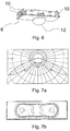
- FIG. 6 An exemplary insert 6 is in FIG. 6 shown.
- the insert 6 has an approximately rectangular base plate, which integrates in the mounted state in the outside of the transparent plate.
- On the back of each two on the opposite narrow sides of the rectangle spring elements 10 are provided, which serve for locking the interchangeable insert 8 on the back (ie the side facing the light source) of the cover 4.
- the locking elements 10 have an approximately U-shaped profile, one leg of the U is connected to the removable insert and the other leg of the U is free to move, so that he after insertion of the removable insert 6 in the opening 8 on the back the cover 4 can engage.
- an elastic locking element may be provided on the cover into which the insert engages.
- the replaceable electrical insert 6 according to FIG. 6 is designed as an emergency lighting system. It has an LED as a light source, which is covered with a refractive optics 12.
- the optic 12 provides an elongated light distribution, as in the FIGS. 7a and 7b is shown.
- Figure 7a the light distribution curve is shown in a horizontal section through the luminaire in polar coordinates.
- the light distribution on the surface to be illuminated is in FIG. 7b shown.
- the light distribution is used, for example, to indicate the direction of an escape route and to illuminate it.
- the emergency light can also serve only as anti-panic lighting, eg with a round or rectangular light distribution, to illuminate the room with an illuminance sufficient for emergencies.
- interchangeable electrical inserts which are not shown in the figures, include luminous intensity sensors, for. B. depending on the ambient brightness to control automatic switching on and off the lamp.
- luminous intensity sensors for. B. depending on the ambient brightness to control automatic switching on and off the lamp.
- motion detectors which are also used to control one or more lights.
- the opening 8 is arranged near the edge of the cover 4.
- the electrical supply cable for the removable electrical insert 6 can be placed directly from the opening 8 to the edge and laid there along the edge on the inside of the cover 4.
- fastening elements along the edge of the cover 4 are provided.
- a tab 14 and an eyelet 16 are shown.
- the termination cable can be passed between the tab 14 and the eyelet 16 and secured to the eyelet 16 by a cable tie.
- the receiving means 14, 16 for the electrical supply also act as a strain relief for the electrical supply, so that when exerting a force on the electrical line, eg when removing the transparent cover 4 from the housing 2, the force is not on the interchangeable electrical insert 6 is transmitted.
- FIGS. 4 and 5 each represent the same section of an edge region of the cover 4.
- an assembly aid 18 is shown on the cover 4.
- the mounting aid 18 is made of a flexible plastic and comprises an elongated shaft which has at its opposite ends in each case a double hook-shaped projection which can be hooked on one side to the cover 4 in an eyelet 20 and on the opposite side of the housing 2 in an eyelet (not shown in the figures) can be hooked.
- the mounting aid 18 serves to be able to attach the cover 4 in the disassembled state to the housing freely suspended, for example, to perform work on the electrical system of the lamp or a removable electrical insert 6.
- the mounting aid may remain in the lamp because it folds along the edge between the housing and the cover 4.
- a hook 22 is shown at the edge of the cover 4, which serves to secure the cover in the housing.
- the hook has a run-up slope towards the housing and a recessed edge.
- the hook 22 cooperates with an elastic latching element (not shown in the figures) on the housing, which is deflected by the run-on slope and engages behind the edge.
Landscapes
- Engineering & Computer Science (AREA)
- General Engineering & Computer Science (AREA)
- Non-Portable Lighting Devices Or Systems Thereof (AREA)
Claims (11)
- Lampe, plus particulièrement lampe à vasque, avec un boîtier de lampe (2) qui est conçu pour loger des luminaires,
et un couvercle (4) amovible au moins partiellement transparent pour la fermeture du boîtier de lampe (2),
le couvercle (4) partiellement transparent comprenant une ouverture (8), qui est conçue pour le logement d'inserts électriques (6) interchangeables, plus particulièrement d'un )capteur ou d'un éclairage de secours en lien avec un insert électrique (6) interchangeable, l'insert électrique (6) étant monté dans l'ouverture (8), caractérisé en ce que l'insert électrique (6) interchangeable comprend des moyens d'encliquetage (10) qui sont encliquetés sur au moins deux bords opposés de l'ouverture (8). - Lampe selon la revendication 1, au moins un dispositif (14, 16) étant intégré, pour la fixation d'une ligne électrique, sur un bord du couvercle (4), qui est recouvert par le boîtier de lampe lorsque la lampe est montée.
- Lampe selon la revendication 2, le dispositif (14, 16) constituant une décharge de traction pour la ligne électrique.
- Lampe selon l'une des revendications précédentes, l'ouverture (8) étant rectangulaire, plus particulièrement avec une longueur entre 40 mm et 70 mm et une largeur entre 10 mm et 30 mm.
- Lampe selon l'une des revendications précédentes, le couvercle transparent (4) étant constitué d'une matière plastique.
- Lampe selon l'une des revendications précédentes, une aide au montage (18) flexible étant fixée entre le couvercle transparent (4) et le boîtier (2), qui permet un accrochage du couvercle transparent (4) au boîtier (2) lorsque le couvercle (4) est démonté.
- Lampe selon la revendication 6, l'aide au montage (18) s'étendant le long d'un bord du couvercle (4), recouvert par le boîtier (2), lorsque le couvercle (4) est monté.
- Lampe selon l'une des revendications précédentes, le couvercle transparent (4) comprenant des crochets (22) qui interagissent avec des éléments d'encliquetage flexibles, qui sont prévus sur le boîtier (2), pour la fermeture de la lampe.
- Lampe selon l'une des revendications 1 à 8, l'insert électrique interchangeable comprenant un capteur, plus particulièrement, un capteur de lumière et/ou un capteur de mouvement.
- Lampe selon l'une des revendications 1 à 9, l'insert électrique interchangeable (6) comprenant un éclairage de secours, plus particulièrement avec une ou plusieurs LED en tant que luminaires de l'éclairage de secours.
- Lampe selon la revendication 10, l'éclairage de secours comprenant une optique (12), plus particulièrement une optique réfractrice, qui répartit la lumière du luminaire de l'éclairage de secours dans une direction longitudinale sur une surface éclairée située en face du couvercle transparent (4).
Applications Claiming Priority (1)
| Application Number | Priority Date | Filing Date | Title |
|---|---|---|---|
| DE102012102697A DE102012102697A1 (de) | 2012-03-29 | 2012-03-29 | Leuchte mit Notlichtöffnung |
Publications (2)
| Publication Number | Publication Date |
|---|---|
| EP2644975A1 EP2644975A1 (fr) | 2013-10-02 |
| EP2644975B1 true EP2644975B1 (fr) | 2016-07-20 |
Family
ID=47844073
Family Applications (1)
| Application Number | Title | Priority Date | Filing Date |
|---|---|---|---|
| EP13156616.8A Active EP2644975B1 (fr) | 2012-03-29 | 2013-02-25 | Éclairage avec fenêtre de secours |
Country Status (2)
| Country | Link |
|---|---|
| EP (1) | EP2644975B1 (fr) |
| DE (1) | DE102012102697A1 (fr) |
Families Citing this family (10)
| Publication number | Priority date | Publication date | Assignee | Title |
|---|---|---|---|---|
| DE202013102915U1 (de) * | 2013-07-03 | 2014-10-06 | Zumtobel Lighting Gmbh | Leuchte mit einem Zusatzelement in Form eines Notlichtelements und/oder eines Sende- bzw. Empfangselement zum Senden und/oder Empfangen elektromagnetischer Strahlung |
| DE202014101309U1 (de) * | 2014-03-21 | 2015-08-07 | Zumtobel Lighting Gmbh | Leuchte für Normalbetrieb und Notbetrieb |
| GB2522285B (en) * | 2014-06-17 | 2015-12-16 | Ansell Electrical Products Ltd | Lighting panel assembly |
| DE102014116740A1 (de) * | 2014-11-17 | 2016-05-19 | Emdedesign Gmbh | Leuchte umfassend wenigstens zwei OLED-Leuchtmittel |
| GB2536423A (en) * | 2015-03-12 | 2016-09-21 | Ansell Electronic Products Ltd | Panel assembly |
| EP3619469A4 (fr) * | 2017-05-03 | 2021-04-28 | Hubbell Incorporated | Appareil d'éclairage à montage mural doté d'un boîtier de capteur externe |
| CN211667616U (zh) | 2019-03-29 | 2020-10-13 | 昕诺飞控股有限公司 | 照明器组装套件、照明器和照明器设施 |
| EP3798502B1 (fr) * | 2019-09-30 | 2021-09-08 | Thorn Lighting Limited | Éclairage de panneau et kit comprenant ledit éclairage de panneau |
| DE202023107494U1 (de) * | 2023-12-19 | 2025-03-20 | Zumtobel Lighting Gmbh | Signaleinrichtung bei einer Leuchte und Leuchte |
| EP4610549A1 (fr) * | 2024-03-01 | 2025-09-03 | Thorn Lighting Ltd. | Luminaire et système de construction d'un luminaire |
Citations (3)
| Publication number | Priority date | Publication date | Assignee | Title |
|---|---|---|---|---|
| JP2002373505A (ja) * | 2001-06-13 | 2002-12-26 | Matsushita Electric Works Ltd | ナイトライト |
| CN202040583U (zh) * | 2011-01-12 | 2011-11-16 | 东莞巨扬电器有限公司 | 可无线传输与接收的微波感应led灯管 |
| CN202144953U (zh) * | 2011-06-14 | 2012-02-15 | 东莞巨扬电器有限公司 | 一种具有遮光结构的led灯泡 |
Family Cites Families (7)
| Publication number | Priority date | Publication date | Assignee | Title |
|---|---|---|---|---|
| US5426572A (en) * | 1993-12-01 | 1995-06-20 | International Lighting Manufacturing Company | Light fixtures |
| US6808283B2 (en) * | 2001-05-16 | 2004-10-26 | Frank Wen-Chung Tsao | Sensitive lighting fixture for construction junction box |
| CN101571276B (zh) * | 2008-04-28 | 2012-03-21 | 富准精密工业(深圳)有限公司 | 发光二极管照明装置 |
| US8324817B2 (en) * | 2008-10-24 | 2012-12-04 | Ilumisys, Inc. | Light and light sensor |
| WO2010116200A1 (fr) * | 2009-04-07 | 2010-10-14 | Yipi Pte Ltd | Lampe et tube à del à économie d'énergie |
| CH700878A2 (de) * | 2009-04-21 | 2010-10-29 | Quadesign Partner Ag | Strassenleuchte. |
| CN201420982Y (zh) * | 2009-06-22 | 2010-03-10 | 光碁科技股份有限公司 | 非抛弃可换修的环保多功能模块式led灯具 |
-
2012
- 2012-03-29 DE DE102012102697A patent/DE102012102697A1/de not_active Ceased
-
2013
- 2013-02-25 EP EP13156616.8A patent/EP2644975B1/fr active Active
Patent Citations (3)
| Publication number | Priority date | Publication date | Assignee | Title |
|---|---|---|---|---|
| JP2002373505A (ja) * | 2001-06-13 | 2002-12-26 | Matsushita Electric Works Ltd | ナイトライト |
| CN202040583U (zh) * | 2011-01-12 | 2011-11-16 | 东莞巨扬电器有限公司 | 可无线传输与接收的微波感应led灯管 |
| CN202144953U (zh) * | 2011-06-14 | 2012-02-15 | 东莞巨扬电器有限公司 | 一种具有遮光结构的led灯泡 |
Also Published As
| Publication number | Publication date |
|---|---|
| DE102012102697A1 (de) | 2013-10-02 |
| EP2644975A1 (fr) | 2013-10-02 |
Similar Documents
| Publication | Publication Date | Title |
|---|---|---|
| EP2644975B1 (fr) | Éclairage avec fenêtre de secours | |
| EP2151899B1 (fr) | Système de bande lumineuse | |
| EP1845396B1 (fr) | Eclairage doté d'au moins une couverture transparente | |
| EP3014169B1 (fr) | Luminaire destiné à être utilisé dans un système de rail d'éclairage ainsi que système de rail d'éclairage | |
| EP2948710B1 (fr) | Luminaire a forme allongee | |
| CH709008A1 (de) | Halter für eine Betriebskomponente einer Leuchte. | |
| EP3114400B1 (fr) | Luminaire ou ensemble lumineux comprenant un élément support allongé et un module lumineux fixé de manière libérable | |
| EP2807419B1 (fr) | Rampe d'éclairage munie de modules d'éclairage pour éclairage indirect | |
| DE202012101318U1 (de) | Gehäuse zur Aufnahme eines Betriebsgeräts zum Betreiben einer oder mehrerer Lichtquellen | |
| EP2940379B1 (fr) | Éclairage | |
| CH708279A1 (de) | Leuchte. | |
| DE102011083993A1 (de) | Lichtband | |
| DE102004044175B4 (de) | Leuchte mit Verschlussmitteln zum lösbaren Befestigen einer Abdeckung an einer Gehäusewanne | |
| EP2816543B1 (fr) | Profil de fixation et dispositif d'éclairage | |
| DE102016104426A1 (de) | Modul für modulare Außenleuchte | |
| DE19721340A1 (de) | Leuchte | |
| DE102014214818A1 (de) | Leuchtmittel-Modul und Leuchte mit mehreren Leuchtmittel-Modulen | |
| DE202016103572U1 (de) | Modul für eine Leuchte, insbesondere für eine Lichtbandleuchte | |
| AT525207B1 (de) | Leuchte zur Beleuchtung von Pflanzen | |
| DE202013103419U1 (de) | Leuchte mit Trägerelement und auswechselbarem Leuchtmittel-Modul | |
| DE102011001113B4 (de) | Leuchte | |
| EP2910843B1 (fr) | Lampe | |
| DE202008004759U1 (de) | Deckenbefestigung für eine Hängeleuchte | |
| EP4477942A1 (fr) | Lampe suspendue avec élément de sécurité | |
| EP3059494A1 (fr) | Systeme de moyen d'eclairage |
Legal Events
| Date | Code | Title | Description |
|---|---|---|---|
| PUAI | Public reference made under article 153(3) epc to a published international application that has entered the european phase |
Free format text: ORIGINAL CODE: 0009012 |
|
| AK | Designated contracting states |
Kind code of ref document: A1 Designated state(s): AL AT BE BG CH CY CZ DE DK EE ES FI FR GB GR HR HU IE IS IT LI LT LU LV MC MK MT NL NO PL PT RO RS SE SI SK SM TR |
|
| AX | Request for extension of the european patent |
Extension state: BA ME |
|
| 17P | Request for examination filed |
Effective date: 20140401 |
|
| RBV | Designated contracting states (corrected) |
Designated state(s): AL AT BE BG CH CY CZ DE DK EE ES FI FR GB GR HR HU IE IS IT LI LT LU LV MC MK MT NL NO PL PT RO RS SE SI SK SM TR |
|
| 17Q | First examination report despatched |
Effective date: 20141210 |
|
| RIC1 | Information provided on ipc code assigned before grant |
Ipc: F21S 9/02 20060101ALI20151015BHEP Ipc: F21V 23/00 20150101ALI20151015BHEP Ipc: F21Y 101/02 20060101ALN20151015BHEP Ipc: F21V 5/04 20060101ALI20151015BHEP Ipc: F21V 17/00 20060101ALI20151015BHEP Ipc: F21V 17/16 20060101ALI20151015BHEP Ipc: F21V 23/04 20060101ALI20151015BHEP Ipc: F21V 3/00 20150101AFI20151015BHEP |
|
| GRAP | Despatch of communication of intention to grant a patent |
Free format text: ORIGINAL CODE: EPIDOSNIGR1 |
|
| INTG | Intention to grant announced |
Effective date: 20160303 |
|
| RIC1 | Information provided on ipc code assigned before grant |
Ipc: F21V 17/00 20060101ALI20160224BHEP Ipc: F21V 3/00 20150101AFI20160224BHEP Ipc: F21V 17/16 20060101ALI20160224BHEP Ipc: F21Y 115/10 20160101ALN20160224BHEP Ipc: F21V 5/04 20060101ALI20160224BHEP Ipc: F21S 9/02 20060101ALI20160224BHEP Ipc: F21V 23/00 20150101ALI20160224BHEP Ipc: F21V 23/04 20060101ALI20160224BHEP |
|
| GRAS | Grant fee paid |
Free format text: ORIGINAL CODE: EPIDOSNIGR3 |
|
| GRAA | (expected) grant |
Free format text: ORIGINAL CODE: 0009210 |
|
| AK | Designated contracting states |
Kind code of ref document: B1 Designated state(s): AL AT BE BG CH CY CZ DE DK EE ES FI FR GB GR HR HU IE IS IT LI LT LU LV MC MK MT NL NO PL PT RO RS SE SI SK SM TR |
|
| REG | Reference to a national code |
Ref country code: GB Ref legal event code: FG4D Free format text: NOT ENGLISH |
|
| REG | Reference to a national code |
Ref country code: CH Ref legal event code: EP |
|
| REG | Reference to a national code |
Ref country code: IE Ref legal event code: FG4D Free format text: LANGUAGE OF EP DOCUMENT: GERMAN |
|
| REG | Reference to a national code |
Ref country code: CH Ref legal event code: NV Representative=s name: ISLER AND PEDRAZZINI AG, CH Ref country code: AT Ref legal event code: REF Ref document number: 814413 Country of ref document: AT Kind code of ref document: T Effective date: 20160815 |
|
| REG | Reference to a national code |
Ref country code: DE Ref legal event code: R096 Ref document number: 502013003761 Country of ref document: DE |
|
| REG | Reference to a national code |
Ref country code: LT Ref legal event code: MG4D |
|
| REG | Reference to a national code |
Ref country code: NL Ref legal event code: MP Effective date: 20160720 |
|
| PG25 | Lapsed in a contracting state [announced via postgrant information from national office to epo] |
Ref country code: LT Free format text: LAPSE BECAUSE OF FAILURE TO SUBMIT A TRANSLATION OF THE DESCRIPTION OR TO PAY THE FEE WITHIN THE PRESCRIBED TIME-LIMIT Effective date: 20160720 Ref country code: NO Free format text: LAPSE BECAUSE OF FAILURE TO SUBMIT A TRANSLATION OF THE DESCRIPTION OR TO PAY THE FEE WITHIN THE PRESCRIBED TIME-LIMIT Effective date: 20161020 Ref country code: HR Free format text: LAPSE BECAUSE OF FAILURE TO SUBMIT A TRANSLATION OF THE DESCRIPTION OR TO PAY THE FEE WITHIN THE PRESCRIBED TIME-LIMIT Effective date: 20160720 Ref country code: NL Free format text: LAPSE BECAUSE OF FAILURE TO SUBMIT A TRANSLATION OF THE DESCRIPTION OR TO PAY THE FEE WITHIN THE PRESCRIBED TIME-LIMIT Effective date: 20160720 Ref country code: IS Free format text: LAPSE BECAUSE OF FAILURE TO SUBMIT A TRANSLATION OF THE DESCRIPTION OR TO PAY THE FEE WITHIN THE PRESCRIBED TIME-LIMIT Effective date: 20161120 Ref country code: RS Free format text: LAPSE BECAUSE OF FAILURE TO SUBMIT A TRANSLATION OF THE DESCRIPTION OR TO PAY THE FEE WITHIN THE PRESCRIBED TIME-LIMIT Effective date: 20160720 Ref country code: FI Free format text: LAPSE BECAUSE OF FAILURE TO SUBMIT A TRANSLATION OF THE DESCRIPTION OR TO PAY THE FEE WITHIN THE PRESCRIBED TIME-LIMIT Effective date: 20160720 |
|
| REG | Reference to a national code |
Ref country code: FR Ref legal event code: PLFP Year of fee payment: 5 |
|
| PG25 | Lapsed in a contracting state [announced via postgrant information from national office to epo] |
Ref country code: PL Free format text: LAPSE BECAUSE OF FAILURE TO SUBMIT A TRANSLATION OF THE DESCRIPTION OR TO PAY THE FEE WITHIN THE PRESCRIBED TIME-LIMIT Effective date: 20160720 Ref country code: ES Free format text: LAPSE BECAUSE OF FAILURE TO SUBMIT A TRANSLATION OF THE DESCRIPTION OR TO PAY THE FEE WITHIN THE PRESCRIBED TIME-LIMIT Effective date: 20160720 Ref country code: PT Free format text: LAPSE BECAUSE OF FAILURE TO SUBMIT A TRANSLATION OF THE DESCRIPTION OR TO PAY THE FEE WITHIN THE PRESCRIBED TIME-LIMIT Effective date: 20161121 Ref country code: SE Free format text: LAPSE BECAUSE OF FAILURE TO SUBMIT A TRANSLATION OF THE DESCRIPTION OR TO PAY THE FEE WITHIN THE PRESCRIBED TIME-LIMIT Effective date: 20160720 Ref country code: LV Free format text: LAPSE BECAUSE OF FAILURE TO SUBMIT A TRANSLATION OF THE DESCRIPTION OR TO PAY THE FEE WITHIN THE PRESCRIBED TIME-LIMIT Effective date: 20160720 Ref country code: GR Free format text: LAPSE BECAUSE OF FAILURE TO SUBMIT A TRANSLATION OF THE DESCRIPTION OR TO PAY THE FEE WITHIN THE PRESCRIBED TIME-LIMIT Effective date: 20161021 |
|
| REG | Reference to a national code |
Ref country code: DE Ref legal event code: R097 Ref document number: 502013003761 Country of ref document: DE |
|
| PG25 | Lapsed in a contracting state [announced via postgrant information from national office to epo] |
Ref country code: EE Free format text: LAPSE BECAUSE OF FAILURE TO SUBMIT A TRANSLATION OF THE DESCRIPTION OR TO PAY THE FEE WITHIN THE PRESCRIBED TIME-LIMIT Effective date: 20160720 Ref country code: RO Free format text: LAPSE BECAUSE OF FAILURE TO SUBMIT A TRANSLATION OF THE DESCRIPTION OR TO PAY THE FEE WITHIN THE PRESCRIBED TIME-LIMIT Effective date: 20160720 |
|
| PLBE | No opposition filed within time limit |
Free format text: ORIGINAL CODE: 0009261 |
|
| STAA | Information on the status of an ep patent application or granted ep patent |
Free format text: STATUS: NO OPPOSITION FILED WITHIN TIME LIMIT |
|
| PG25 | Lapsed in a contracting state [announced via postgrant information from national office to epo] |
Ref country code: BE Free format text: LAPSE BECAUSE OF NON-PAYMENT OF DUE FEES Effective date: 20170228 Ref country code: DK Free format text: LAPSE BECAUSE OF FAILURE TO SUBMIT A TRANSLATION OF THE DESCRIPTION OR TO PAY THE FEE WITHIN THE PRESCRIBED TIME-LIMIT Effective date: 20160720 Ref country code: SK Free format text: LAPSE BECAUSE OF FAILURE TO SUBMIT A TRANSLATION OF THE DESCRIPTION OR TO PAY THE FEE WITHIN THE PRESCRIBED TIME-LIMIT Effective date: 20160720 Ref country code: SM Free format text: LAPSE BECAUSE OF FAILURE TO SUBMIT A TRANSLATION OF THE DESCRIPTION OR TO PAY THE FEE WITHIN THE PRESCRIBED TIME-LIMIT Effective date: 20160720 Ref country code: CZ Free format text: LAPSE BECAUSE OF FAILURE TO SUBMIT A TRANSLATION OF THE DESCRIPTION OR TO PAY THE FEE WITHIN THE PRESCRIBED TIME-LIMIT Effective date: 20160720 Ref country code: BG Free format text: LAPSE BECAUSE OF FAILURE TO SUBMIT A TRANSLATION OF THE DESCRIPTION OR TO PAY THE FEE WITHIN THE PRESCRIBED TIME-LIMIT Effective date: 20161020 |
|
| 26N | No opposition filed |
Effective date: 20170421 |
|
| PG25 | Lapsed in a contracting state [announced via postgrant information from national office to epo] |
Ref country code: SI Free format text: LAPSE BECAUSE OF FAILURE TO SUBMIT A TRANSLATION OF THE DESCRIPTION OR TO PAY THE FEE WITHIN THE PRESCRIBED TIME-LIMIT Effective date: 20160720 |
|
| PG25 | Lapsed in a contracting state [announced via postgrant information from national office to epo] |
Ref country code: MC Free format text: LAPSE BECAUSE OF FAILURE TO SUBMIT A TRANSLATION OF THE DESCRIPTION OR TO PAY THE FEE WITHIN THE PRESCRIBED TIME-LIMIT Effective date: 20160720 |
|
| REG | Reference to a national code |
Ref country code: IE Ref legal event code: MM4A |
|
| PG25 | Lapsed in a contracting state [announced via postgrant information from national office to epo] |
Ref country code: LU Free format text: LAPSE BECAUSE OF NON-PAYMENT OF DUE FEES Effective date: 20170225 |
|
| REG | Reference to a national code |
Ref country code: BE Ref legal event code: MM Effective date: 20170228 |
|
| REG | Reference to a national code |
Ref country code: FR Ref legal event code: PLFP Year of fee payment: 6 |
|
| PG25 | Lapsed in a contracting state [announced via postgrant information from national office to epo] |
Ref country code: IE Free format text: LAPSE BECAUSE OF NON-PAYMENT OF DUE FEES Effective date: 20170225 |
|
| PGFP | Annual fee paid to national office [announced via postgrant information from national office to epo] |
Ref country code: GB Payment date: 20180216 Year of fee payment: 6 Ref country code: CH Payment date: 20180216 Year of fee payment: 6 |
|
| PGFP | Annual fee paid to national office [announced via postgrant information from national office to epo] |
Ref country code: IT Payment date: 20180227 Year of fee payment: 6 |
|
| PG25 | Lapsed in a contracting state [announced via postgrant information from national office to epo] |
Ref country code: MT Free format text: LAPSE BECAUSE OF FAILURE TO SUBMIT A TRANSLATION OF THE DESCRIPTION OR TO PAY THE FEE WITHIN THE PRESCRIBED TIME-LIMIT Effective date: 20160720 |
|
| PG25 | Lapsed in a contracting state [announced via postgrant information from national office to epo] |
Ref country code: AL Free format text: LAPSE BECAUSE OF FAILURE TO SUBMIT A TRANSLATION OF THE DESCRIPTION OR TO PAY THE FEE WITHIN THE PRESCRIBED TIME-LIMIT Effective date: 20160720 |
|
| PG25 | Lapsed in a contracting state [announced via postgrant information from national office to epo] |
Ref country code: HU Free format text: LAPSE BECAUSE OF FAILURE TO SUBMIT A TRANSLATION OF THE DESCRIPTION OR TO PAY THE FEE WITHIN THE PRESCRIBED TIME-LIMIT; INVALID AB INITIO Effective date: 20130225 |
|
| REG | Reference to a national code |
Ref country code: CH Ref legal event code: PL |
|
| GBPC | Gb: european patent ceased through non-payment of renewal fee |
Effective date: 20190225 |
|
| PG25 | Lapsed in a contracting state [announced via postgrant information from national office to epo] |
Ref country code: CY Free format text: LAPSE BECAUSE OF NON-PAYMENT OF DUE FEES Effective date: 20160720 |
|
| PG25 | Lapsed in a contracting state [announced via postgrant information from national office to epo] |
Ref country code: MK Free format text: LAPSE BECAUSE OF FAILURE TO SUBMIT A TRANSLATION OF THE DESCRIPTION OR TO PAY THE FEE WITHIN THE PRESCRIBED TIME-LIMIT Effective date: 20160720 |
|
| PG25 | Lapsed in a contracting state [announced via postgrant information from national office to epo] |
Ref country code: CH Free format text: LAPSE BECAUSE OF NON-PAYMENT OF DUE FEES Effective date: 20190228 Ref country code: LI Free format text: LAPSE BECAUSE OF NON-PAYMENT OF DUE FEES Effective date: 20190228 |
|
| PG25 | Lapsed in a contracting state [announced via postgrant information from national office to epo] |
Ref country code: GB Free format text: LAPSE BECAUSE OF NON-PAYMENT OF DUE FEES Effective date: 20190225 |
|
| PG25 | Lapsed in a contracting state [announced via postgrant information from national office to epo] |
Ref country code: IT Free format text: LAPSE BECAUSE OF NON-PAYMENT OF DUE FEES Effective date: 20190225 |
|
| REG | Reference to a national code |
Ref country code: DE Ref legal event code: R082 Ref document number: 502013003761 Country of ref document: DE Representative=s name: BOEHMERT & BOEHMERT ANWALTSPARTNERSCHAFT MBB -, DE Ref country code: DE Ref legal event code: R081 Ref document number: 502013003761 Country of ref document: DE Owner name: SITECO GMBH, DE Free format text: FORMER OWNER: SITECO BELEUCHTUNGSTECHNIK GMBH, 83301 TRAUNREUT, DE |
|
| PG25 | Lapsed in a contracting state [announced via postgrant information from national office to epo] |
Ref country code: TR Free format text: LAPSE BECAUSE OF FAILURE TO SUBMIT A TRANSLATION OF THE DESCRIPTION OR TO PAY THE FEE WITHIN THE PRESCRIBED TIME-LIMIT Effective date: 20160720 |
|
| REG | Reference to a national code |
Ref country code: AT Ref legal event code: PC Ref document number: 814413 Country of ref document: AT Kind code of ref document: T Owner name: SITECO GMBH, DE Effective date: 20201028 |
|
| PGFP | Annual fee paid to national office [announced via postgrant information from national office to epo] |
Ref country code: FR Payment date: 20230217 Year of fee payment: 11 |
|
| PG25 | Lapsed in a contracting state [announced via postgrant information from national office to epo] |
Ref country code: FR Free format text: LAPSE BECAUSE OF NON-PAYMENT OF DUE FEES Effective date: 20240229 |
|
| PG25 | Lapsed in a contracting state [announced via postgrant information from national office to epo] |
Ref country code: FR Free format text: LAPSE BECAUSE OF NON-PAYMENT OF DUE FEES Effective date: 20240229 |
|
| PGFP | Annual fee paid to national office [announced via postgrant information from national office to epo] |
Ref country code: DE Payment date: 20260217 Year of fee payment: 14 |
|
| PGFP | Annual fee paid to national office [announced via postgrant information from national office to epo] |
Ref country code: AT Payment date: 20260216 Year of fee payment: 14 |