EP4477942A1 - Lampe suspendue avec élément de sécurité - Google Patents
Lampe suspendue avec élément de sécurité Download PDFInfo
- Publication number
- EP4477942A1 EP4477942A1 EP24180353.5A EP24180353A EP4477942A1 EP 4477942 A1 EP4477942 A1 EP 4477942A1 EP 24180353 A EP24180353 A EP 24180353A EP 4477942 A1 EP4477942 A1 EP 4477942A1
- Authority
- EP
- European Patent Office
- Prior art keywords
- pendulum
- pendulum body
- pendant
- securing element
- securing
- Prior art date
- Legal status (The legal status is an assumption and is not a legal conclusion. Google has not performed a legal analysis and makes no representation as to the accuracy of the status listed.)
- Granted
Links
Images

Classifications
-
- F—MECHANICAL ENGINEERING; LIGHTING; HEATING; WEAPONS; BLASTING
- F21—LIGHTING
- F21V—FUNCTIONAL FEATURES OR DETAILS OF LIGHTING DEVICES OR SYSTEMS THEREOF; STRUCTURAL COMBINATIONS OF LIGHTING DEVICES WITH OTHER ARTICLES, NOT OTHERWISE PROVIDED FOR
- F21V21/00—Supporting, suspending, or attaching arrangements for lighting devices; Hand grips
- F21V21/10—Pendants, arms, or standards; Fixing lighting devices to pendants, arms, or standards
- F21V21/112—Fixing lighting devices to pendants
-
- F—MECHANICAL ENGINEERING; LIGHTING; HEATING; WEAPONS; BLASTING
- F21—LIGHTING
- F21S—NON-PORTABLE LIGHTING DEVICES; SYSTEMS THEREOF; VEHICLE LIGHTING DEVICES SPECIALLY ADAPTED FOR VEHICLE EXTERIORS
- F21S8/00—Lighting devices intended for fixed installation
- F21S8/04—Lighting devices intended for fixed installation intended only for mounting on a ceiling or the like overhead structures
- F21S8/06—Lighting devices intended for fixed installation intended only for mounting on a ceiling or the like overhead structures by suspension
- F21S8/061—Lighting devices intended for fixed installation intended only for mounting on a ceiling or the like overhead structures by suspension with a non-rigid pendant, i.e. a cable, wire or chain
Definitions
- the present invention relates to a pendant luminaire with a pendulum body and a pendant structure connectable to the pendulum body.
- the pendulum body is suspended via a rope suspension or another type of pendulum structure using a pendulum element (e.g. rope).
- the rope suspension can be connected to the pendulum body so that the pendulum body can be suspended in a pendulum-like manner.
- the assembly should be simplified.
- the present invention relates to a pendant lamp with a lamp body having a connecting structure (hereinafter also referred to as a pendulum body), a pendulum structure with at least one pendulum element that can be connected to the pendulum body via its connecting structure in order to support the pendulum body in a suspended manner, and a securing element for each pendulum element for securing the pendulum element in the connecting structure.
- the connecting structure has an access opening for inserting the pendulum element and an access slot adjacent to the access opening for pulling in the pendulum element.
- the securing element can be fastened to the pendulum body in such a way that the securing element blocks the pendulum element in the connecting structure towards the access opening and thus secures it in the connecting structure.
- the securing element preferably has a plate shape or extends essentially in one plane.
- a pendant luminaire whose pendulum-suspended base body (i.e. the pendulum body) is suspended via a preferably elongated suspension (as the pendulum structure; e.g. a rope suspension) can be hung up.
- the suspension can be connected to the base body - preferably detachably.
- the base body has a connecting device (i.e. the connecting structure).
- the connecting device has an access opening and an (access) slot leading away from it, which are preferably designed to correspond to the suspension.
- the connecting device serves to connect to the suspension, wherein the suspension can be inserted or pulled into it, in particular to establish the connection.
- An aid i.e. the securing element
- the aid can lock the connecting device when connected to the suspension.
- the aid can be a sheet or a plate or a section thereof or can have this/these.
- the securing element which is at least partially plate-shaped and/or extends essentially in one plane, serves to particularly easily secure the pendulum element connected to the pendulum body.
- the securing element can be easily attached to the pendulum body, for example, which is already suspended in a pendulum manner, in order to prevent the pendulum element from coming loose.
- the securing element can be made more difficult or prevented that the lamp body is intentionally and/or accidentally unhooked. This not only improves theft protection, but also safety, e.g. against falling down.
- this makes it easier to release the pendulum element from the pendulum body, because previously known solutions for this usually require dismantling the pendulum body or the pendant lamp or other structural parts thereof in order to remove the pendulum element.
- the pendant structure or pendant element is secured in a way that is visually inconspicuous but effective due to the flat design of the securing element.
- the pendant light can be fully assembled before it is finally hung with the pendant structure and effectively secured using the compact securing element. This also simplifies the installation of the pendant light.
- connection structure is to be understood in particular as a component of the pendulum body.
- the connection structure can be incorporated into a base body of the pendulum body or into the pendulum body itself.
- the connection structure can be a part attached to a base body of the pendulum body or to the pendulum body itself. or a fixed device.
- the connection structure can have and/or form a form-fitting geometry.
- the form-fitting geometry can be designed to correspond to the pendulum element.
- the connection structure can be introduced into the pendulum body by punching or laser cutting, for example.
- the pendulum body is basically a main body - e.g. the lamp body or a lamp housing - of the pendant lamp.
- the pendulum body can accommodate lamps, electronics, wiring and/or control components for lighting or can be used to attach them.
- the pendulum body can be made of plastic and/or metal or can be made from it.
- the pendulum body can be coated and/or painted, preferably electrically non-conductive.
- a pendulum structure is to be understood as a connecting structure, in particular for realizing a pendulum suspension of the pendulum body.
- This has one or more pendulum elements (e.g. cables).
- the pendulum element is then basically to be understood as a preferably elongated and/or flexible or bendable connecting element in order to realize the pendulum suspension of the pendulum body.
- the pendulum structure or its pendulum element can also be designed to be rigid at least in sections or essentially completely, in particular have one or more rods or be formed from them.
- the pendulum element preferably has two opposite or opposite ends.
- the pendulum element preferably has at least one end corresponding to the pendulum body or several of them.
- the pendulum structure can - designed as a cable suspension or having this - preferably have a cable, preferably a wire cable, or several of them as pendulum element(s).
- the securing element is preferably understood to be a component.
- the securing element can be formed in one piece and/or monolithically.
- the securing element can be essentially plate-shaped in sections, predominantly or exclusively.
- the securing element can have a projection and/or a recess.
- the securing element can be notched.
- the securing element can preferably engage in the connecting structure and/or cover it.
- the securing element can be provided for blocking several connecting structures.
- Blocking is understood in particular to mean that something is blocked or locked, for example an access, a path, an opening, a mechanism, a mechanism. Blocking in particular prevents the pendulum element from being pulled in or inserted or pulled out of the connecting structure; this in particular towards the access opening through which the pendulum element can be or was inserted into the connecting structure. Blocking preferably restricts movement of the pendulum element in at least one direction, preferably two directions directed transversely to one another, preferably along the access path.
- the plate shape is understood in particular to mean a shape that extends predominantly along a flat surface.
- the plate shape can have a thickness that is at least one order of magnitude smaller than a width and/or a length of the plate shape.
- a plate shape is elongated in two directions oriented orthogonally to one another and is not elongated in the vertical direction oriented orthogonally to these two directions.
- a plate shape is at least one order of magnitude larger in one or both of two directions oriented orthogonally to one another than in the vertical direction.
- the plate shape can make up a section of the securing element.
- the securing element can be formed at least substantially from the plate shape.
- the securing element is flat overall; thus, it has the plate shape or extends substantially in one plane.
- the securing element can preferably have structural areas that protrude or recede from the plane or the plate extension at certain points, although a significant majority of the securing element lies in the plane or defines the plate shape.
- the connecting structure is advantageously designed in such a way that the pendulum element introduced via the access opening can be moved via the access slot into a support position in which the pendulum element can support the pendulum body in a suspended manner.
- the pendulum element can be inserted into the connecting structure, moved laterally within the connecting structure and then only partially moved out of the connecting structure again in order to reach the support position.
- the securing element advantageously serves to additionally secure the existence of the support position.
- the connecting structure can be designed in this way - e.g. inclined - it can be provided that the pendulum element is retracted into the connecting structure - and thus away from the access opening - due to the weight of the pendulum body.
- the securing element is detachably attached to the pendulum body.
- the securing element can be clipped and/or screwed to the pendulum body.
- the securing element can be designed for preferably detachable attachment to the pendulum body.
- the securing element and pendulum body can be connected to one another or attached to one another.
- the securing element and/or the pendulum body can have a catch for clipping.
- the securing element can be screwed to the pendulum body, or vice versa.
- Detachable attachment enables non-destructive release in particular. This enables a particularly user-friendly and time-saving attachment option. In particular, the attachment saves material if it is detachable.
- the pendulum body has a fastening option or fastening structure for the securing element.
- This can be, for example, a (e.g. a single) through-opening into which a self-tapping screw can be screwed to fasten the securing element to the pendulum body.
- the fastening structure can also already have a thread; e.g. an internal thread or an external thread. Several threads can be provided. An internal thread is preferred.
- the securing element can have a passage for a (e.g. a single) screw to secure it to the pendulum body.
- the passage is preferably a bore and/or a hole or perforation. Several passages can be provided. This creates a secure and, in particular, non-destructively detachable fastening option.
- the fastening option also shortens the assembly time and thus reduces costs.
- the securing element is designed to rest flatly on the pendulum body.
- the securing element can be designed to correspond to a surface on the pendulum body in order to be able to rest flatly and/or in surface contact with the pendulum body at least in some areas.
- the securing element can rest flat on the pendulum body. This can simplify assembly.
- a force-fit connection can be provided via the flat contact, which improves safety.
- the securing element attached or to be attached to the pendulum body is intended to block the pendulum element, preferably towards the access opening, by at least partially covering the connection structure, preferably the access opening and/or the access slot.
- the blocking is caused by covering or concealing the connection structure.
- the securing element engages in the connection structure and/or blocks it by engaging it.
- the securing element covers the connection structure and/or blocks it by covering it, preferably in surface contact, e.g. with an area surrounding the connection structure on the pendulum body.
- a force and/or form fit is caused, which can prevent the pendulum element from coming loose from the connection structure and thus increase safety.
- the pendulum body has a structural section which, when the securing element is fastened to the pendulum body, is in a positive connection with a counter-structural section of the securing element, preferably at least with respect to the plane or with respect to an extension direction of the securing element.
- a counter-structural section of the securing element preferably at least with respect to the plane or with respect to an extension direction of the securing element.
- an anti-twisting device for the securing element can be provided.
- the structural section can form a positive connection with the securing element.
- the structural section can be a projection and/or a bead or have these.
- the structural section can be incorporated into the pendulum body, for example punched and/or embossed.
- the structural section can be provided or designed to fix a feed cable coming from the pendulum structure or the pendulum element.
- the feed cable can be provided to supply power to the pendulum light.
- the securing element can alternatively or additionally have a structural section for fixing a feed cable coming from the pendulum structure or the pendulum element.
- This structural section can preferably have a projection and/or a bead.
- the structural section can be incorporated into the securing element, for example, punched and/or embossed.
- the Structural element can be incorporated into the manufacturing process of the securing element - e.g. in the same punching and bending process or the same laser cutting process.
- the security element has a sheet metal part and/or a stamped and bent part and/or a formed part, preferably being formed from it.
- the security element is preferably made of metal.
- the structural section, the passage or other areas or functions of the security element can be realized cost-effectively as a stamped and bent part.
- a contour and/or the shape, in particular plate shape, of the security element can also be provided particularly easily.
- the security element can preferably be coated and/or painted in an electrically non-conductive manner.
- the security element can also advantageously be galvanized or provided with an anti-corrosive coating (e.g. coated).
- the security element has or consists of a plastic part and/or a (plastic) injection-molded part.
- the security element can be made of plastic.
- the security element can be designed to be electrically non-conductive at least on the surface or at least essentially or completely. The security element can thus be manufactured easily and inexpensively in mass production, saving weight and inhibiting corrosion.
- the access slot runs - at least essentially, preferably completely - in a straight line.
- the access slot can also run at least partially in a non-straight line, such as curved and/or jagged or kinked.
- the access slot can have opposing boundaries for guiding, in particular for inserting, guiding and/or leading out, the pendulum element.
- the boundaries have an at least essentially constant distance from one another.
- the access slot has an essentially constant width along its extension.
- the boundaries can run at least essentially parallel.
- the access slot is wider than at least a section of the pendulum element, but narrower than an end of the pendulum element (e.g. distal) that is suspended in the connection structure.
- the access slot enables simple assembly and provides an advantageous option for blocking.
- connection structure has a holding opening adjacent to the access slot.
- the holding opening is preferably provided for pulling the pendulum element out of the access slot and more preferably for storing the pendulum element in the connection structure.
- the holding opening typically borders directly on the access slot or the access slot merges into the holding opening.
- the holding opening can be essentially round.
- the holding opening can preferably be larger in the radial direction than the pendulum element in the radial direction, but smaller than an end of the pendulum element directed towards the connection structure. The holding opening serves for intuitive assembly of the pendulum element and for securing.
- the access opening and/or the holding opening and/or the projection segment can be round, preferably circular, or polygonal, preferably rectangular or square.
- the holding opening and/or the access opening can be designed to correspond to the projection segment or have the same shape. The advantageous purpose is therefore that the pendulum element can be easily inserted into the connection structure through the access opening or can be held or stored in a defined manner by the holding opening and can preferably be blocked.
- the fact that the holding opening is designed to correspond to the projection segment can advantageously ensure that the pendulum element or its projection segment fits into the access opening in only one orientation, for example vertically, which makes the installation of the pendulum element into the connection structure easier and safer.
- the connecting structure is formed from an opening in the pendulum body.
- the connecting structure can be incorporated into the pendulum body as an opening, for example punched or laser-cut.
- the opening is preferably understood to be a material recess and/or a passage. This enables cost-effective production.
- the structural arrangement is provided in particular for a single pendulum element (e.g. a cable), wherein the pendulum element or cable is preferably designed to correspond to all connecting structures of this structural arrangement.
- the suspension structure can have a single suspension element or rope or can have several suspension elements or ropes. This means that, depending on the requirements, an effective and safe suspension can be provided.
- the access slots of the structural arrangement can run substantially adjacent to one another and/or substantially parallel to one another.
- the structure of the structural arrangement can be simplified and the assembly of the suspension element can be simplified.
- Each of the pendant elements can have an end section for each of the connecting structures of the associated structural arrangement and/or can be inverted Y-shaped or fork-shaped on the side of the connecting structures. This provides a particularly compact yet securely attachable pendant light.
- the pendant element has a coupling element.
- the coupling element is preferably provided to connect the pendant element to itself and/or a pendant element or cable of the pendant structure to itself.
- the end sections facing the pendulum body and a support section of the pendant element facing away from the pendulum body are preferably connected via the coupling element.
- the coupling element can have coupling parts that correspond to one another. The coupling element improves the ability to mount the pendant light.
- At least one connecting structure and/or at least one structural arrangement is provided on opposite sides of the pendulum body - preferably with respect to a longitudinal extension of the (preferably elongated) pendulum body - to each of which one of the pendulum elements is assigned.
- the pendulum body can be suspended at two ends or sides, in particular in a pendulum-like manner.
- the opposite sides are preferably more than 10 cm or more than 20 cm, preferably more than 50 cm, apart from each other. This can increase stability.
- the suspension structure or the cable suspension has a second cable, which is preferably at least substantially identical in construction to the first Rope is formed.
- the ropes can be the same length, have the same weight and/or have the same end sections.
- a single rope can also be provided for two or more connecting structures or structural arrangements, e.g. which is deflected away from the pendulum body or on the ceiling side, and preferably has end sections. This makes it easier to align the pendant light. What has been said for the ropes also applies to other types of pendant elements; e.g. rods.
- the pendant element or each of the end sections can have a coupling section which has a projection segment and a recess segment, and optionally also comprises a pendulum segment (such as a rope segment).
- the end section is intended in particular for insertion or introduction into the access opening.
- the pendulum element or the rope preferably ends on the side of the pendulum body with the projection segment.
- the projection segment and the recess segment can be formed in one piece with one another and can preferably be attached to the pendulum segment.
- the recess segment can be crimped on the pendulum segment.
- the projection segment is designed to be inserted into the access opening; for example, it is smaller than the access opening.
- the projection segment is smaller in diameter or radially and/or transversely to the direction of extension of the pendulum element than the access opening.
- the projection segment for striking or supporting in the area of the holding opening is larger than the holding opening.
- the projection segment is preferably larger than the access slot.
- the projection segment is preferably larger in diameter or radially and/or transversely to the direction of extension of the pendant element than the holding opening and/or the access slot.
- the pushed-through projection segment can thus strike against the edge of the connecting structure, particularly preferably from the inside, on the connection structure, particularly preferably in the area of the holding opening or the access slot, in order to suspend the pendant lamp in a pendulum-supporting manner.
- the recess segment is smaller than the access opening and/or the holding opening.
- the recess segment is preferably smaller than the access opening or the holding opening.
- the recess segment is preferably smaller in diameter or radially and/or transversely to the The direction of extension of the pendulum element is smaller than the access opening or the holding opening. This makes it easier to push the pendulum element through. The pendulum element can thus be stabilized via the recess segment.
- the recess segment is smaller or larger than the access slot. It is preferred if the recess segment is larger than the access slot. This means that the recess segment cannot be pushed or pulled into the access slot in order to provide a positive locking mechanism. In other words, the recess segment can be wider than the access slot transversely to the direction of extension of the pendulum element in order to prevent it from being pulled into the access slot.
- the access opening preferably has a diameter of 5 mm to 10 mm, particularly preferably 8.5 mm.
- the opening preferably has a diameter of 2 mm to 6 mm, particularly preferably 4.5 mm.
- a light source accommodated in the pendulum body can be provided for emitting light from the pendulum lamp.
- the light source can be attached directly or indirectly to the pendulum body. It is preferred if the light source is aligned and/or designed to emit light in a direction away from the connecting structure and/or the structural arrangement and/or the pendulum structure or the pendulum element.
- the pendulum lamp can at least partially, preferably predominantly or exclusively, illuminate in a direction away from the pendulum element.
- the light source has, for example, at least one LED or one LED module.
- the pendant light can preferably have a pendulum body cover for covering a supply electronics.
- the supply electronics can be fixed to the pendulum body, for example on the back of the pendulum body and/or next to the connecting structure or structural arrangement, in particular between connecting structures or structural arrangements.
- the supply electronics can be supplied with electrical energy by the feed cable.
- the pendulum body cover can be designed as a cover.
- the pendulum body cover can have a cable feedthrough for a cable, for example the feed cable.
- the pendulum body cover can be fixed to the pendulum body next to the A safety element can be attached.
- the pendulum body cover is preferably designed to be electrically insulating.
- the pendulum body cover is a sheet metal part, preferably made of metal and/or plastic.
- the pendulum body cover can be coated and/or painted for mechanical and/or electrical protection, preferably electrically non-conductive. Since the safety element is provided independently of the pendulum body cover, the pendulum body cover can already be fully assembled before the pendulum body is then suspended using the pendulum element and then secured using the safety element.
- the pendulum body has a sheet metal part or consists of it.
- the pendulum body can be a formed part and/or an injection-molded part.
- the pendulum body is preferably designed to be electrically insulating.
- the pendulum body is a sheet metal part, preferably made of metal and/or plastic.
- the pendulum body can be coated and/or painted for mechanical and/or electrical protection, preferably electrically non-conductive.
- a support element can be provided for connection to a ceiling and to the pendant structure or the pendant element.
- the support element can be attached directly or indirectly to a ceiling and/or a ceiling element.
- the support element can be arranged above the pendulum body.
- the support element can be a component of the pendant light.
- a light distribution body can be provided that extends over a large area, is preferably transparent, preferably surrounds the pendulum body or extends laterally away from the pendulum body (10) on one side, on both sides or on the circumference.
- the light distribution body can be or have a light guide plate, a light optic or a light cover.
- the light distribution body can be made of glass and/or plastic.
- the light distribution body can have a preferably central recess for the pendulum body.
- the lighting means can be inserted into this recess, for example, and thus shine laterally into the light distribution body, which is designed, for example, as a light guide plate.
- the light guide plate can then have coupling-out structures in order to emit the light propagating in the light guide plate in a defined coupling-out direction (for example downwards for primary lighting or upwards or to the side for secondary lighting) for lighting.
- the pendulum body, the light distribution body and/or the light source is/are elongated and/or elongated.
- One of the pendulum elements can be attached to opposite ends of the pendulum body with one or more pendulum sections or ropes in order to create a robust attachment.
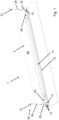
- the figures show an embodiment of a pendant lamp 1 according to the invention.
- the pendant light 1 is shown with a view of its fastening side - here the rear side - 2.
- the pendant light 1 has a pendulum body 10, preferably a pendulum body cover 11, a pendulum structure 30 with at least one pendulum element 31, one - here two - securing elements 40 for each pendulum element 31 and here preferably a plate-shaped light distribution body 50.
- a light source is preferably attached to the pendulum body 10, which can illuminate in a direction facing away from the rear side 2.
- the light source is preferably operated by means of electronics or supply electronics arranged on the rear side, which is preferably covered by the pendulum body cover 11 here.
- the light distribution body 50 preferably extends flatly, is transparent and encloses the pendulum body 10.
- the light distribution body 50 preferably extends from the pendulum body 10 on one side, on both sides or - as in Fig. 1 shown - circumferentially to the side.
- the pendulum body 10, the light distribution body 50 and the illuminant can be elongated or elongated, as in Fig. 1 shown as an example.
- the light distribution body 50 has a recess for the pendulum body 10 and preferably also for receiving the lighting means.
- the pendulum body 10 has - here preferably a total of four - connecting structures 12.
- Two connecting structures 12 each form a structural arrangement 13.
- the suspension structure 30 may be or have a cable suspension.
- the pendulum structure 30 can be connected or is to be connected to the pendulum body 10.
- the pendulum structure or the cable suspension 30 is connected to the pendulum body 10 as intended.
- the pendulum structure 30 has at least one and present two pendulum sections 31, which can be connected or are connected to the pendulum body 10 via the respective connecting structures 12 in order to support the pendulum body 10 in a pendulum-like manner, as shown in Fig. 1 is shown.
- the pendulum section 31 has one cable - in this case a total of two cables 31.
- a support section 34 and an end section 35 are provided on each of the pendulum elements or cables 31.
- the end section 35 faces or is to face the pendulum body 10.
- Each of the end sections 35 serves to connect to one of the two structural arrangements 13 or the connecting structure 12; here the pair of connecting structures 12 per structural arrangement 13.
- the connecting structure 12 has an access opening 14 for inserting the pendulum portion 31 and an access slot 16 adjacent to the access opening 14 for pulling in the respective pendulum section 31, preferably starting from the access opening 14.
- the two securing elements 40 are preferably detachably connected to the pendulum body 10 or fastened thereto.
- the securing elements 40 are each fastened or can be fastened to the pendulum body 10 in such a way that the securing element 40 blocks the respective pendulum section 31 in the connecting structure 12 towards the access opening 14 and thus secures it in the connecting structure 12.
- One of the securing elements 40 is screwed to the pendulum body 10 (right in Fig. 1 ).
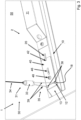
- the other safety element 40 is shown in an exploded view at a distance from the pendulum body 10 (left in Fig. 1 and in Fig. 2 ).
- the securing elements 40 each have a plate shape or extend essentially in a plane, as is particularly the case with Fig. 2 and 3 can be seen.
- the securing element 40 can be releasably fastened to the pendulum body 10, for example by screwing.
- the pendulum body 10 preferably has a fastening structure 22 for each of the securing elements 40; here in the form of a through-opening.
- a screw 48 used to fasten the securing element 40 can be provided as a self-tapping screw and cut a thread into the through-opening 22 of the pendulum body 10.
- the fastening structure 22 has a thread, more precisely an internal thread and/or threaded hole.
- the securing element 40 here preferably has a passage 44 for the screw 48 for securing to the pendulum body 10.
- exactly one fastening structure 22 is provided for a securing element 40.
- the securing element 40 can have a catch and/or a projection that engages or passes through the pendulum body 10.
- the pendulum body can also have a catch and/or a projection that engages or passes through the securing element 40.
- the securing element 40 is designed to lie flat against the pendulum body 10 or can lie flat against the pendulum body 10, cf. Fig. 1-3 .
- the securing element 40 is preferably provided for blocking the structural arrangement 13 or one or all of the connecting structures 12 - thus for blocking the respective pendulum section 31 towards the access opening 14 - by at least partially covering the respective connecting structure(s) 12. More precisely, the securing element 40 can cover the access opening 14 at least partially or completely and/or the access slot 16 at least partially or completely, preferably more than 10%, 50% or 75% of its extension.
- the pendulum body 10 has a structural section 20 which, when the securing element 40 is attached to the pendulum body 10, is in a form-fitting connection with a counter-structural section 42 of the securing element 40; this is preferably at least with respect to the plane or the plate-shaped extension.
- the structural sections 20, 42 can thus be provided as a rotation lock for the securing element 40 and for engagement in the securing element 40, as shown in Fig. 3 can be seen.
- the counter-structure section 42 here has, for example, a recess 42 into which the structure section 20 can engage, e.g. when the securing element 40 is fastened and/or rests against the pendulum body 10 (e.g. flat).
- the recess 42 is preferably a notch, for example - as in the present case - on the edge of the securing element 40.
- the structural portion 20 is preferably spaced from the fastening structure 22 and more preferably along the securing element 40, as can be seen from Fig. 2 and 3 is evident.
- the structural section 20 can, for example, be or have a projection or a bead, preferably for fixing a feed cable coming from the pendulum structure 30 or from the or one of the pendulum sections 31.
- the feed cable can be attached to the structural section 20 via a fastening means, such as a cable tie and/or a fastening wire.
- the securing element 40 preferably has a structural section 46, which can be designed as a projection or a bead, and which, comparable to the structural section 20, can also be provided for fixing the feed cable.
- the structural section 20 of the pendulum body 10 is used as an anti-twist device for the securing element 40 and the structural section 46 of the securing element 40 is used as a fastening for the feed cable.
- the positive connection of the structural section 20 with the counter-structural section 42 can preferably be designed in such a way that the structural section 20 continues to be, as in Fig. 3 visible, is accessible for fixing a feed cable.
- the securing element 40 can preferably be a screw connection of the pendulum body 10, with which, for example, a light source arranged facing away from the rear side 2 or other components of the pendulum lamp 1 are directly or indirectly fastened (cf. the overview of the Fig. 2 and 3 ).
- the securing element 40 can be or comprise a sheet metal part or a stamped and bent part. It is conceivable that the securing element 40 comprises a plastic part and/or an injection-molded part.
- the access slot 16 in the present case runs in a straight line, in particular starting from the access opening 14 or opening into it or bordering it.
- the access slot 16 also opens into a holding opening 18 or also starts from it or borders it.
- the holding opening 18 is preferably connected to the access opening 14 via the access slot 16.
- the holding opening 18 is provided for pulling the respective pendulum section 31 out of the associated access slot 16 and for supporting the pendulum section 31 in the connecting structure 12.
- the connecting structure 12 can preferably be formed from an opening in the pendulum body 10.
- the holding opening 18 is smaller than the access opening 14, particularly preferably in order to enable the pendulum element 31 to be inserted into the access opening 14 on the one hand, and in order to prevent the pendulum element 31 from being pulled out of the holding opening 18 on the other hand by supporting or striking the pendulum element 31 in the region of the holding opening 18.
- the in Fig. 2 The two connecting structures 12 shown are preferably located next to each other or are arranged next to each other in order to form a structural arrangement 13 for the individual suspension element or cable 31.
- the Access slots 16 of the structural arrangement 13 preferably run parallel to one another.
- the two pendulum elements or cables 31 shown here are each intended for one of the structural arrangements 13 on the opposite sides of the pendulum body 10.
- the pendulum elements or cables 31 each have individual end sections 35 for each of the connecting structures 12 of the respective structural arrangement 13.
- the pendulum elements or cables 31 are preferably formed in an inverted Y-shape on the side of the connecting structures 12 of the respective structural arrangement 13.
- the two end sections 35 can be introduced and pulled into the two connecting structures 12 of a structural arrangement 13 in the same direction.
- the pendulum structure 30 has a coupling element 33 on each pendulum element or cable 31.
- the end sections 35 facing the pendulum body 10 and a support section 34 of the respective pendulum element 31 facing away from the pendulum body 10 can be connected to one another via the coupling element 33.
- the pendulum elements or cables 31 are preferably essentially identical in construction and more preferably of the same length.
- the pendulum element 31 or each of the end sections 35 preferably has a coupling section which has a projection segment 36 and a recess segment 38, and preferably also a pendulum segment 39.
- the projection segment 36 is preferably formed in one piece with the recess segment 38.
- the projection segment 36 and the recess segment 38 are, for example, T-shaped.
- the return segment 38 is preferably fixed to the pendulum segment 39, e.g. pressed onto it.
- the respective pendulum element or rope 31 ends on the side of the pendulum body 10 with the projection segment 36.
- the projection segment 36 is designed for insertion into the access opening 14; for this purpose, the projection segment 36 is preferably smaller than the access opening 14.
- the projection segment 36 is larger than the holding opening 18 for striking or supporting in the area of the holding opening 18.
- Fig. 2 The projection segment 36 is shown in dashed lines because it is located inside the pendulum body 10. The projection segment 36 strikes - for example in Fig. 2 - in the area of the holding opening 18.
- the recess segment 38 is preferably smaller than the access opening 14, smaller than the holding opening 18 and larger than the access slot 16.
- the size is considered in particular in the radial direction, wherein the radial direction extends essentially transversely to the pendulum element or cable 31 or to the support section 34 or pendulum segment 39.
- the radial direction preferably runs along the rear surface of the pendulum body 10 and/or the securing element 40.
- the recess segment 38 can be arranged in Fig. 2 cannot slip laterally or radially into the access slot 16 because it is larger than the access slot 16.
- the light source is preferably accommodated in the pendulum body 10.
- the light source is provided for coupling out light in the direction away from the rear side 2.
- the light source is preferably aligned or designed to face away from the structural arrangement 13 or the connecting structures 12 and the pendulum structure 30 or the pendulum element 31.
- the pendulum body cover 11 covers the supply electronics, for example, attached to the pendulum body 10 and preferably has a cable feedthrough for the feed cable, e.g. a hole or an opening.
- the pendulum body cover 11 is preferably attached to the pendulum body 10, e.g. screwed.
- the pendulum body cover 11 is at least half as large as the pendulum body 10 (or larger), particularly preferably in one or two transversely oriented extension directions.
- the securing element 40 is at most half as large as the pendulum body 10 (or smaller), particularly preferably in one or two directions of extension oriented transversely to one another, wherein the direction(s) here lie(s) in the plane in which the at least substantially securing element 40 extends or in which its plate shape at least predominantly extends.
- the safety element 40 is very flat and is provided independently - for example from the pendulum body cover 11 - the optical appearance of the pendant luminaire, which is overall quite flat, can be improved, since the pendulum body cover 11 can be provided sufficiently far away from the edge, while the separate safety element 40 enables effective and aesthetically unobtrusive securing of the pendulum structure 30.
- a support element can preferably be provided above the pendulum body 10 for connection to a ceiling and to the pendulum structure 30 or the respective pendulum elements 31 (e.g. via the respective support section 34) (not shown).
Landscapes
- Engineering & Computer Science (AREA)
- General Engineering & Computer Science (AREA)
- Non-Portable Lighting Devices Or Systems Thereof (AREA)
- Lighting Device Outwards From Vehicle And Optical Signal (AREA)
Applications Claiming Priority (1)
| Application Number | Priority Date | Filing Date | Title |
|---|---|---|---|
| DE202023103320.2U DE202023103320U1 (de) | 2023-06-15 | 2023-06-15 | Pendelleuchte mit Sicherungselement |
Publications (2)
| Publication Number | Publication Date |
|---|---|
| EP4477942A1 true EP4477942A1 (fr) | 2024-12-18 |
| EP4477942B1 EP4477942B1 (fr) | 2025-11-12 |
Family
ID=91432336
Family Applications (1)
| Application Number | Title | Priority Date | Filing Date |
|---|---|---|---|
| EP24180353.5A Active EP4477942B1 (fr) | 2023-06-15 | 2024-06-06 | Lampe suspendue avec élément de sécurité |
Country Status (2)
| Country | Link |
|---|---|
| EP (1) | EP4477942B1 (fr) |
| DE (1) | DE202023103320U1 (fr) |
Citations (6)
| Publication number | Priority date | Publication date | Assignee | Title |
|---|---|---|---|---|
| EP1139008A2 (fr) * | 2000-03-25 | 2001-10-04 | Detlef Walter | Kit pour former des unités de lampe aptes à être interconnectées dans un système d' éclairage |
| US20040218393A1 (en) * | 2003-04-02 | 2004-11-04 | Hubbell Incorporated | Electrical lighting fixture with suspension assembly |
| US20070058379A1 (en) * | 2005-08-30 | 2007-03-15 | Laukhuf Gregg E | Suspension cable retention method and apparatus for lighting |
| DE102011117727B4 (de) * | 2011-11-07 | 2015-09-24 | Regiolux Gmbh | Verschlussstopfen für eine Befestigungsöffnung einer Seilbefestigung |
| DE202016103838U1 (de) * | 2016-07-15 | 2017-10-18 | Zumtobel Lighting Gmbh | Leuchte |
| CN211780925U (zh) * | 2020-04-30 | 2020-10-27 | 中山市法莱赫照明有限公司 | 一种带锁止结构的线条灯安装支架 |
Family Cites Families (3)
| Publication number | Priority date | Publication date | Assignee | Title |
|---|---|---|---|---|
| AT14046U1 (de) * | 2013-10-17 | 2015-03-15 | Zumtobel Lighting Gmbh | Befestigungsvorrichtung für Profilkörper |
| EP3865759A4 (fr) * | 2018-10-12 | 2022-03-09 | Radiant Opto-electronics (Suzhou) Co., Ltd. | Lampe, système de lampe, et procédé d'assemblage d'un système de lampe |
| DE202018106320U1 (de) * | 2018-11-07 | 2020-02-10 | Zumtobel Lighting Gmbh | Befestigungsvorrichtung |
-
2023
- 2023-06-15 DE DE202023103320.2U patent/DE202023103320U1/de active Active
-
2024
- 2024-06-06 EP EP24180353.5A patent/EP4477942B1/fr active Active
Patent Citations (6)
| Publication number | Priority date | Publication date | Assignee | Title |
|---|---|---|---|---|
| EP1139008A2 (fr) * | 2000-03-25 | 2001-10-04 | Detlef Walter | Kit pour former des unités de lampe aptes à être interconnectées dans un système d' éclairage |
| US20040218393A1 (en) * | 2003-04-02 | 2004-11-04 | Hubbell Incorporated | Electrical lighting fixture with suspension assembly |
| US20070058379A1 (en) * | 2005-08-30 | 2007-03-15 | Laukhuf Gregg E | Suspension cable retention method and apparatus for lighting |
| DE102011117727B4 (de) * | 2011-11-07 | 2015-09-24 | Regiolux Gmbh | Verschlussstopfen für eine Befestigungsöffnung einer Seilbefestigung |
| DE202016103838U1 (de) * | 2016-07-15 | 2017-10-18 | Zumtobel Lighting Gmbh | Leuchte |
| CN211780925U (zh) * | 2020-04-30 | 2020-10-27 | 中山市法莱赫照明有限公司 | 一种带锁止结构的线条灯安装支架 |
Also Published As
| Publication number | Publication date |
|---|---|
| DE202023103320U1 (de) | 2024-09-17 |
| EP4477942B1 (fr) | 2025-11-12 |
Similar Documents
| Publication | Publication Date | Title |
|---|---|---|
| EP0732540B1 (fr) | Armature lumineuse encastrée avec des moyens pour sa fixation dans le corps de logement | |
| DE102014213468B4 (de) | Leuchte für eine Rasterdecke, Verfahren zum Demontieren einer Leuchte, sowie Demontagewerkzeug | |
| EP2644975B1 (fr) | Éclairage avec fenêtre de secours | |
| EP2886946A1 (fr) | Support pour un composant de fonctionnement d'un éclairage | |
| EP3114400B1 (fr) | Luminaire ou ensemble lumineux comprenant un élément support allongé et un module lumineux fixé de manière libérable | |
| EP4477942A1 (fr) | Lampe suspendue avec élément de sécurité | |
| EP2166280A1 (fr) | Lampe dotée d'un support magnétique pour la suspension d'un élément de montage sur un boîtier de lampes | |
| DE102012006164B4 (de) | Vorrichtung zur Deckenmontage eines Elektrogeräts | |
| DE202024104831U1 (de) | Objekthaltevorrichtung, Grablicht-Halterung, Vasen-Halterung oder Weihwasserschalen-Halterung | |
| DE202019107217U1 (de) | Geräteträger sowie Leuchte mit Geräteträger | |
| DE4234648A1 (de) | Vorrichtung zur herstellung von abgehaengten decken | |
| EP1264137B1 (fr) | Lampe, en particulier lampe encastree | |
| EP3461963B1 (fr) | Système porteur et système d'éléments de connexion permettant la connexion des porteurs | |
| DE202024107379U1 (de) | Leuchte mit Tragblech | |
| EP2263292B1 (fr) | Dispositif de décharge de traction | |
| EP0947765B1 (fr) | Dispositif de fixation d'une armature lumineuse encastrée | |
| EP2673556B1 (fr) | Luminaire facile à monter | |
| EP2208192B1 (fr) | Appareil d'éclairage pour pictogramme | |
| DE29901397U1 (de) | Längliche, im Querschnittsprofil linsenartige Pendel- oder Anbauleuchte | |
| DE102013215171B4 (de) | Federelement zur Leuchtenmontage | |
| EP3650743A1 (fr) | Dispositif de fixation | |
| DE202017105504U1 (de) | Befestigungsvorrichtung für Steckkarten | |
| DE202007011212U1 (de) | Leuchte mit Raster zur Lichtabgabe | |
| DE102011079611A1 (de) | Leuchte | |
| DE202013101691U1 (de) | System zur Montage einer Leuchte an einem Träger |
Legal Events
| Date | Code | Title | Description |
|---|---|---|---|
| PUAI | Public reference made under article 153(3) epc to a published international application that has entered the european phase |
Free format text: ORIGINAL CODE: 0009012 |
|
| STAA | Information on the status of an ep patent application or granted ep patent |
Free format text: STATUS: THE APPLICATION HAS BEEN PUBLISHED |
|
| AK | Designated contracting states |
Kind code of ref document: A1 Designated state(s): AL AT BE BG CH CY CZ DE DK EE ES FI FR GB GR HR HU IE IS IT LI LT LU LV MC ME MK MT NL NO PL PT RO RS SE SI SK SM TR |
|
| STAA | Information on the status of an ep patent application or granted ep patent |
Free format text: STATUS: REQUEST FOR EXAMINATION WAS MADE |
|
| 17P | Request for examination filed |
Effective date: 20250214 |
|
| GRAP | Despatch of communication of intention to grant a patent |
Free format text: ORIGINAL CODE: EPIDOSNIGR1 |
|
| STAA | Information on the status of an ep patent application or granted ep patent |
Free format text: STATUS: GRANT OF PATENT IS INTENDED |
|
| GRAJ | Information related to disapproval of communication of intention to grant by the applicant or resumption of examination proceedings by the epo deleted |
Free format text: ORIGINAL CODE: EPIDOSDIGR1 |
|
| INTG | Intention to grant announced |
Effective date: 20250523 |
|
| STAA | Information on the status of an ep patent application or granted ep patent |
Free format text: STATUS: REQUEST FOR EXAMINATION WAS MADE |
|
| GRAP | Despatch of communication of intention to grant a patent |
Free format text: ORIGINAL CODE: EPIDOSNIGR1 |
|
| STAA | Information on the status of an ep patent application or granted ep patent |
Free format text: STATUS: GRANT OF PATENT IS INTENDED |
|
| INTC | Intention to grant announced (deleted) | ||
| INTG | Intention to grant announced |
Effective date: 20250709 |
|
| GRAS | Grant fee paid |
Free format text: ORIGINAL CODE: EPIDOSNIGR3 |
|
| GRAA | (expected) grant |
Free format text: ORIGINAL CODE: 0009210 |
|
| STAA | Information on the status of an ep patent application or granted ep patent |
Free format text: STATUS: THE PATENT HAS BEEN GRANTED |
|
| AK | Designated contracting states |
Kind code of ref document: B1 Designated state(s): AL AT BE BG CH CY CZ DE DK EE ES FI FR GB GR HR HU IE IS IT LI LT LU LV MC ME MK MT NL NO PL PT RO RS SE SI SK SM TR |
|
| REG | Reference to a national code |
Ref country code: CH Ref legal event code: F10 Free format text: ST27 STATUS EVENT CODE: U-0-0-F10-F00 (AS PROVIDED BY THE NATIONAL OFFICE) Effective date: 20251112 Ref country code: GB Ref legal event code: FG4D Free format text: NOT ENGLISH |
|
| REG | Reference to a national code |
Ref country code: CH Ref legal event code: R17 Free format text: ST27 STATUS EVENT CODE: U-0-0-R10-R17 (AS PROVIDED BY THE NATIONAL OFFICE) Effective date: 20251118 |
|
| REG | Reference to a national code |
Ref country code: IE Ref legal event code: FG4D Free format text: LANGUAGE OF EP DOCUMENT: GERMAN |
|
| REG | Reference to a national code |
Ref country code: DE Ref legal event code: R096 Ref document number: 502024000391 Country of ref document: DE |
|
| P01 | Opt-out of the competence of the unified patent court (upc) registered |
Free format text: CASE NUMBER: UPC_APP_0011639_4477942/2025 Effective date: 20251030 |
|
| REG | Reference to a national code |
Ref country code: DE Ref legal event code: R084 Ref document number: 502024000391 Country of ref document: DE |
|
| REG | Reference to a national code |
Ref country code: NL Ref legal event code: MP Effective date: 20251112 |
|
| PG25 | Lapsed in a contracting state [announced via postgrant information from national office to epo] |
Ref country code: ES Free format text: LAPSE BECAUSE OF FAILURE TO SUBMIT A TRANSLATION OF THE DESCRIPTION OR TO PAY THE FEE WITHIN THE PRESCRIBED TIME-LIMIT Effective date: 20251112 |
|
| REG | Reference to a national code |
Ref country code: LT Ref legal event code: MG9D |
|
| PG25 | Lapsed in a contracting state [announced via postgrant information from national office to epo] |
Ref country code: NO Free format text: LAPSE BECAUSE OF FAILURE TO SUBMIT A TRANSLATION OF THE DESCRIPTION OR TO PAY THE FEE WITHIN THE PRESCRIBED TIME-LIMIT Effective date: 20260212 |
|
| PG25 | Lapsed in a contracting state [announced via postgrant information from national office to epo] |
Ref country code: FI Free format text: LAPSE BECAUSE OF FAILURE TO SUBMIT A TRANSLATION OF THE DESCRIPTION OR TO PAY THE FEE WITHIN THE PRESCRIBED TIME-LIMIT Effective date: 20251112 Ref country code: HR Free format text: LAPSE BECAUSE OF FAILURE TO SUBMIT A TRANSLATION OF THE DESCRIPTION OR TO PAY THE FEE WITHIN THE PRESCRIBED TIME-LIMIT Effective date: 20251112 |
|
| PG25 | Lapsed in a contracting state [announced via postgrant information from national office to epo] |
Ref country code: NL Free format text: LAPSE BECAUSE OF FAILURE TO SUBMIT A TRANSLATION OF THE DESCRIPTION OR TO PAY THE FEE WITHIN THE PRESCRIBED TIME-LIMIT Effective date: 20251112 |
|
| PG25 | Lapsed in a contracting state [announced via postgrant information from national office to epo] |
Ref country code: RS Free format text: LAPSE BECAUSE OF FAILURE TO SUBMIT A TRANSLATION OF THE DESCRIPTION OR TO PAY THE FEE WITHIN THE PRESCRIBED TIME-LIMIT Effective date: 20260212 |
|
| PG25 | Lapsed in a contracting state [announced via postgrant information from national office to epo] |
Ref country code: IS Free format text: LAPSE BECAUSE OF FAILURE TO SUBMIT A TRANSLATION OF THE DESCRIPTION OR TO PAY THE FEE WITHIN THE PRESCRIBED TIME-LIMIT Effective date: 20260312 |
|
| PG25 | Lapsed in a contracting state [announced via postgrant information from national office to epo] |
Ref country code: PT Free format text: LAPSE BECAUSE OF FAILURE TO SUBMIT A TRANSLATION OF THE DESCRIPTION OR TO PAY THE FEE WITHIN THE PRESCRIBED TIME-LIMIT Effective date: 20260312 |
|
| PG25 | Lapsed in a contracting state [announced via postgrant information from national office to epo] |
Ref country code: PL Free format text: LAPSE BECAUSE OF FAILURE TO SUBMIT A TRANSLATION OF THE DESCRIPTION OR TO PAY THE FEE WITHIN THE PRESCRIBED TIME-LIMIT Effective date: 20251112 |
|
| PG25 | Lapsed in a contracting state [announced via postgrant information from national office to epo] |
Ref country code: LV Free format text: LAPSE BECAUSE OF FAILURE TO SUBMIT A TRANSLATION OF THE DESCRIPTION OR TO PAY THE FEE WITHIN THE PRESCRIBED TIME-LIMIT Effective date: 20251112 |