EP2644979A2 - Lampe, réflecteur pour lampe et procédé de fabrication du réflecteur - Google Patents
Lampe, réflecteur pour lampe et procédé de fabrication du réflecteur Download PDFInfo
- Publication number
- EP2644979A2 EP2644979A2 EP13001393.1A EP13001393A EP2644979A2 EP 2644979 A2 EP2644979 A2 EP 2644979A2 EP 13001393 A EP13001393 A EP 13001393A EP 2644979 A2 EP2644979 A2 EP 2644979A2
- Authority
- EP
- European Patent Office
- Prior art keywords
- reflector
- contact surface
- inlet opening
- base part
- led
- Prior art date
- Legal status (The legal status is an assumption and is not a legal conclusion. Google has not performed a legal analysis and makes no representation as to the accuracy of the status listed.)
- Withdrawn
Links
Images


Classifications
-
- F—MECHANICAL ENGINEERING; LIGHTING; HEATING; WEAPONS; BLASTING
- F21—LIGHTING
- F21V—FUNCTIONAL FEATURES OR DETAILS OF LIGHTING DEVICES OR SYSTEMS THEREOF; STRUCTURAL COMBINATIONS OF LIGHTING DEVICES WITH OTHER ARTICLES, NOT OTHERWISE PROVIDED FOR
- F21V7/00—Reflectors for light sources
-
- C—CHEMISTRY; METALLURGY
- C03—GLASS; MINERAL OR SLAG WOOL
- C03B—MANUFACTURE, SHAPING, OR SUPPLEMENTARY PROCESSES
- C03B11/00—Pressing molten glass or performed glass reheated to equivalent low viscosity without blowing
- C03B11/06—Construction of plunger or mould
- C03B11/10—Construction of plunger or mould for making hollow or semi-hollow articles
-
- C—CHEMISTRY; METALLURGY
- C03—GLASS; MINERAL OR SLAG WOOL
- C03B—MANUFACTURE, SHAPING, OR SUPPLEMENTARY PROCESSES
- C03B21/00—Severing glass sheets, tubes or rods while still plastic
- C03B21/04—Severing glass sheets, tubes or rods while still plastic by punching out
-
- F—MECHANICAL ENGINEERING; LIGHTING; HEATING; WEAPONS; BLASTING
- F21—LIGHTING
- F21V—FUNCTIONAL FEATURES OR DETAILS OF LIGHTING DEVICES OR SYSTEMS THEREOF; STRUCTURAL COMBINATIONS OF LIGHTING DEVICES WITH OTHER ARTICLES, NOT OTHERWISE PROVIDED FOR
- F21V17/00—Fastening of component parts of lighting devices, e.g. shades, globes, refractors, reflectors, filters, screens, grids or protective cages
- F21V17/06—Fastening of component parts of lighting devices, e.g. shades, globes, refractors, reflectors, filters, screens, grids or protective cages the fastening being onto or by the lampholder
-
- F—MECHANICAL ENGINEERING; LIGHTING; HEATING; WEAPONS; BLASTING
- F21—LIGHTING
- F21V—FUNCTIONAL FEATURES OR DETAILS OF LIGHTING DEVICES OR SYSTEMS THEREOF; STRUCTURAL COMBINATIONS OF LIGHTING DEVICES WITH OTHER ARTICLES, NOT OTHERWISE PROVIDED FOR
- F21V17/00—Fastening of component parts of lighting devices, e.g. shades, globes, refractors, reflectors, filters, screens, grids or protective cages
- F21V17/10—Fastening of component parts of lighting devices, e.g. shades, globes, refractors, reflectors, filters, screens, grids or protective cages characterised by specific fastening means or way of fastening
- F21V17/14—Bayonet-type fastening
-
- F—MECHANICAL ENGINEERING; LIGHTING; HEATING; WEAPONS; BLASTING
- F21—LIGHTING
- F21V—FUNCTIONAL FEATURES OR DETAILS OF LIGHTING DEVICES OR SYSTEMS THEREOF; STRUCTURAL COMBINATIONS OF LIGHTING DEVICES WITH OTHER ARTICLES, NOT OTHERWISE PROVIDED FOR
- F21V17/00—Fastening of component parts of lighting devices, e.g. shades, globes, refractors, reflectors, filters, screens, grids or protective cages
- F21V17/10—Fastening of component parts of lighting devices, e.g. shades, globes, refractors, reflectors, filters, screens, grids or protective cages characterised by specific fastening means or way of fastening
- F21V17/16—Fastening of component parts of lighting devices, e.g. shades, globes, refractors, reflectors, filters, screens, grids or protective cages characterised by specific fastening means or way of fastening by deformation of parts; Snap action mounting
- F21V17/162—Fastening of component parts of lighting devices, e.g. shades, globes, refractors, reflectors, filters, screens, grids or protective cages characterised by specific fastening means or way of fastening by deformation of parts; Snap action mounting the parts being subjected to traction or compression, e.g. coil springs
-
- F—MECHANICAL ENGINEERING; LIGHTING; HEATING; WEAPONS; BLASTING
- F21—LIGHTING
- F21V—FUNCTIONAL FEATURES OR DETAILS OF LIGHTING DEVICES OR SYSTEMS THEREOF; STRUCTURAL COMBINATIONS OF LIGHTING DEVICES WITH OTHER ARTICLES, NOT OTHERWISE PROVIDED FOR
- F21V17/00—Fastening of component parts of lighting devices, e.g. shades, globes, refractors, reflectors, filters, screens, grids or protective cages
- F21V17/10—Fastening of component parts of lighting devices, e.g. shades, globes, refractors, reflectors, filters, screens, grids or protective cages characterised by specific fastening means or way of fastening
- F21V17/16—Fastening of component parts of lighting devices, e.g. shades, globes, refractors, reflectors, filters, screens, grids or protective cages characterised by specific fastening means or way of fastening by deformation of parts; Snap action mounting
- F21V17/164—Fastening of component parts of lighting devices, e.g. shades, globes, refractors, reflectors, filters, screens, grids or protective cages characterised by specific fastening means or way of fastening by deformation of parts; Snap action mounting the parts being subjected to bending, e.g. snap joints
-
- F—MECHANICAL ENGINEERING; LIGHTING; HEATING; WEAPONS; BLASTING
- F21—LIGHTING
- F21V—FUNCTIONAL FEATURES OR DETAILS OF LIGHTING DEVICES OR SYSTEMS THEREOF; STRUCTURAL COMBINATIONS OF LIGHTING DEVICES WITH OTHER ARTICLES, NOT OTHERWISE PROVIDED FOR
- F21V7/00—Reflectors for light sources
- F21V7/04—Optical design
- F21V7/048—Optical design with facets structure
-
- F—MECHANICAL ENGINEERING; LIGHTING; HEATING; WEAPONS; BLASTING
- F21—LIGHTING
- F21V—FUNCTIONAL FEATURES OR DETAILS OF LIGHTING DEVICES OR SYSTEMS THEREOF; STRUCTURAL COMBINATIONS OF LIGHTING DEVICES WITH OTHER ARTICLES, NOT OTHERWISE PROVIDED FOR
- F21V7/00—Reflectors for light sources
- F21V7/22—Reflectors for light sources characterised by materials, surface treatments or coatings, e.g. dichroic reflectors
- F21V7/24—Reflectors for light sources characterised by materials, surface treatments or coatings, e.g. dichroic reflectors characterised by the material
-
- F—MECHANICAL ENGINEERING; LIGHTING; HEATING; WEAPONS; BLASTING
- F21—LIGHTING
- F21Y—INDEXING SCHEME ASSOCIATED WITH SUBCLASSES F21K, F21L, F21S and F21V, RELATING TO THE FORM OR THE KIND OF THE LIGHT SOURCES OR OF THE COLOUR OF THE LIGHT EMITTED
- F21Y2115/00—Light-generating elements of semiconductor light sources
- F21Y2115/10—Light-emitting diodes [LED]
Definitions
- the invention relates to a luminaire having at least one LED, a base part which is rigidly connected to the at least one LED and which has at least one base contact surface, and a reflector, the at least one reflector contact surface, an inlet opening and an outlet opening and a longitudinal direction, of the The outlet opening to the inlet opening extends, and which is connectable to the base part, wherein the at least one reflector contact surface is arranged in the longitudinal direction between the inlet opening and the outlet opening and the at least one base contact surface against the at least one reflector contact surface and thus a displacement of the base part and / or the reflector to each other when the reflector is connected to the base part.
- the invention also relates to a reflector for such a luminaire and to a method for producing such a reflector.
- the base part serves as a connection component between the actual LED or the LED semiconductor chip and the reflector of the luminaire.
- the attachment of the two components to each other for example, by a clip connection.
- the base part comprises elastic clips, which are bent up when inserting the reflector and engage in slots, holes or passages provided on the reflector body.
- the reflector itself has a longitudinal direction and an inlet and an outlet opening.
- the longitudinal direction of the reflector extends from the inlet opening to the outlet opening.
- the outlet opening is the opening through which the light emitted by the at least one LED leaves the reflector and thus the luminaire.
- the longitudinal direction coincides in most reflectors with the optical axis and the axis of symmetry of the reflector and in this case has the at least one LED.
- the reflector usually has an inner surface, which may be faceted, for example, in order to achieve the desired Lichtabstrahl characterizing. For this purpose, however, it is also necessary to arrange the LED as exactly as possible at the desired position. In the case of a reflector with an elliptical reflector inner surface, for example, this can be a focal point of the ellipse. It may also be desirable to arrange the LED just before or after this focal point.
- the point at which the LED must be arranged in order to achieve the desired Lichtabstrahl characterizing together with the shape of the reflector inner surface is called the operating point. This is usually located within the reflector, so that the LED protrudes through the inlet opening of the reflector in this. In order to achieve the desired radiation characteristic, the most accurate positioning of the LED at the operating point is required.
- the at least one reflector contact surface and the at least one base contact surface are provided. Both abut each other when the reflector is connected to the base part and thus prevent further displacement of the two components towards each other.
- the at least one reflector contact surface and the at least one base contact surface are manufactured precisely, it is reproducibly adjustable in this way how far the LED protrudes into the reflector. But even in the event that the LED is not to be placed in the interior of the reflector is the exact Positioning of the reflector relative to the base part important. Also in this case, it is about the positioning of the reflector relative to the LED, so that the light emitted by the LED through the inlet opening into the reflector entering light has the desired radiation characteristics when it leaves the reflector through the outlet opening.
- the reflector contact surface is the region directly around the entrance opening of the reflector.
- the reflector is then in the connected state advantageously on the entire surface with this area on the corresponding area of the base part around the LED around.
- a reflector for such a lamp is pressed from a glass or a glass ceramic.
- a desired amount of the glass or the glass ceramic is placed in a mold and then pressed in this form between two movable moldings until it has the desired contour.
- the reflector thus produced is already provided with an outlet opening, not yet with an inlet opening.
- This is produced in a preferred embodiment of such a method by a so-called "hot punch” method.
- a mandrel or plunger is guided at the desired location through the pressed reflector.
- the glass reflector In order for the glass reflector not to break in this process, it must be heated or the ram must be pushed in so quickly that the reflector has not yet cooled after pressing. However, there is a deformation of the area of the reflector, which lies around the desired inlet opening. However, since this area forms the reflector contact surface, it must be elaborately reworked, for example sawn or milled. This is expensive and therefore costly. In addition, it is error-prone, since the so-treated reflector contact surface as closely as possible perpendicular to the optical axis of the reflector, be as smooth as possible, and in as accurate as possible Height must be arranged relative to the operating point of the reflector. Since the sawing or milling must be done for reworking the reflector contact surface in a separate step, it is forcibly lost the reference to the optically relevant points on the inner surface of the reflector and thus the exact position of the operating point.
- the manufacturing tolerances which play a role in the pressing of the reflector and in the manufacture of the base part, adds a further tolerance of the saw cut or the milling plane. As a result, the achieved with reasonable effort accuracy is therefore greatly reduced.
- the inlet opening could not be introduced in the "hot punch” process but, for example, by milling into the reflector. This would, since the environment of the inlet opening thus produced by the method is not or only slightly affected, a costly rework unnecessary.
- the milling or drilling of the inlet opening in comparison to the "Wotpunch” method is time-consuming and therefore expensive.
- a separate tool must be used for milling, which brings the already mentioned problems in the manufacturing tolerance with it.
- This embodiment also has disadvantages.
- the post-published WO 20121158404 A1 shows a reflector for a lamp, the reflector contact surface is arranged around the inlet opening of the reflector around. Consequently, when the inlet opening is introduced into the reflector body, the problems described occur.
- US 200410264200 A1 deals with a method for producing a reflector for a luminaire, wherein different ways are presented to introduce the inlet opening in the reflector body. In all methods, however, the lower portion of the reflector body, in which the inlet opening has been introduced, must be thermally treated.
- WO 2011/104 255 A1 From the WO 2011/104 255 A1 is a so-called downlight, so known down a down light, in which the reflector is held only by resting on a mounting ring. A contact with a base part, on which the LEDs are arranged, does not take place.
- From the DE 10 2009 047 493 A1 is a lighting device and an attachment element for attachment to a lighting device, in which on the LED side facing the reflector, a closure element of a bayonet closure is arranged.
- the reflector contact surface formed there at the outermost edge of the inlet opening of the reflector.
- the invention is therefore based on the object to propose a lamp in which the reflector is positioned relative to the LED with sufficient accuracy and is easy, fast and inexpensive to produce.
- a corresponding reflector and a manufacturing method for such a reflector to be proposed.
- the invention solves this problem by a generic lamp, which is characterized in that the reflector is shaped such that a projection of the at least one reflector contact surface in the longitudinal direction of the reflector is undercut. In other words, there is consequently no further portion of the reflector starting from the at least one reflector contact surface in the longitudinal direction of the reflector. If, for example, the reflector is arranged so that the outlet opening is at the top and the inlet opening at the bottom, the longitudinal direction runs from top to bottom. In the case of a reflector according to the invention, consequently, no further reflector component is located downwards from the at least one reflector contact surface, so that the projection of the at least one reflector contact surface is free of undercuts in this direction.
- the at least one reflector contact surface would be the lowest portion of the reflector in this orientation.
- the at least one reflector contact surface is arranged in the longitudinal direction between the inlet opening and the outlet opening. There are consequently, in the said orientation, both portions of the reflector, which are arranged higher up, and also portions of the reflector, which are arranged further below, than the at least one reflector contact surface. Only directly below the at least one reflector contact surface is no further portion of the reflector.
- the at least one reflector contact surface is thus in particular not a wall of a groove which is introduced into the reflector.
- the at least one reflector contact surface in this arrangement of the reflector is visible in a vertical view from below.
- This arrangement of the at least one reflector contact surface has the advantage that in a conventional pressing operation, the at least one reflector contact surface can be pressed with high accuracy. It is therefore no second subsequent step possible to rework, for example, by an expensive sawing or milling the at least one reflector contact surface or to form the reflector.
- the use of a further tool is also superfluous, so that no longer add the manufacturing tolerances of the respective tools and process steps, so that overall a more precise design of the reflector and thus a more accurate positioning of the reflector relative to the at least one LED of the lamp are possible ,
- a circumferential web or, for example, a plurality of individual webs may be arranged, which each form a reflector contact surface.
- the reflector is then positioned only on the specific configuration of this at least one reflector contact surface and the corresponding at least one base contact surface relative to the at least one LED.
- the shape of the neck region of the reflector, in which the inlet opening of the reflector is located does not matter, since it is no longer used for positioning the reflector relative to the at least one LED.
- This area could thus be obliquely or otherwise irregularly shaped without affecting the positioning accuracy of the reflector relative to the LED. Therefore, the inlet opening in such a reflector can be particularly easily introduced by the so-called hot punch method, since the deformation of the arranged around the inlet opening surfaces is not a problem.
- the luminaire comprises biasing means biasing the at least one reflector contact surface against the at least one base contact surface.
- biasing means biasing the at least one reflector contact surface against the at least one base contact surface.
- These are not necessary for the actual positioning of the reflector relative to the at least one LED, but ensure that the reflector once in the base part connected state does not leave the set position again.
- grooves or other elements for mechanical support can be located on the outside of the reflector, with the aid of which the reflector is fixed to the base part, for example clipped.
- these elements for mechanical support and the structures provided for it are also located on the webs or on the circumferential ridge on which the at least one reflector contact surface is located.
- these structures are not located on the webs themselves, but are mounted by these spatially separated on the reflector outer surface.
- structures for example, bulges, projections, indentations, grooves or grooves on the reflector outer surface are possible, which can be brought into engagement with the base part by corresponding oppositely formed mechanical structures which are realized on the base part.
- attach the reflector to the base part in a particularly simple manner, for example by snapping or clipping in or for example by means of a bayonet closure.
- these structures have no influence on the optical adjustment of the reflector relative to the at least one LED, so that they do not have to be manufactured with the same accuracy.
- the reflector has an outer surface having at least one recess into which the biasing means engage when the reflector connected to the base part.
- the biasing means themselves need not be integrally formed with the base part, but can then be designed as separate components.
- the luminaire has at least two reflector contact surfaces and at least two base contact surfaces.
- the reflector is ensured relative to the base part and thus relative to the rigidly connected to the base LED.
- the number and arrangement of the individual contact surfaces can be selected according to the respective requirements.
- the reflector has along its longitudinal direction over a longitudinal extent D.
- a distance d of at least one recess, in which engage the biasing means, from the inlet opening is in the longitudinal direction less than a third, preferably less than a quarter, more preferably less than a fifth of Longitudinal extension D.
- the distances over which the biasing means have to apply the force to the reflector, in comparison to the longitudinal extent D of the reflector are small, so that here a particularly high mechanical stability is achieved.
- the most accurate positioning of the reflector is ensured relative to the at least one LED even when acting from outside forces, for example, by impact or shock on at least one of the components.
- the effect of length changes due to different temperatures is minimized.
- the reflector is made in one piece from a glass or a glass ceramic. This makes a particularly simple production possible, thereby a high number of cycles and low production costs can be achieved.
- the biasing means in accordance with provided on the outside of the reflector recesses, grooves or grooves, it has been found to be advantageous if the biasing means abut only on a wall of the respective recess in order not to design the system mechanically overdetermined and so the exact positioning of the Reflectors relative to at least one LED affect the biasing means are applied to the wall of the recess over which they can exert a force on the reflector, which presses the at least one reflector contact surface and the at least one base contact surface against each other.
- the at least one reflector contact surface of a reflector for a luminaire Due to the special arrangement and design of the at least one reflector contact surface of a reflector for a luminaire according to the invention, the at least one reflector contact surface in the required accuracy and flatness can already be produced in the pressing process.
- the inlet opening can be introduced into the reflector, without deforming the reflector contact surface, so that a post-processing of the reflector contact surface is not necessary here.
- the introduction of the inlet opening comprises a piercing of the reflector at an entry point with a plunger.
- a subsequent smoothing the at least one reflector contact surface in particular by sawing, milling or grinding, not necessary.
- the Hotpunchen or punching or piercing holes in reflectors made of glass or glass ceramic is already known from the prior art.
- the inlet opening is to be introduced pierces and generates the desired hole, but also the surrounding, substantially circular region of the reflector neck strongly affected, since it is deformed by the puncture process.
- This deformation is not avoided in a method according to the invention, but does not lead to disadvantages, since the deformed region of the reflector neck is not used for the positioning of the reflector relative to the at least one LED.
- the optionally deformed with the inlet opening reflector neck has no contact with the at least one LED or the LED chip carrying it. In this respect, it does not depend on the exact final contour of this section of the reflector neck.
- FIG. 1 shows a schematic sectional view through a lamp according to the prior art.
- the luminaire comprises a reflector 2 which has an outlet opening 4 and an inlet opening 6 and which has facets 10 on a reflector inner side 8.
- facets 10 on a reflector inner side 8.
- unfaceted reflector inside 8 are conceivable.
- the lamp also has a base part 12, on which an LED 14 is arranged, which in FIG. 1 is shown as a hill.
- This may be the actual LED 14 or an optical lens located above the actual LED chip. It is also possible a simple above the actual LED protective cover, for example made of silicone, which is to protect the semiconductor chip from dust and moisture.
- two holding elements 16 are arranged, each having at its upper end a biasing means 18, with which they engage in grooves 20 provided on the reflector 2.
- the reflector itself has on its underside a reflector contact surface 22 which surrounds the inlet opening 6 and with which it bears against the entire surface of a base contact surface 24. Characterized in that the reflector contact surface 22 abuts the base contact surface 24, a further displacement of the reflector 2 and / or the base member 12 is mutually excluded. Both contact surfaces 22, 24 are therefore for the Positioning of the reflector 2 relative to the LED 14 responsible. Therefore, both the reflector contact surface 22 and the base contact surface 24 must be worked as accurately as possible.
- FIG. 2 shows an enlarged section FIG. 1 in which it can once again be seen that the reflector contact surface 22 bears against the base contact surface 24 and is thus responsible for the positioning of the reflector 2 relative to the LED 14.
- the biasing means 18 on the holding element 16 engages in the groove 20 and also abuts the reflector 2. However, this does not prevent a movement of the reflector 2 on the base part 12, but merely applies a biasing force to the reflector 2.
- the at least one reflector contact surface 22 and the at least one base contact surface 24 are pressed against each other. Therefore, the groove 20 and, for example, the length of the holding element 16 need not be worked as accurately as the reflector contact surface 22 and the base contact surface 24.
- a biasing force is exerted on the reflector 2. The positioning of the reflector 2 relative to the LED 14 is not affected.
- FIG. 3 shows the reflector 2 from the FIGS. 1 and 2 in a schematic 3D view.
- the reflector contact surface 22 is reworked by milling or sawing to meet the desired accuracy.
- the grooves 20 are provided in designated webs 26.
- These can also be on the order of +/- 0.2 mm to +/- 0.3 mm, so that the actual total tolerance is sometimes more than doubled. This results in increased inaccuracies and a poorer positioning of the reflector 2 relative to the LED 14 result.
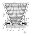
- FIG. 4 shows a lamp according to a first embodiment of the present invention. It can be seen the outlet opening 4, the inlet opening 6 and the reflector inner side 8, are arranged on the facets 10. In the inlet opening 6, the LED 14 protrudes, which is fixed to the base part 12. It can be seen, however, that the reflector contact surface 22 is no longer arranged at the same height as the inlet opening 6, but in the longitudinal direction L between the inlet opening and the outlet opening 4. Therefore, the base contact surface 24 of the base member 12 is offset accordingly.
- the reflector 2 has portions which are arranged lower than the reflector contact surface 22, for example a bottom surface 28 surrounding the inlet opening 6.
- Inventive design of the reflector which is shaped so that a projection of the at least one reflector contact surface 22 in the longitudinal direction L of the reflector 2 is undercuts.
- two webs 26 are further arranged, which each have a groove 20, engage in the biasing means 18 on holding elements 16. However, these serve only to exert a biasing force on the reflector 2 and to keep it in its defined by the reflector contact surface 22 and the base contact surface 24.
- these elements On the orientation of the reflector 2 relative to the LED 14, these elements have no influence.
- FIG. 4 In addition, a longitudinal extent D of the reflector 2 and a distance d is shown, which is the distance between the groove 20 and the inlet opening 6. It can be seen that the distance d is small in comparison to the longitudinal extent D. As a result, a high mechanical stability is achieved.
- a gap 30, which can be used for example for cooling the lamp.
- biasing means 18 and the holding elements 16 are shown by way of example in the form of hook elements. Of course, other types of biasing means 18 are conceivable.
- FIG. 5 shows an enlarged section FIG. 4 . It can be clearly seen in the enlarged illustration that the extent of the gap 30 between the bottom surface 28 and the base part 12 is determined only by the reflector contact surface 22 and the base contact surface 24, but not by the contact between the biasing means 18 and the one side of the groove 20 becomes. To make it particularly clear that the bottom surface 28 is unsuitable for such an arrangement, it is wavy and slightly bevelled.
- FIG. 6 shows the reflector 2 from the FIGS. 4 and 5 in a schematic 3D view.
- the irregularly shaped bottom surface 28 which surrounds the inlet opening 6 is not suitable due to its irregular shape and contour for an exact positioning of the reflector 2 relative to the LED 14 of the base part 12.
- For the reflector contact surfaces 22 are provided on the underside of the webs 26. In the webs 26 are again the grooves 20, can engage in the biasing elements 18. It is preferred only for contact between the biasing means 18 and the groove 20 on a side wall of the groove 20 in order to avoid mechanical over-determination of the system.
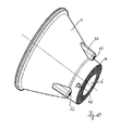
- FIG. 7 shows the reflector 2 for a further embodiment of the present invention in a schematic 3D view.
- the bottom surface 28 surrounds the inlet opening 6 of the reflector 2.
- reflector 2 has the in FIG. 7 shown reflector 2 via a circumferential reflector contact surface 22.
- the reflector 2 can be connected in any angular orientation with the corresponding base member 12. Accordingly, the reflector 2 does not have individual webs 26, but a circumferential bulge 32. This can also be seen as a single circumferential ridge become. In this, the now also circumferential groove 20 is introduced, can engage in the arranged on the base member 12 biasing means 18. At the bottom of the bulge 32 is the flat and smooth pressed reflector contact surface 22.
- the reflector contact surface 22 lies circumferentially on this base contact surface 24.
- the reflector contact surface 22 is not affected in a hot-punch method, where the inlet opening 6 is introduced into the bottom surface 28, if necessary.
- this reflector contact surface 22 is located in the longitudinal direction L directly below the reflector contact surface 22 no further part of the reflector 2, so that the projection of the at least one reflector contact surface 22 in the longitudinal direction L of the reflector 2 is undercuts.
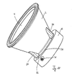
- FIG. 8 shows the reflector 2 FIG. 7 in a schematic side view in conjunction with the base part 12.
- the inlet opening 6 in which the LED 14 projects into the annular bottom surface 28 can be seen, the contour of which is irrelevant to the positioning of the reflector 2.
- the circumferential groove 20, in which the biasing means 18, which are arranged on the holding elements 16, engage may be a plurality of hooks distributed over the circumference, which are arranged at certain distances on the base part 12 and engage in the annular groove 20.
- the groove 20 does not have to be completely circumferential.
- biasing means 18 are intended to engage in the groove 20 is formed.
- FIG. 8 suggested rotational symmetry of the reflector 2 and the base member 12 is only preferred, for the present invention, however, not necessary.
- FIG. 8 is again clearly the gap 30 between the bottom surface 28 and the base part 12 recognizable. Again, the contact between the biasing means 18 and the groove 20 for the positioning of the reflector relative to the LED is not crucial, but holds the reflector only in its defined by the reflector contact surface 22 and the base contact surface 24 position.
- FIG. 9 shows a schematic sectional view through a lamp according to another embodiment of the present invention.
- the biasing means 18 are no longer integrally formed with the base member 12 are rather pins 34 which are mounted spring-loaded in holes 36 provided by spring elements.
- the pins 34 are pressed against the spring elements 38 to the outside and only snap back when the pins 34 can engage in recesses 40 provided for this purpose. Again, however, it comes only to a bias, so that a force is exerted on the reflector 2.
- the at least one reflector contact surface 22 and the at least one base contact surface 24 are pressed against one another.
- FIG. 10 shows the reflector FIG. 9 in a schematic 3D view.
- the reflector 2 has three webs 26, two of which are shown. The webs are arranged offset by 120 ° from each other on the outside of the reflector 2. On its underside are the reflector contact surfaces 22, which are pressed smooth. At the reflector neck are the recesses 40, in which the in FIG. 9 shown pins 34 which serve as biasing means 18, can engage. Also in this embodiment shown, the bottom surface 28 is irrelevant to the positioning of the reflector 2 relative to the LED 14.
- FIG. 11 shows the reflector 2 FIG. 10 which is connected to the base part 12.
- the reflector 2 has three webs 26, on each of which a reflector contact surface 22 is provided.
- the base part 12, however, has a circumferential base contact surface 24th
- FIG. 12 shows a schematic view of the reflector 2 for a further embodiment of the present invention.
- the difference from the previously shown reflector 2 consists in a recess 42 into which a provided on the base member 12 pin element can engage.
- the reflector 2 may have a plurality of these recesses 42, which are for example distributed equidistantly over its circumference.
- the corresponding pin elements on the base part 12 engage in the recesses 42, so that the two components can be connected and biased in the manner of a bayonet closure.
- the recess 42 is located in a reflector neck, which is further down, ie further to the inlet opening 6, as the reflector contact surfaces 22. Nevertheless, located directly below these reflector contact surfaces 22, ie within the projection in the longitudinal direction L of the reflector 2, no reflector component, so that this projection is also free of undercuts.
Landscapes
- Engineering & Computer Science (AREA)
- General Engineering & Computer Science (AREA)
- Chemical & Material Sciences (AREA)
- Materials Engineering (AREA)
- Organic Chemistry (AREA)
- Manufacturing & Machinery (AREA)
- Fastening Of Light Sources Or Lamp Holders (AREA)
- Securing Globes, Refractors, Reflectors Or The Like (AREA)
- Non-Portable Lighting Devices Or Systems Thereof (AREA)
- Led Device Packages (AREA)
Applications Claiming Priority (1)
| Application Number | Priority Date | Filing Date | Title |
|---|---|---|---|
| DE102012009539.2A DE102012009539B4 (de) | 2012-03-29 | 2012-03-29 | Leuchte |
Publications (2)
| Publication Number | Publication Date |
|---|---|
| EP2644979A2 true EP2644979A2 (fr) | 2013-10-02 |
| EP2644979A3 EP2644979A3 (fr) | 2014-11-12 |
Family
ID=47901753
Family Applications (1)
| Application Number | Title | Priority Date | Filing Date |
|---|---|---|---|
| EP13001393.1A Withdrawn EP2644979A3 (fr) | 2012-03-29 | 2013-03-18 | Lampe, réflecteur pour lampe et procédé de fabrication du réflecteur |
Country Status (5)
| Country | Link |
|---|---|
| US (1) | US9028107B2 (fr) |
| EP (1) | EP2644979A3 (fr) |
| JP (1) | JP5951546B2 (fr) |
| CN (1) | CN103363446B (fr) |
| DE (1) | DE102012009539B4 (fr) |
Families Citing this family (9)
| Publication number | Priority date | Publication date | Assignee | Title |
|---|---|---|---|---|
| DE102014101403A1 (de) * | 2013-05-15 | 2014-11-20 | Seidel GmbH & Co. KG | Leuchtvorrichtung |
| WO2015156986A1 (fr) * | 2014-04-07 | 2015-10-15 | 3M Innovative Properties Company | Réseaux de pavillons lumineux pour systèmes d'éclairage canalisé |
| KR101601531B1 (ko) * | 2014-11-07 | 2016-03-10 | 주식회사 지엘비젼 | 조명장치 |
| JPWO2017002267A1 (ja) * | 2015-07-02 | 2018-04-05 | パイオニア株式会社 | 光反射装置及び発光装置 |
| DE102016202571A1 (de) * | 2016-02-19 | 2017-08-24 | Osram Gmbh | Beleuchtungseinrichtung |
| DE202016001576U1 (de) | 2016-03-09 | 2016-05-12 | Günther Rösch | Beweglicher Wehrständer zur Wasserabflussregulierung als Aufsatz für bestehende Wehre, insbesondere zur Stauhaltung bei Wasserkraftwerken |
| JP2018069912A (ja) * | 2016-10-28 | 2018-05-10 | 三菱電機株式会社 | ドライバモニタリング装置 |
| US10655821B2 (en) | 2018-05-18 | 2020-05-19 | Lumileds Llc | LED device holder, LED lighting system, and method of manufacture |
| WO2024111079A1 (fr) * | 2022-11-24 | 2024-05-30 | 三菱電機株式会社 | Dispositif d'imagerie de cabine de véhicule |
Citations (8)
| Publication number | Priority date | Publication date | Assignee | Title |
|---|---|---|---|---|
| US20040264200A1 (en) | 2003-06-26 | 2004-12-30 | Asahi Techno Glass Corporation | Glass reflector for projector and manufacturing method for the same |
| JP2007220465A (ja) * | 2006-02-16 | 2007-08-30 | Stanley Electric Co Ltd | Led照明灯具 |
| EP1961708A1 (fr) | 2007-01-24 | 2008-08-27 | Schott AG | Procédé destiné à la fabrication de réflecteurs en verre ou en vitrocéramique |
| US20110019409A1 (en) | 2009-07-21 | 2011-01-27 | Cooper Technologies Company | Interfacing a Light Emitting Diode (LED) Module to a Heat Sink Assembly, a Light Reflector and Electrical Circuits |
| DE102009047493A1 (de) | 2009-12-04 | 2011-06-09 | Osram Gesellschaft mit beschränkter Haftung | Leuchtvorrichtung und Aufsatzelement zur Befestigung an der Leuchtvorrichtung |
| WO2011104255A1 (fr) | 2010-02-23 | 2011-09-01 | Zumtobel Lighting Gmbh | Plafonnier sans cadre |
| DE102010031312A1 (de) | 2010-07-14 | 2012-01-19 | Osram Ag | Befestigungselement, Leuchtmodul und Leuchtvorrichtung |
| WO2012115840A2 (fr) | 2011-02-24 | 2012-08-30 | Rambus Inc. | Détection de problème de retard pour des e/s de puce |
Family Cites Families (13)
| Publication number | Priority date | Publication date | Assignee | Title |
|---|---|---|---|---|
| US3662165A (en) * | 1970-03-02 | 1972-05-09 | Gen Electric | Luminaire reflector |
| US3700882A (en) * | 1970-09-02 | 1972-10-24 | Jean Planchon | Faceted reflector |
| US4021659A (en) * | 1975-10-30 | 1977-05-03 | General Electric Company | Projector lamp reflector |
| US4447865A (en) * | 1982-05-13 | 1984-05-08 | General Electric Company | Reflector lamp |
| US6080464A (en) * | 1995-11-20 | 2000-06-27 | Heraeus Med Gmbh | Reflector for a radiating luminous source and use of the same |
| JP2004093623A (ja) * | 2002-08-29 | 2004-03-25 | Olympus Corp | 照明装置及びそれを用いた表示装置 |
| WO2007049206A1 (fr) * | 2005-10-26 | 2007-05-03 | Koninklijke Philips Electronics N.V. | Lampe électrique et/ou unité de réflecteur avec un réflecteur moulé |
| DE102006038382A1 (de) * | 2006-08-15 | 2008-02-28 | Schott Ag | Reflektor für Gasentladungslampen |
| CN201034290Y (zh) * | 2007-04-06 | 2008-03-12 | 鹤山丽得电子实业有限公司 | 一种聚光led照明灯 |
| CN201666538U (zh) * | 2010-02-12 | 2010-12-08 | 胡震海 | 手电筒反光杯 |
| JP4590489B1 (ja) * | 2010-07-09 | 2010-12-01 | シーシーエス株式会社 | ライン光照射装置 |
| US8240887B2 (en) * | 2010-08-27 | 2012-08-14 | Tyco Electronics Corporation | LED light module |
| WO2012158404A1 (fr) * | 2011-05-13 | 2012-11-22 | Cooper Technologies Company | Réflecteurs et fixations de réflecteurs utilisés dans des sources de lumière à diodes électroluminescentes (led) |
-
2012
- 2012-03-29 DE DE102012009539.2A patent/DE102012009539B4/de not_active Expired - Fee Related
-
2013
- 2013-03-15 US US13/832,117 patent/US9028107B2/en active Active
- 2013-03-18 EP EP13001393.1A patent/EP2644979A3/fr not_active Withdrawn
- 2013-03-28 CN CN201310104694.9A patent/CN103363446B/zh not_active Expired - Fee Related
- 2013-03-29 JP JP2013072976A patent/JP5951546B2/ja not_active Expired - Fee Related
Patent Citations (8)
| Publication number | Priority date | Publication date | Assignee | Title |
|---|---|---|---|---|
| US20040264200A1 (en) | 2003-06-26 | 2004-12-30 | Asahi Techno Glass Corporation | Glass reflector for projector and manufacturing method for the same |
| JP2007220465A (ja) * | 2006-02-16 | 2007-08-30 | Stanley Electric Co Ltd | Led照明灯具 |
| EP1961708A1 (fr) | 2007-01-24 | 2008-08-27 | Schott AG | Procédé destiné à la fabrication de réflecteurs en verre ou en vitrocéramique |
| US20110019409A1 (en) | 2009-07-21 | 2011-01-27 | Cooper Technologies Company | Interfacing a Light Emitting Diode (LED) Module to a Heat Sink Assembly, a Light Reflector and Electrical Circuits |
| DE102009047493A1 (de) | 2009-12-04 | 2011-06-09 | Osram Gesellschaft mit beschränkter Haftung | Leuchtvorrichtung und Aufsatzelement zur Befestigung an der Leuchtvorrichtung |
| WO2011104255A1 (fr) | 2010-02-23 | 2011-09-01 | Zumtobel Lighting Gmbh | Plafonnier sans cadre |
| DE102010031312A1 (de) | 2010-07-14 | 2012-01-19 | Osram Ag | Befestigungselement, Leuchtmodul und Leuchtvorrichtung |
| WO2012115840A2 (fr) | 2011-02-24 | 2012-08-30 | Rambus Inc. | Détection de problème de retard pour des e/s de puce |
Also Published As
| Publication number | Publication date |
|---|---|
| DE102012009539B4 (de) | 2020-12-24 |
| DE102012009539A1 (de) | 2013-10-17 |
| US9028107B2 (en) | 2015-05-12 |
| JP2013206885A (ja) | 2013-10-07 |
| US20130258674A1 (en) | 2013-10-03 |
| JP5951546B2 (ja) | 2016-07-13 |
| CN103363446A (zh) | 2013-10-23 |
| EP2644979A3 (fr) | 2014-11-12 |
| CN103363446B (zh) | 2015-07-08 |
Similar Documents
| Publication | Publication Date | Title |
|---|---|---|
| DE102012009539B4 (de) | Leuchte | |
| AT514403B1 (de) | Beleuchtungsvorrichtung für einen Fahrzeugscheinwerfer sowie Fahrzeugscheinwerfer | |
| DE102004001312B4 (de) | Chip-Leuchtdiode und Verfahren zu ihrer Herstellung | |
| DE102013103751B4 (de) | Verfahren zur Herstellung von hochmaßhaltigen Halbschalen und Vorrichtung zur Herstellung einer Halbschale | |
| DE112011102050B4 (de) | Herstellungsverfahren und Herstellungsvorrichtung für mit Nabe versehenes scheibenförmiges Bauteil | |
| DE102010040547A1 (de) | Bauteilverbindung | |
| EP2414727A1 (fr) | Dispositif lumineux et luminaire présentant un tel dispositif lumineux | |
| DE3610675C2 (de) | Verfahren und Vorrichtung zum Anbringen eines Hohlkörpers an einem tafelförmigen Werkstück | |
| DE102007038786B4 (de) | Vorsatzlinse eines Leuchtmoduls, Leuchtmodul und Herstellungsverfahren | |
| EP3508737B1 (fr) | Dispositif de raccordement pour composants de phare | |
| DE102019114306A1 (de) | Drosselventil für eine Abgasvorrichtung, insbesondere für eine Kraftfahrzeugabgasvorrichtung | |
| EP2060336A1 (fr) | Outil de coupe et bordage de pièces usinées plates, ainsi que procédé de coupe et de bordage | |
| AT523669B1 (de) | LED-Modul mit Silikonlinse | |
| EP1857197B1 (fr) | Matrice pour réaliser un assemblage mécanique | |
| EP1559488B1 (fr) | Procédé de fabrication d'eléments creux ainsi outil à suivre pour la mise en oeuvre de ce procédé. | |
| BE1025851B1 (de) | Borstenträger, Bürste sowie Verfahren und Vorrichtung zur Herstellung von Bürsten | |
| DE102009020476B3 (de) | Verfahren zum Herstellen gekrümmter Spiegelfacetten | |
| DE60013103T2 (de) | Verfahren, Vorrichtung und Werkstück zur Herstellung eines Wärmeübertragungsteils | |
| EP3088796B1 (fr) | Rail profile destine au positionnement de modules a del dans des condensateurs lumineux | |
| EP2873910A1 (fr) | Instrument optique d'éclairage et bandeau lumineux | |
| WO2020114703A1 (fr) | Procédé de formage à chaud d'un demi-produit, notamment plat | |
| EP2920513B1 (fr) | Luminaire et procédé de fabrication d'un luminaire | |
| EP3418631A1 (fr) | Corps de refroidissement pour un moyen d'éclairage de del et procédé de fabrication de corps de refroidissement | |
| EP3064827B1 (fr) | Arrangement d'un montage d'un module led sur une surface d'un corps de refroidissement et montage led | |
| DE10225618A1 (de) | Verfahren zur Herstellung von Bauteilen mit langgestreckten Strukturen |
Legal Events
| Date | Code | Title | Description |
|---|---|---|---|
| PUAI | Public reference made under article 153(3) epc to a published international application that has entered the european phase |
Free format text: ORIGINAL CODE: 0009012 |
|
| AK | Designated contracting states |
Kind code of ref document: A2 Designated state(s): AL AT BE BG CH CY CZ DE DK EE ES FI FR GB GR HR HU IE IS IT LI LT LU LV MC MK MT NL NO PL PT RO RS SE SI SK SM TR |
|
| AX | Request for extension of the european patent |
Extension state: BA ME |
|
| PUAL | Search report despatched |
Free format text: ORIGINAL CODE: 0009013 |
|
| AK | Designated contracting states |
Kind code of ref document: A3 Designated state(s): AL AT BE BG CH CY CZ DE DK EE ES FI FR GB GR HR HU IE IS IT LI LT LU LV MC MK MT NL NO PL PT RO RS SE SI SK SM TR |
|
| AX | Request for extension of the european patent |
Extension state: BA ME |
|
| RIC1 | Information provided on ipc code assigned before grant |
Ipc: F21V 17/14 20060101ALI20141008BHEP Ipc: F21V 17/16 20060101ALI20141008BHEP Ipc: F21Y 101/02 20060101ALI20141008BHEP Ipc: F21V 7/00 20060101AFI20141008BHEP Ipc: F21V 7/22 20060101ALI20141008BHEP |
|
| 17P | Request for examination filed |
Effective date: 20141231 |
|
| RBV | Designated contracting states (corrected) |
Designated state(s): AL AT BE BG CH CY CZ DE DK EE ES FI FR GB GR HR HU IE IS IT LI LT LU LV MC MK MT NL NO PL PT RO RS SE SI SK SM TR |
|
| STAA | Information on the status of an ep patent application or granted ep patent |
Free format text: STATUS: EXAMINATION IS IN PROGRESS |
|
| 17Q | First examination report despatched |
Effective date: 20170120 |
|
| STAA | Information on the status of an ep patent application or granted ep patent |
Free format text: STATUS: THE APPLICATION IS DEEMED TO BE WITHDRAWN |
|
| 18D | Application deemed to be withdrawn |
Effective date: 20211001 |