EP2645014B1 - Climatiseur - Google Patents
Climatiseur Download PDFInfo
- Publication number
- EP2645014B1 EP2645014B1 EP11842473.8A EP11842473A EP2645014B1 EP 2645014 B1 EP2645014 B1 EP 2645014B1 EP 11842473 A EP11842473 A EP 11842473A EP 2645014 B1 EP2645014 B1 EP 2645014B1
- Authority
- EP
- European Patent Office
- Prior art keywords
- heat medium
- heat
- heat exchanger
- refrigerant
- air
- Prior art date
- Legal status (The legal status is an assumption and is not a legal conclusion. Google has not performed a legal analysis and makes no representation as to the accuracy of the status listed.)
- Active
Links
Images





Classifications
-
- F—MECHANICAL ENGINEERING; LIGHTING; HEATING; WEAPONS; BLASTING
- F24—HEATING; RANGES; VENTILATING
- F24F—AIR-CONDITIONING; AIR-HUMIDIFICATION; VENTILATION; USE OF AIR CURRENTS FOR SCREENING
- F24F3/00—Air-conditioning systems in which conditioned primary air is supplied from one or more central stations to distributing units in the rooms or spaces where it may receive secondary treatment; Apparatus specially designed for such systems
- F24F3/06—Air-conditioning systems in which conditioned primary air is supplied from one or more central stations to distributing units in the rooms or spaces where it may receive secondary treatment; Apparatus specially designed for such systems characterised by the arrangements for the supply of heat-exchange fluid for the subsequent treatment of primary air in the room units
- F24F3/08—Air-conditioning systems in which conditioned primary air is supplied from one or more central stations to distributing units in the rooms or spaces where it may receive secondary treatment; Apparatus specially designed for such systems characterised by the arrangements for the supply of heat-exchange fluid for the subsequent treatment of primary air in the room units with separate supply and return lines for hot and cold heat-exchange fluids i.e. so-called "4-conduit" system
-
- F—MECHANICAL ENGINEERING; LIGHTING; HEATING; WEAPONS; BLASTING
- F24—HEATING; RANGES; VENTILATING
- F24F—AIR-CONDITIONING; AIR-HUMIDIFICATION; VENTILATION; USE OF AIR CURRENTS FOR SCREENING
- F24F3/00—Air-conditioning systems in which conditioned primary air is supplied from one or more central stations to distributing units in the rooms or spaces where it may receive secondary treatment; Apparatus specially designed for such systems
- F24F3/06—Air-conditioning systems in which conditioned primary air is supplied from one or more central stations to distributing units in the rooms or spaces where it may receive secondary treatment; Apparatus specially designed for such systems characterised by the arrangements for the supply of heat-exchange fluid for the subsequent treatment of primary air in the room units
-
- F—MECHANICAL ENGINEERING; LIGHTING; HEATING; WEAPONS; BLASTING
- F25—REFRIGERATION OR COOLING; COMBINED HEATING AND REFRIGERATION SYSTEMS; HEAT PUMP SYSTEMS; MANUFACTURE OR STORAGE OF ICE; LIQUEFACTION SOLIDIFICATION OF GASES
- F25B—REFRIGERATION MACHINES, PLANTS OR SYSTEMS; COMBINED HEATING AND REFRIGERATION SYSTEMS; HEAT PUMP SYSTEMS
- F25B13/00—Compression machines, plants or systems, with reversible cycle
-
- F—MECHANICAL ENGINEERING; LIGHTING; HEATING; WEAPONS; BLASTING
- F25—REFRIGERATION OR COOLING; COMBINED HEATING AND REFRIGERATION SYSTEMS; HEAT PUMP SYSTEMS; MANUFACTURE OR STORAGE OF ICE; LIQUEFACTION SOLIDIFICATION OF GASES
- F25B—REFRIGERATION MACHINES, PLANTS OR SYSTEMS; COMBINED HEATING AND REFRIGERATION SYSTEMS; HEAT PUMP SYSTEMS
- F25B25/00—Machines, plants or systems, using a combination of modes of operation covered by two or more of the groups F25B1/00 - F25B23/00
- F25B25/005—Machines, plants or systems, using a combination of modes of operation covered by two or more of the groups F25B1/00 - F25B23/00 using primary and secondary systems
-
- F—MECHANICAL ENGINEERING; LIGHTING; HEATING; WEAPONS; BLASTING
- F25—REFRIGERATION OR COOLING; COMBINED HEATING AND REFRIGERATION SYSTEMS; HEAT PUMP SYSTEMS; MANUFACTURE OR STORAGE OF ICE; LIQUEFACTION SOLIDIFICATION OF GASES
- F25D—REFRIGERATORS; COLD ROOMS; ICE-BOXES; COOLING OR FREEZING APPARATUS NOT OTHERWISE PROVIDED FOR
- F25D17/00—Arrangements for circulating cooling fluids; Arrangements for circulating gas, e.g. air, within refrigerated spaces
- F25D17/02—Arrangements for circulating cooling fluids; Arrangements for circulating gas, e.g. air, within refrigerated spaces for circulating liquids, e.g. brine
-
- F—MECHANICAL ENGINEERING; LIGHTING; HEATING; WEAPONS; BLASTING
- F24—HEATING; RANGES; VENTILATING
- F24F—AIR-CONDITIONING; AIR-HUMIDIFICATION; VENTILATION; USE OF AIR CURRENTS FOR SCREENING
- F24F3/00—Air-conditioning systems in which conditioned primary air is supplied from one or more central stations to distributing units in the rooms or spaces where it may receive secondary treatment; Apparatus specially designed for such systems
- F24F3/06—Air-conditioning systems in which conditioned primary air is supplied from one or more central stations to distributing units in the rooms or spaces where it may receive secondary treatment; Apparatus specially designed for such systems characterised by the arrangements for the supply of heat-exchange fluid for the subsequent treatment of primary air in the room units
- F24F3/065—Air-conditioning systems in which conditioned primary air is supplied from one or more central stations to distributing units in the rooms or spaces where it may receive secondary treatment; Apparatus specially designed for such systems characterised by the arrangements for the supply of heat-exchange fluid for the subsequent treatment of primary air in the room units with a plurality of evaporators or condensers
-
- F—MECHANICAL ENGINEERING; LIGHTING; HEATING; WEAPONS; BLASTING
- F25—REFRIGERATION OR COOLING; COMBINED HEATING AND REFRIGERATION SYSTEMS; HEAT PUMP SYSTEMS; MANUFACTURE OR STORAGE OF ICE; LIQUEFACTION SOLIDIFICATION OF GASES
- F25B—REFRIGERATION MACHINES, PLANTS OR SYSTEMS; COMBINED HEATING AND REFRIGERATION SYSTEMS; HEAT PUMP SYSTEMS
- F25B2313/00—Compression machines, plants or systems with reversible cycle not otherwise provided for
- F25B2313/023—Compression machines, plants or systems with reversible cycle not otherwise provided for using multiple indoor units
- F25B2313/0231—Compression machines, plants or systems with reversible cycle not otherwise provided for using multiple indoor units with simultaneous cooling and heating
-
- F—MECHANICAL ENGINEERING; LIGHTING; HEATING; WEAPONS; BLASTING
- F25—REFRIGERATION OR COOLING; COMBINED HEATING AND REFRIGERATION SYSTEMS; HEAT PUMP SYSTEMS; MANUFACTURE OR STORAGE OF ICE; LIQUEFACTION SOLIDIFICATION OF GASES
- F25B—REFRIGERATION MACHINES, PLANTS OR SYSTEMS; COMBINED HEATING AND REFRIGERATION SYSTEMS; HEAT PUMP SYSTEMS
- F25B2313/00—Compression machines, plants or systems with reversible cycle not otherwise provided for
- F25B2313/027—Compression machines, plants or systems with reversible cycle not otherwise provided for characterised by the reversing means
- F25B2313/0272—Compression machines, plants or systems with reversible cycle not otherwise provided for characterised by the reversing means using bridge circuits of one-way valves
-
- F—MECHANICAL ENGINEERING; LIGHTING; HEATING; WEAPONS; BLASTING
- F25—REFRIGERATION OR COOLING; COMBINED HEATING AND REFRIGERATION SYSTEMS; HEAT PUMP SYSTEMS; MANUFACTURE OR STORAGE OF ICE; LIQUEFACTION SOLIDIFICATION OF GASES
- F25B—REFRIGERATION MACHINES, PLANTS OR SYSTEMS; COMBINED HEATING AND REFRIGERATION SYSTEMS; HEAT PUMP SYSTEMS
- F25B2313/00—Compression machines, plants or systems with reversible cycle not otherwise provided for
- F25B2313/027—Compression machines, plants or systems with reversible cycle not otherwise provided for characterised by the reversing means
- F25B2313/02732—Compression machines, plants or systems with reversible cycle not otherwise provided for characterised by the reversing means using two three-way valves
-
- F—MECHANICAL ENGINEERING; LIGHTING; HEATING; WEAPONS; BLASTING
- F25—REFRIGERATION OR COOLING; COMBINED HEATING AND REFRIGERATION SYSTEMS; HEAT PUMP SYSTEMS; MANUFACTURE OR STORAGE OF ICE; LIQUEFACTION SOLIDIFICATION OF GASES
- F25B—REFRIGERATION MACHINES, PLANTS OR SYSTEMS; COMBINED HEATING AND REFRIGERATION SYSTEMS; HEAT PUMP SYSTEMS
- F25B2313/00—Compression machines, plants or systems with reversible cycle not otherwise provided for
- F25B2313/027—Compression machines, plants or systems with reversible cycle not otherwise provided for characterised by the reversing means
- F25B2313/02741—Compression machines, plants or systems with reversible cycle not otherwise provided for characterised by the reversing means using one four-way valve
-
- F—MECHANICAL ENGINEERING; LIGHTING; HEATING; WEAPONS; BLASTING
- F25—REFRIGERATION OR COOLING; COMBINED HEATING AND REFRIGERATION SYSTEMS; HEAT PUMP SYSTEMS; MANUFACTURE OR STORAGE OF ICE; LIQUEFACTION SOLIDIFICATION OF GASES
- F25B—REFRIGERATION MACHINES, PLANTS OR SYSTEMS; COMBINED HEATING AND REFRIGERATION SYSTEMS; HEAT PUMP SYSTEMS
- F25B2339/00—Details of evaporators; Details of condensers
- F25B2339/04—Details of condensers
- F25B2339/047—Water-cooled condensers
Definitions
- the present invention relates to an air-conditioning apparatus that is applied to, for example, a multi-air-conditioning apparatus for an office building.
- a conventional air-conditioning apparatus such as a multi-air-conditioning apparatus for an office building, performs a cooling operation or a heating operation by, for example, circulating a refrigerant between an outdoor unit, which is a heat source unit disposed outside of a structure, and indoor units disposed inside of a structure. Specifically, a conditioned space is cooled with air that has been cooled by a refrigerant removing heat from air and is heated with air that has been heated by the refrigerant transferring its heat.
- HFC hydrofluorocarbon
- An air-conditioning apparatus has also been developed which uses a natural refrigerant, such as carbon dioxide (CO2).
- cooling energy or heating energy is generated in a heat source unit disposed outside of a structure.
- Water, antifreeze, or the like is heated or cooled by a heat exchanger disposed in an outdoor unit, and conveyed to an indoor unit, such as a fan coil unit or a panel heater. And thereby, heating or cooling is performed (refer to Patent Literature 1, for example).
- An air-conditioning apparatus called a heat recovery chiller is constituted such that a heat source unit is connected to each indoor unit by four water pipes arranged therebetween and, cooled water and heated water and the like are simultaneously supplied so that cooling or heating can be freely selected in indoor units (refer to Patent Literature 2, for example).
- an air-conditioning apparatus has been developed in which a heat exchanger for a primary refrigerant and a secondary refrigerant is disposed near each indoor unit to convey the secondary refrigerant to the indoor units (refer to Patent Literature 3, for example).
- an air-conditioning apparatus which is constituted such that an outdoor unit is connected to each branch unit including a heat exchanger by two pipes to convey a secondary refrigerant to an indoor unit (refer to Patent Literature 4, for example). Further relevant air conditioning apparatuses are disclosed in EP 0 887 599 and JP 08086477 .
- air-conditioning apparatuses such as a multi-air-conditioning apparatus for an office building, include an air-conditioning apparatus in which a refrigerant is circulated from an outdoor unit to a relay unit and a heat medium, such as water, is circulated from the relay unit to each indoor unit to reduce conveyance power for the heat medium while circulating the heat medium, such as water, through the indoor unit (refer to Patent Literature 5, for example).
- a refrigerant may leak into, for example, an indoor space because the refrigerant is circulated up to an indoor unit.
- a refrigerant is circulated only within the heat source unit disposed outdoors, and the refrigerant does not pass through the indoor unit. It is however necessary to heat or cool a heat medium in a heat source unit disposed outside of a structure and convey it to the indoor unit in the air-conditioning apparatus like those disclosed in Patent Literature 1 and Patent Literature 2. Accordingly, the circulation path for the heat medium becomes long.
- the amount of energy consumed as conveyance power and the like by the heat medium is higher than that by the refrigerant. As the circulation path becomes longer, therefore, the conveyance power markedly increases. This indicates that energy can be saved as long as the circulation of the heat medium can be properly controlled in the air-conditioning apparatus.
- Patent Literature 5 presents no problem in a case where a single refrigerant or a near-azeotropic refrigerant is used as the refrigerant, in a case where a zeotropic refrigerant mixture is used as the refrigerant, there is a possibility that when using a refrigerant-heat medium heat exchanger as an evaporator, the heat exchange performance between the refrigerant and the heat medium may decrease owing to the temperature gradient between the saturated liquid temperature and saturated gas temperature of the refrigerant.
- the invention has been made to overcome the above problems and aims to provide an air-conditioning apparatus that is capable of saving energy.
- the invention aims to provide an air-conditioning apparatus that can improve safety without circulating a refrigerant in or near an indoor unit.
- the invention aims to provide an air-conditioning apparatus that can reduce the number of connecting pipes between an outdoor unit and a branch unit (heat medium relay unit) or an indoor unit to make the construction easier, and improve energy efficiency.
- the air-conditioning apparatus according to the invention requires less conveyance power because pipes through which the heat medium circulates can be shortened, the apparatus can improve safety and save energy. In addition, even if the heat medium leaks to the outside of the air-conditioning apparatus according to the invention, the amount of the leakage can be kept small. Accordingly, the safety can be improved. Further, the air-conditioning apparatus according to the invention can improve heat transfer efficiency in the second heat exchanger, thereby further contributing to improvement of energy efficiency.
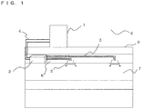
- Fig. 1 is a schematic diagram illustrating an exemplary installation of an air-conditioning apparatus according to Embodiment of the invention.
- This air-conditioning apparatus employs refrigeration cycles (a refrigerant circuit A and a heat medium circuit B) in which refrigerants (a heat source side refrigerant or a heat medium) circulate such that a cooling mode or a heating mode can be freely selected as its operation mode in each indoor unit.
- refrigerants a heat source side refrigerant or a heat medium
- the air-conditioning apparatus includes a single outdoor unit 1, functioning as a heat source unit, a plurality of indoor units 2, and a heat medium relay unit 3 disposed between the outdoor unit 1 and the indoor units 2.
- the heat medium relay unit 3 exchanges heat between the heat source side refrigerant and the heat medium.
- the outdoor unit 1 is connected to the heat medium relay unit 3 with refrigerant pipes 4 through which the heat source side refrigerant is conveyed.
- the heat medium relay unit 3 is connected to each indoor unit 2 with pipes (heat medium pipes) 5 through which the heat medium is conveyed. Cooling energy or heating energy generated in the outdoor unit 1 is delivered through the heat medium relay unit 3 to the indoor units 2.
- the outdoor unit 1 is typically disposed in an outdoor space 6 which is a space (e.g., a roof) outside of a structure 9, such as an office building, and is configured to supply cooling energy or heating energy through the heat medium relay unit 3 to the indoor units 2.
- Each indoor unit 2 is disposed at a position such that it can supply cooling air or heating air to an indoor space 7, which is a space (e.g., a living room) inside of the structure 9, and is configured to supply the cooling air or heating air to the indoor space 7, as an air-conditioned space.
- the heat medium relay unit 3 is configured with a housing separated from housings of the outdoor unit 1 and the indoor units 2 such that the heat medium relay unit 3 can be disposed at a position different from those of the outdoor space 6 and the indoor space 7, and is connected to the outdoor unit 1 through the refrigerant pipes 4 and is connected to the indoor units 2 through the pipes 5 to transfer cooling energy or heating energy supplied from the outdoor unit 1 to the indoor units 2.
- the outdoor unit 1 is connected to the heat medium relay unit 3 with two refrigerant pipes 4, and the heat medium relay unit 3 is connected to each indoor unit 2 with two pipes 5.
- each of the units (the outdoor unit 1, the indoor units 2, and the heat medium relay unit 3) is connected with two pipes (the refrigerant pipes 4 or the pipes 5), thus construction is facilitated.
- Fig. 1 illustrates a state where the heat medium relay unit 3 is disposed in the structure 9 but in a space different from the indoor space 7, for example, a space above a ceiling (hereinafter, simply referred to as a "space 8"). Therefore, other than the space above the ceiling, the heat medium relay unit 3 may be installed in any space as long as the space is not a living space and is somehow ventilated to outside. For example, it is also possible to install the heat medium relay unit 3 in a space that is a common use space where an elevator or the like is located and is ventilated to outside, or the like. Furthermore, the heat medium relay unit 3 can be disposed near the outdoor unit 1. If the distance between the heat medium relay unit 3 and each indoor unit 2 is too long, the conveyance power for the heat medium becomes considerably large. It should be therefore noted that the energy saving effect is reduced in this case.
- Fig. 1 illustrates a case in which the outdoor unit 1 is disposed in the outdoor space 6.
- the outdoor unit 1 may be disposed in an enclosed space, for example, a machine room with a ventilation opening, may be disposed inside of the structure 9 as long as waste heat can be exhausted through an exhaust duct to the outside of the structure 9, or may also be disposed inside of the structure 9 in the use of the outdoor unit 1 of a water-cooled type. There is no particular problem when the outdoor unit 1 is disposed in such a place.
- Fig. 1 illustrates a case in which the indoor units 2 are of a ceiling cassette type
- the indoor units are not limited to this type and, for example, a ceiling-concealed type, a ceiling-suspended type, or any type of indoor unit may be used as long as the unit can blow out heating air or cooling air into the indoor space 7 directly or through a duct or the like.
- the numbers of connected outdoor unit 1, indoor units 2, and heat medium relay unit 3 are not limited to those illustrated in Fig. 1 . The numbers thereof can be determined in accordance with the structure 9 where the air-conditioning apparatus according to Embodiment is installed.
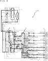
- Fig. 2 is a schematic circuit diagram illustrating an exemplary circuit configuration of the air-conditioning apparatus (hereinafter, referred to as an "air-conditioning apparatus 100") according to Embodiment.
- the detailed configuration of the air-conditioning apparatus 100 will be described with reference to Fig. 2 .
- the outdoor unit 1 and the heat medium relay unit 3 are connected with the refrigerant pipes 4 through heat exchangers 15a and 15b related to heat medium included in the heat medium relay unit 3.
- the heat medium relay unit 3 and each indoor unit 2 are also connected by the pipes 5 through the heat exchangers 15a and 15b related to heat medium. Note that the refrigerant pipes 4 will be described in detail later.
- the outdoor unit 1 includes a compressor 10, a first refrigerant flow switching device 11, such as a four-way valve, a heat source side heat exchanger 12 (first heat exchanger), and an accumulator 19, which are connected in series by the refrigerant pipes 4.
- the outdoor unit 1 further includes a first connecting pipe 4a, a second connecting pipe 4b, a check valve 13a, a check valve 13b, a check valve 13c, and a check valve 13d.
- Such an arrangement of the first connecting pipe 4a, the second connecting pipe 4b, the check valve 13a, the check valve 13b, the check valve 13c, and the check valve 13d enables the heat source side refrigerant, allowed to flow into the heat medium relay unit 3, to flow in a constant direction irrespective of an operation requested by any indoor unit 2.
- the compressor 10 is configured to suction the heat source side refrigerant and compress the heat source side refrigerant to a high temperature, high pressure state, and may be a capacity-controllable inverter compressor, for example.
- the first refrigerant flow switching device 11 is configured to switch the flow of the heat source side refrigerant between a heating operation (a heating only operation mode and a heating main operation mode) and a cooling operation (a cooling only operation mode and a cooling main operation mode).
- the heat source side heat exchanger 12 is configured to function as an evaporator in the heating operation, function as a condenser (or a radiator) in the cooling operation, exchange heat between air, supplied from an air-sending device such as a fan (not illustrated), and the heat source side refrigerant, and evaporate and gasify or condense and liquefy the heat source side refrigerant.
- the accumulator 19 is disposed on a suction side of the compressor 10 and is configured to store an excess refrigerant caused by the difference between the heating operation and the cooling operation or by transient change in operation.
- the check valve 13d is provided in the refrigerant pipe 4 positioned between the heat medium relay unit 3 and the first refrigerant flow switching device 11 and is configured to permit the heat source side refrigerant to flow only in a predetermined direction (the direction from the heat medium relay unit 3 to the outdoor unit 1).
- the check valve 13a is provided in the refrigerant pipe 4 positioned between the heat source side heat exchanger 12 and the heat medium relay unit 3 and is configured to permit the heat source side refrigerant to flow only in a predetermined direction (the direction from the outdoor unit 1 to the heat medium relay unit 3).
- the check valve 13b is provided in the first connecting pipe 4a and is configured to allow the heat source side refrigerant, discharged from the compressor 10 in the heating operation, to flow to the heat medium relay unit 3.
- the check valve 13c is provided in the second connecting pipe 4b and is configured to allow the heat source side refrigerant, returned from the heat medium relay unit 3 in the heating operation, to flow to the suction side of the compressor 10.
- the first connecting pipe 4a is configured to connect the refrigerant pipe 4, positioned between the first refrigerant flow switching device 11 and the check valve 13d, to the refrigerant pipe 4, positioned between the check valve 13a and the heat medium relay unit 3, in the outdoor unit 1.
- the second connecting pipe 4b is configured to connect the refrigerant pipe 4, positioned between the check valve 13d and the heat medium relay unit 3, to the refrigerant pipe 4, positioned between the heat source side heat exchanger 12 and the check valve 13a, in the outdoor unit 1.
- FIG 2 illustrates a case where the first connecting pipe 4a, the second connecting pipe 4b, the check valve 13a, the check valve 13b, the check valve 13c, and the check valve 13d are arranged, but the arrangement is not limited to this case. It is not necessarily required to arrange these components.
- the indoor units 2 each include a use side heat exchanger (third heat exchanger) 26.
- Each of the use side heat exchangers 26 is connected by the pipes 5 to a heat medium flow control device 25 and a second heat medium flow switching device 23 arranged in the heat medium relay unit 3.
- Each of the use side heat exchangers 26 is configured to exchange heat between air supplied from an air-sending device, such as a fan (not illustrated), and the heat medium in order to generate heating air or cooling air to be supplied to the indoor space 7.
- Fig. 2 illustrates a case in which four indoor units 2 are connected to the heat medium relay unit 3. Illustrated are, from the bottom of the drawing, an indoor unit 2a, an indoor unit 2b, an indoor unit 2c, and an indoor unit 2d.
- the use side heat exchangers 26 are illustrated as, from the bottom of the drawing, a use side heat exchanger 26a, a use side heat exchanger 26b, a use side heat exchanger 26c, and a use side heat exchanger 26d each corresponding to the indoor units 2a to 2d.
- the number of connected indoor units 2 illustrated in Fig. 2 is not limited to four.
- the heat medium relay unit 3 includes the two heat exchangers 15 related to heat medium (second heat exchangers), two expansion devices 16, two opening and closing devices 17, two second refrigerant flow switching devices 18, two pumps 21, four heat medium flow reversing devices 20, four first heat medium flow switching devices 22, the four second heat medium flow control devices 23, and the four heat medium flow control devices 25.
- Each of the two heat exchangers 15 related to heat medium functions as a condenser (radiator) or an evaporator and exchanges heat between the heat source side refrigerant and the heat medium in order to transfer cooling energy or heating energy, generated in the outdoor unit 1 and stored in the heat source side refrigerant, to the heat medium.
- the heat exchanger 15a related to heat medium is disposed between an expansion device 16a and a second refrigerant flow switching device 18a in the refrigerant circuit A and is used to cool the heat medium in the cooling and heating mixed operation mode.
- the heat exchanger 15b related to heat medium is disposed between an expansion device 16b and a second refrigerant flow switching device 18b in the refrigerant circuit A and is used to heat the heat medium in the cooling and heating mixed operation mode.
- the two expansion devices 16 each have functions as a reducing valve and an expansion valve and are configured to reduce the pressure of the heat source side refrigerant in order to expand it.
- the expansion device 16a is disposed upstream from the heat exchanger 15a related to heat medium in the flow direction of the heat source side refrigerant during the cooling operation.
- the expansion device 16b is disposed upstream from the heat exchanger 15b related to heat medium in the flow direction of the heat source side refrigerant during the cooling operation.
- Each of the two expansion devices 16 may include a component having a variably controllable opening degree, for example, an electronic expansion valve.
- the two opening and closing devices 17 each include a two-way valve and the like, and are configured to open or close the refrigerant pipe 4.
- the opening and closing device 17a is disposed in the refrigerant pipe 4 on the inlet side of the heat source side refrigerant.
- the opening and closing device 17b is disposed in a pipe connecting the refrigerant pipe 4 on the inlet side for the heat source side refrigerant and the refrigerant pipe 4 on an outlet side therefor.
- the two second refrigerant flow switching devices 18 each include a four-way valve, for example, and are configured to switch the flow direction of the heat source side refrigerant in accordance with an operation mode.
- the second refrigerant flow switching device 18a is disposed downstream from the heat exchanger 15a related to heat medium in the flow direction of the heat source side refrigerant during the cooling operation.
- the second refrigerant flow switching device 18b is disposed downstream from the heat exchanger 15b related to heat medium in the flow direction of the heat source side refrigerant in the cooling only operation mode.
- the two pumps 21 are configured to circulate the heat medium conveyed through the pipes 5.
- the pump 21a is disposed in the pipe 5 positioned between heat exchanger 15a related to heat medium and the second heat medium flow switching devices 23.
- the pump 21b is disposed in the pipe 5 between the heat exchanger 15b related to heat medium and the second heat medium flow switching devices 23.
- Each of the two pumps 21 may be, for example, a capacity-controllable pump such that a flow rate in the pump can be controlled in accordance with the magnitude of loads in the indoor units 2.
- the four heat medium flow reversing devices 20 each include a three-way valve, for example, and switch the flow direction of the heat medium concerning the heat exchanger 15a related to heat medium and the heat exchanger 15b related to heat medium.
- Two heat medium flow reversing devices 20 are installed for each heat exchanger 15 related to heat medium.
- the heat medium flow reversing device (first heat medium flow reversing device) 20a and the heat medium flow reversing device (second heat medium flow reversing device) 20b are installed for the heat exchanger 15a related to heat medium
- the heat medium flow reversing device (first heat medium flow reversing device) 20c and the heat medium flow reversing device (second heat medium flow reversing device) 20d are installed for the heat exchanger 15b related to heat medium.
- one of the three ways is connected by a pipe to the pump (heat medium sending device) 21a, another one of the three ways is connected by a pipe to one end of the heat exchanger 15a related to heat medium, and the other one of the three ways is connected by a pipe to a first connection port in the passage between the other end of the heat exchanger 15a related to heat medium and the heat medium flow reversing device 20b.
- one of the three ways is connected by a pipe to the other end of the heat exchanger 15a related to heat medium
- another one of the three ways is connected by a pipe to a second connection port in the passage between the one end of the heat exchanger 15a related to heat medium and the heat medium flow reversing device 20a
- the other one of the three ways is connected by a pipe to the second heat medium flow switching devices 23.
- the heat medium flow reversing device 20a and the heat medium flow reversing device 20b are controlled in order to switch the flow direction of the heat medium flowing to the heat exchanger 15a related to heat medium.
- one of the three ways is connected by a pipe to the pump (heat medium sending device) 21b, another one of the three ways is connected by a pipe to one end of the heat exchanger 15b related to heat medium, and the other one of the three ways is connected by a pipe to a first connection port in the passage between the other end of the heat exchanger 15b related to heat medium and the heat medium flow reversing device 20d.
- one of the three ways is connected by a pipe to the other end of the heat exchanger 15b related to heat medium
- another one of the three ways is connected by a pipe to a second connection port in the passage between the one end of the heat exchanger 15b related to heat medium and the heat medium flow reversing device 20c
- the other one of the three ways is connected by a pipe to the second heat medium flow switching devices 23.
- the heat medium flow reversing device 20c and the heat medium flow reversing device 20d is controlled in order to switch the flow direction of the heat medium flowing to the heat exchanger 15b related to heat medium.
- the four first heat medium flow switching devices 22 each include, for example, a three-way valve and switches passages of the heat medium.
- the first heat medium flow switching devices 22 are arranged so that the number thereof (four in this case) corresponds to the installed number of indoor units 2.
- Each first heat medium flow switching device 22 is disposed on an outlet side of a heat medium passage of the corresponding use side heat exchanger 26 such that one of the three ways is connected to the heat exchanger 15a related to heat medium, another one of the three ways is connected to the heat exchanger 15b related to heat medium, and the other one of the three ways is connected to the corresponding heat medium flow control device 25.
- first heat medium flow switching device 22a the first heat medium flow switching device 22b, the first heat medium flow switching device 22c, and the first heat medium flow switching device 22d, so as to correspond to the respective indoor units 2.
- switching of the heat medium passage includes not only complete switching from one to the other but also partial switching from one to another.
- the four second heat medium flow switching devices 23 each include, for example, a three-way valve and are configured to switch passages of the heat medium.
- the second heat medium flow switching devices 23 are arranged so that the number thereof (four in this case) corresponds to the installed number of indoor units 2.
- Each second heat medium flow switching device 23 is disposed on an inlet side of the heat medium passage of the corresponding use side heat exchanger 26 such that one of the three ways is connected to the heat exchanger 15a related to heat medium, another one of the three ways is connected to the heat exchanger 15b related to heat medium, and the other one of the three ways is connected to the corresponding use side heat exchanger 26.
- switching of the heat medium passage includes not only complete switching from one to the other but also partial switching from one to another.
- the four heat medium flow control devices 25 each include a two-way valve capable of controlling the area of an opening and are configured to control a flow rate of the heat medium flowing through the pipe 5.
- the heat medium flow control devices 25 are arranged so that the number thereof (four in this case) corresponds to the installed number of indoor units 2.
- Each heat medium flow control device 25 is disposed on the outlet side of the heat medium passage of the corresponding use side heat exchanger 26 such that one way is connected to the use side heat exchanger 26 and the other way is connected to the first heat medium flow switching device 22.
- each heat medium flow control device 25 controls the amount of heat medium flowing into the corresponding indoor unit 2 by the temperatures of the heat medium flowing in and flowing out of the indoor unit 2, and thus is capable of supplying the optimum amount of heat medium to the indoor unit 2 in relation to the indoor load.
- each heat medium flow control device 25 may be disposed on the inlet side of the heat medium passage of the corresponding use side heat exchanger 26.
- the heat medium flow control device 25 may be disposed on the inlet side of the heat medium passage of the use side heat exchanger 26 such that the heat medium flow control device 25 is positioned between the second heat medium flow switching device 23 and the use side heat exchanger 26.
- any load is not needed in the indoor unit 2, for example, during suspension or in thermo-off state, fully closing the heat medium flow control device 25 can stop supply of the heat medium to the indoor unit 2.
- the heat medium relay unit 3 includes various detecting means (two first temperature sensors 31, four second temperature sensors 34, four third temperature sensors 35, and a pressure sensor 36). Information (temperature information and pressure information) detected by these detecting means are transmitted to a controller (not illustrated) that performs integrated control of operations of the air-conditioning apparatus 100 such that the information is used to control, for example, a driving frequency of the compressor 10, a rotation speed of each air-sending device (not illustrated), switching by the first refrigerant flow switching device 11, a driving frequency of the pumps 21, switching by the second refrigerant flow switching devices 18, and switching of the heat medium passage, and a flow rate of the heat medium in each indoor unit 2.
- a controller not illustrated
- a controller that performs integrated control of operations of the air-conditioning apparatus 100 such that the information is used to control, for example, a driving frequency of the compressor 10, a rotation speed of each air-sending device (not illustrated), switching by the first refrigerant flow switching device 11, a driving frequency of the pumps 21, switching by the second refriger
- Each of the two first temperature sensors 31 detects the temperature of the heat medium flowing out of the corresponding heat exchanger 15 related to heat medium, namely, the temperature of the heat medium at an outlet of the corresponding heat exchanger 15 related to heat medium and may include, for example, a thermistor.
- the first temperature sensor 31a is disposed in the pipe 5 on an inlet side of the pump 21a.
- the first temperature sensor 31b is disposed in the pipe 5 on the inlet side of the pump 21b.
- Each of the four second temperature sensors 34 (second temperature sensor 34a to 34d) is disposed between the corresponding first heat medium flow switching device 22 and heat medium flow control device 25 and detects the temperature of the heat medium flowing out of each use side heat exchanger 26.
- a thermistor or the like may be used as the second temperature sensor 34.
- the second temperature sensors 34 are arranged so that the number thereof (four in this case) corresponds to the installed number of indoor units 2. Further, illustrated from the bottom of the drawing are the second temperature sensor 34a, the second temperature sensor 34b, the second temperature sensor 34c, and the second temperature sensor 34d so as to correspond to the respective indoor units 2.
- each second temperature sensor 34 may be disposed in a passage between the heat medium flow control device 25 and the use side heat exchanger 26.
- Each of the four third temperature sensors 35 is disposed on the inlet side or the outlet side of a heat source side refrigerant of the heat exchanger 15 related to heat medium and detects the temperature of the heat source side refrigerant flowing into the heat exchanger 15 related to heat medium or the temperature of the heat source side refrigerant flowing out of the heat exchanger 15 related to heat medium and may include, for example, a thermistor.
- the third temperature sensor 35a is disposed between the heat exchanger 15a related to heat medium and the second refrigerant flow switching device 18a.
- the third temperature sensor 35b is disposed between the heat exchanger 15a related to heat medium and the expansion device 16a.
- the third temperature sensor 35c is disposed between the heat exchanger 15b related to heat medium and the second refrigerant flow switching device 18b.
- the third temperature sensor 35d is disposed between the heat exchanger 15b related to heat medium and the expansion device 16b.
- the pressure sensor 36 is disposed between the heat exchanger 15b related to heat medium and the expansion device 16b, similar to the installed position of the third temperature sensor 35d, and is configured to detect a pressure of the heat source side refrigerant flowing between the heat exchanger 15b related to heat medium and the expansion device 16b.
- the controller (not illustrated) includes a microcomputer and the like and controls, for example, the driving frequency of the compressor 10, the rotation speed (including ON/OFF) of each air-sending device, switching by the first refrigerant flow switching device 11, driving of the pumps 21, the opening degree of each expansion device 16, opening and closing of each opening and closing device 17, switching by the second refrigerant flow switching devices 18, switching by the heat medium flow reversing devices 20, switching by the first heat medium flow switching devices 22, switching by the second heat medium flow switching devices 23, and driving of the heat medium flow control devices 25 on the basis of the information detected by the various detecting means and instructions from a remote control in order to carry out any of the operation modes which will be described later.
- the controller may be provided to each unit, or may be provided to the outdoor unit 1 or the heat medium relay unit 3.
- the pipes 5 for conveying the heat medium include the pipes connected to the heat exchanger 15a related to heat medium and the pipes connected to the heat exchanger 15b related to heat medium.
- Each pipe 5 branches (into four in this case) in accordance with the number of indoor units 2 connected to the heat medium relay unit 3.
- the pipes 5 are connected with the first heat medium flow switching devices 22 and the second heat medium flow switching devices 23. Controlling each first heat medium flow switching device 22 and each second heat medium flow switching device 23 determines whether the heat medium flowing from the heat exchanger 15a related to heat medium is allowed to flow into the corresponding use side heat exchanger 26 and whether the heat medium flowing from the heat exchanger 15b related to heat medium is allowed to flow into the corresponding use side heat exchanger 26.
- Controlling the heat medium flow reversing device 20 determines the flow direction of the heat medium flowing into the heat exchanger 15a related to heat medium or the heat exchanger 15b related to heat medium. That is, the flow direction of the heat source side refrigerant and the heat medium can be counter to each other in the heat exchangers 15 related to heat medium by controlling the heat medium flow reversing device 20. Therefore, it is possible to improve heat transfer efficiency in the heat exchangers 15 related to heat medium.
- the compressor 10 the first refrigerant flow switching device 11, the heat source side heat exchanger 12, the opening and closing devices 17, the second refrigerant flow switching devices 18, refrigerant passages of the heat exchangers 15 related to heat medium, the expansion devices 16, and the accumulator 19 are connected through the refrigerant pipes 4, thus forming the refrigerant circuit A.
- heat medium passages of the heat exchangers 15 related to heat medium, the pumps 21, the heat medium flow reversing devices 20, the first heat medium flow switching devices 22, the heat medium flow control devices 25, the use side heat exchangers 26, and the second heat medium flow switching devices 23 are connected by the pipes 5, thus forming the heat medium circuits B.
- the plurality of use side heat exchangers 26 are connected in parallel to each of the heat exchangers 15 related to heat medium, thus turning the heat medium circuit B into a multi-system.
- the outdoor unit 1 and the heat medium relay unit 3 are connected through the heat exchanger 15a related to heat medium and the heat exchanger 15b related to heat medium arranged in the heat medium relay unit 3.
- the heat medium relay unit 3 and each indoor unit 2 are also connected through the heat exchanger 15a related to heat medium and the heat exchanger 15b related to heat medium.
- the heat exchanger 15a related to heat medium and the heat exchanger 15b related to heat medium each exchange heat between the heat source side refrigerant circulating in the refrigerant circuit A and the heat medium circulating in the heat medium circuits B.
- the air-conditioning apparatus 100 allows each indoor unit 2, on the basis of an instruction from the indoor unit 2, to perform a cooling operation or a heating operation. Specifically, the air-conditioning apparatus 100 may allow all of the indoor units 2 to perform the same operation and also allow each of the indoor units 2 to perform different operations.
- the operation modes carried out by the air-conditioning apparatus 100 include the cooling only operation mode in which all of the operating indoor units 2 perform the cooling operation, the heating only operation mode in which all of the operating indoor units 2 perform the heating operation, the cooling main operation mode of the cooling and heating mixed operation mode in which a cooling load is larger than a heating load, and the heating main operation mode of the cooling and heating mixed operation mode in which a heating load is larger than a cooling load.
- the operation modes will be described below with respect to the flow of the heat source side refrigerant and that of the heat medium.
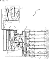
- Fig. 3 is a refrigerant circuit diagram illustrating the flows of the refrigerants in the cooling only operation mode of the air-conditioning apparatus 100.
- the cooling only operation mode will be described with respect to a case in which cooling loads are generated only in the use side heat exchanger 26a and the use side heat exchanger 26b in Fig. 3 .
- pipes indicated by thick lines indicate the pipes through which the heat source side refrigerant and the heat medium flow.
- solid-line arrows indicate the flow direction of the heat source side refrigerant and broken-line arrows indicate the flow direction of the heat medium.
- the first refrigerant flow switching device 11 is allowed to perform switching such that the heat source side refrigerant discharged from the compressor 10 flows into the heat source side heat exchanger 12.
- the pump 21a and the pump 21b are driven, the heat medium flow control device 25a and the heat medium flow control device 25b are opened, and the heat medium flow control device 25c and the heat medium flow control device 25d are fully closed such that the heat medium circulates between each of the heat exchanger 15a related to heat medium and the heat exchanger 15b related to heat medium, and each of the use side heat exchanger 26a and the use side heat exchanger 26b.
- a low temperature, low pressure refrigerant is compressed by the compressor 10 and is discharged as a high temperature, high pressure gas refrigerant therefrom.
- the high temperature, high pressure gas refrigerant discharged from the compressor 10 flows through the first refrigerant flow switching device 11 into the heat source side heat exchanger 12. Then, the refrigerant is condensed and liquefied into a high pressure liquid refrigerant while transferring heat to outdoor air in the heat source side heat exchanger 12.
- the high pressure liquid refrigerant which has flowed out of the heat source side heat exchanger 12 passes through the check valve 13a, flows out of the outdoor unit 1, passes through the refrigerant pipes 4, and flows into the heat medium relay unit 3.
- the high pressure liquid refrigerant which has flowed into the heat medium relay unit 3, passes through the opening and closing device 17a and is then divided into flows to the expansion device 16a and the expansion device 16b, in each of which the refrigerant is expanded into a low temperature, low pressure two-phase refrigerant.
- This two-phase refrigerant flows into each of the heat exchanger 15a related to heat medium and the heat exchanger 15b related to heat medium, functioning as evaporators, from the lower side of the drawing, removes heat from the heat medium circulating in the heat medium circuits B, cools the heat medium, and turns into a low temperature, low pressure gas refrigerant.
- the gas refrigerant which has flowed out of the upper side of the drawing of each of the heat exchanger 15a related to heat medium and the heat exchanger 15b related to heat medium, flows out of the heat medium relay unit 3 through the corresponding one of the second refrigerant flow switching device 18a and the second refrigerant flow switching device 18b, passes through the refrigerant pipe 4, and again flows into the outdoor unit 1.
- the refrigerant which has flowed into the outdoor unit 1 passes through the check valve 13d, the first refrigerant flow switching device 11, and the accumulator 19, and is again suctioned into the compressor 10.
- the opening degree of the expansion device 16a is controlled such that superheat (the degree of superheat) obtained as the difference between a temperature detected by the third temperature sensor 35a and that detected by the third temperature sensor 35b is constant.
- the opening degree of the expansion device 16b is controlled such that superheat obtained as the difference between a temperature detected by a third temperature sensor 35c and that detected by a third temperature sensor 35d is constant.
- the opening and closing device 17a is opened and the opening and closing device 17b is closed.
- the heat medium which has been pressurized by and flowed out of the pump 21a flows into the heat exchanger 15a related to heat medium from the upper side of the drawing, via the heat medium flow reversing device 20a. Then, the heat medium cooled by the heat source side refrigerant in the heat exchanger 15a related to heat medium flows out of the lower side of the drawing of the heat exchanger 15a related to heat medium, passes through the heat medium flow reversing device 20b, and reaches the second heat medium flow switching device 23a and the second heat medium flow switching device 23b.
- the heat medium which has been pressurized by and flowed out of the pump 21b flows into the heat exchanger 15b related to heat medium from the upper side of the drawing, via the heat medium flow reversing device 20c. Then, the heat medium cooled by the heat source side refrigerant in the heat exchanger 15b related to heat medium flows out from the lower side of the drawing of the heat exchanger 15b related to heat medium, passes through the heat medium flow reversing device 20d, and reaches the second heat medium flow switching device 23a and the second heat medium flow switching device 23b.
- the heat medium pressed out of the pump 21a and the heat medium pressed out of the pump 21b are merged in each of the second heat medium flow switching device 23a and the second heat medium flow switching device 23b into the corresponding one of the use side heat exchanger 26a and the use side heat exchanger 26b.
- the heat medium removes heat from the indoor air in each of the use side heat exchanger 26a and the use side heat exchanger 26b, and thus cools the indoor space 7.
- the use side heat exchanger 26a and the use side heat exchanger 26b each functions as a cooler, and are preferably configured so that the flow direction of the heat medium and the indoor air (second heat medium) are counter to each other in the use side heat exchanger 26a and the use side heat exchanger 26b.
- each of the heat medium flow control device 25a and the heat medium flow control device 25b controls a flow rate of the heat medium as necessary to cover an air conditioning load required in the indoor space such that the controlled flow rate of the heat medium flows into the corresponding one of the use side heat exchanger 26a and the use side heat exchanger 26b.
- the heat medium which has flowed out of each of the heat medium flow control device 25a and the heat medium flow control device 25b, is branched off in the first heat medium flow switching device 22a and the first heat medium flow switching device 22b respectively, back into the pump 21a and the pump 21b.
- the flow of the heat source side refrigerant and the flow of the heat medium can be counter to each other in the heat exchanger 15a related to heat medium and the heat exchanger 15b related to heat medium.
- the heat source side refrigerant flows from the lower side of the drawing toward the upper side of the drawing, whereas the heat medium flows from the upper side of the drawing toward the lower side of the drawing, so that the flow of the heat source side refrigerant and the flow of the heat medium are counter to each other. Passing the heat source side refrigerant and the heat medium in counterflow improves the heat transfer efficiency and COP.
- the heat medium is directed to flow from the second heat medium flow switching device 23 through the heat medium flow control device 25 to the first heat medium flow switching device 22. Furthermore, the difference between the temperature detected by the first temperature sensor 31a or that detected by the first temperature sensor 31b and the temperature detected by each of the second temperature sensors 34 is controlled such that the difference is held at a target value, so that the air conditioning load required in the indoor space 7 can be covered.
- a temperature at the outlet of each heat exchanger 15 related to heat medium either of the temperature detected by the first temperature sensor 31a or that detected by the first temperature sensor 31b may be used. Alternatively, the mean temperature of the two may be used.
- the opening degree of each of the first heat medium flow switching devices 22 and the corresponding second heat medium flow switching device 23 are set to a medium degree such that passages to both of the heat exchanger 15a related to heat medium and the heat exchanger 15b related to heat medium are established.
- the passage is closed by the corresponding heat medium flow control device 25 such that the heat medium does not flow into the corresponding use side heat exchanger 26.
- the heat medium flows into the use side heat exchanger 26a and the use side heat exchanger 26b because these use side heat exchangers each have a heat load.
- the use side heat exchanger 26c and the use side heat exchanger 26d have no heat load and the corresponding one of heat medium flow control devices 25c and 25d are fully closed.
- the heat medium flow control device 25c or the heat medium flow control device 25d may be opened such that the heat medium is circulated.
- Fig. 4 is a refrigerant circuit diagram illustrating the flows of the refrigerants in the heating only operation mode of the air-conditioning apparatus 100.
- the heating only operation mode will be described with respect to a case in which heating loads are generated only in the use side heat exchanger 26a and the use side heat exchanger 26b in Fig. 4 .
- pipes indicated by thick lines indicate the pipes through which the heat source side refrigerant and the heat medium flow.
- solid-line arrows indicate the flow direction of the heat source side refrigerant and broken-line arrows indicate the flow direction of the heat medium.
- the first refrigerant flow switching device 11 is switched such that the heat source side refrigerant discharged from the compressor 10 flows into the heat medium relay unit 3 without passing through the heat source side heat exchanger 12 in the outdoor unit 1.
- the pump 21a and the pump 21b are driven, the heat medium flow control device 25a and the heat medium flow control device 25b are opened, and the heat medium flow control device 25c and the heat medium flow control device 25d are fully closed such that the heat medium circulates between each of the heat exchanger 15a related to heat medium and the heat exchanger 15b related to heat medium, and each of the use side heat exchanger 26a and the use side heat exchanger 26b.
- a low temperature, low pressure refrigerant is compressed by the compressor 10 and is discharged as a high temperature, high pressure gas refrigerant therefrom.
- the high temperature, high pressure gas refrigerant discharged from the compressor 10 passes through the first refrigerant flow switching device 11, flows through the first connecting pipe 4a, passes through the check valve 13b, and flows out of the outdoor unit 1.
- the high temperature, high pressure gas refrigerant that has flowed out of the outdoor unit 1 passes through the refrigerant pipe 4 and flows into the heat medium relay unit 3.
- the high temperature, high pressure gas refrigerant which has flowed into the heat medium relay unit 3 is branched, passes through each of the second refrigerant flow switching device 18a and the second refrigerant flow switching device 18b, and flows into the corresponding one of the heat exchanger 15a related to heat medium and the heat exchanger 15b related to heat medium from the upper side of the drawing.
- the high temperature, high pressure gas refrigerant which has flowed into each of the heat exchanger 15a related to heat medium and the heat exchanger 15b related to heat medium from the upper side of the drawing is condensed and liquefied into a high pressure liquid refrigerant while transferring heat to the heat medium circulating in the heat medium circuits B.
- the liquid refrigerant which has flowed out of the lower side of the drawing of each of the heat exchanger 15a related to heat medium and the heat exchanger 15b related to heat medium are expanded into a low temperature low pressure, two-phase refrigerant in the corresponding one of the expansion device 16a and the expansion device 16b.
- This two-phase refrigerant passes through the opening and closing device 17b, flows out of the heat medium relay unit 3, passes through the refrigerant pipe 4, and again flows into the outdoor unit 1.
- the refrigerant which has flowed into the outdoor unit 1 flows through the second connecting pipe 4b, passes through the check valve 13c, and flows into the heat source side heat exchanger 12, functioning as an evaporator.
- the refrigerant which has flowed into the heat source side heat exchanger 12 removes heat from the outdoor air in the heat source side heat exchanger 12 and thus turns into a low temperature, low pressure gas refrigerant.
- the low temperature, low pressure gas refrigerant which has flowed out of the heat source side heat exchanger 12 passes through the first refrigerant flow switching device 11 and the accumulator 19 and is suctioned into the compressor 10 again.
- the opening degree of the expansion device 16a is controlled such that subcooling (degree of subcooling) obtained as the difference between a saturation temperature converted from a pressure detected by the pressure sensor 36 and a temperature detected by the third temperature sensor 35b is constant.
- the opening degree of the expansion device 16b is controlled such that subcooling obtained as the difference between the saturation temperature converted from the pressure detected by the pressure sensor 36 and a temperature detected by the third temperature sensor 35d.
- the opening and closing device 17a is closed and the opening and closing device 17b is opened. Note that when a temperature at the middle position of the heat exchangers 15 related to heat medium can be measured, the temperature at the middle position may be used instead of the pressure sensor 36. In this case, it is unnecessary to install the pressure sensor 36, thus the system can be established inexpensively.
- the heat medium which has been pressurized by and flowed out of the pump 21a flows into the heat exchanger 15a related to heat medium from the lower side of the drawing, via the heat medium flow reversing device 20a. Then, the heat medium heated by the heat source side refrigerant in the heat exchanger 15a related to heat medium flows out of the upper side of the drawing of the heat exchanger 15a related to heat medium, passes through the heat medium flow reversing device 20b, and reaches the second heat medium flow switching device 23a and the second heat medium flow switching device 23b.
- the heat medium which has been pressurized by and flowed out of the pump 21b flows into the heat exchanger 15b related to heat medium from the lower side of the drawing, via the heat medium flow reversing device 20c. Then, the heat medium heated by the heat source side refrigerant in the heat exchanger 15b related to heat medium flows out of the upper side of the drawing of the heat exchanger 15b related to heat medium, passes through the heat medium flow reversing device 20d, and reaches the second heat medium flow switching device 23a and the second heat medium flow switching device 23b.
- the heat medium pressed out of the pump 21a and the heat medium pressed out of the pump 21b are merged in each of the second heat medium flow switching device 23a and the second heat medium flow switching device 23b into the corresponding one of the use side heat exchanger 26a and the use side heat exchanger 26b.
- the heat medium transfers heat to the indoor air in each of the use side heat exchanger 26a and the use side heat exchanger 26b, and thus heats the indoor space 7.
- the use side heat exchanger 26a and the use side heat exchanger 26b each functions as a heater, and are preferably configured so that the flow direction of the heat medium and the indoor air (second heat medium) are counter to each other in the use side heat exchanger 26a and the use side heat exchanger 26b as is the case in which these use side heat exchangers each function as a cooler.
- each of the heat medium flow control device 25a and the heat medium flow control device 25b controls a flow rate of the heat medium as necessary to cover an air conditioning load required in the indoor space such that the controlled flow rate of the heat medium flows into the corresponding one of the use side heat exchanger 26a and the use side heat exchanger 26b.
- the heat medium which has flowed out of each of the heat medium flow control device 25a and the heat medium flow control device 25b, is branched off in the first heat medium flow switching device 22a and the first heat medium flow switching device 22b respectively, back into the pump 21a and the pump 21b.
- the flow of the heat source side refrigerant and the flow of the heat medium can be counter to each other in the heat exchanger 15a related to heat medium and the heat exchanger 15b related to heat medium.
- the heat source side refrigerant flows from the upper side of the drawing toward the lower side of the drawing, whereas the heat medium flows from the lower side of the drawing toward the upper side of the drawing, so that the flow of the heat source side refrigerant and the flow of the heat medium are counter to each other. Passing the heat source side refrigerant and the heat medium in counterflow improves the heat transfer efficiency and COP.
- the heat medium is directed to flow from the second heat medium flow switching device 23 through the heat medium flow control device 25 to the first heat medium flow switching device 22. Furthermore, the difference between the temperature detected by the first temperature sensor 31a or that detected by the first temperature sensor 31b and the temperature detected by each of the second temperature sensors 34 is controlled such that the difference is held at a target value, so that the air conditioning load required in the indoor space 7 can be covered.
- a temperature at the outlet of each heat exchanger 15 related to heat medium either of the temperature detected by the first temperature sensor 31a or that detected by the first temperature sensor 31b may be used. Alternatively, the mean temperature of the two may be used.
- the opening degree of each of the first heat medium flow switching devices 22 and the corresponding second heat medium flow switching device 23 are set to the medium degree such that passages to both of the heat exchanger 15a related to heat medium and the heat exchanger 15b related to heat medium are established.
- the use side heat exchanger 26a should essentially be controlled on the basis of the difference between a temperature at the inlet and that at the outlet thereof, since a temperature of the heat medium on the inlet side of the use side heat exchanger 26 is substantially the same as the temperature detected by the first temperature sensor 31b, the use of the first temperature sensor 31b can reduce the number of temperature sensors, so that the system can be established inexpensively.
- the passage is closed by the corresponding heat medium flow control device 25 such that the heat medium does not flow into the use side heat exchanger 26.
- the heat medium flows into the use side heat exchanger 26a and the use side heat exchanger 26b because these use side heat exchangers each have a heat load.
- the use side heat exchanger 26c and the use side heat exchanger 26d have no heat load and the corresponding one of heat medium flow control devices 25c and 25d are fully closed.
- the heat medium flow control device 25c or the heat medium flow control device 25d may be opened such that the heat medium is circulated.
- Fig. 5 is a refrigerant circuit diagram illustrating the flows of the refrigerants in the cooling main operation mode of the air-conditioning apparatus 100.
- the cooling main operation mode will be described with respect to a case in which a cooling load is generated in the use side heat exchanger 26a and a heating load is generated in the use side heat exchanger 26b in Fig. 5 .
- pipes indicated by thick lines correspond to the pipes through which the heat source side refrigerant and the heat medium circulate.
- solid-line arrows indicate the flow direction of the heat source side refrigerant and broken-line arrows indicate the flow direction of the heat medium.
- the first refrigerant flow switching device 11 is allowed to perform switching such that the heat source side refrigerant discharged from the compressor 10 flows into the heat source side heat exchanger 12.
- the pump 21a and the pump 21b are driven, the heat medium flow control device 25a and the heat medium flow control device 25b are opened, and the heat medium flow control device 25c and the heat medium flow control device 25d are fully closed such that the heat medium circulates between the heat exchanger 15a related to heat medium and the use side heat exchanger 26a, and between the heat exchanger 15b related to heat medium and the use side heat exchanger 26b.
- a low temperature, low pressure refrigerant is compressed by the compressor 10 and is discharged as a high temperature, high pressure gas refrigerant therefrom.
- the high temperature, high pressure gas refrigerant discharged from the compressor 10 flows through the first refrigerant flow switching device 11 into the heat source side heat exchanger 12.
- the refrigerant is condensed into a two-phase refrigerant in the heat source side heat exchanger 12 while transferring heat to the outside air.
- the two-phase refrigerant, which has flowed out of the heat source side heat exchanger 12 passes through the check valve 13a, flows out of the outdoor unit 1, passes through the refrigerant pipe 4, and flows into the heat medium relay unit 3.
- the two-phase refrigerant which has flowed into the heat medium relay unit 3, passes through the second refrigerant flow switching device 18b and flows into the heat exchanger 15b related to heat medium, functioning as a condenser, from the upper side of the drawing.
- the two-phase refrigerant that has flowed into the heat exchanger 15b related to heat medium from the upper side of the drawing is condensed and liquefied while transferring heat to the heat medium circulating in the heat medium circuits B, and turns into a liquid refrigerant.
- the liquid refrigerant which has flowed out of the lower side of the drawing of the heat exchanger 15b related to heat medium is expanded into a low pressure two-phase refrigerant by the expansion device 16b. This low pressure two-phase refrigerant flows through the expansion device 16a and into the heat exchanger 15a related to heat medium functioning as an evaporator from the lower side of the drawing.
- the low pressure two-phase refrigerant which has flowed into the heat exchanger 15a related to heat medium from the lower side of the drawing, removes heat from the heat medium circulating in the heat medium circuits B to cool the heat medium, and thus turns into a low pressure gas refrigerant.
- the gas refrigerant flows out of the upper side of the drawing of the heat exchanger 15a related to heat medium, passes through the second refrigerant flow switching device 18a, flows out of the heat medium relay unit 3, and flows into the outdoor unit 1 again through the refrigerant pipe 4.
- the heat source side refrigerant which has flowed into the outdoor unit 1, passes through the check valve 13d, the first refrigerant flow switching device 11 and the accumulator 19, and is then again suctioned into the compressor 10.
- the opening degree of the expansion device 16b is controlled such that superheat obtained as the difference between a temperature detected by the third temperature sensor 35a and that detected by the third temperature sensor 35b is constant.
- the expansion device 16a is fully opened, the opening and closing device 17a is closed, and the opening and closing device 17b is closed.
- the opening degree of the expansion device 16b may be controlled such that subcooling obtained as the difference between a value indicating a saturation temperature converted from a pressure detected by the pressure sensor 36 and a temperature detected by the third temperature sensor 35d is constant.
- the expansion device 16b may be fully opened and the expansion device 16a may control the superheat or the subcooling.
- the heat exchanger 15b related to heat medium transfers heating energy of the heat source side refrigerant to the heat medium, and the pump 21b allows the heated heat medium to flow through the pipes 5. Furthermore, in the cooling main operation mode, the heat exchanger 15a related to heat medium transfers cooling energy of the heat source side refrigerant to the heat medium, and the pump 21a allows the cooled heat medium to flow through the pipes 5.
- the heat medium which has been pressurized by and flowed out of the pump 21b flows into the heat exchanger 15b related to heat medium from the lower side of the drawing via the heat medium flow reversing device 20c. Then, the heat medium heated by the heat source side refrigerant in the heat exchanger 15b related to heat medium flows out of the upper side of the drawing of the heat exchanger 15b related to heat medium, passes through the heat medium flow reversing device 20d, and reaches the second heat medium flow switching device 23b.
- the heat medium which has been pressurized by and flowed out of the pump 21a flows into the heat exchanger 15a related to heat medium from the upper side of the drawing, via the heat medium flow reversing device 20a.
- the heat medium cooled by the heat source side refrigerant in the heat exchanger 15a related to heat medium flows out of the lower side of the drawing of the heat exchanger 15a related to heat medium, passes through the heat medium flow reversing device 20b, and reaches the second heat medium flow switching device 23a.
- the heat medium which has passed through the second heat medium flow switching device 23b flows into the use side heat exchanger 26b, and transfers heat to the indoor air, thereby heating the indoor space 7.
- the heat medium which has passed through the second heat medium flow switching device 23a flows into the use side heat exchanger 26a, and removes heat from the indoor air, thereby cooling the indoor space 7.
- each of the heat medium flow control device 25a and the heat medium flow control device 25b controls a flow rate of the heat medium as necessary to cover an air conditioning load required in the indoor space such that the controlled flow rate of the heat medium flows into the corresponding one of the use side heat exchanger 26a and the use side heat exchanger 26b.
- the heat medium which has passed through the use side heat exchanger 26b with a slight decrease of temperature, passes through the heat medium flow control device 25b and the first heat medium flow switching device 22b and is suctioned into the pump 21b again.
- the heat medium which has passed through the use side heat exchanger 26a with a slight increase of temperature, passes through the heat medium flow control device 25a and the first heat medium flow switching device 22a, and is again suctioned into the pump 21a.
- the use side heat exchanger 26a functions as a cooler and the use side heat exchanger 26b functions as a heater, and they are preferably configured so that the flow direction of the heat medium and the indoor air are counter to each other in the use side heat exchanger 26a and the use side heat exchanger 26b.
- the first heat medium flow switching devices 22 and the second heat medium flow switching devices 23 allow the warm heat medium and the cold heat medium to be introduced into the use side heat exchanger 26 having a heating load and the use side heat exchanger 26 having a cooling load, respectively, without mixing with each other.
- the heat medium is directed to flow from the second heat medium flow switching device 23 through the heat medium flow control device 25 to the first heat medium flow switching device 22.
- the difference between a temperature detected by the first temperature sensor 31b and that detected by each of the second temperature sensors 34 is controlled such that the difference is held at a target value, so that the air conditioning load required in the indoor space 7 for heating can be covered.
- the difference between a temperature detected by each of the second temperature sensors 34 and that detected by the first temperature sensor 31a is controlled such that the difference is held at a target value, so that the air conditioning load required in the indoor space 7 for cooling can be covered.
- the flow of the heat source side refrigerant and the flow of the heat medium can be counter to each other in each of the heat exchanger 15a related to heat medium functioning as a cooler and the heat exchanger 15b related to heat medium functioning as a heater. As illustrated in Fig.
- the heat source side refrigerant flows from the lower side of the drawing toward the upper side of the drawing, whereas the heat medium flows from the upper side of the drawing toward the lower side of the drawing, and in the heat exchanger 15b related to heat medium, the heat source side refrigerant flows from the upper side of the drawing toward the lower side of the drawing, whereas the heat medium flows from the lower side of the drawing toward the upper side of the drawing, so that the flow of the heat source side refrigerant and the flow of the heat medium are counter to each other. Passing the heat source side refrigerant and the heat medium in counterflow improves the heat transfer efficiency and COP.
- a plate heat exchanger is used as the heat exchanger 15a related to heat medium functioning as a cooler
- the evaporated gas refrigerant moves to the upper side of the heat exchanger by the buoyancy effect.
- the power of the compressor 10 can be reduced, and the refrigerant can appropriately be distributed.
- the cooled heat medium sinks to the lower side of the heat exchanger by the gravitational effect. As a result, the power of the pump 21 can be reduced, and the operation can be more efficient.
- a plate heat exchanger is used as the heat exchanger 15b related to heat medium functioning as a heater
- the heat source side refrigerant on the condensation side is passed from the upper side to the lower side as illustrated in the drawing
- the condensed liquid refrigerant moves to the lower side of the heat exchanger by the gravitational effect.
- the power of the compressor 10 can be reduced.
- a plate heat exchanger is used as the heat exchanger 15b related to heat medium
- the heated heat medium floats to the upper side of the heat exchanger by the buoyancy effect.
- the power of the pump 21 can be reduced, and the operation can be more efficient.
- the passage is closed by the corresponding heat medium flow control device 25 such that the heat medium does not flow into the use side heat exchanger 26.
- the heat medium flows into the use side heat exchanger 26a and the use side heat exchanger 26b because these use side heat exchangers each have a heat load.
- the use side heat exchanger 26c and the use side heat exchanger 26d have no heat load and the corresponding heat medium flow control devices 25c and 25d are totally closed.
- the heat medium flow control device 25c or the heat medium flow control device 25d may be opened such that the heat medium is circulated.
- Fig. 6 is a refrigerant circuit diagram illustrating the flows of the refrigerants in the heating main operation mode of the air-conditioning apparatus 100.
- the heating main operation mode will be described with respect to a case in which a heating load is generated in the use side heat exchanger 26a and a cooling load is generated in the use side heat exchanger 26b in Fig. 6 .
- pipes indicated by thick lines correspond to the pipes through which the heat source side refrigerant and the heat medium circulate.
- solid-line arrows indicate the flow direction of the heat source side refrigerant and broken-line arrows indicate the flow direction of the heat medium.
- the first refrigerant flow switching device 11 is allowed to perform switching such that the heat source side refrigerant discharged from the compressor 10 flows into the heat medium relay unit 3 without passing through the heat source side heat exchanger 12.
- the pump 21a and the pump 21b are driven, the heat medium flow control device 25a and the heat medium flow control device 25b are opened, and the heat medium flow control device 25c and the heat medium flow control device 25d are fully closed such that the heat medium circulates between the heat exchanger 15a related to heat medium and the use side heat exchanger 26b and also circulates between the heat exchanger 15a related to heat medium and the use side heat exchanger 26b.
- a low temperature, low pressure refrigerant is compressed by the compressor 10 and is discharged as a high temperature, high pressure gas refrigerant therefrom.
- the high temperature, high pressure gas refrigerant discharged from the compressor 10 passes through the first refrigerant flow switching device 11, flows through the first connecting pipe 4a, passes through the check valve 13b, and flows out of the outdoor unit 1.
- the high temperature, high pressure gas refrigerant that has flowed out of the outdoor unit 1 passes through the refrigerant pipe 4 and flows into the heat medium relay unit 3.
- the high temperature, high pressure gas refrigerant which has flowed into the heat medium relay unit 3, passes through the second refrigerant flow switching device 18b and flows into the heat exchanger 15b related to heat medium, functioning as a condenser, from the upper side of the drawing.
- the gas refrigerant which has flowed into the heat exchanger 15b related to heat medium from the upper side of the drawing is condensed and liquefied while transferring heat to the heat medium circulating in the heat medium circuits B, and turns into a liquid refrigerant.
- the liquid refrigerant which has flowed out of the lower side of the heat exchanger 15b related to heat medium is expanded into a low pressure two-phase refrigerant by the expansion device 16b. This low pressure two-phase refrigerant flows through the expansion device 16a and into the heat exchanger 15a related to heat medium functioning as an evaporator from the lower side of the drawing.
- the low pressure two-phase refrigerant which has flowed into the heat exchanger 15a related to heat medium from the lower side of the drawing removes heat from the heat medium circulating in the heat medium circuits B and is evaporated to cool the heat medium.
- This low pressure two-phase refrigerant flows out of the upper side of the drawing of the heat exchanger 15a related to heat medium, passes through the second refrigerant flow switching device 18a, flows out of the heat medium relay unit 3, and flows into the outdoor unit 1 again through the refrigerant pipe 4.
- the heat source side refrigerant which has flowed into the outdoor unit 1, flows through the check valve 13c into the heat source side heat exchanger 12, functioning as an evaporator.
- the refrigerant which has flowed into the heat source side heat exchanger 12, removes heat from the outdoor air in the heat source side heat exchanger 12, such that it turns into a low temperature, low pressure gas refrigerant.
- the low temperature, low pressure gas refrigerant which has flowed out of the heat source side heat exchanger 12 passes through the first refrigerant flow switching device 11 and the accumulator 19 and is suctioned into the compressor 10 again.
- the opening degree of the expansion device 16b is controlled such that subcooling obtained as the difference between a value indicating a saturation temperature converted from a pressure detected by the pressure sensor 36 and a temperature detected by the third temperature sensor 35b is constant.
- the expansion device 16a is fully opened, the opening and closing device 17a is closed, and the opening and closing device 17b is closed. Note that, the expansion device 16b may be fully opened and the expansion device 16a may control the subcooling.
- the heat exchanger 15b related to heat medium transfers heating energy of the heat source side refrigerant to the heat medium and the pump 21b allows the heated heat medium to flow through the pipes 5. Furthermore, in the heating main operation mode, the heat exchanger 15a related to heat medium transfers cooling energy of the heat source side refrigerant to the heat medium and the pump 21a allows the cooled heat medium to flow through the pipes 5.
- the heat medium which has been pressurized by and flowed out of the pump 21b flows into the heat exchanger 15b related to heat medium from the lower side of the drawing via the heat medium flow reversing device 20c. Then, the heat medium heated by the heat source side refrigerant in the heat exchanger 15b related to heat medium flows out of the upper side of the drawing of the heat exchanger 15b related to heat medium, passes through the heat medium flow reversing device 20d, and reaches the second heat medium flow switching device 23a.
- the heat medium which has been pressurized by and flowed out of the pump 21a flows into the heat exchanger 15a related to heat medium from the upper side of the drawing, via the heat medium flow reversing device 20a.
- the heat medium cooled by the heat source side refrigerant in the heat exchanger 15a related to heat medium flows out of the lower side of the drawing of the heat exchanger 15a related to heat medium, passes through the heat medium flow reversing device 20b, and reaches the second heat medium flow switching device 23b.
- the heat medium which has passed through the second heat medium flow switching device 23a flows into the use side heat exchanger 26a, and transfers heat to the indoor air, thereby heating the indoor space 7.
- the heat medium which has passed through the second heat medium flow switching device 23b flows into the use side heat exchanger 26b, and removes heat from the indoor air, thereby cooling the indoor space 7.
- each of the heat medium flow control device 25a and the heat medium flow control device 25b controls a flow rate of the heat medium as necessary to cover an air conditioning load required in the indoor space such that the controlled flow rate of the heat medium flows into the corresponding one of the use side heat exchanger 26a and the use side heat exchanger 26b.
- the heat medium which has passed through the use side heat exchanger 26a with a slight decrease of temperature, passes through the heat medium flow control device 25a and the first heat medium flow switching device 22a, and is again suctioned into the pump 21b.
- the heat medium which has passed through the use side heat exchanger 26b with a slight increase of temperature, passes through the heat medium flow control device 25b and the first heat medium flow switching device 22b, and is again suctioned into the pump 21a.
- the use side heat exchanger 26a functions as a heater and the use side heat exchanger 26b functions as a cooler, and they are preferably configured so that the flow directions of the heat medium and the indoor air are counter to each other in the use side heat exchanger 26a and the use side heat exchanger 26b.
- the first heat medium flow switching devices 22 and the second heat medium flow switching devices 23 allow the warm heat medium and the cold heat medium to be introduced into the use side heat exchanger 26 having a heating load and the use side heat exchanger 26 having a cooling load, respectively, without mixing with each other.
- the heat medium is directed to flow from the second heat medium flow switching device 23 through the heat medium flow control device 25 to the first heat medium flow switching device 22.
- the difference between a temperature detected by the first temperature sensor 31b and that detected by each of the second temperature sensors 34 is controlled such that the difference is held at a target value, so that the air conditioning load required in the indoor space 7 for heating can be covered.
- the difference between a temperature detected by each of the second temperature sensors 34 and that detected by the first temperature sensor 31a is controlled such that the difference is held at a target value, so that the air conditioning load required in the indoor space 7 for cooling can be covered.
- the flow of the heat source side refrigerant and the flow of the heat medium can be counter to each other in each of the heat exchanger 15a related to heat medium functioning as a cooler and the heat exchanger 15b related to heat medium functioning as a heater. As illustrated in Fig.
- the heat source side refrigerant flows from the lower side of the drawing toward the upper side of the drawing, whereas the heat medium flows from the upper side of the drawing toward the lower side of the drawing, and in the heat exchanger 15b related to heat medium, the heat source side refrigerant flows from the upper side of the drawing toward the lower side of the drawing, whereas the heat medium flows from the lower side of the drawing toward the upper side of the drawing, so that the flow of the heat source side refrigerant and the flow of the heat medium are counter to each other. Passing the heat source side refrigerant and the heat medium in counterflow improves the heat transfer efficiency and COP.
- a plate heat exchanger is used as the heat exchanger 15a related to heat medium functioning as a cooler
- the evaporated gas refrigerant moves to the upper side of the heat exchanger by the buoyancy effect.
- the power of the compressor 10 can be reduced, and the refrigerant can appropriately be distributed.
- the cooled heat medium sinks to the lower side of the heat exchanger by the gravitational effect. As a result, the power of the pump 21 can be reduced, and the operation can be more efficient.
- the passage is closed by the corresponding heat medium flow control device 25 such that the heat medium does not flow into the use side heat exchanger 26.
- the heat medium flows into the use side heat exchanger 26a and the use side heat exchanger 26b because these use side heat exchangers each have a heat load.
- the use side heat exchanger 26c and the use side heat exchanger 26d have no heat load and the corresponding one of heat medium flow control devices 25c and 25d are fully closed.
- the heat medium flow control device 25c or the heat medium flow control device 25d may be opened such that the heat medium is circulated.
- Figs. 13 and 14 each illustrate the configuration of the heat medium flow reversing device 20 specifically, and illustrate a part of the heat medium relay unit illustrated in Fig. 2 in enlarged view.
- the specific configuration of the heat medium flow reversing device 20 will be described with reference to Figs. 13 and 14.
- Figs. 13 and 14 each illustrate the connecting part between the heat exchanger 15 related to heat medium, and the heat medium flow reversing device 20 connected to the heat exchanger 15 related to heat medium in enlarged view.
- the heat medium flow reversing devices 20a to 20d may be collectively referred to as heat medium flow reversing device 20.
- solid-line arrows indicate the flow direction of the heat source side refrigerant and broken-line arrows indicate the flow direction of the heat medium.
- the heat medium flow reversing device 20 is configured so that by rotating a cylindrical rotary tube 42, whose inside is hollowed, by a motor 41 such as a stepping motor, the position of a hole 43 having, for example, an elliptical or circular shape provided in the side of the rotary tube 42 is varied in the circumferential direction, thereby allowing the heat medium to flow between a connection port a connected to an end of the rotary tube 42, and a connection port b or connection port c each connected to the side part of the rotary tube 42.
- a motor 41 such as a stepping motor
- Fig. 13 illustrates a case where the heat exchanger 15a related to heat medium cools the heat medium (the cooling only operation mode, the cooling main operation mode, or the heating main operation mode), the operation is the same also for the heat exchanger 15b related to heat medium.
- FIG. 14 illustrates a case where the heat exchanger 15a related to heat medium heats the heat medium (the heating only operation mode), the operation is the same also for the heat exchanger 15b related to heat medium.
- the heat medium sent from the pump 21a flows into the heat medium flow reversing device 20a from the end a of the heat medium flow reversing device 20a.
- the heat medium which has flowed from the end a flows into the inside of the rotary tube 42 of the heat medium flow reversing device 20a, flows in the inside of the rotary tube 42, and flows out of the hole 43 provided in the side face of the rotary tube 42.
- the hole 43 of the heat medium flow reversing device 20a communicates with the connection port c connected to the side part of the rotary tube 42, and the heat medium which has flowed out of the hole 43 exits from the connection port c connected to the side part of the rotary tube 42.
- the heat medium flows into the heat exchanger 15a related to heat medium from the upper part of the drawing, flows out of the lower part of the drawing of the heat exchanger 15a related to heat medium
- the heat medium flows into the heat medium flow reversing device 20b from the connection port b connected to the side part of the rotary tube 42 of the heat medium flow reversing device 20b.
- the hole 43 is located at the connection port b in the heat medium flow reversing device 20b.
- the heat medium flows into the inside of the rotary tube 42 from the hole 43 provided in the side face of the rotary tube 42, flows inside the rotary tube 42, and flows out of the end a of the rotary tube 42.
- the refrigerant flows from the lower part to the upper part of the drawing, and the refrigerant and the heat medium are in counterflow.
- the heat medium sent from the pump 21a flows into the heat medium flow reversing device 20a from the end a of the heat medium flow reversing device 20a.
- the heat medium which has flowed from the end a flows into the inside of the rotary tube 42 of the heat medium flow reversing device 20a, flows in the inside of the rotary tube 42, and flows out of the hole 43 provided in the side face of the rotary tube 42.
- the hole 43 of the heat medium flow reversing device 20a communicates with the connection port c connected to the side part of the rotary tube 42, and the heat medium which has flowed out of the hole 43 exits from the connection port c connected to the side part of the rotary tube 42.
- the heat medium flows into the heat exchanger 15a related to heat medium from the lower part of the drawing, flows out of the upper part of the drawing of the heat exchanger 15a related to heat medium, and via a joint 44(a), the heat medium flows into the heat medium flow reversing device 20b from the connection port c connected to the side part of the rotary tube 42 of the heat medium flow reversing device 20b.
- the hole 43 is located at the connection port c in the heat medium flow reversing device 20b.
- the heat medium flows into the inside of the rotary tube 42 from the hole 43 provided in the side face of the rotary tube 42, flows inside the rotary tube 42, and flows out of the end a of the rotary tube 42.
- the refrigerant flows from the upper part to the lower part of the drawing, and the refrigerant and the heat medium are in counterflow.
- the heat medium flow reversing device is configured such that the heat medium flows out of an end of the rotary tube 42 of one heat medium flow reversing device 20, and flows out of the other end of the rotary tube 42 of the other heat medium flow reversing device 20.
- the heat medium flow reversing device 20a on the inlet side the heat medium flows out from the inside of the rotary tube 42 to the side face of the rotary tube 42
- the heat medium flow reversing device 20b on the outlet side the heat medium flows out from the side face of the rotary tube 42 to the inside of the rotary tube 42.
- Figs. 13 and 14 illustrate that the motor 41 and the rotary tube 42 are arranged horizontally in each of the heat medium flow reversing device 20a and the heat medium flow reversing device 20b, but the arrangement is not limited to this.
- the motor 41 and the rotary tube 42 may be installed vertically.
- the joint 44(a) and the joint 44(b) each may be a joint including a three-way passage such as a T-joint.
- the joint 44(a) and the joint 44(b) may not necessarily be provided, and a machining method such as boring a hole in the side face of a pipe, and inserting and securing another pipe in place may alternatively employed.
- the arrangement is not limited to this case.
- the configuration may be such that a plurality of heat medium flow reversing devices 20 are installed, which are divided into two sets of heat medium flow reversing devices 20 that perform the same operation within each single set.
- Fig. 7 is a schematic circuit diagram illustrating another exemplary circuit configuration of the air-conditioning apparatus 100 according to Embodiment. While Figs. 2 to 6 describe the example in which the heat medium flow reversing devices 20 each include a three-way valve and can switch the heat medium passage in three ways, Fig. 7 illustrates an example in which the heat medium flow reversing devices 20 each include an on-off valve such as a two-way valve, and switching operations of the heat medium passage in two ways are combined. Otherwise, there is no difference in configuration.
- each of the heat medium flow reversing devices 20 may include two on-off valves, thereby enabling switching of the heat medium passage.
- the heat medium flow reversing device 20a includes an on-off valve 20a(1) and an on-off valve 20a(2)
- the heat medium flow reversing device 20b includes an on-off valve 20b(1) and an on-off valve 20b(2)
- the heat medium flow reversing device 20c includes an on-off valve 20c(1) and an on-off valve 20c(2)
- the heat medium flow reversing device 20d includes an on-off valve 20d(1) and an on-off valve 20d(2).
- any refrigerant can improve the efficiency.
- the heat source side refrigerant for example, a single refrigerant such as R22, R134a, or R32, a near-azeotropic refrigerant mixture such as R410A or R404A, a refrigerant such as tetrafluoropropene such as HFO1234yf or HFO1234ze including a double bond in its chemical formula and considered to have a relatively low global warming potential, or a refrigerant that turns into a supercritical state such as CO2 or a natural refrigerant such as propane can be used.
- Fig. 8 is a p-h diagram illustrating the operational state in a case where a zeotropic refrigerant mixture is used as a heat source side refrigerant.
- a low temperature, low pressure gas refrigerant suctioned into the compressor 10 (Point A) is compressed into a high temperature, high pressure gas refrigerant (Point B).
- This high temperature, high pressure gas refrigerant is discharged from the compressor 10, and condensed in a heat exchanger operating as a condenser (the heat source side heat exchanger 12 or the heat exchanger 15a related to heat medium and/or the heat exchanger 15b related to heat medium) and turns into a high temperature, high pressure liquid refrigerant (Point C).
- This high temperature, high pressure liquid refrigerant is expanded in the expansion device 16a and/or the expansion device 16b and turns into a low temperature, low pressure two-phase refrigerant (Point D).
- the low temperature, low pressure two-phase refrigerant is evaporated in a heat exchanger operating as an evaporator (the heat source side heat exchanger 12 or the heat exchanger 15a related to heat medium and/or the heat exchanger 15b related to heat medium) and turns into a low temperature, low pressure gas refrigerant (Point A). Then, the refrigerant is suctioned into the compressor 10 again.
- Fig. 9 is a diagram for describing the operation in the case of using the heat exchanger 15a related to heat medium and/or the heat exchanger 15b related to heat medium as a condenser.
- Fig. 10 is a diagram for explaining the operation in the case of using the heat exchanger 15a related to heat medium and/or the heat exchanger 15b related to heat medium as an evaporator.
- the horizontal axis and the vertical axis represent the positions of the heat source side refrigerant and heat medium inside the condenser, and the temperatures of the heat source side refrigerant and heat medium, respectively.
- the horizontal axis and the vertical axis represent the positions of the heat source side refrigerant and heat medium inside the evaporator, and the temperatures of the heat source side refrigerant and heat medium, respectively.
- the heat source side refrigerant flows into the refrigerant side passage of the condenser in a gas state, drops in temperature by transferring heat to the heat medium on the outlet side of the heat medium passage of the condenser, and turns into a two-phase state.
- the heat source side refrigerant in the two-phase state transfers heat to the heat medium, the ratio of liquid refrigerant increases, and its temperature drops in accordance with the temperature difference between the saturated gas refrigerant temperature and the saturated liquid refrigerant temperature.
- the heat source side refrigerant turns into a liquid state and the refrigerant further drops in temperature by transferring heat to the heat medium on the inlet side of the heat medium passage of the condenser. Meanwhile, the temperature of the heat medium rises from the inlet side toward the outlet side, because the heat source side refrigerant and the heat medium flow in counterflow (in opposing directions) in the heat exchanger 15 related to heat medium.
- the heat source side refrigerant flows into the refrigerant side passage of the evaporator in a two-phase state, undergoes an increase in the ratio of gas refrigerant while removing heat from the heat medium on the outlet side of the heat medium passage of the evaporator, and rises in temperature in accordance with the temperature difference between the saturated gas refrigerant temperature and the saturated liquid refrigerant temperature.
- the heat source side refrigerant turns into a gas state by removing heat from the heat medium on the inlet side of the heat medium passage of the evaporator. Meanwhile, the temperature of the heat medium drops from the inlet side toward the outlet side, because the heat source side refrigerant and the heat medium flow in counterflow (in opposing directions) in the heat exchanger 15 related to heat medium.
- the temperature of the refrigerant rises by a temperature equivalent to the temperature difference between the saturated gas refrigerant temperature and the saturated liquid refrigerant temperature at the same pressure, along the line indicated by an alternate long and short dash line in Fig. 10 .
- the amount of this ideal temperature rise is represented by ⁇ T1.
- the temperature rise of the refrigerant from the inlet to the outlet of the evaporator becomes smaller than the temperature rise indicated by the alternate long and short dash lines in Fig. 10 , as indicated by a solid line.
- the amount of this temperature drop due to the pressure loss of the refrigerant is represented by ⁇ T2.
- Fig. 11 is a diagram showing temperature gradients (vertical axis) on the condenser side and on the evaporator side in a case where the mixing ratio (mass%) of R32 is varied in a refrigerant mixture of R32 and HFO1234yf (horizontal axis).
- the solid line and the alternate long and short dash line shown in Fig. 11 indicate the temperature gradient on the evaporator side and the temperature gradient on the condenser side, respectively.
- the region in which the ratio of R32 ranges from 2 mass% to 50 mass% is the region in which the temperature gradient is largest, and the temperature gradient on the evaporation side ranges from approximately 2.8 to 9.5 (K).
- the ratio of the refrigerant falls within this region, because the temperature gradient is large, Expression (1) holds even in the presence of a somewhat large temperature drop due to pressure loss, and the heat exchanger can be effectively used.
- FIG. 12 is a flowchart showing the flow of control process of the heat medium flow reversing device 20.
- the activation procedure in a case in which the compressor 10 is in a stopped state is as shown in the flowchart of Fig. 12 .
- activation of the compressor 10 is started when an activation command is issued (ST1).
- the unshown controller switches the heat medium flow reversing device 20 to the set position for the operation mode currently set (cooling only operation mode, heating only operation mode, or cooling and heating mixed operation mode (cooling main operation mode or heating main operation mode)) (ST2).
- the pump 21 is activated (ST3).
- the compressor 10 is activated (ST4).
- the activation process of the compressor 10 is performed through the above-mentioned procedure, and the activation process is ended (ST5).
- the passage for the pump 21 is reliably secured, and stable operation can be achieved.
- the pump 21 and the compressor 10 are stopped without changing the heat medium flow reversing device 20 from the position during operation. Then, when operation is resumed, the pump 21 and the compressor 10 may be activated in accordance with the flowchart shown in Fig. 12 . When operation is resumed, operation is performed again in the same state as the previous operational state in many cases. Accordingly, by ensuring that the position of the heat medium flow reversing device 20 when operation stops does not change from the position during operation, the activation time can be further made quicker and stable operation can be achieved more quickly.
- the direction of the heat medium flow reversing device 20 corresponding to one of the pumps 21 switches, and the flow direction of the heat medium within the heat exchanger 15 related to heat medium reverses. Consequently, a state in which the flow rate becomes zero occurs instantaneously during the switching, and accordingly, it is preferable to switch the heat medium flow reversing device 20 after reducing the flow rate of the heat medium passing through corresponding pump 21 in advance. In this way, an abrupt change in flow rate can be prevented, and the operation mode can be switched in a stable manner.
- the flow rate may be reduced by reducing the frequency.
- the voltage applied to the pump 21 may be reduced by a method such as switching the resistance, or a valve that can vary the opening area of the passage may be provided on the suction side or discharge side of the pump so that the flow rate to the pump 21 may be reduced by reducing the passage area.
- the air-conditioning apparatus 100 has several operation modes. In these operation modes, the heat source side refrigerant flows through the refrigerant pipes 4 connecting the outdoor unit 1 and the heat medium relay unit 3.
- the heat medium such as water or antifreeze, flows through the pipes 5 connecting the heat medium relay unit 3 and the indoor units 2.
- the corresponding first heat medium flow switching devices 22 and the corresponding second heat medium flow switching devices 23 are controlled so as to have a medium opening degree, such that the heat medium flows into both of the heat exchanger 15a related to heat medium and the heat exchanger 15b related to heat medium. Consequently, since both of the heat exchanger 15a related to heat medium and the heat exchanger 15b related to heat medium can be used for the heating operation or the cooling operation, the heat transfer area is increased, so that the heating operation or the cooling operation can efficiently be performed.
- the first heat medium flow switching device 22 and the second heat medium flow switching device 23 corresponding to the use side heat exchanger 26 which performs the heating operation are switched to the passage connected to the heat exchanger 15b related to heat medium for heating, and the first heat medium flow switching device 22 and the second heat medium flow switching device 23 corresponding to the use side heat exchanger 26 which performs the cooling operation are switched to the passage connected to the heat exchanger 15a related to heat medium for cooling, so that the heating operation or cooling operation can be freely performed in each indoor unit 2.
- each of the first heat medium flow switching devices 22 and the second heat medium flow switching devices 23 described in Embodiment may be any component which can switch passages, for example, a three-way valve capable of switching between flow directions in a three-way passage, or two two-way valves, such as on-off valves opening or closing a two-way passage used in combination.
- components such as a stepping-motor-driven mixing valve capable of changing flow rates of three passages or electronic expansion valves capable of changing flow rates of two passages used in combination may be used as each of the first heat medium flow switching devices 22 and the second heat medium flow switching devices 23. In this case, water hammer caused when a passage is suddenly opened or closed can be prevented.
- each of the heat medium flow control devices 25 may be a control valve having a three-way passage and the valve may be disposed with a bypass pipe that bypasses the corresponding use side heat exchanger 26.
- each of the heat medium flow control devices 25 may be a two-way valve or a three-way valve whose one end is closed as long as it is capable of controlling a flow rate in a passage in a stepping-motor-driven manner.
- a component such as an on-off valve, which is capable of opening or closing a two-way passage, may be used while ON and OFF operations are repeated to control an average flow rate.
- the first heat medium flow switching device 22 can also function as the heat medium flow control device 25, and thus there is no need to install the heat medium flow control device 25 separately. That is, as long as flow switching and flow control can be performed simultaneously, the first heat medium flow switching device 22 and the heat medium flow control device 25 may be the same.
- heat medium flow reversing device 20 other than a device such as a three-way valve that can switch a three-way passages, two devices such as on-off valves illustrated in Fig. 7 that open and close a two-way passage may be combined, and any devices that can switch the passage may be used.
- components such as a stepping-motor-driven mixing valve capable of changing flow rates of three-way passages or electronic expansion valves capable of changing flow rates of two-way passages used in combination may be used.
- each second refrigerant flow switching device 18 is described as a four-way valve, the device is not limited to this type.
- a plurality of two-way or three-way flow switching valves may be used such that the refrigerant flows in the same way.
- the apparatus is not limited to the case. Even in an apparatus that is configured by a single heat exchanger 15 related to heat medium and a single expansion device 16 that are connected to a plurality of parallel use side heat exchangers 26 and heat medium flow control devices 25, and even in an apparatus that is only capable of carrying out a cooling operation or a heating operation, the same advantages can be obtained.
- each heat medium flow control device 25 may be disposed in the indoor unit 2.
- the heat medium relay unit 3 may be separated from the indoor unit 2.
- a heat exchanger related to heat medium configured as a double-pipe heat exchanger, a micro-channel heat exchanger, or the like may be used.
- the heat medium for example, brine (antifreeze), water, a mixed solution of brine and water, or a mixed solution of water and an additive with high anticorrosive effect can be used.
- brine antifreeze
- water a mixed solution of brine and water
- the air-conditioning apparatus 100 therefore, even if the heat medium leaks through the indoor unit 2 into the indoor space 7, the safety of the heat medium used is high. Accordingly, it contributes to safety improvement.
- each of the heat source side heat exchanger 12 and the use side heat exchangers 26 is provided with an air-sending device and in many cases, air sending facilitates condensation or evaporation.
- the structure is not limited to this case.
- a panel heater and the like, taking advantage of radiation can be used as the use side heat exchanger 26 and a water-cooled heat exchanger which transfers heat using water or antifreeze can be used as the heat source side heat exchanger 12.
- any type of heat exchanger can be used as each of the heat source side heat exchanger 12 and the use side heat exchanger 26.
- the heating efficiency in the heat source side heat exchanger 12 can be improved also in the configuration in which the heat source side heat exchanger 12 is a water-cooled heat exchanger, and the passage on the refrigerant side reverses in the heat source side heat exchanger 12.
- the heat medium flow reversing device 20a and the heat medium flow reversing device 20b may be connected to the heat source side heat exchanger 12 in the same manner as the heat exchanger 15 related to heat medium.
- the air-conditioning apparatus may be of a direct expansion type which circulates refrigerant between the heat source side heat exchanger 12 and the use side heat exchangers 26a to 26d, and the same advantages can be obtained.
- the air-conditioning apparatus may be of a direct expansion type which circulates refrigerant between the heat source side heat exchanger 12 and the use side heat exchangers 26a to 26d, and the same advantages can be obtained.
- any number thereof can be connected.
- each of the number of pumps 21a and 21b is not limited to one. A plurality of pumps having a small capacity may be arranged in parallel.
- the heat medium flow reversing devices 20a to 20d are installed in the heat medium relay unit 3 that is a separate component from the outdoor unit 1
- the arrangement is not limited to this case.
- energy saving performance deteriorates slightly owing to an increase in conveyance power of water
- the heat exchanger 15a related to heat medium, the heat exchanger 15b related to heat medium, and the heat medium flow reversing devices 20a to 20d may be installed in the outdoor unit 1.
- the air-conditioning apparatus 100 improves safety by not allowing the heat source side refrigerant to circulate to each indoor unit 2 or the vicinity of the indoor unit 2, and by not allowing an the heat medium that has leaked from the connections between the pipes 5 and individual actuators (driving parts such as the pump 21, the first heat medium flow switching device 22, the second heat medium flow switching device 23, the expansion device 16, and the second refrigerant flow switching device 18) to flow out to the air-conditioned space.
- the air-conditioning apparatus 100 can contribute to improvement of energy efficiency.
- the air-conditioning apparatus 100 can save energy because the pipes 5 can be made shorter.
- the air-conditioning apparatus 100 includes a reduced number of pipes (the refrigerant pipes 4, the pipes 5) connecting the outdoor unit 1 and the heat medium relay unit 3 or connecting the heat medium relay unit 3 and the indoor unit 2 to make the installation easier.
Landscapes
- Engineering & Computer Science (AREA)
- Mechanical Engineering (AREA)
- General Engineering & Computer Science (AREA)
- Physics & Mathematics (AREA)
- Thermal Sciences (AREA)
- Chemical & Material Sciences (AREA)
- Combustion & Propulsion (AREA)
- Other Air-Conditioning Systems (AREA)
- Air Conditioning Control Device (AREA)
- Heat-Exchange Devices With Radiators And Conduit Assemblies (AREA)
Claims (20)
- Appareil de climatisation (100) qui a :un circuit de réfrigérant (A) dans lequel un compresseur (10), un premier échangeur de chaleur (12), un premier dispositif d'expansion (16) et un passage du côté du réfrigérant d'un deuxième échangeur de chaleur (15) sont raccordés par des tuyaux de réfrigérant (4) pour faire circuler un réfrigérant du côté de la source de chaleur ; etun circuit de fluide caloporteur (B) dans lequel une pompe (21) et un passage du côté du fluide caloporteur du deuxième échangeur de chaleur (15) sont raccordés par des tuyaux de fluide caloporteur pour faire circuler un fluide caloporteur,le deuxième échangeur de chaleur (15) échangeant la chaleur entre le réfrigérant du côté de la source de chaleur et le fluide caloporteur, l'appareil comprenant :un dispositif d'inversion d'écoulement de fluide caloporteur (20) prévu dans le circuit de fluide caloporteur (B) pour commuter une direction d'écoulement du fluide caloporteur dans le passage du côté du fluide caloporteur du deuxième échangeur de chaleur (15),dans lequel le dispositif d'inversion d'écoulement de fluide caloporteur (20) est formé par une pluralité de valves à trois voies qui sont chacune prévues avec un moteur (41), un tube rotatif (42) ayant une forme cylindrique, et un trou (43) qui est prévu dans une face latérale du tube rotatif (42) et qui permet au fluide caloporteur de s'écouler entre un intérieur et un extérieur du tube rotatif (42),la pluralité de valves à trois voies pouvant modifier une position du trou (43) dans la face latérale du tube rotatif (42) dans une direction circonférentielle en faisant tourner le tube rotatif (42) par une action du moteur (41),la pluralité de valves à trois voies étant divisée en deux ensembles ; etle fluide caloporteur qui circule à travers le circuit de fluide caloporteur (B) s'écoule à partir d'une extrémité d'un tube rotatif (42) dans un ensemble de valves à trois voies, et s'écoule hors d'une extrémité d'un tube rotatif (42) dans un autre ensemble de valves à trois voies, les deux dans un cas dans lequel le fluide caloporteur est refroidi dans le deuxième échangeur de chaleur (15) et un cas dans lequel le fluide caloporteur est chauffé dans le deuxième échangeur de chaleur (15).
- Appareil de climatisation (100) selon la revendication 1, dans lequel le dispositif d'inversion de fluide caloporteur (20) inverse la direction d'écoulement du fluide caloporteur dans le deuxième échangeur de chaleur (15), et peut commuter une relation d'une direction d'écoulement du réfrigérant du côté de la source de chaleur et la direction d'écoulement du fluide caloporteur entre un écoulement parallèle et un écoulement à contre-courant dans le deuxième échangeur de chaleur (15).
- Appareil de climatisation (100) selon la revendication 2, dans lequel le dispositif d'inversion d'écoulement de fluide caloporteur (20) peut commuter la direction d'écoulement du fluide caloporteur dans le deuxième échangeur de chaleur (15) selon la direction d'écoulement du réfrigérant du côté de la source de chaleur.
- Appareil de climatisation (100) selon la revendication 3, dans lequel, dans un cas dans lequel un échangeur de chaleur à plaques est utilisé en tant que deuxième échangeur de chaleur (15), un passage est formé, dans lequel :lorsque le deuxième échangeur de chaleur (15) chauffe le fluide caloporteur, le réfrigérant du côté de la source de chaleur s'écoule depuis un côté supérieur vers un côté inférieur, et le fluide caloporteur s'écoule depuis le côté inférieur vers le côté supérieur, etlorsque le deuxième échangeur de chaleur (15) refroidit le fluide caloporteur, le réfrigérant du côté de la source de chaleur s'écoule depuis le côté inférieur vers le côté supérieur, et le fluide caloporteur s'écoule depuis le côté supérieur vers le côté inférieur.
- Appareil de climatisation (100) selon l'une quelconque des revendications 1 à 4, dans lequel :
le dispositif d'inversion d'écoulement de fluide caloporteur (20) est configuré par :un premier dispositif d'inversion d'écoulement de fluide caloporteur (20) qui est raccordé par des tuyaux à une extrémité du deuxième échangeur de chaleur (15) et à une autre extrémité du deuxième échangeur de chaleur (15) via un premier orifice de raccordement, etun second dispositif d'inversion d'écoulement de fluide caloporteur (20) qui est raccordé par des tuyaux à l'autre extrémité du deuxième échangeur de chaleur (15), et à la une extrémité du deuxième échangeur de chaleur (15) via un second orifice de raccordement ;le premier orifice de raccordement est disposé dans un passage entre l'autre extrémité du deuxième échangeur de chaleur (15) et le second dispositif d'inversion d'écoulement de fluide caloporteur (20) ; etle second orifice de raccordement est disposé dans un passage entre la une extrémité du deuxième échangeur de chaleur (15) et le premier dispositif d'inversion d'écoulement de fluide caloporteur (20). - Appareil de climatisation (100) selon l'une quelconque des revendications 1 à 5, comprenant :
une pluralité de deuxièmes échangeurs de chaleur (15) et une pluralité de pompes, dans lequel :
le circuit de fluide caloporteur (B) comprend :un troisième échangeur de chaleur (26) qui fournit l'énergie de refroidissement ou l'énergie de chauffage à un espace climatisé, etun dispositif de commutation d'écoulement de fluide caloporteur (22, 23) qui sélectionne le fluide caloporteur qui a été refroidi ou le fluide caloporteur qui a été chauffé, et peut faire passer le fluide caloporteur sélectionné dans le troisième échangeur de chaleur (26) ; etle fluide caloporteur envoyé à partir de la pompe est circulé vers le troisième échangeur de chaleur (26) via le dispositif de commutation d'écoulement de fluide caloporteur (22, 23). - Appareil de climatisation (100) selon la revendication 6, comprenant :une fonction d'opération mixte de refroidissement et de chauffage qui chauffe une partie du fluide caloporteur et refroidit le fluide caloporteur résiduel ;une fonction uniquement d'opération de chauffage qui chauffe uniquement le fluide caloporteur ; etune fonction uniquement d'opération de refroidissement qui refroidit uniquement le fluide caloporteur,dans lequel dans la fonction d'opération mixte de refroidissement et de chauffage, une direction d'écoulement du fluide caloporteur dans le deuxième échangeur de chaleur (15) pour chauffer et une direction d'écoulement du fluide caloporteur dans le deuxième échangeur de chaleur (15) pour refroidir, sont opposées l'une par rapport à l'autre, etdans la fonction uniquement d'opération de chauffage et la fonction uniquement d'opération de refroidissement, les directions d'écoulement du fluide caloporteur dans une pluralité de deuxièmes échangeurs de chaleur (15) sont les mêmes.
- Appareil de climatisation (100) selon la revendication 7, dans lequel dans l'une quelconque parmi la fonction uniquement d'opération de refroidissement, la fonction uniquement d'opération de chauffage, et la fonction d'opération mixte de refroidissement et de chauffage, dans chaque troisième échangeur de chaleur (26),
une direction d'écoulement du fluide caloporteur et une direction d'écoulement d'un second fluide caloporteur qui s'écoule autour du troisième échangeur de chaleur (26) sont à contre-courant. - Appareil de climatisation (100) selon l'une quelconque des revendications 6 à 8, dans lequel :le compresseur (10) et le premier échangeur de chaleur (12) sont logés dans une unité extérieure ;le deuxième échangeur de chaleur (15), la pompe (21) et le dispositif d'inversion de fluide caloporteur (20) sont logés dans une unité de relais de fluide caloporteur ;le troisième échangeur de chaleur (26) est logé dans une unité intérieure ; etl'unité extérieure, l'unité de relais de fluide caloporteur et l'unité intérieure sont chacune formées comme un corps séparé.
- Appareil de climatisation (100) selon la revendication 9, dans lequel l'unité extérieure est raccordée à l'unité de relais de fluide caloporteur par deux tuyaux et l'unité de relais de fluide caloporteur est raccordée à l'unité intérieure par deux tuyaux.
- Appareil de climatisation (100) selon la revendication 9 ou 10, dans lequel :le circuit de fluide caloporteur (B) est prévu avec un dispositif de régulation d'écoulement de fluide caloporteur qui régule un débit du fluide caloporteur circulé vers le troisième échangeur de chaleur (26) ; etle dispositif de régulation de fluide caloporteur est logé dans l'unité de relais de fluide caloporteur.
- Appareil de climatisation (100) selon l'une quelconque des revendications 1 à 11, dans lequel, en tant que réfrigérant du côté de la source de chaleur, on utilise un mélange de réfrigérant zéotropique qui comprend deux ou plusieurs composants, et a une différence de température entre une température de réfrigérant gazeux saturé et une température de réfrigérant liquide saturé à une même pression.
- Appareil de climatisation (100) selon la revendication 12, dans lequel dans le réfrigérant du côté de la source de chaleur, dans un cas dans lequel le deuxième échangeur de chaleur (15) est utilisé en tant qu'évaporateur, une chute de pression due à la perte de pression du réfrigérant du côté de la source de chaleur dans le deuxième échangeur de chaleur (15) est inférieure à la différence de température entre la température de réfrigérant gazeux saturé et la température de réfrigérant liquide saturé, et une température de réfrigérant dans une partie intermédiaire du deuxième échangeur de chaleur (15) est supérieure à une température de réfrigérant au niveau d'une entrée du deuxième échangeur de chaleur (15).
- Appareil de climatisation (100) selon la revendication 12 ou 13, dans lequel le réfrigérant du côté de la source de chaleur est le mélange de réfrigérant zéotropique comprenant au moins du R32 et du tétrafluoropropène.
- Appareil de climatisation (100) selon la revendication 14, dans lequel un rapport de R32 dans le réfrigérant du côté de la source de chaleur n'est pas inférieur à 2% en poids et non supérieur à 50% en poids.
- Appareil de climatisation (100) selon l'une quelconque des revendications 1 à 15, dans lequel lorsque la pompe (21) est activée à partir d'un état d'arrêt, le dispositif d'inversion d'écoulement de fluide caloporteur (20) est commuté dans une position de consigne pour chaque mode de fonctionnement et ensuite la pompe (21) est activée.
- Appareil de climatisation (100) selon l'une quelconque des revendications 1 à 16, dans lequel lorsque le compresseur (10) est arrêté à partir d'un état de fonctionnement, le dispositif d'inversion d'écoulement de fluide caloporteur (20) n'est pas modifié par rapport à un état pendant le fonctionnement.
- Appareil de climatisation (100) selon l'une quelconque des revendications 1 à 17, dans lequel lors de l'inversion d'une direction du fluide caloporteur suite à la commutation d'un mode de fonctionnement, le dispositif d'inversion d'écoulement de fluide caloporteur (20) est commuté après qu'un débit du fluide caloporteur passant par la pompe (21) a été réduit.
- Appareil de climatisation (100) selon l'une quelconque des revendications 1 à 18, dans lequel :dans le un ensemble de dispositifs d'inversion d'écoulement de fluide caloporteur (20) d'un côté d'entrée, le fluide caloporteur s'écoule à partir d'un intérieur du tube rotatif (42) vers une face latérale du tube rotatif (42) ; etdans l'autre ensemble de dispositifs d'inversion d'écoulement de fluide caloporteur (20) d'un côté de sortie, le fluide caloporteur s'écoule depuis une face latérale du tube rotatif (42) vers un intérieur du tube rotatif (42).
- Appareil de climatisation (100) selon l'une quelconque des revendications 1 à 19, comprenant un joint unique (44(a), 44(b)) ayant un passage à trois voies, et prévu au niveau de chacune parmi une position dans un passage entre le un ensemble de dispositifs d'inversion d'écoulement de fluide caloporteur (20) et le deuxième échangeur de chaleur (15), et une position dans le passage entre l'autre ensemble de dispositifs d'inversion d'écoulement de fluide caloporteur (20) et le deuxième échangeur de chaleur (15).
Applications Claiming Priority (2)
| Application Number | Priority Date | Filing Date | Title |
|---|---|---|---|
| PCT/JP2010/006844 WO2012070083A1 (fr) | 2010-11-24 | 2010-11-24 | Climatiseur |
| PCT/JP2011/006281 WO2012070192A1 (fr) | 2010-11-24 | 2011-11-10 | Climatiseur |
Publications (3)
| Publication Number | Publication Date |
|---|---|
| EP2645014A1 EP2645014A1 (fr) | 2013-10-02 |
| EP2645014A4 EP2645014A4 (fr) | 2014-06-04 |
| EP2645014B1 true EP2645014B1 (fr) | 2019-09-25 |
Family
ID=46145462
Family Applications (1)
| Application Number | Title | Priority Date | Filing Date |
|---|---|---|---|
| EP11842473.8A Active EP2645014B1 (fr) | 2010-11-24 | 2011-11-10 | Climatiseur |
Country Status (5)
| Country | Link |
|---|---|
| US (1) | US9664397B2 (fr) |
| EP (1) | EP2645014B1 (fr) |
| JP (3) | JPWO2012070192A1 (fr) |
| CN (2) | CN103210262A (fr) |
| WO (2) | WO2012070083A1 (fr) |
Families Citing this family (23)
| Publication number | Priority date | Publication date | Assignee | Title |
|---|---|---|---|---|
| US9194601B2 (en) * | 2010-09-13 | 2015-11-24 | Mitsubishi Electric Corporation | Air conditioning control device, air conditioning control method and program |
| JP6064412B2 (ja) * | 2012-07-30 | 2017-01-25 | 株式会社富士通ゼネラル | 空気調和装置 |
| JP6385436B2 (ja) * | 2014-07-18 | 2018-09-05 | 三菱電機株式会社 | 空気調和装置 |
| WO2016009749A1 (fr) | 2014-07-18 | 2016-01-21 | 三菱電機株式会社 | Dispositif de commutation de trajectoire d'écoulement de milieux chauffants et climatiseur le comportant |
| WO2016027541A1 (fr) | 2014-08-22 | 2016-02-25 | 三菱電機株式会社 | Vanne composite |
| EP3217109B1 (fr) * | 2014-11-05 | 2021-09-22 | Mitsubishi Electric Corporation | Dispositif de climatisation |
| CN105546889B (zh) * | 2016-01-30 | 2018-11-30 | 珠海格力电器股份有限公司 | 管路模块及空调 |
| CN105841292B (zh) * | 2016-03-23 | 2018-09-07 | 广东美的暖通设备有限公司 | 多联机系统及其补液控制方法 |
| WO2017187504A1 (fr) * | 2016-04-26 | 2017-11-02 | 三菱電機株式会社 | Dispositif de climatisation |
| KR101653945B1 (ko) * | 2016-07-20 | 2016-09-02 | 엘지전자 주식회사 | 공기 조화 시스템 |
| KR102572079B1 (ko) * | 2017-01-10 | 2023-08-30 | 삼성전자주식회사 | 공조 장치, 공조 장치의 제어 장치 및 공조 장치의 제어 방법 |
| JP6854892B2 (ja) * | 2017-07-04 | 2021-04-07 | 三菱電機株式会社 | 熱交換ユニット及び空気調和装置 |
| KR102509997B1 (ko) * | 2018-05-25 | 2023-03-15 | 엘지전자 주식회사 | 실외 유닛 |
| CN109028492B (zh) * | 2018-08-14 | 2019-10-11 | 宁波奥克斯电气股份有限公司 | 膨胀阀控制方法、装置及空调器 |
| US11708995B2 (en) * | 2018-09-28 | 2023-07-25 | Mitsubishi Electric Corporation | Air-conditioning apparatus |
| JP7258616B2 (ja) * | 2019-03-22 | 2023-04-17 | 三菱重工サーマルシステムズ株式会社 | チラーユニット |
| JP7258618B2 (ja) * | 2019-03-25 | 2023-04-17 | 三菱重工サーマルシステムズ株式会社 | チラーユニット |
| KR20200114031A (ko) * | 2019-03-27 | 2020-10-07 | 엘지전자 주식회사 | 공기조화 장치 |
| CN110779109B (zh) * | 2019-10-14 | 2021-03-19 | 江西清华泰豪三波电机有限公司 | 一种带风机废热回收的空调系统及其控制方法 |
| KR102951456B1 (ko) * | 2020-08-14 | 2026-04-09 | 엘지전자 주식회사 | 공기조화기 |
| TWI778412B (zh) * | 2020-09-10 | 2022-09-21 | 湯鈺婷 | 智能空氣調節系統 |
| US20240219085A1 (en) * | 2021-06-08 | 2024-07-04 | Mitsubishi Electric Corporation | Refrigeration cycle apparatus |
| CN116147199B (zh) * | 2022-11-25 | 2025-07-04 | 珠海格力电器股份有限公司 | 热泵水机组及其控制方法 |
Family Cites Families (29)
| Publication number | Priority date | Publication date | Assignee | Title |
|---|---|---|---|---|
| JPS4835543U (fr) * | 1971-08-30 | 1973-04-27 | ||
| JPS5280818A (en) | 1975-12-27 | 1977-07-06 | Seiko Epson Corp | Memory control system for magnetic cards |
| JPH079326B2 (ja) | 1986-12-18 | 1995-02-01 | 株式会社荏原製作所 | ヒートポンプ |
| JPS62293056A (ja) * | 1986-06-09 | 1987-12-19 | 松下電器産業株式会社 | ヒ−トポンプ式空気調和機 |
| JPS6314052A (ja) * | 1986-07-02 | 1988-01-21 | 株式会社デンソー | ヒ−トポンプ式冷暖房装置 |
| DE4114949C1 (fr) * | 1991-05-07 | 1992-10-29 | Waeschle Maschinenfabrik Gmbh, 7980 Ravensburg, De | |
| JPH05280818A (ja) | 1992-04-01 | 1993-10-29 | Matsushita Refrig Co Ltd | 多室冷暖房装置 |
| JPH0720476U (ja) * | 1993-09-20 | 1995-04-11 | 木村工機株式会社 | 冷、暖房機用三方弁 |
| JPH07103596A (ja) | 1993-09-30 | 1995-04-18 | Sanyo Electric Co Ltd | 空気調和機 |
| JP3414825B2 (ja) * | 1994-03-30 | 2003-06-09 | 東芝キヤリア株式会社 | 空気調和装置 |
| JPH0886477A (ja) * | 1994-09-19 | 1996-04-02 | Hitachi Ltd | ヒートポンプ空気調和機 |
| JPH10197171A (ja) * | 1996-12-27 | 1998-07-31 | Daikin Ind Ltd | 冷凍装置及びその製造方法 |
| JP3858354B2 (ja) | 1997-02-07 | 2006-12-13 | ダイキン工業株式会社 | 冷凍装置 |
| JP3063742B2 (ja) * | 1998-01-30 | 2000-07-12 | ダイキン工業株式会社 | 冷凍装置 |
| CN2338556Y (zh) * | 1998-02-20 | 1999-09-15 | 刘澄清 | 交替分流装置 |
| JP3596347B2 (ja) * | 1998-04-15 | 2004-12-02 | 三菱電機株式会社 | 冷凍空調装置およびその制御方法 |
| JP4221780B2 (ja) * | 1998-07-24 | 2009-02-12 | ダイキン工業株式会社 | 冷凍装置 |
| JP2001289465A (ja) | 2000-04-11 | 2001-10-19 | Daikin Ind Ltd | 空気調和装置 |
| JP2002267286A (ja) * | 2001-03-13 | 2002-09-18 | Mitsubishi Electric Corp | 蓄熱式空気調和装置 |
| JP4123829B2 (ja) | 2002-05-28 | 2008-07-23 | 三菱電機株式会社 | 冷凍サイクル装置 |
| JP2005140444A (ja) | 2003-11-07 | 2005-06-02 | Matsushita Electric Ind Co Ltd | 空気調和機およびその制御方法 |
| JP2008051427A (ja) * | 2006-08-25 | 2008-03-06 | Mitsubishi Electric Corp | 空気調和装置 |
| WO2009133644A1 (fr) * | 2008-04-30 | 2009-11-05 | 三菱電機株式会社 | Climatiseur |
| EP3081879B1 (fr) * | 2008-06-16 | 2021-05-12 | Mitsubishi Electric Corporation | Appareil à cycle de réfrigération |
| US9587843B2 (en) | 2008-10-29 | 2017-03-07 | Mitsubishi Electric Corporation | Air-conditioning apparatus and relay unit |
| WO2010050002A1 (fr) * | 2008-10-29 | 2010-05-06 | 三菱電機株式会社 | Climatiseur |
| US9322562B2 (en) * | 2009-04-01 | 2016-04-26 | Mitsubishi Electric Corporation | Air-conditioning apparatus |
| CN102395841B (zh) | 2009-04-17 | 2015-07-22 | 三菱电机株式会社 | 热媒介转换器及空调装置 |
| US9366452B2 (en) * | 2009-05-12 | 2016-06-14 | Mitsubishi Electric Corporation | Air-conditioning apparatus with primary and secondary heat exchange cycles |
-
2010
- 2010-11-24 WO PCT/JP2010/006844 patent/WO2012070083A1/fr not_active Ceased
-
2011
- 2011-11-10 CN CN2011800541670A patent/CN103210262A/zh active Pending
- 2011-11-10 EP EP11842473.8A patent/EP2645014B1/fr active Active
- 2011-11-10 US US13/823,633 patent/US9664397B2/en active Active
- 2011-11-10 CN CN201610970523.8A patent/CN106642788A/zh active Pending
- 2011-11-10 WO PCT/JP2011/006281 patent/WO2012070192A1/fr not_active Ceased
- 2011-11-10 JP JP2012545602A patent/JPWO2012070192A1/ja active Pending
-
2014
- 2014-03-17 JP JP2014053976A patent/JP2014145583A/ja active Pending
- 2014-03-17 JP JP2014053855A patent/JP2014130003A/ja active Pending
Non-Patent Citations (1)
| Title |
|---|
| None * |
Also Published As
| Publication number | Publication date |
|---|---|
| CN106642788A (zh) | 2017-05-10 |
| US9664397B2 (en) | 2017-05-30 |
| WO2012070083A1 (fr) | 2012-05-31 |
| JPWO2012070192A1 (ja) | 2014-05-19 |
| EP2645014A4 (fr) | 2014-06-04 |
| WO2012070192A1 (fr) | 2012-05-31 |
| JP2014130003A (ja) | 2014-07-10 |
| JP2014145583A (ja) | 2014-08-14 |
| CN103210262A (zh) | 2013-07-17 |
| EP2645014A1 (fr) | 2013-10-02 |
| US20130174594A1 (en) | 2013-07-11 |
Similar Documents
| Publication | Publication Date | Title |
|---|---|---|
| US9664397B2 (en) | Air-conditioning apparatus with reversible heat medium circuit | |
| US9441851B2 (en) | Air-conditioning apparatus | |
| US9032747B2 (en) | Multi-mode air conditioner with refrigerant cycle and heat medium cycle | |
| EP2476966B1 (fr) | Dispositif de conditionnement d'air | |
| EP2535652B1 (fr) | Appareil de conditionnement d'air | |
| EP2472198B1 (fr) | Dispositif de conditionnement d'air | |
| CN102483249B (zh) | 空气调节装置 | |
| US20150176864A1 (en) | Air-conditioning apparatus | |
| EP2615391B1 (fr) | Dispositif de climatisation | |
| EP2535651A1 (fr) | Climatiseur | |
| EP2642219A1 (fr) | Appareil de conditionnement d'air | |
| EP2538154B1 (fr) | Dispositif de climatisation | |
| EP2495515B1 (fr) | Dispositif de conditionnement d'air | |
| EP2618074A1 (fr) | Dispositif de climatisation | |
| EP2551611B1 (fr) | Dispositif de climatisation | |
| JPWO2011052050A1 (ja) | 空気調和装置 |
Legal Events
| Date | Code | Title | Description |
|---|---|---|---|
| PUAI | Public reference made under article 153(3) epc to a published international application that has entered the european phase |
Free format text: ORIGINAL CODE: 0009012 |
|
| 17P | Request for examination filed |
Effective date: 20130517 |
|
| AK | Designated contracting states |
Kind code of ref document: A1 Designated state(s): AL AT BE BG CH CY CZ DE DK EE ES FI FR GB GR HR HU IE IS IT LI LT LU LV MC MK MT NL NO PL PT RO RS SE SI SK SM TR |
|
| DAX | Request for extension of the european patent (deleted) | ||
| A4 | Supplementary search report drawn up and despatched |
Effective date: 20140506 |
|
| RIC1 | Information provided on ipc code assigned before grant |
Ipc: F25B 13/00 20060101AFI20140428BHEP Ipc: F25B 25/00 20060101ALI20140428BHEP |
|
| REG | Reference to a national code |
Ref country code: DE Ref legal event code: R079 Ref document number: 602011062374 Country of ref document: DE Free format text: PREVIOUS MAIN CLASS: F25B0001000000 Ipc: F24F0003060000 |
|
| GRAP | Despatch of communication of intention to grant a patent |
Free format text: ORIGINAL CODE: EPIDOSNIGR1 |
|
| STAA | Information on the status of an ep patent application or granted ep patent |
Free format text: STATUS: GRANT OF PATENT IS INTENDED |
|
| RIC1 | Information provided on ipc code assigned before grant |
Ipc: F24F 3/06 20060101AFI20190315BHEP Ipc: F25B 13/00 20060101ALI20190315BHEP Ipc: F25B 25/00 20060101ALI20190315BHEP |
|
| INTG | Intention to grant announced |
Effective date: 20190409 |
|
| GRAS | Grant fee paid |
Free format text: ORIGINAL CODE: EPIDOSNIGR3 |
|
| GRAA | (expected) grant |
Free format text: ORIGINAL CODE: 0009210 |
|
| STAA | Information on the status of an ep patent application or granted ep patent |
Free format text: STATUS: THE PATENT HAS BEEN GRANTED |
|
| AK | Designated contracting states |
Kind code of ref document: B1 Designated state(s): AL AT BE BG CH CY CZ DE DK EE ES FI FR GB GR HR HU IE IS IT LI LT LU LV MC MK MT NL NO PL PT RO RS SE SI SK SM TR |
|
| REG | Reference to a national code |
Ref country code: GB Ref legal event code: FG4D |
|
| REG | Reference to a national code |
Ref country code: CH Ref legal event code: EP |
|
| REG | Reference to a national code |
Ref country code: AT Ref legal event code: REF Ref document number: 1184182 Country of ref document: AT Kind code of ref document: T Effective date: 20191015 |
|
| REG | Reference to a national code |
Ref country code: IE Ref legal event code: FG4D |
|
| REG | Reference to a national code |
Ref country code: DE Ref legal event code: R096 Ref document number: 602011062374 Country of ref document: DE |
|
| REG | Reference to a national code |
Ref country code: NL Ref legal event code: MP Effective date: 20190925 |
|
| PG25 | Lapsed in a contracting state [announced via postgrant information from national office to epo] |
Ref country code: BG Free format text: LAPSE BECAUSE OF FAILURE TO SUBMIT A TRANSLATION OF THE DESCRIPTION OR TO PAY THE FEE WITHIN THE PRESCRIBED TIME-LIMIT Effective date: 20191225 Ref country code: LT Free format text: LAPSE BECAUSE OF FAILURE TO SUBMIT A TRANSLATION OF THE DESCRIPTION OR TO PAY THE FEE WITHIN THE PRESCRIBED TIME-LIMIT Effective date: 20190925 Ref country code: HR Free format text: LAPSE BECAUSE OF FAILURE TO SUBMIT A TRANSLATION OF THE DESCRIPTION OR TO PAY THE FEE WITHIN THE PRESCRIBED TIME-LIMIT Effective date: 20190925 Ref country code: SE Free format text: LAPSE BECAUSE OF FAILURE TO SUBMIT A TRANSLATION OF THE DESCRIPTION OR TO PAY THE FEE WITHIN THE PRESCRIBED TIME-LIMIT Effective date: 20190925 Ref country code: NO Free format text: LAPSE BECAUSE OF FAILURE TO SUBMIT A TRANSLATION OF THE DESCRIPTION OR TO PAY THE FEE WITHIN THE PRESCRIBED TIME-LIMIT Effective date: 20191225 Ref country code: FI Free format text: LAPSE BECAUSE OF FAILURE TO SUBMIT A TRANSLATION OF THE DESCRIPTION OR TO PAY THE FEE WITHIN THE PRESCRIBED TIME-LIMIT Effective date: 20190925 |
|
| REG | Reference to a national code |
Ref country code: LT Ref legal event code: MG4D |
|
| PG25 | Lapsed in a contracting state [announced via postgrant information from national office to epo] |
Ref country code: GR Free format text: LAPSE BECAUSE OF FAILURE TO SUBMIT A TRANSLATION OF THE DESCRIPTION OR TO PAY THE FEE WITHIN THE PRESCRIBED TIME-LIMIT Effective date: 20191226 Ref country code: RS Free format text: LAPSE BECAUSE OF FAILURE TO SUBMIT A TRANSLATION OF THE DESCRIPTION OR TO PAY THE FEE WITHIN THE PRESCRIBED TIME-LIMIT Effective date: 20190925 Ref country code: LV Free format text: LAPSE BECAUSE OF FAILURE TO SUBMIT A TRANSLATION OF THE DESCRIPTION OR TO PAY THE FEE WITHIN THE PRESCRIBED TIME-LIMIT Effective date: 20190925 |
|
| REG | Reference to a national code |
Ref country code: AT Ref legal event code: MK05 Ref document number: 1184182 Country of ref document: AT Kind code of ref document: T Effective date: 20190925 |
|
| PG25 | Lapsed in a contracting state [announced via postgrant information from national office to epo] |
Ref country code: PT Free format text: LAPSE BECAUSE OF FAILURE TO SUBMIT A TRANSLATION OF THE DESCRIPTION OR TO PAY THE FEE WITHIN THE PRESCRIBED TIME-LIMIT Effective date: 20200127 Ref country code: RO Free format text: LAPSE BECAUSE OF FAILURE TO SUBMIT A TRANSLATION OF THE DESCRIPTION OR TO PAY THE FEE WITHIN THE PRESCRIBED TIME-LIMIT Effective date: 20190925 Ref country code: AL Free format text: LAPSE BECAUSE OF FAILURE TO SUBMIT A TRANSLATION OF THE DESCRIPTION OR TO PAY THE FEE WITHIN THE PRESCRIBED TIME-LIMIT Effective date: 20190925 Ref country code: IT Free format text: LAPSE BECAUSE OF FAILURE TO SUBMIT A TRANSLATION OF THE DESCRIPTION OR TO PAY THE FEE WITHIN THE PRESCRIBED TIME-LIMIT Effective date: 20190925 Ref country code: EE Free format text: LAPSE BECAUSE OF FAILURE TO SUBMIT A TRANSLATION OF THE DESCRIPTION OR TO PAY THE FEE WITHIN THE PRESCRIBED TIME-LIMIT Effective date: 20190925 Ref country code: AT Free format text: LAPSE BECAUSE OF FAILURE TO SUBMIT A TRANSLATION OF THE DESCRIPTION OR TO PAY THE FEE WITHIN THE PRESCRIBED TIME-LIMIT Effective date: 20190925 Ref country code: NL Free format text: LAPSE BECAUSE OF FAILURE TO SUBMIT A TRANSLATION OF THE DESCRIPTION OR TO PAY THE FEE WITHIN THE PRESCRIBED TIME-LIMIT Effective date: 20190925 Ref country code: ES Free format text: LAPSE BECAUSE OF FAILURE TO SUBMIT A TRANSLATION OF THE DESCRIPTION OR TO PAY THE FEE WITHIN THE PRESCRIBED TIME-LIMIT Effective date: 20190925 Ref country code: PL Free format text: LAPSE BECAUSE OF FAILURE TO SUBMIT A TRANSLATION OF THE DESCRIPTION OR TO PAY THE FEE WITHIN THE PRESCRIBED TIME-LIMIT Effective date: 20190925 |
|
| PG25 | Lapsed in a contracting state [announced via postgrant information from national office to epo] |
Ref country code: IS Free format text: LAPSE BECAUSE OF FAILURE TO SUBMIT A TRANSLATION OF THE DESCRIPTION OR TO PAY THE FEE WITHIN THE PRESCRIBED TIME-LIMIT Effective date: 20200224 Ref country code: SK Free format text: LAPSE BECAUSE OF FAILURE TO SUBMIT A TRANSLATION OF THE DESCRIPTION OR TO PAY THE FEE WITHIN THE PRESCRIBED TIME-LIMIT Effective date: 20190925 Ref country code: SM Free format text: LAPSE BECAUSE OF FAILURE TO SUBMIT A TRANSLATION OF THE DESCRIPTION OR TO PAY THE FEE WITHIN THE PRESCRIBED TIME-LIMIT Effective date: 20190925 Ref country code: CZ Free format text: LAPSE BECAUSE OF FAILURE TO SUBMIT A TRANSLATION OF THE DESCRIPTION OR TO PAY THE FEE WITHIN THE PRESCRIBED TIME-LIMIT Effective date: 20190925 |
|
| REG | Reference to a national code |
Ref country code: DE Ref legal event code: R097 Ref document number: 602011062374 Country of ref document: DE |
|
| REG | Reference to a national code |
Ref country code: CH Ref legal event code: PL |
|
| PG2D | Information on lapse in contracting state deleted |
Ref country code: IS |
|
| PG25 | Lapsed in a contracting state [announced via postgrant information from national office to epo] |
Ref country code: MC Free format text: LAPSE BECAUSE OF FAILURE TO SUBMIT A TRANSLATION OF THE DESCRIPTION OR TO PAY THE FEE WITHIN THE PRESCRIBED TIME-LIMIT Effective date: 20190925 Ref country code: CH Free format text: LAPSE BECAUSE OF NON-PAYMENT OF DUE FEES Effective date: 20191130 Ref country code: DK Free format text: LAPSE BECAUSE OF FAILURE TO SUBMIT A TRANSLATION OF THE DESCRIPTION OR TO PAY THE FEE WITHIN THE PRESCRIBED TIME-LIMIT Effective date: 20190925 Ref country code: LU Free format text: LAPSE BECAUSE OF NON-PAYMENT OF DUE FEES Effective date: 20191110 Ref country code: LI Free format text: LAPSE BECAUSE OF NON-PAYMENT OF DUE FEES Effective date: 20191130 Ref country code: IS Free format text: LAPSE BECAUSE OF FAILURE TO SUBMIT A TRANSLATION OF THE DESCRIPTION OR TO PAY THE FEE WITHIN THE PRESCRIBED TIME-LIMIT Effective date: 20200126 |
|
| PLBE | No opposition filed within time limit |
Free format text: ORIGINAL CODE: 0009261 |
|
| STAA | Information on the status of an ep patent application or granted ep patent |
Free format text: STATUS: NO OPPOSITION FILED WITHIN TIME LIMIT |
|
| REG | Reference to a national code |
Ref country code: BE Ref legal event code: MM Effective date: 20191130 |
|
| 26N | No opposition filed |
Effective date: 20200626 |
|
| PG25 | Lapsed in a contracting state [announced via postgrant information from national office to epo] |
Ref country code: IE Free format text: LAPSE BECAUSE OF NON-PAYMENT OF DUE FEES Effective date: 20191110 Ref country code: FR Free format text: LAPSE BECAUSE OF NON-PAYMENT OF DUE FEES Effective date: 20191125 |
|
| PG25 | Lapsed in a contracting state [announced via postgrant information from national office to epo] |
Ref country code: BE Free format text: LAPSE BECAUSE OF NON-PAYMENT OF DUE FEES Effective date: 20191130 Ref country code: SI Free format text: LAPSE BECAUSE OF FAILURE TO SUBMIT A TRANSLATION OF THE DESCRIPTION OR TO PAY THE FEE WITHIN THE PRESCRIBED TIME-LIMIT Effective date: 20190925 |
|
| PG25 | Lapsed in a contracting state [announced via postgrant information from national office to epo] |
Ref country code: CY Free format text: LAPSE BECAUSE OF FAILURE TO SUBMIT A TRANSLATION OF THE DESCRIPTION OR TO PAY THE FEE WITHIN THE PRESCRIBED TIME-LIMIT Effective date: 20190925 |
|
| PG25 | Lapsed in a contracting state [announced via postgrant information from national office to epo] |
Ref country code: MT Free format text: LAPSE BECAUSE OF FAILURE TO SUBMIT A TRANSLATION OF THE DESCRIPTION OR TO PAY THE FEE WITHIN THE PRESCRIBED TIME-LIMIT Effective date: 20190925 Ref country code: HU Free format text: LAPSE BECAUSE OF FAILURE TO SUBMIT A TRANSLATION OF THE DESCRIPTION OR TO PAY THE FEE WITHIN THE PRESCRIBED TIME-LIMIT; INVALID AB INITIO Effective date: 20111110 |
|
| PG25 | Lapsed in a contracting state [announced via postgrant information from national office to epo] |
Ref country code: TR Free format text: LAPSE BECAUSE OF FAILURE TO SUBMIT A TRANSLATION OF THE DESCRIPTION OR TO PAY THE FEE WITHIN THE PRESCRIBED TIME-LIMIT Effective date: 20190925 |
|
| PG25 | Lapsed in a contracting state [announced via postgrant information from national office to epo] |
Ref country code: MK Free format text: LAPSE BECAUSE OF FAILURE TO SUBMIT A TRANSLATION OF THE DESCRIPTION OR TO PAY THE FEE WITHIN THE PRESCRIBED TIME-LIMIT Effective date: 20190925 |
|
| REG | Reference to a national code |
Ref country code: DE Ref legal event code: R084 Ref document number: 602011062374 Country of ref document: DE |
|
| REG | Reference to a national code |
Ref country code: GB Ref legal event code: 746 Effective date: 20230110 |
|
| P01 | Opt-out of the competence of the unified patent court (upc) registered |
Effective date: 20230512 |
|
| PGFP | Annual fee paid to national office [announced via postgrant information from national office to epo] |
Ref country code: DE Payment date: 20250930 Year of fee payment: 15 |
|
| PGFP | Annual fee paid to national office [announced via postgrant information from national office to epo] |
Ref country code: GB Payment date: 20251001 Year of fee payment: 15 |