EP2645372A2 - Système mobile de surveillance de puissance d'un réacteur et procédé de commande de rétractation de sonde - Google Patents
Système mobile de surveillance de puissance d'un réacteur et procédé de commande de rétractation de sonde Download PDFInfo
- Publication number
- EP2645372A2 EP2645372A2 EP13159453.3A EP13159453A EP2645372A2 EP 2645372 A2 EP2645372 A2 EP 2645372A2 EP 13159453 A EP13159453 A EP 13159453A EP 2645372 A2 EP2645372 A2 EP 2645372A2
- Authority
- EP
- European Patent Office
- Prior art keywords
- probe
- signal
- traveling
- retracting
- proximity switch
- Prior art date
- Legal status (The legal status is an assumption and is not a legal conclusion. Google has not performed a legal analysis and makes no representation as to the accuracy of the status listed.)
- Withdrawn
Links
Images


Classifications
-
- G—PHYSICS
- G21—NUCLEAR PHYSICS; NUCLEAR ENGINEERING
- G21C—NUCLEAR REACTORS
- G21C19/00—Arrangements for treating, for handling, or for facilitating the handling of, fuel or other materials which are used within the reactor, e.g. within its pressure vessel
- G21C19/20—Arrangements for introducing objects into the pressure vessel; Arrangements for handling objects within the pressure vessel; Arrangements for removing objects from the pressure vessel
-
- G—PHYSICS
- G21—NUCLEAR PHYSICS; NUCLEAR ENGINEERING
- G21C—NUCLEAR REACTORS
- G21C17/00—Monitoring; Testing ; Maintaining
- G21C17/10—Structural combination of fuel element, control rod, reactor core, or moderator structure with sensitive instruments, e.g. for measuring radioactivity, strain
- G21C17/108—Measuring reactor flux
-
- G—PHYSICS
- G21—NUCLEAR PHYSICS; NUCLEAR ENGINEERING
- G21D—NUCLEAR POWER PLANT
- G21D1/00—Details of nuclear power plant
-
- Y—GENERAL TAGGING OF NEW TECHNOLOGICAL DEVELOPMENTS; GENERAL TAGGING OF CROSS-SECTIONAL TECHNOLOGIES SPANNING OVER SEVERAL SECTIONS OF THE IPC; TECHNICAL SUBJECTS COVERED BY FORMER USPC CROSS-REFERENCE ART COLLECTIONS [XRACs] AND DIGESTS
- Y02—TECHNOLOGIES OR APPLICATIONS FOR MITIGATION OR ADAPTATION AGAINST CLIMATE CHANGE
- Y02E—REDUCTION OF GREENHOUSE GAS [GHG] EMISSIONS, RELATED TO ENERGY GENERATION, TRANSMISSION OR DISTRIBUTION
- Y02E30/00—Energy generation of nuclear origin
-
- Y—GENERAL TAGGING OF NEW TECHNOLOGICAL DEVELOPMENTS; GENERAL TAGGING OF CROSS-SECTIONAL TECHNOLOGIES SPANNING OVER SEVERAL SECTIONS OF THE IPC; TECHNICAL SUBJECTS COVERED BY FORMER USPC CROSS-REFERENCE ART COLLECTIONS [XRACs] AND DIGESTS
- Y02—TECHNOLOGIES OR APPLICATIONS FOR MITIGATION OR ADAPTATION AGAINST CLIMATE CHANGE
- Y02E—REDUCTION OF GREENHOUSE GAS [GHG] EMISSIONS, RELATED TO ENERGY GENERATION, TRANSMISSION OR DISTRIBUTION
- Y02E30/00—Energy generation of nuclear origin
- Y02E30/30—Nuclear fission reactors
Definitions
- the present disclosure relates to a traveling reactor power monitoring system that moves a traveling probe in a nuclear reactor by feeding and spooling a probe cable in the reactor. More particularly, the disclosure is directed to a traveling reactor power monitoring system that controls retracting the probe accurately.
- LPRMs Local Power Range Monitors
- Fissile material provided at the electrode in the LPRMs fissions and releases ionized atoms as a result of being irradiated with neutrons.
- Neutron flux is obtained by measuring the ionized atoms.
- the LPRMs are placed in the reactor constantly and are difficult to replace, and the sensitivity of the LPRMs declines with time because of consumption of the fissile material. Therefore, the sensitivity of the LPRMs needs to be calibrated at different times to measure neutron flux in the reactor precisely.
- a traveling reactor power monitoring system is provided in the nuclear power plant.
- the traveling reactor power monitoring system in the BWR is referred to as a Traversing In-core Probe (TIP) monitoring system.
- TIP Traversing In-core Probe
- This TIP monitoring system moves a traveling probe, referred to as a TIP, in guide tubes provided in the reactor, and the TIP measures neutron flux in the proximity of the LPRMs while moving. By using measured neutron flux, the sensitivity of the LPRMs is calibrated.
- the traveling reactor power monitoring system referred to as a Flux Mapping System moves a traveling probe in the reactor, and the sensitivity of the fixed neutron sensors is calibrated by using measured neutron flux or gamma rays measured by the traveling probe.
- Japanese Patent Laid-open Publication No. 2002-71483 discloses a traveling reactor power monitoring system having a torque sensor attached to the motor shaft. That torque sensor measures the drive torque automatically.
- the travelling probe is radio activated by the neutron measuring operation. Therefore, the travelling probe is stored in a shielding vessel except during a neutron measuring operation.
- a proximity switch is provided at the shielding vessel. This proximity switch detects a predefined stop range of the traveling probe in the shielding vessel, and generates a prevent retraction signal.
- the drive control unit stops retracting the traveling probe by this probe stop signal, and stores the travelling probe at the predefined stop range in the shielding vessel.
- the drive control unit can not retract the traveling probe, and can not store the traveling probe in the shielding vessel. As a result, there is a possibility that repairing or replacing of the proximity switch is needed during a normal plant operation.
- an aspect of the disclosed embodiments provides a traveling reactor power monitoring system that controls retracting the traveling probe accurately.
- a traveling reactor power monitoring system includes a drive control unit configured to move the traveling probe in the guide tube by rotating a motor, and a proximity switch that generates a 1 stpreventing retraction signal when the proximity switch detects that the travelling probe exists within a predefined stop range in a shielding vessel.
- the drive control unit stops retracting the travelling probe when the 1 st preventing retraction signal is generated by the proximity switch, and wipes out the 1 stpreventing retraction signal by detecting that the probe exists outside of the predefined stop range on the basis of a probe information as a substitute for the 1 st preventing signal output by the proximity switch.
- FIG. 1 is a block schematic diagram illustrating a TIP monitoring system according to a first embodiment.
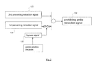
- Figure 2 is a logic diagram illustrating controlling retraction of the probe according to the first embodiment.
- Figure 3 is a logic diagram illustrating controlling retraction of the probe according to a second embodiment.
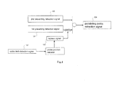
- Figure 4 is a logic diagram illustrating controlling retraction of the probe according to a third embodiment.
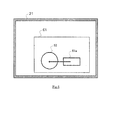
- Figure 5 is a block schematic diagram illustrating a moving mock probe device according to a fourth embodiment.
- Fig.1 shows a general Boiled Water Reactor (BWR) power plant.
- the traveling reactor power monitoring system is referred to as a Traversing In-core Probe (TIP) monitoring system 1.
- TIP Traversing In-core Probe
- the TIP monitoring system 1 moves a traveling probe referred to as a TIP 8 to measure neutron flux in the reactor core.
- a reactor pressure vessel 32 is stabilized in a reactor container 31, a reactor pressure vessel 32 is stabilized.
- a reactor core 33 is a portion where the fission fuel is loaded in the reactor pressure vessel 32.
- a number of LPRMs 34 are provided in the reactor core 33.
- a number of guide tubes 24 are provided near the LPRMs 34 ( Fig. 1 shows one guide tube 24). Each guide tube 24 and LPRMs 34 account for a sensor assembly 35.
- a TIP monitoring system 1 includes a TIP drive unit 2, a probe cable 7, a TIP 8 (travelling probe), a process calculator 14, a drive control unit 10, a probe signal monitoring unit 12, a field control panel 51, a proximity switch 52, and a cable limit switch 53.
- the TIP drive unit 2 includes a storage reel 3, a motor 4, and a probe position signal generator 6.
- the drive control unit 10, the probe signal monitoring unit 12, and the process calculator 14 may be provided in a central monitoring room 41.
- the TIP drive unit 2 is provided outside of the reactor container 31.
- One edge of the probe cable 7 is connected to the TIP 8, and the storage reel 3 may store the probe cable 7.
- the motor 4 is provided to feed the probe cable 7 from the storage reel 3 and spool the probe cable 7 onto the storage reel 3 by rotating the storage reel 3. Between the storage reel 3 and the motor 4, gears and crutch may be provided.
- the motor 4 can be connected to an inverter.
- the motor 4 receives supply power from the inverter to rotate at a speed indicated by a drive command 104.
- the probe position signal generator 6 is provided to monitor the length of spooling the probe cable 7 onto the reel 3.
- the probe position signal generator 6 sends the monitored cable length as the probe position signal 101.
- the drive control unit 10 is connected to the motor 4 and the indexing device 23 to send a drive command 104 to the motor 4 and send an indexing command to the indexing device 23 respectively.
- the field control panel 51 is connected to the cable limit switch 53, the proximity switch 52, and the probe position signal generator 6 to receive the cable limit switch detecting signal 122, the 1 st preventing retraction signal 121, and the probe position signal 101 respectively.
- the drive control unit 10 is connected to the field control panel 51 to receive the cable limit switch detecting signal 122, the 1stpreventing retraction signal 121, and the probe position signal 101.
- the TIP 8 may send a probe output signal 102 that indicates the measured neutron flux through a signal transmitting line in the probe cable 7.
- the TIP 8 is connected to the probe signal monitoring unit 12 to send the probe output signal 102 through the probe cable 7.
- a shielding vessel 21 is provided outside of the reactor container 31.
- the shielding vessel 21 may store and keep within it the TIP 8.
- a valve assembly 22 may be provided outside of the reactor container 31 and inside of the shielding vessel 21.
- An indexing device 23 is provided in the reactor container 31. The shielding vessel 21, the valve assembly 22, and the indexing device 23 are connected by a pipe to move the TIP 8 to the indexing device 23 from the shielding vessel 21 through the valve assembly 22.
- the valve assembly 22 may include a gas valve purging gas in the guide tubes 24 and a cutting valve cutting the pipe at an emergency situation. Furthermore, the valve assembly 22 can close the pipe without neutron monitoring.
- the guide tubes 24 are connected to the indexing device 23. Each guide tube 24 extends to under the reactor pressure vessel 32, and curves upwards. Furthermore, each guide tube 24 penetrates the bottom of the reactor pressure vessel 32, and extends vertically into the reactor core 33.
- the drive control unit 10 is connected to the process calculator 14 to send the probe position signal 101 to the process calculator 14. Furthermore, the probe signal monitoring unit 12 is connected to the process calculator 14 to send the probe output signal 102 to the process calculator 14.
- the proximity switch 52 is provided in the shielding vessel 21. When the TIP 8 exists at a predefined stop range in the shielding vessel 21, the proximity switch 52 outputs the 1stpreventing retraction signal 121.
- the proximity switch 52 is connected to the drive control unit 10 via the field control panel 51 to send the 1 st preventing retraction signal 121 to the drive control unit 10.
- the cable limit switch 53 may be provided at the indexing device 23.
- the cable limit switch 53 outputs the cable limit switch detecting signal 122 when the probe exists at the side of reactor pressure vessel 32 in relation to the indexing device 23.
- the cable limit switch 53 is connected to the drive control unit 10 via the field control panel 51 to send the cable limit switch detecting signal 122 to the drive control unit 10.
- measuring neutron flux is described as follows. Controlling retracting the TIP 8 is described later.
- the TIP 8 is stored in the shielding vessel 21.
- the drive control unit 10 sends the drive command 104 to the motor 4.
- the motor 4 feeds the probe cable 7 from the storage reel 3, and inserts the TIP 8 to the indexing device 23 from the shielding vessel 21.
- the drive control unit 10 sends an indexing command to the indexing device 23.
- the indexing device 23 indexes the TIP 8 to a designated guide tube 24 in which to measure neutron flux.
- the drive control unit 10 further drives the motor 4 and inserts the TIP 8 into the designated guide tube 24.
- the drive control unit 10 receives the probe position signal 101 from the probe position signal generator 6, and recognizes the insert position of the TIP 8 in the designated guide tube 24.
- the TIP 8 measures neutron flux at predefined points during moving in the guide designated tube 24, and sends the probe output signal 102 to the probe signal monitoring unit 12 through the probe cable 7.
- the process calculator 14 calculates the power distribution at each probe position in the reactor core by using the probe output signal 102 and the probe position signal 101, and calculates the value for calibrating the LPRMs 34.
- the drive control unit 10 After moving the TIP 8 to the predefined end point of the guide tube 24, the drive control unit 10 reverses motor 4 and spools the probe cable 7 onto the storage reel 4, and retracts the TIP 8 back to the indexing device 23. If it is necessary to measure neutron flux in another guide tube 24, the drive control unit 10 sends the indexing command 105 to the indexing device 23, and the indexing device 23 indexes the TIP 8 to another guide tube 24, and the drive control unit 10 moves the TIP 8 in the another guide tube 24.
- the drive control unit 10 retracts the TIP 8 to the shielding vessel 21 by spooling the probe cable 7 onto the storage reel 3 and stores the TIP 8 in the shielding vessel 21.
- the proximity switch 52 detects the TIP 8 at a predefined stop range, and generates the 1stpreventing retraction signal 121.
- the drive control unit 10 stops retracting the TIP 8 upon receiving the 1stpreventing retraction signal 121.
- the driving control unit 10 determines the probe position by the probe position signal 101.
- the driving control unit 10 may generate the 2ndpreventing retraction signal 123 as shown Fig.2 .
- the driving control unit 10 may also stop a retracting operation by this 2ndpreventing retraction signal 123.
- Fig.2 shows the inner logic of the drive control unit 10. This logic generates the prohibiting probe retraction signal 124 when the 1stpreventing retraction signal 121 or the 2ndpreventing retraction signal 123 is input.
- the drive control unit 10 stops the retracting operation of the TIP 8 when the prohibiting probe retraction signal 124 is generated.
- the drive control unit 10 determines the probe position by the probe position signal 101.
- This probe position signal 101 is probe information indicating the probe position as a substitute for a detection by the proximity switch 52 (for example if the proximity switch 52 is malfunctioning). If the probe position exceeds a predefined upper threshold, the drive control unit 10 sends the bypass signal 125 to the 1st preventing retraction signal 121.
- this upper threshold may be set at a value indicating that the TIP 8 exists out of the shielding vessel 21.
- the 1stpreventing retraction signal 121 is not sent when the TIP 8 is outside of the predefined stop range.
- the bypass signal 125 regardless of the bypass signal 125, the retracting operation is permitted. And the alarm is not generated because the above mentioned wipe out (WO) is not executed.
- the 1 stpreventing retraction signal 121 prevents the retracting operation.
- the proximity switch 52 is provided at a near side of the reactor pressure vessel 32 and is difficult to repair and replace compared to the drive control unit 10. Therefore, by putting priority on the drive control unit 10 above the proximity switch 52, the frequency of repairing and replacing the proximity switch 52 is decreased, and exposure dosage of utility workers is decreased.
- This embodiment differs from the first embodiment in that the drive control unit 10 sends the bypass signal 125 on the basis of a probe inserting operation.
- Information indicating the probe inserting operation is obtained by the drive command 104 of the drive control unit 10, or an operation command to the drive control unit 10 from a control desk.
- Fig.3 shows the inner logic of the drive control unit 10 in this second embodiment.
- the drive control unit 10 detects the inserting status of the TIP 8 by the drive command 104.
- the drive command 104 can be used as probe information indicating the probe position as a substitute for an output from the proximity switch 52.
- the drive control unit 10 determines the inserting operation, the drive control unit 10 sends the bypass signal 125 to the 1stpreventing retraction signal 121. And the 1stpreventing retraction signal 121 is overridden or wiped out (WO). As a result, the impossibility of retracting the TIP 8 due to a poor working condition of the proximity switch 52 is prevented. Furthermore, when the wipe out (WO) is executed, the drive control unit 10 may generate an alarm at the central monitoring room 41.
- the proximity switch 52 in a good working condition also generates the 1stpreventing retraction signal 121 at a predefined stop range in the shielding vessel 21. Therefore, at the starting inserting operation, after the TIP 8 passes the predefined stop range from the stored point in the shielding vessel 21 or after a predefined time has passed, the drive control unit 10 generates the bypass signal 125.
- the 1stpreventing retraction signal 121 is not sent at inserting operation, the retracting operation is permitted despite the bypass signal 125 being sent. Furthermore, the alarm is not generated because the wipe out (WO) is not executed.
- This embodiment differs from the first embodiment in that the bypass signal 125 is generated on the basis of a cable limit switch detecting signal 122 from the cable limit switch 53.
- the cable limit switch detecting signal 122 indicates that the TIP 8 exists at the side of the reactor pressure vessel 32.
- the cable limit switch 53 can be a simple probe detector that is provided at the guide tube 23 and sends the probe detecting signal when the TIP 8 exists at the side of the reactor pressure vessel 32. This probe detecting signal can then be used as probe information indicating the probe position as a substitute for an output of the proximity switch 52.
- the proximity switch 52 When the TIP 8 exists at the side of pressure vessel 32, if the proximity switch 52 generates the 1stpreventing retraction signal 121, there is a possibility that the proximity switch 52 is in a poor working condition or is malfunctioning, since the TIP 8 is not actually at the predefined stop range.
- the drive control unit 10 determines that the TIP 8 exists at the side of pressure vessel 32 (outside of the predefined stop range). The drive control unit 10 then sends the bypass signal 125 to the 1stpreventing retraction signal 121.
- the 1stpreventing retraction signal 121 is generated by the proximity switch 52 in a poor or malfunctioning working condition, the 1 stpreventing retraction signal 121 is wiped out (WO) by bypass signal 125. As a result, the impossibility of retracting the TIP 8 is prevented. Furthermore, at the bypass operation, the drive control unit 10 may generate an alarm at central monitoring room 41.
- the bypass signal 125 can be input.
- the 1stpreventing retraction signal 121 is overridden or wiped out only by receiving the cable limit switch detecting signal 122.
- the composition of the TIP monitoring system 1 is more simplified than the first embodiment determining the probe position by the probe position signa1101.
- This embodiment differs from the first embodiment in that, as shown in Fig. 5 , amoving mock probe device 61 is provided in the shielding vessel 21. As shown Fig.5 , the moving mock probe device 61 may move a metallic piece 61a as a mock travelling probe in the shielding vessel 21.
- the moving mock probe device 61 moves the metallic piece 61a close to the proximity switch 52, and the proximity switch 52 generates the signal 121 by the metallic piece 61a.
- the 1stpreventing retraction signal 121 is generated by the metallic piece 61a, the poor working condition of the drive control unit 10 is detected.
- guide tubes 24 penetrate an upper portion of the reactor pressure vessel, and the traveling probe moves to the core bottom from the core top.
- the traveling power monitoring system can connect a gamma thermo meter as the traveling probe. This gamma thermo meter can measure gamma rays in the reactor core during moving. In this case, the traveling power monitoring system can measure gamma rays as reactor power.
Landscapes
- Physics & Mathematics (AREA)
- Engineering & Computer Science (AREA)
- Plasma & Fusion (AREA)
- General Engineering & Computer Science (AREA)
- High Energy & Nuclear Physics (AREA)
- Monitoring And Testing Of Nuclear Reactors (AREA)
- Investigating Or Analyzing Materials By The Use Of Ultrasonic Waves (AREA)
Applications Claiming Priority (1)
| Application Number | Priority Date | Filing Date | Title |
|---|---|---|---|
| JP2012072520A JP5711690B2 (ja) | 2012-03-27 | 2012-03-27 | 移動式原子炉出力測定装置およびその移動式検出器の引抜き制御方法 |
Publications (2)
| Publication Number | Publication Date |
|---|---|
| EP2645372A2 true EP2645372A2 (fr) | 2013-10-02 |
| EP2645372A3 EP2645372A3 (fr) | 2017-04-12 |
Family
ID=47891486
Family Applications (1)
| Application Number | Title | Priority Date | Filing Date |
|---|---|---|---|
| EP13159453.3A Withdrawn EP2645372A3 (fr) | 2012-03-27 | 2013-03-15 | Système mobile de surveillance de puissance d'un réacteur et procédé de commande de rétractation de sonde |
Country Status (3)
| Country | Link |
|---|---|
| US (1) | US20130259182A1 (fr) |
| EP (1) | EP2645372A3 (fr) |
| JP (1) | JP5711690B2 (fr) |
Cited By (1)
| Publication number | Priority date | Publication date | Assignee | Title |
|---|---|---|---|---|
| CN116825411A (zh) * | 2023-07-12 | 2023-09-29 | 江苏核电有限公司 | 一种核反应堆堆芯探测器卷出装置工作轴驱动与控制方法 |
Families Citing this family (4)
| Publication number | Priority date | Publication date | Assignee | Title |
|---|---|---|---|---|
| US20160012928A1 (en) * | 2014-07-08 | 2016-01-14 | Westinghouse Electric Company Llc | Targeted Isotope Production System |
| WO2016147374A1 (fr) * | 2015-03-19 | 2016-09-22 | 三菱電機株式会社 | Dispositif de commande de dispositif d'instrumentation nucléaire dans le réacteur |
| WO2018096579A1 (fr) * | 2016-11-22 | 2018-05-31 | 三菱電機株式会社 | Dispositif d'instrumentation nucléaire interne au cœur |
| CN114005560B (zh) * | 2021-10-22 | 2023-07-04 | 华能核能技术研究院有限公司 | 一种高温气冷堆吸收球落球限位装置及球床式高温气冷堆 |
Citations (1)
| Publication number | Priority date | Publication date | Assignee | Title |
|---|---|---|---|---|
| JP2002071483A (ja) | 2000-08-31 | 2002-03-08 | Toshiba Corp | 移動式炉内計装系トルク測定装置 |
Family Cites Families (8)
| Publication number | Priority date | Publication date | Assignee | Title |
|---|---|---|---|---|
| US3932211A (en) * | 1973-07-13 | 1976-01-13 | Westinghouse Electric Corporation | Method of automatically monitoring the power distribution of a nuclear reactor employing movable incore detectors |
| JPS54106789A (en) * | 1978-02-10 | 1979-08-22 | Hitachi Ltd | Controller for moving-type inside-reactor neutron detector |
| JPS5780598A (en) * | 1980-11-07 | 1982-05-20 | Hitachi Ltd | Method of recording data for reactor power calibration |
| JPS58165092A (ja) * | 1982-03-25 | 1983-09-30 | 株式会社東芝 | 駆動監視装置 |
| US5096658A (en) * | 1990-03-16 | 1992-03-17 | Westinghouse Electric Corp. | Detector path insertion verification system |
| US5078956A (en) * | 1990-07-31 | 1992-01-07 | Westinghouse Electric Corp. | Neutron flux detector distribution system with improved drivability |
| JPH0616899U (ja) * | 1992-08-07 | 1994-03-04 | 東芝エンジニアリング株式会社 | Tip試験装置 |
| JP3800396B2 (ja) * | 2000-12-13 | 2006-07-26 | 株式会社日立製作所 | 原子炉出力測定装置 |
-
2012
- 2012-03-27 JP JP2012072520A patent/JP5711690B2/ja not_active Expired - Fee Related
-
2013
- 2013-03-13 US US13/800,639 patent/US20130259182A1/en not_active Abandoned
- 2013-03-15 EP EP13159453.3A patent/EP2645372A3/fr not_active Withdrawn
Patent Citations (1)
| Publication number | Priority date | Publication date | Assignee | Title |
|---|---|---|---|---|
| JP2002071483A (ja) | 2000-08-31 | 2002-03-08 | Toshiba Corp | 移動式炉内計装系トルク測定装置 |
Cited By (1)
| Publication number | Priority date | Publication date | Assignee | Title |
|---|---|---|---|---|
| CN116825411A (zh) * | 2023-07-12 | 2023-09-29 | 江苏核电有限公司 | 一种核反应堆堆芯探测器卷出装置工作轴驱动与控制方法 |
Also Published As
| Publication number | Publication date |
|---|---|
| US20130259182A1 (en) | 2013-10-03 |
| JP2013205119A (ja) | 2013-10-07 |
| EP2645372A3 (fr) | 2017-04-12 |
| JP5711690B2 (ja) | 2015-05-07 |
Similar Documents
| Publication | Publication Date | Title |
|---|---|---|
| EP2418650B1 (fr) | Unité de commande de sonde interne traversante et procédé pour surveiller la friction à l'intérieur des tubes guides | |
| EP2645372A2 (fr) | Système mobile de surveillance de puissance d'un réacteur et procédé de commande de rétractation de sonde | |
| US11031143B2 (en) | Systems and methods of monitoring control rods of nuclear power plants | |
| CN104798138B (zh) | 验证核反应堆容器内检测器输出信号的方法 | |
| EP2071360B1 (fr) | Dispositif d'étalonnage et de surveillance de sonde interne transversale pour des centrales nucléaires, et procédé associé | |
| CN110689974A (zh) | 一种基于瞬时伽马响应修正的改进堆芯功率分布的测量方法 | |
| US10229763B2 (en) | Neutron flux mapping system and control method for neutron flux mapping system | |
| EP2639796B1 (fr) | Système traversant de surveillance de puissance d'un réacteur et procédé de surveillance de couple d'entraînement | |
| KR940003801B1 (ko) | 낙하된 제어봉을 가진 원자로를 제어하는 장치 및 방법 | |
| US20240387068A1 (en) | Systems for periodically measuring the total gamma radiation activity of a target radioisotope being produced inside the core of a nuclear reactor | |
| JP4592397B2 (ja) | 移動式原子炉内中性子測定装置およびその方法 | |
| JP2014052258A (ja) | 原子炉の放射線計測装置 | |
| EP2618334B1 (fr) | Système de surveillance de la puissance d'un réacteur par une sonde de déplacement et procédé de commande d'une sonde de déplacement | |
| CN114895348A (zh) | 沉淀反应器核临界安全的监测系统 | |
| JP6165390B1 (ja) | 炉内核計装装置 | |
| CN223598419U (zh) | 一种核反应堆探测器组件的屏蔽装置及回收系统 | |
| US5425064A (en) | Nuclear turbine coolant flow meter | |
| JP2013002973A (ja) | Tipシステムおよびtip監視制御装置 | |
| CN119716965B (zh) | 一种采用内置液体放射源进行校准的探测器 | |
| JP4052618B2 (ja) | 原子炉炉内監視装置 | |
| Düweke et al. | Neutron flux incore instrumentation of AREVA's EPR™ | |
| KR20100004573U (ko) | 이동형 노내 중성자속 분포 검출장치 | |
| JPH06308281A (ja) | 可動インコアプローブモニタ | |
| JP2014145720A (ja) | 未臨界度測定装置および未臨界維持システム |
Legal Events
| Date | Code | Title | Description |
|---|---|---|---|
| PUAI | Public reference made under article 153(3) epc to a published international application that has entered the european phase |
Free format text: ORIGINAL CODE: 0009012 |
|
| 17P | Request for examination filed |
Effective date: 20130315 |
|
| AK | Designated contracting states |
Kind code of ref document: A2 Designated state(s): AL AT BE BG CH CY CZ DE DK EE ES FI FR GB GR HR HU IE IS IT LI LT LU LV MC MK MT NL NO PL PT RO RS SE SI SK SM TR |
|
| AX | Request for extension of the european patent |
Extension state: BA ME |
|
| PUAL | Search report despatched |
Free format text: ORIGINAL CODE: 0009013 |
|
| AK | Designated contracting states |
Kind code of ref document: A3 Designated state(s): AL AT BE BG CH CY CZ DE DK EE ES FI FR GB GR HR HU IE IS IT LI LT LU LV MC MK MT NL NO PL PT RO RS SE SI SK SM TR |
|
| AX | Request for extension of the european patent |
Extension state: BA ME |
|
| RIC1 | Information provided on ipc code assigned before grant |
Ipc: G21C 17/108 20060101AFI20170306BHEP Ipc: G21D 1/00 20060101ALI20170306BHEP Ipc: G21C 19/20 20060101ALI20170306BHEP |
|
| STAA | Information on the status of an ep patent application or granted ep patent |
Free format text: STATUS: REQUEST FOR EXAMINATION WAS MADE |
|
| STAA | Information on the status of an ep patent application or granted ep patent |
Free format text: STATUS: THE APPLICATION IS DEEMED TO BE WITHDRAWN |
|
| 18D | Application deemed to be withdrawn |
Effective date: 20171013 |