EP2645722A1 - Bildgebungsvorrichtung und verfahren zur steuerung von deren betrieb - Google Patents
Bildgebungsvorrichtung und verfahren zur steuerung von deren betrieb Download PDFInfo
- Publication number
- EP2645722A1 EP2645722A1 EP11861172.2A EP11861172A EP2645722A1 EP 2645722 A1 EP2645722 A1 EP 2645722A1 EP 11861172 A EP11861172 A EP 11861172A EP 2645722 A1 EP2645722 A1 EP 2645722A1
- Authority
- EP
- European Patent Office
- Prior art keywords
- light component
- transmitting
- color
- optoelectronic transducers
- filter
- Prior art date
- Legal status (The legal status is an assumption and is not a legal conclusion. Google has not performed a legal analysis and makes no representation as to the accuracy of the status listed.)
- Withdrawn
Links
Images







Classifications
-
- G—PHYSICS
- G06—COMPUTING OR CALCULATING; COUNTING
- G06T—IMAGE DATA PROCESSING OR GENERATION, IN GENERAL
- G06T3/00—Geometric image transformations in the plane of the image
- G06T3/40—Scaling of whole images or parts thereof, e.g. expanding or contracting
- G06T3/4015—Image demosaicing, e.g. colour filter arrays [CFA] or Bayer patterns
-
- H—ELECTRICITY
- H04—ELECTRIC COMMUNICATION TECHNIQUE
- H04N—PICTORIAL COMMUNICATION, e.g. TELEVISION
- H04N23/00—Cameras or camera modules comprising electronic image sensors; Control thereof
- H04N23/10—Cameras or camera modules comprising electronic image sensors; Control thereof for generating image signals from different wavelengths
- H04N23/12—Cameras or camera modules comprising electronic image sensors; Control thereof for generating image signals from different wavelengths with one sensor only
-
- H—ELECTRICITY
- H04—ELECTRIC COMMUNICATION TECHNIQUE
- H04N—PICTORIAL COMMUNICATION, e.g. TELEVISION
- H04N23/00—Cameras or camera modules comprising electronic image sensors; Control thereof
- H04N23/80—Camera processing pipelines; Components thereof
- H04N23/84—Camera processing pipelines; Components thereof for processing colour signals
- H04N23/843—Demosaicing, e.g. interpolating colour pixel values
-
- H—ELECTRICITY
- H04—ELECTRIC COMMUNICATION TECHNIQUE
- H04N—PICTORIAL COMMUNICATION, e.g. TELEVISION
- H04N25/00—Circuitry of solid-state image sensors [SSIS]; Control thereof
- H04N25/10—Circuitry of solid-state image sensors [SSIS]; Control thereof for transforming different wavelengths into image signals
- H04N25/11—Arrangement of colour filter arrays [CFA]; Filter mosaics
- H04N25/13—Arrangement of colour filter arrays [CFA]; Filter mosaics characterised by the spectral characteristics of the filter elements
- H04N25/134—Arrangement of colour filter arrays [CFA]; Filter mosaics characterised by the spectral characteristics of the filter elements based on three different wavelength filter elements
-
- H—ELECTRICITY
- H04—ELECTRIC COMMUNICATION TECHNIQUE
- H04N—PICTORIAL COMMUNICATION, e.g. TELEVISION
- H04N25/00—Circuitry of solid-state image sensors [SSIS]; Control thereof
- H04N25/70—SSIS architectures; Circuits associated therewith
- H04N25/71—Charge-coupled device [CCD] sensors; Charge-transfer registers specially adapted for CCD sensors
- H04N25/73—Charge-coupled device [CCD] sensors; Charge-transfer registers specially adapted for CCD sensors using interline transfer [IT]
Definitions
- This invention relates to an image sensing apparatus and to a method of controlling the operation of this apparatus.
- Fig. 8a illustrates part of the photoreceptor surface of a solid-state electronic image sensing device 1.
- the solid-state electronic image sensing device 1 is provided with a number of optoelectronic transducers 2 in the horizontal and vertical directions.
- Formed on the photoreceptor surfaces of the optoelectronic transducers 2 are color filters R having a characteristic that transmits a light component of the color red, color filters G having a characteristic that transmits a light component of the color green, or color filters B having a characteristic that transmits a light component of the color blue.
- the color filters R,G or B are formed on the photoreceptor surfaces of the optoelectronic transducers 2 in an array referred to as the "Bayer array".
- Fig. 8b illustrates the manner in which an image having a period that corresponds to three columns of the optoelectronic transducers 2 of the solid-state electronic image sensing device 1 is formed on the solid-state electronic image sensing device 1.
- the level of the white-color portions is 255 if expressed by eight bits and the level of the portions indicated by the hatching is 0 if expressed by eight bits. If subsampling processing, which is for reading out signal charge that has accumulated in a (3n+1)th row (where n is a positive integer), is executed in a case where such an image has been formed, high-frequency components repeat and a bright, flat Moiré image is produced, as shown in Fig. 8c .
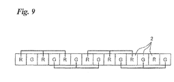
- Fig. 9 illustrates one row of optoelectronic transducers of the solid-state electronic image sensing device 1 shown in Fig. 8a .
- Signal charge that has accumulated in optoelectronic transducers 2 on which color filters having identical characteristics have been formed are mixed along the horizontal direction. Since every other color filter has the same characteristic, the resolution of the image after the pixels are mixed declines as if it were passed through a low-pass filter.
- Patent No. 4019417 there is a technique (Patent No. 4019417 ) in which two each of pixels having green color components are formed along each of the horizontal and vertical directions.
- a sensitivity adjustment is required in a case where pixels having green color components are utilized.
- An object of the present invention is to achieve higher resolution even in cases where pixels are subsampled.
- An image sensing apparatus is characterized by comprising: a solid-state electronic image sensing device having a number of optoelectronic transducers arrayed in horizontal and vertical directions, wherein color filters having filter characteristics for transmitting a light component of any color among colors red, green and blue or a light component of any color among colors cyan, magenta and yellow are formed on photoreceptor surfaces of the optoelectronic transducers, the number of the optoelectronic transducers on the photoreceptor surfaces of which the color filters having the filter characteristic for transmitting the green light component are formed is greater than the number of the optoelectronic transducers on the photoreceptor surfaces of which the color filters having the filter characteristic for transmitting the red light component are formed or the number of the optoelectronic transducers on the photoreceptor surfaces of which the color filters having the filter characteristic for transmitting the blue light component are formed, or the number of the optoelectronic transducers on the photoreceptor surfaces of which the
- the present invention also provides an operation control method suited to the above-described image sensing apparatus.
- the invention provides a method comprises: a solid-state electronic image sensing device, which has a number of optoelectronic transducers arrayed in horizontal and vertical directions, outputting signal charge, which has accumulated in the optoelectronic transducers, as a video signal, wherein color filters having a filter characteristic for transmitting a light component of any color among colors red, green and blue or a light component of any color among colors cyan, magenta and yellow are formed on photoreceptor surfaces of the optoelectronic transducers, the number of the optoelectronic transducers on the photoreceptor surfaces of which the color filters having the filter characteristic for transmitting the green light component are formed is greater than the number of the optoelectronic transducers on the photoreceptor surfaces of which the color filters having the filter characteristic for transmitting the red light component are formed or the number of the optoelectronic transducers on the photo
- pixels having a green or yellow light component from among pixels that constitute an image represented by a video signal that is output from a solid-state electronic image sensing device it is arranged so that these pixels are included in all horizontal, vertical and diagonal directions in a block consisting of six pixels in both the horizontal and vertical directions, in the same manner as an array of color filters, which have a characteristic that transmits a green or yellow light component, formed on the photoreceptor surfaces of optoelectronic transducers that construct a solid-state electronic image sensing device.
- the image represented by a video signal that is output from the solid-state electronic image sensing device is such that there is an improvement in the precision of reproducibility of interpolation processing in the high-frequency region.
- the above-mentioned block is a group of four sub-blocks each consisting of three of the optoelectronic transducers in each of the horizontal and vertical directions.
- an array of color filters having a characteristic for transmitting a red or cyan light component and an array of color filters having a characteristic for transmitting a blue or magenta light component would be the reverse of each other in sub-blocks adjacent in the horizontal direction and in the vertical direction.
- It may be arranged so as to include at least one portion in which two color filters, which have a characteristic for transmitting a green or yellow light component, formed on the photoreceptor surfaces of the optoelectronic transducers contained in the block are contiguous in all of the horizontal, vertical and diagonal directions.
- It may be arranged so as to include at least one portion in which two color filters each, which have a characteristic for transmitting a green or yellow light component, formed on the photoreceptor surfaces of the optoelectronic transducers contained in the block are contiguous in the horizontal and vertical directions.
- the apparatus may further comprise: a correlation direction detection device (correlation direction detection means) for detecting a correlation direction from pixel levels of four pixels obtained based upon a portion in which two of the color filters each, which have a characteristic for transmitting a green or yellow light component, formed on the photoreceptor surfaces of the optoelectronic transducers contained in the block are contiguous in the horizontal and vertical directions; an interpolation device (interpolation means) for interpolating a green or yellow component of a pixel having a red, cyan, blue or magenta component, which exists in the correlation direction detected in the correlation direction detection device, by using a pixel having a green or yellow component that exists in the correlation direction detected in the correlation direction detection device; and a control device (control means) for repeating processing by the correlation direction detection device and processing by the interpolation device with regard to one image portion.
- a correlation direction detection device correlation direction detection means for detecting a correlation direction from pixel levels of four pixels obtained based upon a portion in which two of the
- the correlation direction detection device calculates an absolute value of a difference between pixel levels of adjacent pixels in every one of the horizontal, vertical and diagonal directions and decides that a direction along which the sum total or average value of the absolute values of the differences in every direction is smallest is the correlation direction.
- the interpolation device interpolates a color component, which does not have a color component among pixels having the red, cyan, blue or magenta color component, from a green or yellow color component interpolated by the interpolation device and a color component having a color component among pixels having the red, cyan, blue or magenta color component.
- the optoelectronic transducers on which the color filters having the characteristic for transmitting the green or yellow light component are formed have equal sensitivities.
- Fig. 1 illustrates part of the photoreceptor surface of a CCD (which may be another solid-state electronic image sensing device such as a C-MOS) 10 according to an embodiment of the present invention.
- a CCD which may be another solid-state electronic image sensing device such as a C-MOS
- a number of optoelectronic transducers 11 are arrayed in the horizontal direction (indicated by arrow H) and vertical direction (indicated by arrow V).
- the sensitivities of these optoelectronic transducers 11 are all equal (the sensitivities of optoelectronic transducers on which filters for transmitting at least a green light component have been formed are equal).
- Formed on the photoreceptor surfaces of the optoelectronic transducers 11 are color filters R, G or B having characteristics for transmitting red, green or blue (which may just as well be cyan, yellow or magenta) light components.
- a red filter having a characteristic for transmitting the red light component is indicated by character R
- a green filter having a characteristic for transmitting the green light component by character G
- a blue filter having a characteristic for transmitting the blue light component by character B.
- the block 20 will contain at least one green filter G, one blue filter B and one red filter R.
- at least one green filter G will be formed along all of the horizontal, vertical and diagonal directions.
- the photoreceptor surface of the CCD 10 is formed by color filters arrayed in this fashion.
- the block 20 can be considered to be a group of four sub-blocks 21 to 24 each consisting of three optoelectronic transducers 11 in each of the horizontal and vertical directions.
- Color filters formed on the photoreceptor surfaces of the optoelectronic transducers 11 at the center of sub-block 21 and along the diagonal directions through this center are the green filters G.
- Color filters formed on the photoreceptor surfaces of the optoelectronic transducers 11 on both sides of the center of sub-block 21 along the horizontal direction are the red filters R, and color filters formed on the photoreceptor surfaces of the optoelectronic transducers 11 on both sides of the center of sub-block 21 along the vertical direction are the blue filters B.
- the filter array of optoelectronic transducers 11 contained in sub-block 24 situated diagonally to the lower right of sub-block 21 is identical with the filter array of sub-block 21.
- the filter arrays of optoelectronic transducers 11 contained in sub-block 22 situated on the right side of sub-block 21 and in sub-block 23 situated on the lower side of sub-block 21 are, with regard to the color filters G, identical with the array of green filters G formed on the optoelectronic transducers 11 contained in sub-block 21, but are the reverse with regard to the red filters R and blue filters B in sub-block 21.
- the red filters R are formed on the photoreceptor surfaces of optoelectronic transducers 11 on both sides of the center optoelectronic transducer 11 along the vertical direction
- the blue filters B are formed on the photoreceptor surfaces of optoelectronic transducers 11 on both sides of the center optoelectronic transducer 11 along the horizontal direction.
- the precision of reproducibility of interpolation processing in the high-frequency region can be improved because the pixels that constitute the image of the subject obtained by imaging contain green components along each of the horizontal, vertical and diagonal directions. Similarly, the occurrence of false colors can be prevented since red and blue components are included along each of the horizontal and vertical directions.
- block 20 contains portions in which two of the green filters G are contiguous in all of the horizontal, vertical and diagonal directions. Further, block 20 also contains portions in which two of the green filters G each are contiguous in the horizontal and vertical directions.
- Fig. 2 is an example of an image (a portion thereof) obtained by subsampling processing, which is executed in the CCD 10 having the array of color filters described above, for extracting every other pixel (odd-numbered) along each of the horizontal and vertical directions from an image obtained by imaging a subject.
- An image portion 30 consists of six pixels 35 along each of the horizontal and vertical directions.
- the image portion 30 corresponds to the block 20 shown in Fig. 1 .
- the image portion 30 consists of four sub-blocks 31 to 34 of three pixels each along each of the horizontal and vertical directions.
- the sub-blocks 31 to 34 are such that pixels 35 having the green component are all situated at the centers of the sub-blocks and along the diagonal directions through these centers.
- the pixels on both sides of the center green-component pixel 35 along the horizontal direction are pixels 35 having the red component
- the pixels on both sides of the center green-component pixel 35 along the vertical direction are pixels 35 having the blue component.
- the placement of the blue filters B and the placement of the red filters R are the reverse of each other in the sub-blocks that are mutually adjacent along the horizontal direction and along the vertical direction in block 20 shown in Fig. 1 , whereas the placement of the blue filters B and the placement of the red filters R are the same, irrespective of the sub-blocks 31 to 34, in the image portion 30 shown in Fig. 2 .
- the precision of reproducibility of interpolation processing in the high-frequency region can be improved because green components are contained along each of the horizontal, vertical and diagonal directions.
- the reproducibility of interpolation processing can be improved even with regard to an image that has been subjected to subsampling processing as by raising the frame rate.
- the image portion 30 shown in Fig. 2 is obtained by subsampling pixels in odd-numbered rows and odd-numbered columns. However, even if pixels in even-numbered rows and even-numbered columns, odd-numbered rows and even-numbered column or even-numbered rows and odd-numbered columns are subsampled, a subsampled image containing green components along each of horizontal, vertical and diagonal directions in an image portion of 6 pixels x 6 pixels will be obtained in a manner similar to that of the image portion shown in Fig. 2 .
- Fig. 3 illustrates part of the photoreceptor surface of the CCD 10 shown in Fig. 1 .
- vertical transfer lines 12, a horizontal transfer line 13 and an amplifying circuit 14 have been added on.
- a number of the optoelectronic transducers 11 are arrayed in the horizontal direction (indicated by arrow H) and vertical direction (indicated by arrow V). Further, formed on the photoreceptor surfaces of these optoelectronic transducers 11 are any one of a red filter R, green filter G and blue filter B.
- the array of color filters is the same as that shown in Fig. 1 .
- the amplifying circuit 14 is connected to the output side of the horizontal transfer line 13.
- the optoelectronic transducers 11 By exposing the optoelectronic transducers 11 to light, signal charge accumulates in the optoelectronic transducers 11. Signal charge representing pixels of the red, green or blue components accumulates in the optoelectronic transducers 11 on which the red filters R, green filters G or blue filters B have been formed.
- the signal charge that has accumulated in the optoelectronic transducers 11 is shifted to the vertical transfer lines 12 by application of a shift pulse to the optoelectronic transducers 11.
- the signal charge thus shifted to the vertical transfer lines 12 is transferred in the vertical direction by application of a vertical-transfer pulse ⁇ V to the vertical transfer lines 12, and the signal charge that has been transferred through the vertical transfer lines is applied to the horizontal transfer line 13 by application of a shift pulse.
- the signal charge applied to the horizontal transfer line 13 is transferred in the horizontal direction by application of a horizontal transfer pulse ⁇ H.
- the signal charge that has been transferred in the horizontal direction is output from the CCD
- subsampling processing is executed in the solid-state electronic image sensing device 10.
- it may be arranged so that subsampling processing is applied to the video signal, which is output from the solid-state electronic image sensing device 10, without executing subsampling processing in the solid-state electronic image sensing device 10.
- a video signal equivalent to one image that has been output from the solid-state electronic image sensing device 10 would be stored in a memory and the video signal would be read out of the memory every other pixel along the horizontal and vertical directions.
- Fig. 4 illustrates an image portion 40 obtained by executing subsampling processing in the manner set forth above.
- numerals have been appended to the right side of each R, G or B character in Fig. 4 .
- Character R represents a red filter, G a green filter and B a blue filter, which is similar to the arrangement described above.
- the image portion 40 has five pixels in each of the horizontal and vertical directions (though it goes without saying that the number of pixels need not be five each).
- a central sub-block 41 comprising three pixels along each of the horizontal and vertical directions
- a direction discrimination sub-block 42 which is at the upper right, comprising three pixels along each of the horizontal and vertical directions.
- Fig. 5 illustrates the direction discrimination sub-block 42.
- the direction discrimination sub-block 42 includes four pixels G14, G15, G24 and G25. These pixels G14, G15, G24 and G25 each have the green component but not the blue and red components.
- the absolute value of the difference between the levels of the pixels G14, G15, G24 and G25 is calculated along each of the horizontal (indicated by arrow H), vertical (indicated by arrow V) and diagonal directions, and the direction along which the calculated absolute value of the differences is smallest is decided upon as a correlation direction.
- the upper-right diagonal direction is discriminated to be the correlation direction by utilizing the direction discrimination sub-block 42, then the green component of pixel B23 contained in sub-block 41 is interpolated using the pixel G14 contained in the direction discrimination sub-block 42, and the green component of pixel R34 contained in sub-block 41 is interpolated using the pixel G25.
- the horizontal direction is discriminated to be the correlation direction by utilizing the direction discrimination sub-block 42, then the green component of pixel B23 contained in sub-block 41 is interpolated using the pixel G24 contained in the direction discrimination sub-block 42, and the green component of pixel R34 contained in sub-block 41 is interpolated using the pixel G33.
- the vertical direction is discriminated to be the correlation direction by utilizing the direction discrimination sub-block 42, then the green component of pixel B23 contained in sub-block 41 is interpolated using the pixel G33, and the green component of pixel R34 contained in sub-block 41 is interpolated using the pixel G24 contained in the direction discrimination sub-block 42.
- each of direction discrimination sub-blocks 42, 44, 45 and 46 located at the four corners in Fig. 4 and each comprising 2 x 2 pixels the absolute values of the differences along the horizontal, vertical, upper-left and upper-right diagonal directions are calculated, the sum total (average) of the calculated absolute values of the differences is calculated according to direction and the direction along which the obtained sum total (average) is smallest may be adopted as the correlation direction.
- the green component of the blue pixel B23 and the green component of the red pixel R34 are interpolated, but the red component of the blue pixel B23 and the blue component of the red pixel R34 are not.
- red and blue components can be interpolated similarly with regard to the green pixel.
- the method of interpolating the pixel value of a pixel of interest based upon the color difference relative to a neighboring pixel and calculating the pixel value of another color is as follows:
- a pixel of interest to undergo interpolation processing be a green pixel G, and let this pixel value be G.
- the pixel value of the pixel of interest is interpolated based upon the color difference relative to a neighboring pixel of another color and the pixel value of the other color is calculated.
- this does not impose a limitation and, as set forth next, it may be arranged to interpolate the pixel value of a pixel of interest based upon a color comparison with a neighboring pixel of another color and calculate the pixel value of the other color.
- a pixel of interest to undergo interpolation processing is a blue pixel B
- the pixel value thereof is B
- a green pixel G or red pixel R does not exist along the discriminated correlation direction
- Fig. 6 is a block diagram illustrating part of the electrical configuration of a digital camera (inclusive of a digital still camera, digital movie camera and mobile telephone provided with the function of a digital camera).
- the overall operation of the movie camera is controlled by a control unit 60.
- the image of a subject is formed on the photoreceptor surface of the above-mentioned CCD 10 by an imaging lens 61.
- the CCD 10 is driven by a driving unit 64.
- the driving unit 64 applies pulses such as the shift pulse, vertical transfer pulse ⁇ V and horizontal transfer pulse ⁇ H to the CCD 10 so as to execute subsampling processing as described above.
- a subsampled video signal is output from the CCD 10 and is input to an imaging processor 62.
- the imaging processor 62 executes predetermined imaging processing such as an analog/digital conversion, gamma correction and white balance adjustment. As mentioned above, it may be arranged so that subsampling processing is executed in the imaging processor 62 and not in the CCD 10. In such case the imaging processor 62 would include a memory for storing image data temporarily and subsampling processing would be executed, as set forth above, when the image data is read out of the memory.
- the image data that has been output from the imaging processor 62 is input to an image processing unit 63.
- Direction discrimination and the like are executed, as set forth above, in the image processing unit 63 and interpolation processing is executed in accordance with the discriminated direction.
- Interpolated color image data is output from the image processing unit 63. It should be noted that in the foregoing embodiment, it is possible to apply interpolation processing based upon a correlation direction, which has been discriminated by the above-described direction discrimination processing, not only to a subsampled image but also to a high-resolution image prior to the subsampling thereof.
- Fig. 7 illustrates part of the photoreceptor surface of the CCD 10.
- 1/2 subsampling along the horizontal direction and 1/2 subsampling along the vertical direction is implemented by extracting every other pixel in each of the horizontal and vertical directions.
- 1/4 subsampling along the horizontal direction and 1/4 subsampling along the vertical direction can be implemented by extracting a pixel every other three pixels in each of the horizontal and vertical directions.
- the photoreceptor surface shown in Fig. 7 includes a number of the optoelectronic transducers 11 having an array of color filters the same as that of the CCD 10 shown in Fig. 1 .
- a subsampled image having the color array shown in Fig. 2 is obtained by executing 1/4 subsampling along the horizontal direction (indicated by arrow H) and 1/4 subsampling along the vertical direction (indicated by arrow V).
Landscapes
- Engineering & Computer Science (AREA)
- Multimedia (AREA)
- Signal Processing (AREA)
- Physics & Mathematics (AREA)
- General Physics & Mathematics (AREA)
- Theoretical Computer Science (AREA)
- Spectroscopy & Molecular Physics (AREA)
- Color Television Image Signal Generators (AREA)
Applications Claiming Priority (3)
| Application Number | Priority Date | Filing Date | Title |
|---|---|---|---|
| JP2011054685 | 2011-03-11 | ||
| JP2011162216 | 2011-07-25 | ||
| PCT/JP2011/067916 WO2012124183A1 (ja) | 2011-03-11 | 2011-07-29 | 撮像装置およびその動作制御方法 |
Publications (2)
| Publication Number | Publication Date |
|---|---|
| EP2645722A1 true EP2645722A1 (de) | 2013-10-02 |
| EP2645722A4 EP2645722A4 (de) | 2014-05-14 |
Family
ID=46830285
Family Applications (1)
| Application Number | Title | Priority Date | Filing Date |
|---|---|---|---|
| EP20110861172 Withdrawn EP2645722A4 (de) | 2011-03-11 | 2011-07-29 | Bildgebungsvorrichtung und verfahren zur steuerung von deren betrieb |
Country Status (5)
| Country | Link |
|---|---|
| US (1) | US8786738B2 (de) |
| EP (1) | EP2645722A4 (de) |
| JP (1) | JP5378626B2 (de) |
| CN (1) | CN103270757B (de) |
| WO (1) | WO2012124183A1 (de) |
Families Citing this family (6)
| Publication number | Priority date | Publication date | Assignee | Title |
|---|---|---|---|---|
| JP5777825B2 (ja) * | 2012-12-05 | 2015-09-09 | 富士フイルム株式会社 | 撮像装置、異常斜め入射光検出方法及びプログラム、並びに記録媒体 |
| WO2014087804A1 (ja) * | 2012-12-07 | 2014-06-12 | 富士フイルム株式会社 | 撮像装置、画像処理方法及びプログラム |
| CN104838646B (zh) * | 2012-12-07 | 2016-11-23 | 富士胶片株式会社 | 图像处理装置、图像处理方法、程序及记录介质 |
| JP5802858B2 (ja) * | 2013-03-05 | 2015-11-04 | 富士フイルム株式会社 | 撮像装置、画像処理装置、画像処理方法及びプログラム |
| CN105264886B (zh) * | 2013-05-23 | 2017-05-03 | 富士胶片株式会社 | 像素插值装置及其动作控制方法 |
| TWI585726B (zh) * | 2015-03-25 | 2017-06-01 | 鴻海精密工業股份有限公司 | 畫素結構 |
Family Cites Families (34)
| Publication number | Priority date | Publication date | Assignee | Title |
|---|---|---|---|---|
| US4663661A (en) | 1985-05-23 | 1987-05-05 | Eastman Kodak Company | Single sensor color video camera with blurring filter |
| JP2979900B2 (ja) * | 1993-05-26 | 1999-11-15 | 日本ビクター株式会社 | 記録媒体 |
| JPH0823543A (ja) | 1994-07-07 | 1996-01-23 | Canon Inc | 撮像装置 |
| JPH0823542A (ja) | 1994-07-11 | 1996-01-23 | Canon Inc | 撮像装置 |
| JP4088989B2 (ja) | 1997-11-05 | 2008-05-21 | 村田機械株式会社 | 回線接続装置 |
| EP0930789B1 (de) | 1998-01-20 | 2005-03-23 | Hewlett-Packard Company, A Delaware Corporation | Farbbildaufnahmegerät |
| JP4098438B2 (ja) | 1999-04-15 | 2008-06-11 | オリンパス株式会社 | カラー撮像素子及びカラー撮像装置 |
| JP4487351B2 (ja) * | 1999-07-15 | 2010-06-23 | ソニー株式会社 | 固体撮像素子およびその駆動方法並びにカメラシステム |
| JP4518616B2 (ja) * | 2000-04-13 | 2010-08-04 | ソニー株式会社 | 固体撮像装置およびその駆動方法並びにカメラシステム |
| JP5108172B2 (ja) * | 2000-09-06 | 2012-12-26 | 株式会社ニコン | 画像データサイズ変換処理装置、電子スチルカメラ、および画像データサイズ変換処理用記録媒体 |
| JP4088959B2 (ja) | 2001-01-09 | 2008-05-21 | ソニー株式会社 | 画像処理装置および方法、並びに記録媒体 |
| EP1395063A4 (de) * | 2001-05-15 | 2008-06-04 | Matsushita Electric Industrial Co Ltd | Abbildungseinrichtung und signalverarbeitungsverfahren dafür |
| JP4019417B2 (ja) | 2003-01-14 | 2007-12-12 | ソニー株式会社 | 画像処理装置および方法、記録媒体、並びにプログラム |
| JP2004266369A (ja) | 2003-02-21 | 2004-09-24 | Sony Corp | 固体撮像装置およびその駆動方法 |
| WO2005039438A1 (de) | 2003-09-24 | 2005-05-06 | Gimelli Produktions Ag | Munddusche und handstück für eine munddusche |
| JP4385282B2 (ja) | 2003-10-31 | 2009-12-16 | ソニー株式会社 | 画像処理装置および画像処理方法 |
| JP2006245246A (ja) * | 2005-03-02 | 2006-09-14 | Sharp Corp | 固体撮像装置 |
| JP5151075B2 (ja) | 2005-06-21 | 2013-02-27 | ソニー株式会社 | 画像処理装置及び画像処理方法、撮像装置、並びにコンピュータ・プログラム |
| JP4440207B2 (ja) | 2005-12-14 | 2010-03-24 | 太陽誘電株式会社 | 光情報記録再生装置、光情報記録処理方法、光情報記録媒体、プログラム、及び中央演算装置 |
| US7821553B2 (en) | 2005-12-30 | 2010-10-26 | International Business Machines Corporation | Pixel array, imaging sensor including the pixel array and digital camera including the imaging sensor |
| JP4970845B2 (ja) * | 2006-05-16 | 2012-07-11 | ルネサスエレクトロニクス株式会社 | 固体撮像装置 |
| JP4983141B2 (ja) * | 2006-08-04 | 2012-07-25 | ソニー株式会社 | カラーフィルタ |
| US7769230B2 (en) | 2006-11-30 | 2010-08-03 | Eastman Kodak Company | Producing low resolution images |
| US7701496B2 (en) | 2006-12-22 | 2010-04-20 | Xerox Corporation | Color filter pattern for color filter arrays including a demosaicking algorithm |
| JP5082528B2 (ja) | 2007-03-23 | 2012-11-28 | ソニー株式会社 | 固体撮像装置及び撮像装置 |
| JP2008306379A (ja) * | 2007-06-06 | 2008-12-18 | Toshiba Corp | 固体撮像素子 |
| JP5000395B2 (ja) * | 2007-06-26 | 2012-08-15 | オリンパス株式会社 | 撮像表示方法および撮像表示装置 |
| JP2009049533A (ja) | 2007-08-14 | 2009-03-05 | Sony Corp | 画像処理装置、画像処理方法およびプログラム |
| EP3328048B1 (de) | 2008-05-20 | 2021-04-21 | FotoNation Limited | Aufnahme und verarbeitung von bildern mittels monolithischer kamera anordnung mit heterogenem bildwandler |
| KR101467509B1 (ko) * | 2008-07-25 | 2014-12-01 | 삼성전자주식회사 | 이미지 센서 및 이미지 센서 동작 방법 |
| JP5149143B2 (ja) | 2008-12-24 | 2013-02-20 | シャープ株式会社 | 固体撮像素子およびその製造方法、電子情報機器 |
| KR20110029217A (ko) * | 2009-09-15 | 2011-03-23 | 삼성전자주식회사 | 내부 변환을 통하여 rgb베이어 신호를 출력하는 이미지 센서와 이를 포함하는 이미지 처리 장치 |
| CN103155542A (zh) * | 2010-09-24 | 2013-06-12 | 富士胶片株式会社 | 图像拾取装置和图像拾取设备 |
| JP5845856B2 (ja) * | 2011-11-30 | 2016-01-20 | ソニー株式会社 | 固体撮像素子およびその製造方法、並びに電子機器 |
-
2011
- 2011-07-29 CN CN201180062747.4A patent/CN103270757B/zh not_active Expired - Fee Related
- 2011-07-29 EP EP20110861172 patent/EP2645722A4/de not_active Withdrawn
- 2011-07-29 JP JP2013504503A patent/JP5378626B2/ja not_active Expired - Fee Related
- 2011-07-29 WO PCT/JP2011/067916 patent/WO2012124183A1/ja not_active Ceased
-
2013
- 2013-06-21 US US13/923,755 patent/US8786738B2/en not_active Expired - Fee Related
Also Published As
| Publication number | Publication date |
|---|---|
| CN103270757B (zh) | 2015-07-22 |
| JP5378626B2 (ja) | 2013-12-25 |
| US8786738B2 (en) | 2014-07-22 |
| EP2645722A4 (de) | 2014-05-14 |
| JPWO2012124183A1 (ja) | 2014-07-17 |
| US20130286261A1 (en) | 2013-10-31 |
| CN103270757A (zh) | 2013-08-28 |
| WO2012124183A1 (ja) | 2012-09-20 |
Similar Documents
| Publication | Publication Date | Title |
|---|---|---|
| US8704922B2 (en) | Mosaic image processing method | |
| CN104041009B (zh) | 摄像元件及摄像装置 | |
| EP2645723B1 (de) | Bildgebungsvorrichtung, betriebssteuerungsverfahren dafür und bildgebungssystem | |
| CN103842878B (zh) | 固态图像捕捉元件、图像捕捉设备和聚焦控制方法 | |
| EP2683167A1 (de) | Farbbildformungsvorrichtung | |
| JP5702896B2 (ja) | カラー撮像素子及び撮像装置 | |
| US8515210B2 (en) | Image processing method and image processing device | |
| US8786738B2 (en) | Image sensing apparatus and method of controlling operation of same | |
| EP2690873A1 (de) | Bildgebungselement, bildgebungsvorrichtung und bildgebungsprogramm | |
| US9324749B2 (en) | Color imaging element and imaging device | |
| US20130057736A1 (en) | Driving method of solid-state imaging device, solid-state imaging device, and imaging apparatus | |
| US7355156B2 (en) | Solid-state image pickup device, image pickup unit and image processing method | |
| CN103842880A (zh) | 成像设备和聚焦控制方法 | |
| CN104025578B (zh) | 彩色摄像元件 | |
| JP5411390B2 (ja) | カラー撮像素子 | |
| EP2800375A1 (de) | Abbildungsvorrichtung, steuerverfahren für die abbildungsvorrichtung und steuerprogramm | |
| JP2006157236A (ja) | 撮像装置及びその制御方法 |
Legal Events
| Date | Code | Title | Description |
|---|---|---|---|
| PUAI | Public reference made under article 153(3) epc to a published international application that has entered the european phase |
Free format text: ORIGINAL CODE: 0009012 |
|
| 17P | Request for examination filed |
Effective date: 20130626 |
|
| AK | Designated contracting states |
Kind code of ref document: A1 Designated state(s): AL AT BE BG CH CY CZ DE DK EE ES FI FR GB GR HR HU IE IS IT LI LT LU LV MC MK MT NL NO PL PT RO RS SE SI SK SM TR |
|
| A4 | Supplementary search report drawn up and despatched |
Effective date: 20140410 |
|
| RIC1 | Information provided on ipc code assigned before grant |
Ipc: H04N 9/07 20060101AFI20140404BHEP |
|
| DAX | Request for extension of the european patent (deleted) | ||
| 17Q | First examination report despatched |
Effective date: 20150402 |
|
| GRAP | Despatch of communication of intention to grant a patent |
Free format text: ORIGINAL CODE: EPIDOSNIGR1 |
|
| INTG | Intention to grant announced |
Effective date: 20160704 |
|
| STAA | Information on the status of an ep patent application or granted ep patent |
Free format text: STATUS: THE APPLICATION IS DEEMED TO BE WITHDRAWN |
|
| 18D | Application deemed to be withdrawn |
Effective date: 20161115 |