EP2646085B1 - Antriebsanordnung für einen autoinjektor und verfahren zur montage eines autoinjektors - Google Patents
Antriebsanordnung für einen autoinjektor und verfahren zur montage eines autoinjektors Download PDFInfo
- Publication number
- EP2646085B1 EP2646085B1 EP11793857.1A EP11793857A EP2646085B1 EP 2646085 B1 EP2646085 B1 EP 2646085B1 EP 11793857 A EP11793857 A EP 11793857A EP 2646085 B1 EP2646085 B1 EP 2646085B1
- Authority
- EP
- European Patent Office
- Prior art keywords
- autoinjector
- housing
- drive
- drug
- retaining means
- Prior art date
- Legal status (The legal status is an assumption and is not a legal conclusion. Google has not performed a legal analysis and makes no representation as to the accuracy of the status listed.)
- Revoked
Links
Images





Classifications
-
- A—HUMAN NECESSITIES
- A61—MEDICAL OR VETERINARY SCIENCE; HYGIENE
- A61M—DEVICES FOR INTRODUCING MEDIA INTO, OR ONTO, THE BODY; DEVICES FOR TRANSDUCING BODY MEDIA OR FOR TAKING MEDIA FROM THE BODY; DEVICES FOR PRODUCING OR ENDING SLEEP OR STUPOR
- A61M5/00—Devices for bringing media into the body in a subcutaneous, intra-vascular or intramuscular way; Accessories therefor, e.g. filling or cleaning devices, arm rests
- A61M5/178—Syringes
- A61M5/20—Automatic syringes, e.g. with automatically actuated piston rod, with automatic needle injection, filling automatically
- A61M5/2033—Spring-loaded one-shot injectors with or without automatic needle insertion
-
- A—HUMAN NECESSITIES
- A61—MEDICAL OR VETERINARY SCIENCE; HYGIENE
- A61M—DEVICES FOR INTRODUCING MEDIA INTO, OR ONTO, THE BODY; DEVICES FOR TRANSDUCING BODY MEDIA OR FOR TAKING MEDIA FROM THE BODY; DEVICES FOR PRODUCING OR ENDING SLEEP OR STUPOR
- A61M5/00—Devices for bringing media into the body in a subcutaneous, intra-vascular or intramuscular way; Accessories therefor, e.g. filling or cleaning devices, arm rests
- A61M5/178—Syringes
- A61M5/20—Automatic syringes, e.g. with automatically actuated piston rod, with automatic needle injection, filling automatically
- A61M2005/2006—Having specific accessories
- A61M2005/2013—Having specific accessories triggering of discharging means by contact of injector with patient body
-
- A—HUMAN NECESSITIES
- A61—MEDICAL OR VETERINARY SCIENCE; HYGIENE
- A61M—DEVICES FOR INTRODUCING MEDIA INTO, OR ONTO, THE BODY; DEVICES FOR TRANSDUCING BODY MEDIA OR FOR TAKING MEDIA FROM THE BODY; DEVICES FOR PRODUCING OR ENDING SLEEP OR STUPOR
- A61M5/00—Devices for bringing media into the body in a subcutaneous, intra-vascular or intramuscular way; Accessories therefor, e.g. filling or cleaning devices, arm rests
- A61M5/178—Syringes
- A61M5/20—Automatic syringes, e.g. with automatically actuated piston rod, with automatic needle injection, filling automatically
- A61M2005/2073—Automatic syringes, e.g. with automatically actuated piston rod, with automatic needle injection, filling automatically preventing premature release, e.g. by making use of a safety lock
-
- A—HUMAN NECESSITIES
- A61—MEDICAL OR VETERINARY SCIENCE; HYGIENE
- A61M—DEVICES FOR INTRODUCING MEDIA INTO, OR ONTO, THE BODY; DEVICES FOR TRANSDUCING BODY MEDIA OR FOR TAKING MEDIA FROM THE BODY; DEVICES FOR PRODUCING OR ENDING SLEEP OR STUPOR
- A61M5/00—Devices for bringing media into the body in a subcutaneous, intra-vascular or intramuscular way; Accessories therefor, e.g. filling or cleaning devices, arm rests
- A61M5/178—Syringes
- A61M5/31—Details
- A61M5/32—Needles; Details of needles pertaining to their connection with syringe or hub; Accessories for bringing the needle into, or holding the needle on, the body; Devices for protection of needles
- A61M5/3202—Devices for protection of the needle before use, e.g. caps
- A61M5/3204—Needle cap removers, i.e. devices to dislodge protection cover from needle or needle hub, e.g. deshielding devices
-
- Y—GENERAL TAGGING OF NEW TECHNOLOGICAL DEVELOPMENTS; GENERAL TAGGING OF CROSS-SECTIONAL TECHNOLOGIES SPANNING OVER SEVERAL SECTIONS OF THE IPC; TECHNICAL SUBJECTS COVERED BY FORMER USPC CROSS-REFERENCE ART COLLECTIONS [XRACs] AND DIGESTS
- Y10—TECHNICAL SUBJECTS COVERED BY FORMER USPC
- Y10T—TECHNICAL SUBJECTS COVERED BY FORMER US CLASSIFICATION
- Y10T29/00—Metal working
- Y10T29/53—Means to assemble or disassemble
Definitions
- the present invention relates to autoinjectors and in particular to a drive assembly for an autoinjector that permits for simple assembly of an autoinjector.
- An autoinjector is a drug delivery device which contains a medical, therapeutic, diagnostic, pharmaceutical or cosmetic compound (drug) before it is administered, and which is used to administer the compound through the skin of the patient via a hollow needle. Autoinjectors may be used by the patient themselves or by a different user, and are also used to administer drugs to animals.
- Autoinjectors are typically used because they reduce the amount of training and effort needed by a user compared with that needed for a syringe, by automating either or both processes of inserting the needle into the patient and expelling the drug through the needle. They can also reduce the fear of injection by hiding the needle from the patient.
- Autoinjectors typically include a housing containing a drug and a plunger that is driven by an automatic mechanism to move the plunger within the housing to eject the drug.
- the automatic mechanism may also move the needle relative to the housing to insert the needle into a subject.
- Motive power for the mechanism may come from one or more springs or other power sources such as compressed gas.
- Such an auto-injector is disclosed in WO 03/097133 .
- Autoinjectors are used to deliver so-called crisis drugs such as epinephrine, where a patient may need to self-inject the drug while under the severe stress of anaphylactic shock. They are also used to deliver drugs for long-term conditions such as rheumatoid arthritis, where the patient may have limited dexterity. In both cases it is beneficial for the autoinjector to have a simple and easy user interface in order to maximise the likelihood that the patient is able to operate the autoinjector correctly and receive the drug. Some autoinjectors include a finger-operated button or other control to allow the patient to activate them, but this approach can be confusing and more difficult to use. Other autoinjectors advantageously incorporate a very simple user interface design where the autoinjector is activated and the drug delivered by the action of the patient pressing a skin sensor component against the injection site.
- Autoinjectors typically have a housing which encloses a needle at the front end close to the injection site, a drug container, and one or more drive members such as springs towards the back of the device at the other end from the injection site.
- an autoinjector is manufactured as partial subassemblies by a specialist device manufacturer, and these partial subassemblies are then assembled with a filled drug container at another site, often the filling facility for the drug container, to form the complete autoinjector.
- the device manufacturers are generally not able to handle the drug component. Equally, the filling facilities generally lack device assembly expertise or capability. For this reason it is advantageous to be able to safely transfer autoinjector subassemblies from the device manufacturer to the final assembly facility, and then assemble them with the filled drug container with minimum assembly operations and manufacturing complexity.
- autoinjectors are typically shipped to the final assembly location as two subassemblies, a front subassembly including a skin sensor if incorporated into the design, and a rear subassembly including the power source in an energised condition, and a button if incorporated into the design. This requires the rear subassembly to contain the stored energy source safely before final assembly, without releasing the energy prematurely.
- Autoinjectors with activation buttons positioned on the rear subassembly of the autoinjector typically rely on this button to retain the stored energy source safely before final assembly.
- the design of the autoinjector is such that the autoinjector is activated only by the action of the patient pressing a skin sensor at the front end of the autoinjector onto the injection site, without the use of a separate finger-operated button, then there is a requirement for the rear subassembly to contain the stored energy source safely before final assembly, but to allow it to be released when needed during activation of the skin sensor which is in the front subassembly. This can be difficult and complex to achieve, and can increase the size and cost of the autoinjector. There is a risk that energy source can be released before final assembly due to handling forces.
- the present invention relates to a system and method of assembling an autoinjector.
- a drive mechanism for an autoinjector that can be assembled separately to a drug containing portion of the autoinjector and coupled to the drug containing portion as a final step in the manufacture of the autoinjector and changed from a first locked state, in which the drive mechanism cannot be activated, to a second unlocked state, in which the drive mechanism can be activated to cause a drug to be delivered to a patient from the drug containing portion.
- the change to the second unlocked state is advantageously carried out before the autoinjector reaches the end user or patient.
- the invention provides a drive mechanism for an autoinjector, configured to be coupled to a drug containing portion to form a complete autoinjector, the drive mechanism comprising:
- the retaining means may comprise a locking component, the locking component engaging one or more apertures or locking surfaces on the housing in the first position.
- the locking component may be disengaged from the one or more apertures or locking surfaces on the housing in the second position.
- the locking component may be disengaged from the drive means in the second position.
- the locking component may be formed integrally with the housing and so form part of the housing at least in the first position.
- the resilient member may also be integral with the housing.
- the resilient member may comprise one or more deformable springs held within the housing.
- the drive means may further comprise a spring engaging component, the spring engaging component coupled to the resilient member and to the retaining means in the first position.
- the spring engaging component may form a pusher rod in an assembled autoinjector.
- the spring engaging component may have a first bearing surface and the locking component may have a second bearing surface, wherein, in the first position, the first bearing surface engages the second bearing surface.
- the locking component may be resilient and may be stressed in the second position.
- the locking component may be stressed in the first position and so biased into contact with a bearing surface or aperture on the housing or on the drive means. In this way the locking component is biased to retain the drive means in the first position and it requires a positive action on the locking component to release it from engagement with the housing or drive means.
- the locking component engages a plurality of apertures in the housing.
- the apertures may be configured so that a specially adapted tool is required to move the locking component out of engagement with all of the apertures simultaneously to release the drive means.
- the drive means When the drive mechanism is coupled to a front end component to form an autoinjector, the drive means is retained in a second deformed state in the second position.
- the drive means is preferably retained in the second deformed state by the front end component and still stores sufficient potential energy for needle insertion and/or drug ejection when the autoinjector is to be used.
- the retaining means may be connected to the coupling means such that the retaining means cannot move to the second position when the coupling means is not engaged with a drug containing portion. Once the drive mechanism is coupled to the drug containing portion, the retaining means can be moved to the second position. This provides for additional security during transit.
- the coupling means may include a element that moves during coupling to expose an aperture in which the retaining means is engaged, exposure of the aperture allowing a tool to be used to disengage the retaining means.
- the coupling means is preferably provided on the housing and may be a latch, aperture, screw fitting or any other suitable means to engage with a front end component of an autoinjector.
- the invention provides an autoinjector comprising a drive mechanism in accordance with the first aspect.
- the autoinjector further comprises a front end portion, the front end portion retaining the drive means in a second deformed condition when the retaining means is in the second position.
- the front end portion preferably comprises a release mechanism to release the drive means from the second deformed condition to deliver a drug.
- the release mechanism preferably comprises a movable skin sensor, configured such that when the skin sensor is pressed onto an injection site, the skin sensor moves to release the drive means from the second deformed condition.
- the autoinjector comprises a drug container containing a drug to be dispensed and a plunger.
- the retaining means, or the spring engaging component, or both, may form a pusher rod configured to engage the plunger during operation of the autoinjector.
- the invention provides a method of assembling an autoinjector comprising the steps of:
- the invention provides a method for assembling an autoinjector comprising the steps of:
- the step of moving the retaining means may be performed as a consequence of the step of coupling or may be performed as a separate action. If it is performed as a separate action it may be performed as a step in an automated assembly process.
- the step of moving the retaining means may comprise pushing a portion or portions of the retaining means through one or more apertures in the first housing portion.
- the step of moving the retaining means may comprise removing a portion or portions of the retaining means from the first housing portion.
- the step of moving the retaining means may comprise breaking a portion or portions of the retaining means, rotating one portion against another or otherwise altering their relative states or conditions.
- the invention provides a kit for assembly into an autoinjector, the kit comprising: a drive mechanism, and a drug containing portion, the drive mechanism comprising:
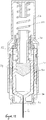
- FIG. 1 is a cross section of an autoinjector in accordance with an embodiment of the invention.
- the autoinjector comprises a drug container 10 holding a drug 12.
- the drug container is closed by a plunger 14 at its rear end.
- the drug container is formed from cyclic olefin copolymer, but it may be formed from any suitable plastics material or may be formed of glass.
- the plunger is formed from a rubber material, such as styrene butadiene rubber.
- a hypodermic needle 16 which is fixed to the drug container 10 using an adhesive, or another suitable fixing mechanism.
- the front end of the needle 16 is embedded in a rubber sock 18, which is coupled to the drug container and completely seals the needle, keeping it sterile.
- the drug container and needle assembly is held within an autoinjector housing 20. Also within the housing 20 is a drive mechanism comprising a stored energy source in the form of a helical spring 22 that is used to drive both insertion of the needle 16 into a patient and to move the plunger 14 within the drug container to expel the drug through the needle 16 into the patient. Any suitable deformable resilient member may be used as the stored energy source.
- An activation mechanism is held within a front portion of the housing 20.
- Retaining arms 24 engage a front portion of the drug container against the action of the spring 22 to prevent activation of the autoinjector.
- a skin sensor component 26 is provided that extends around the retaining arms. When the skin sensor component 26 is moved backward relative to the retaining arms, the front ends of the retaining arms 24 can move into cut-out portions 28 in the skin sensor, releasing the drug container 10 to move forward through the housing 20. Operation of the autoinjector is described in more detail with reference to Figures 9 to 13 .
- a safety cap 30 is provided over the front end of the housing and skin sensor component 26, which engages the rubber sock 18. Removal of the safety cap also results in removal of the rubber sock. Activation of the autoinjector is not possible prior to removal of the safety cap 30.
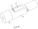
- Figure 1b is a perspective view of the autoinjector of Figure 1a . It can be seen that the autoinjector has a generally round cross-section.
- the housing includes a window 32, through which the contents of the drug container can be viewed.
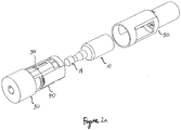
- the autoinjector of Figures 1a and 1b is assembled from three initially separate parts: a front end portion 40, including the safety cap and activation mechanism, the drug container 10, including the plunger 14 and the rubber sock 18 for keeping the needle and drug in a sterile condition, and a rear portion 50 including the drive mechanism.
- Figure 2a is a perspective view of these three separate parts in an unassembled state.
- Figure 2b shows a horizontal section of Figure 2a
- Figure 2c shows a vertical section of Figure 2a .
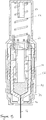
- Figure 3a shows a horizontal section through the rear portion 50, with the spring in a first compressed condition and the locking component in the first position.
- Figure 3b shows a corresponding vertical section through the rear portion.
- the rear portion includes a rear housing 52, which includes window 32.
- the rear housing 52 encases the drive mechanism.
- the drive mechanism comprises a spring 22 in a first deformed condition, in this example a compressed condition.
- the spring 22 is retained in the first compressed condition between the rear surface of the housing 54 and a spring engaging component 56.
- the spring engaging component 56 acts as a pusher in the assembled autoinjector, as described with reference to Figures 9 to 13 .
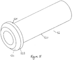
- the spring engaging component 56 is shown in Figure 5 and comprises a cylindrical portion 560 around which spring 22 sits, and a head portion 562 of larger diameter than the cylindrical portion 560.
- the head portion comprises a rear bearing surface 564 against which the front end of spring 22 is pressed, and a front bearing surface 566 which engages a locking component 60.
- the locking component 60 retains the spring engaging component and the spring 22 when in a first position.
- the front bearing surface 566 is chamfered or angled in the region that engages the locking component 60 to allow the spring engaging component 56 to slide past the locking component 60 during drug delivery, as will be described in detail with reference to Figure 11 .
- the locking component 60 bears against the spring engaging component and against the housing 52. Specifically, in a first position the locking component engages two apertures formed in the housing 52. The locking component 60 is thereby locked in the first position against the action of the spring 22, retaining the spring 22 in a first deformed condition.
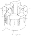
- the locking component 60 is shown separately in Figures 4a and 4b .
- the locking component is in the form of a collar having eight legs extending at their proximal ends from a ring section 600.
- Two resilient legs 610 diametrically opposite each other, have at their distal ends, inner bearing surfaces 615 extending radially inwards for engaging with the front bearing surface 566 of spring engaging component 56.
- a further two legs 620 also have inner bearing surfaces 625 at their distal ends extending radially inwards for engaging with the front bearing surface 566 of spring engaging component 56.
- the inner bearing surfaces 615, 625 are angled to match the angle of the front bearing surface 566. In this embodiment, the inner bearing surfaces are at an angle of about 45 degrees from the longitudinal axis of the spring engaging component.
- Legs 610 also have radially outwardly extending lugs 605 at their distal ends. Lugs 605 engage with apertures 58 in the rear housing 52.
- the further legs 630 are longer than legs 610 and 620 to allow the legs 610 and 620 to deflect freely when further legs 630 are in contact with the drug container. This allows the spring engaging component to pass through the locking component without the legs 610 and 620 of the locking component jamming on the drug container, as shown in Figure 11 .
- the locking component 60, spring engaging component 56 and housing 52 are all formed from a plastics material such as polyoxymethylene (POM) and may be formed by injection moulding.
- POM polyoxymethylene
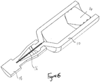
- Figure 6 shows a horizontal section through the drug container 10.
- the drug container 10 is closed by a plunger 14 at its rear end.
- the drug container is formed from cyclic olefin copolymer, but it may be formed from any suitable plastics material or may be formed of glass.
- the plunger is formed from a rubber material, such as styrene butadiene rubber.
- a hypodermic needle 16 is fixed to the drug container 10 using an adhesive, or another suitable fixing mechanism.
- the front end of the needle 16 is embedded in a rubber sock 18, which is coupled to the drug container and completely seals the needle, keeping it sterile.
- FIG. 7 shows a cross section through the front end portion 40.
- Front end portion includes safety cap 30, skin sensor component 26, and front end housing 70.
- Front end housing is configured to receive the drug container 10.
- Resilient arms 24, which are configured to engage the front end of the drug container 10, are formed as part of the front end housing 70.
- Skin sensor component 26 fits around, and is slidable on, the front end housing 70.
- Skin sensor component 26 includes window portions 28, into which the free ends of the resilient arms can be displaced when the skin sensor component is pushed back on front end housing 70.
- Skin sensor component 26 is retained on front end housing by the engagement of lugs on the front end housing (not shown) with a window (not shown) in the skin sensor component.
- Safety cap 30 cap be secured to the skin sensor component using any suitable mechanical fitting, such as a screw fitting or a push fitting.
- the front end housing, skin sensor component and safety cap are all formed from polyester thermoplastic in this example, but may be formed from any suitable plastics material.
- Figure 8 shows a cross section of an autoinjector assembled from the components described with reference to Figures 2 to 7 , in a locked state.
- the filled drug container 10 is received in the front end portion 40.
- the rubber sock 18 is pushed into the socket on the safety cap and received in a snap fitting so that subsequent removal of the safety cap 30 pulls the sock 18 off the needle.
- the rear portion 50 is fitted over the drug container 10 and the front end housing 70 and is coupled and secured to the front end housing by latches 34 shown in Figures 1b , 2a and 2b .
- Latches 34 engage with a front end of windows 32 in the rear portion housing 52.
- Any suitable coupling between the rear portion 50 and the front end portion 40 may be used.
- a latch on the rear portion housing may be used to engage an aperture in the front end portion housing, or a screw fitting may be used.
- Figure 8 shows the autoinjector immediately after the three parts have been assembled to one other but before the autoinjector has been unlocked.
- the locking components 60 are still received in apertures 58 in the rear portion housing 52, retaining the spring 22 in a first deformed condition. In this condition the autoinjector cannot be activated by the skin sensor 26.
- the lugs 605 of the locking component 60 In order to unlock the autoinjector the lugs 605 of the locking component 60 must be pushed inside the rear portion housing 52.
- the locking component legs are resilient so that both lugs 605 must be pushed inwards simultaneously to release the locking component and a specifically designed tool can be used to do this during an automated filling and assembly process. The requirement to push more than one lug simultaneously prevents accidental unlocking before the autoinjector has been assembled.
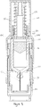
- Figure 9 shows a cross section of the autoinjector after it has been unlocked and with the safety cap 30 removed, but before use.
- the lugs 605 are disengaged from the apertures 58 and the spring 22 has therefore been released from the first deformed condition and has expanded.
- the spring is only allowed to expand a small amount and is retained in a second deformed condition by the abutment of the locking component 60 against the drug container 10.
- the lugs 635 on the locking component abut the rear end of the drug container 10.
- the drug container is prevented from forward movement by the resilient arms 24, which engage the front end of the drug container.
- the resilient arms are fixed relative to the rear portion housing 52 by the latches 34 engaging the windows 32, as shown in Figure 1b . In this second deformed condition the spring 22 still stores enough energy for the needle insertion and drug ejection operations.
- Figures 10 to 13 show cross sections of the autoinjector at various stages during its use.
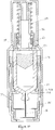
- Figure 10 shows the autoinjector with the skin sensor component pushed back, as it would be when pressed against a patient's skin.
- the skin sensor component 26 is moved rearward until the windows 28 in the skin sensor component align with the ends of the resilient arms 24. At this point the spring 22 is still in the second deformed condition.
- the force exerted by the spring 22 on the drug container 10 pushes the resilient arms outward into the windows 28 allowing the drug container 10 to move forward through the front end housing 70. This is shown in Figure 11 .
- the locking component is also moved forward into a region of the rear portion housing of increased diameter. This allows the legs of the locking component 60 to flex outwardly and the spring engaging component 56 to disengage from and move through the locking component 60.
- the spring engaging component then contacts the plunger 14 and acts as a pusher to drive both the drug container forward to insert the needle into a patient and to move the plunger 14 through drug container 10 to expel the drug through the needle 16.
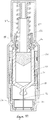
- Figure 12 shows the autoinjector with drug container 10 in its most forward position, with the needle 16 extending beyond the front end of the skin sensor component 26 into a patient. Further forward movement of the drug container is prevented by the front end housing 70 abutting the front end of the drug container.
- the plunger 14 is then moved by the force of the expanding spring 22 through the drug container 10 to expel the drug 12 through the needle 16.
- Figure 13 shows the plunger 14 at the front end of the drug container 10 with the drug delivery completed.
- the spring 22 is then in its most extended position.
- Variations to the described embodiment are of course possible, such as the incorporation known elements such as additional needle safety mechanisms and different arrangements for attaching the needle to the drug container. It is also possible to use a differently shaped locking component or a plurality of separate locking components, for example.
- the locking components may be removed from the autoinjector in an unlocking operation or may be broken in an unlocking operation, or portions of the locking components may be rotated relative to one another or their relative states otherwise altered.
- the invention provides a drive mechanism that can be assembled at a first location and delivered in a locked condition to a second location where a drug filling operation is carried out.
- the drive mechanism can then be assembled to other components to form an autoinjector and the drive mechanism simply unlocked following assembly but prior to delivery to end users.
- the invention is particularly advantageous for autoinjectors with front end activation, using a skin sensor or equivalent.
Landscapes
- Health & Medical Sciences (AREA)
- Vascular Medicine (AREA)
- Engineering & Computer Science (AREA)
- Anesthesiology (AREA)
- Biomedical Technology (AREA)
- Heart & Thoracic Surgery (AREA)
- Hematology (AREA)
- Life Sciences & Earth Sciences (AREA)
- Animal Behavior & Ethology (AREA)
- General Health & Medical Sciences (AREA)
- Public Health (AREA)
- Veterinary Medicine (AREA)
- Infusion, Injection, And Reservoir Apparatuses (AREA)
Claims (15)
- Autoinjektoranordnung, die einen Antriebsmechanismus und einen Arzneimittel enthaltenden Teil aufweist, wobei der Antriebsmechanismus aufweist:ein Gehäuse;ein Antriebsmittel, das mit dem Gehäuse zusammengefügt ist oder Teil davon bildet, wobei das Antriebsmittel ein federndes Element aufweist;ein Haltemittel, das mit dem Gehäuse zusammengefügt ist oder Teil davon bildet, wobei das Haltemittel in einer ersten Stellung mit dem Antriebsmittel in Eingriff ist, um das federnde Element in einem ersten verformten Zustand zu halten, und das Antriebsmittel auslöst, wenn es auf eine zweite Stellung bewegt wird; undein Kupplungsmittel zum Zusammenfügen mit dem Arzneimittel enthaltenden Teil,wobei der Arzneimittel enthaltende Teil so gestaltet ist, dass er das Antriebsmittel in einem zweiten verformten Zustand hält, wenn das Haltemittel auf die zweite Stellung bewegt wird, wobei das Antriebsmittel im zweiten verformten Zustand ausreichend potentielle Energie zum Antreiben des Autoinjektors speichert, und ferner einen Auslösemechanismus aufweist, der gestaltet ist zum Auslösen des Antriebsmechanismus aus dem zweiten verformten Zustand, wenn der Autoinjektor verwendet werden soll.
- Autoinjektor nach Anspruch 1, wobei das Haltemittel eine Sicherungskomponente ist, wobei die Sicherungskomponente in der ersten Stellung mit einer oder mehr Öffnungen oder Rastflächen am Gehäuse in Eingriff ist.
- Autoinjektor nach Anspruch 2, wobei die Sicherungskomponente in der zweiten Stellung außer Eingriff mit den einen oder mehr Öffnungen oder Rastflächen an dem Gehäuse ist.
- Autoinjektor nach Anspruch 2 oder 3, wobei die Sicherungskomponente in der ersten Stellung beansprucht ist.
- Autoinjektor nach einem der vorhergehenden Ansprüche, wobei das Antriebsmittel eine Federeingriffskomponente aufweist, wobei die Federeingriffskomponente in der ersten Stellung mit dem federnden Element und dem Haltemittel zusammengefügt ist und wobei die Federeingriffskomponente eine erste Lagerfläche hat und die Sicherungskomponente eine zweite Lagerfläche hat, wobei in der ersten Stellung die erste Lagerfläche mit der zweiten Lagerfläche in Eingriff ist.
- Autoinjektor nach Anspruch 5, der ferner einen Arzneimittelbehälter, der ein zu verabreichendes Arzneimittel enthält, und einen Kolben aufweist, wobei die Federeingriffskomponente eine Schiebespindel bildet, die gestaltet ist, um während der Betätigung des Autoinjektors mit dem Kolben in Eingriff zu sein.
- Autoinjektor nach einem der vorhergehenden Ansprüche, wobei das Haltemittel mit mehreren Öffnungen im Gehäuse in Eingriff kommt.
- Autoinjektor nach einem der vorhergehenden Ansprüche, wobei das Haltemittel mit dem Kupplungsmittel verbunden ist, so dass das Haltemittel sich nicht in die zweite Stellung bewegen kann, wenn das Kupplungsmittel nicht mit einem Arzneimittel enthaltenden Teil in Eingriff ist.
- Autoinjektor nach einem der vorhergehenden Ansprüche, wobei das Kupplungsmittel eine an dem Gehäuse bereitgestellte Rastklinke oder Öffnung ist.
- Autoinjektor nach einem der vorhergehenden Ansprüche, wobei der Auslösemechanismus einen beweglichen Hautsensor aufweist, der so gestaltet ist, dass der Hautsensor sich bei Aufdrücken des Hautsensors auf einen Injektionsort bewegt, um das Antriebsmittel aus dem zweiten verformten Zustand auszulösen.
- Verfahren zum Zusammensetzen eines Autoinjektors, das die folgenden Schritte aufweist:Zusammensetzen eines Antriebsmechanismus, der ein mit Energie beaufschlagtes federndes Antriebselement in einem ersten gehaltenen Zustand enthält;Zusammensetzen des Antriebsmechanismus mit einem Arzneimittel enthaltenden Teil; undAuslösen des mit Energie beaufschlagten federnden Antriebselements in einen zweiten gehaltenen Zustand, so dass es anschließend aus dem zweiten gehaltenen Zustand ausgelöst werden kann, um ein Antriebsmittel zur Verabreichung eines Medikaments bereitzustellen, wenn der Autoinjektor benutzt werden soll.
- Verfahren nach Anspruch 11, wobei:der Schritt des Zusammensetzens eines Antriebsmechanismus das Einsetzen oder Bilden eines federnden Antriebselements in einen/m ersten Gehäuseteil und das Halten des federnden Antriebselements in einem ersten verformten Zustand in dem Gehäuse unter Verwendung eines mit dem Antriebselement zusammengefügten Haltemittels in einer ersten Stellung aufweist;der Schritt des Zusammensetzens des Antriebsmechanismus mit einem Arzneimittel enthaltenden Teil das Zusammenfügen des ersten Gehäuseteils mit einem zweiten Gehäuseteil aufweist, wobei der zweite Gehäuseteil ein durch den Autoinjektor zu verabreichendes Arzneimittel enthält; undder Schritt des Auslösens das Bewegen des Haltemittels auf eine zweite Stellung zum Auslösen des federnden Antriebselements in einen zweiten verformten Zustand aufweist, wobei der zweite Gehäuseteil das federnde Antriebselement im zweiten verformten Zustand hält und wobei im zweiten verformten Zustand das Antriebselement ausreichend potentielle Energie zum Einführen der Nadel und/oder zum Ausstoßen des Arzneimittels, wenn der Autoinjektor benutzt werden soll, speichert.
- Verfahren nach Anspruch 12, wobei der Schritt des Bewegens des Haltemittels als eine Folge des Zusammenfügungsschritts durchgeführt wird.
- Verfahren nach Anspruch 12, wobei der Schritt des Bewegens des Haltemittels das Drücken eines Teils oder von Teilen des Haltemittels durch eine oder mehr Öffnungen in dem ersten Gehäuseteil aufweist.
- Bausatz zum Zusammensetzen zu einem Autoinjektor, wobei der Bausatz Folgendes aufweist: einen Antriebsmechanismus und einen Arzneimittel enthaltenden Teil, wobei der Antriebsmechanismus Folgendes aufweist:ein Gehäuse;ein Antriebsmittel, das mit dem Gehäuse zusammengefügt ist oder Teil davon bildet, wobei das Antriebsmittel ein federndes Element aufweist;ein Haltemittel, das mit dem Gehäuse zusammengefügt ist oder Teil davon bildet, wobei das Haltemittel in einer ersten Stellung mit dem Antriebsmittel in Eingriff ist, um das federnde Element in einem ersten verformten Zustand zu halten, und das Antriebsmittel auslöst, wenn es auf eine zweite Stellung bewegt wird; undein Kupplungsmittel zum Zusammenfügen mit einem Arzneimittel enthaltenden Teil,wobei, wenn das Antriebsmittel mit dem Arzneimittel enthaltenden Teil zusammengefügt ist, der Arzneimittel enthaltende Teil das Antriebsmittel in einem zweiten verformten Zustand hält, wenn das Haltemittel auf die zweite Stellung bewegt wird, wobei das Antriebsmittel im zweiten verformten Zustand ausreichend potentielle Energie zum Antreiben des Autoinjektors speichert und von einem Benutzer aus dem zweiten verformten Zustand auslösbar ist, wenn der Autoinjektor verwendet werden soll.
Applications Claiming Priority (2)
| Application Number | Priority Date | Filing Date | Title |
|---|---|---|---|
| GBGB1020472.5A GB201020472D0 (en) | 2010-12-02 | 2010-12-02 | A drive assembly for an autoinjector |
| PCT/GB2011/052375 WO2012073032A1 (en) | 2010-12-02 | 2011-12-01 | A drive assembly for an autoinjector and a method of assembling an autoinjector |
Publications (3)
| Publication Number | Publication Date |
|---|---|
| EP2646085A1 EP2646085A1 (de) | 2013-10-09 |
| EP2646085B1 true EP2646085B1 (de) | 2019-07-10 |
| EP2646085B8 EP2646085B8 (de) | 2019-08-21 |
Family
ID=43531384
Family Applications (1)
| Application Number | Title | Priority Date | Filing Date |
|---|---|---|---|
| EP11793857.1A Revoked EP2646085B8 (de) | 2010-12-02 | 2011-12-01 | Antriebsanordnung für einen autoinjektor und verfahren zur montage eines autoinjektors |
Country Status (6)
| Country | Link |
|---|---|
| US (1) | US10166335B2 (de) |
| EP (1) | EP2646085B8 (de) |
| JP (1) | JP6151184B2 (de) |
| CN (1) | CN103328024B (de) |
| GB (1) | GB201020472D0 (de) |
| WO (1) | WO2012073032A1 (de) |
Families Citing this family (118)
| Publication number | Priority date | Publication date | Assignee | Title |
|---|---|---|---|---|
| AUPQ867900A0 (en) | 2000-07-10 | 2000-08-03 | Medrad, Inc. | Medical injector system |
| US7666169B2 (en) | 2003-11-25 | 2010-02-23 | Medrad, Inc. | Syringe and syringe plungers for use with medical injectors |
| USD1031029S1 (en) | 2003-11-25 | 2024-06-11 | Bayer Healthcare Llc | Syringe plunger |
| US8926569B2 (en) | 2006-03-15 | 2015-01-06 | Bayer Medical Care Inc. | Plunger covers and plungers for use in syringes and methods of fabricating plunger covers and plungers for use in syringes |
| USD942005S1 (en) | 2007-03-14 | 2022-01-25 | Bayer Healthcare Llc | Orange syringe plunger cover |
| USD847985S1 (en) | 2007-03-14 | 2019-05-07 | Bayer Healthcare Llc | Syringe plunger cover |
| CN101868273B (zh) | 2007-10-02 | 2014-10-15 | 莱蒙德尔有限公司 | 外部药泵 |
| US9974904B2 (en) | 2008-05-20 | 2018-05-22 | Avant Medical Corp. | Autoinjector system |
| US8052645B2 (en) | 2008-07-23 | 2011-11-08 | Avant Medical Corp. | System and method for an injection using a syringe needle |
| US8177749B2 (en) | 2008-05-20 | 2012-05-15 | Avant Medical Corp. | Cassette for a hidden injection needle |
| US7959598B2 (en) | 2008-08-20 | 2011-06-14 | Asante Solutions, Inc. | Infusion pump systems and methods |
| GB201020472D0 (en) | 2010-12-02 | 2011-01-19 | Oval Medical Technologies Ltd | A drive assembly for an autoinjector |
| US9084849B2 (en) | 2011-01-26 | 2015-07-21 | Kaleo, Inc. | Medicament delivery devices for administration of a medicament within a prefilled syringe |
| LT2699293T (lt) | 2011-04-20 | 2019-04-25 | Amgen Inc. | Automatinio purškimo prietaisas |
| EP2601992A1 (de) | 2011-12-08 | 2013-06-12 | Sanofi-Aventis Deutschland GmbH | Spritzenträger |
| HUE067982T2 (hu) | 2012-03-30 | 2024-12-28 | Insulet Corp | Folyadékadagoló készülék transzkután beviteli eszközzel, behelyezõ mechanizmussal és vércukor monitorozással |
| USD898908S1 (en) | 2012-04-20 | 2020-10-13 | Amgen Inc. | Pharmaceutical product cassette for an injection device |
| USD808010S1 (en) * | 2012-04-20 | 2018-01-16 | Amgen Inc. | Injection device |
| US9522235B2 (en) | 2012-05-22 | 2016-12-20 | Kaleo, Inc. | Devices and methods for delivering medicaments from a multi-chamber container |
| US9174003B2 (en) | 2012-09-28 | 2015-11-03 | Bayer Medical Care Inc. | Quick release plunger |
| CA2903484C (en) | 2013-03-13 | 2019-01-08 | Antares Pharma, Inc. | Push button safety injector |
| EP2777684A1 (de) | 2013-03-14 | 2014-09-17 | Sanofi-Aventis Deutschland GmbH | Medikamentenbehälterträger und -adapter |
| US10492990B2 (en) | 2013-03-15 | 2019-12-03 | Amgen Inc. | Drug cassette, autoinjector, and autoinjector system |
| US10092703B2 (en) | 2013-03-15 | 2018-10-09 | Amgen Inc. | Drug cassette, autoinjector, and autoinjector system |
| US10322240B2 (en) | 2013-03-25 | 2019-06-18 | Shl Medical Ag | Power pack lock |
| WO2014172467A1 (en) | 2013-04-16 | 2014-10-23 | Smartloop Llc | Discretionary insulin delivery systems and methods |
| EP2823841A1 (de) | 2013-07-09 | 2015-01-14 | Sanofi-Aventis Deutschland GmbH | Autoinjektor |
| US9561324B2 (en) | 2013-07-19 | 2017-02-07 | Bigfoot Biomedical, Inc. | Infusion pump system and method |
| TW201519886A (zh) | 2013-08-29 | 2015-06-01 | Sanofi Sa | 用於藥物容器的帽蓋 |
| WO2015037545A1 (ja) * | 2013-09-13 | 2015-03-19 | テルモ株式会社 | 液体投与具 |
| US10195360B2 (en) * | 2013-11-15 | 2019-02-05 | Sanofi-Aventis Deutschland Gmbh | Member and assembly for a drug delivery device, drug delivery device and use of a member |
| EP2878319A1 (de) * | 2013-11-28 | 2015-06-03 | Sanofi-Aventis Deutschland GmbH | Muffenabzieher |
| EP2878322A1 (de) * | 2013-11-28 | 2015-06-03 | Sanofi-Aventis Deutschland GmbH | Nadelkappenabzieher und Arzneimittelabgabevorrichtung |
| US10625026B2 (en) | 2014-01-21 | 2020-04-21 | Parenteral Technologies, Llc | Force actuated injection device |
| AU2015209535B2 (en) * | 2014-01-21 | 2017-06-01 | Parenteral Technologies, Llc | Force actuated injection device |
| CN106232170B (zh) | 2014-02-17 | 2022-07-29 | 诺博国际公司 | 检测和防止湿式注射的系统和方法 |
| CN106102806B (zh) | 2014-03-19 | 2019-12-17 | 拜耳医药保健有限公司 | 用于将针筒接合到注射器的系统 |
| EP2923716A1 (de) * | 2014-03-28 | 2015-09-30 | Sanofi-Aventis Deutschland GmbH | Kappe mit Hüllenentfernungsmechanismus |
| EP2923714A1 (de) | 2014-03-28 | 2015-09-30 | Sanofi-Aventis Deutschland GmbH | Durch hautkontakt ausgelöste Autoinjektor |
| EP2944340A1 (de) * | 2014-05-12 | 2015-11-18 | Sanofi | Aktivierungsmechanismus für eine Medikamentenabgabevorrichtung und Medikamentenabgabevorrichtung |
| EP2944341A1 (de) * | 2014-05-12 | 2015-11-18 | Sanofi | Aktivierungsmechanismus für eine Medikamentenabgabevorrichtung und Medikamentenabgabevorrichtung |
| US20170103186A1 (en) * | 2014-06-03 | 2017-04-13 | Amgen Inc. | Systems and methods for supporting patient use of a drug delivery device |
| US9415176B1 (en) | 2015-01-22 | 2016-08-16 | West Pharmaceutical Services, Inc. | Autoinjector having an end-of-dose visual indicator |
| US10695495B2 (en) | 2015-03-24 | 2020-06-30 | Kaleo, Inc. | Devices and methods for delivering a lyophilized medicament |
| JP6567687B2 (ja) * | 2015-04-24 | 2019-08-28 | エス・ハー・エル・メディカル・アクチェンゲゼルシャフトShl Medical Ag | 自動注射器の駆動機構 |
| TW201705994A (zh) | 2015-06-03 | 2017-02-16 | 賽諾菲阿凡提斯德意志有限公司 | 自動注射器及組裝方法 |
| TW201700117A (zh) * | 2015-06-03 | 2017-01-01 | 賽諾菲阿凡提斯德意志有限公司 | 用於自動注射器的注射筒托架和組裝方法 |
| WO2017004345A1 (en) | 2015-06-30 | 2017-01-05 | Kaleo, Inc. | Auto-injectors for administration of a medicament within a prefilled syringe |
| US10576207B2 (en) | 2015-10-09 | 2020-03-03 | West Pharma. Services IL, Ltd. | Angled syringe patch injector |
| US10279123B2 (en) * | 2015-10-01 | 2019-05-07 | Noble International, Inc. | Microcartridge |
| CN113648488B (zh) | 2015-10-09 | 2024-03-29 | 西医药服务以色列分公司 | 至预填充的流体储存器的弯曲流体路径附加装置 |
| US9480797B1 (en) | 2015-10-28 | 2016-11-01 | Bayer Healthcare Llc | System and method for syringe plunger engagement with an injector |
| WO2017076925A1 (en) | 2015-11-05 | 2017-05-11 | Sanofi-Aventis Deutschland Gmbh | Cartridge carrier assembly |
| EP3374905A1 (de) | 2016-01-13 | 2018-09-19 | Bigfoot Biomedical, Inc. | Benutzerschnittstelle für diabetesmanagementsystem |
| HK1256995A1 (zh) | 2016-01-14 | 2019-10-11 | Bigfoot Biomedical, Inc. | 药物输送设备、系统和方法中的阻塞解决方案 |
| EP4545005A3 (de) | 2016-01-14 | 2025-07-02 | Insulet Corporation | Einstellung der insulinabgaberaten |
| US11311674B2 (en) | 2016-01-21 | 2022-04-26 | West Pharma. Services IL, Ltd. | Medicament delivery device comprising a visual indicator |
| WO2017127215A1 (en) | 2016-01-21 | 2017-07-27 | Medimop Medical Projects Ltd. | Needle insertion and retraction mechanism |
| CN111544704B (zh) | 2016-01-21 | 2022-06-03 | 西医药服务以色列有限公司 | 自动注射器中的力牵制 |
| WO2017161076A1 (en) | 2016-03-16 | 2017-09-21 | Medimop Medical Projects Ltd. | Staged telescopic screw assembly having different visual indicators |
| US12383166B2 (en) | 2016-05-23 | 2025-08-12 | Insulet Corporation | Insulin delivery system and methods with risk-based set points |
| EP3646905B1 (de) | 2016-05-26 | 2021-06-23 | Insulet Corporation | Vorrichtung zur abgabe von arzneimitteln in einzeldosis |
| CN113577438B (zh) | 2016-08-01 | 2023-05-23 | 西医药服务以色列有限公司 | 部分门关闭防止弹簧 |
| CN109562229B (zh) | 2016-08-01 | 2021-07-13 | 西医药服务以色列有限公司 | 抗旋转药筒销 |
| US10363372B2 (en) | 2016-08-12 | 2019-07-30 | Insulet Corporation | Plunger for drug delivery device |
| EP3496789A1 (de) | 2016-08-14 | 2019-06-19 | Insulet Corporation | Automatische wirkstofffreisetzungsvorrichtung mit auslösemechanismus |
| WO2018067645A1 (en) | 2016-10-07 | 2018-04-12 | Insulet Corporation | Multi-stage delivery system |
| US10780217B2 (en) | 2016-11-10 | 2020-09-22 | Insulet Corporation | Ratchet drive for on body delivery system |
| AU2017376111B2 (en) | 2016-12-12 | 2023-02-02 | Bigfoot Biomedical, Inc. | Alarms and alerts for medication delivery devices and related systems and methods |
| CA3046228A1 (en) | 2016-12-23 | 2018-06-28 | Kaleo, Inc. | Medicament delivery device and methods for delivering drugs to infants and children |
| DK3565619T3 (da) | 2017-01-06 | 2023-10-30 | Bayer Healthcare Llc | Sprøjtestempel med dynamisk forsegling |
| US10881793B2 (en) | 2017-01-13 | 2021-01-05 | Bigfoot Biomedical, Inc. | System and method for adjusting insulin delivery |
| US10583250B2 (en) | 2017-01-13 | 2020-03-10 | Bigfoot Biomedical, Inc. | System and method for adjusting insulin delivery |
| US10758675B2 (en) | 2017-01-13 | 2020-09-01 | Bigfoot Biomedical, Inc. | System and method for adjusting insulin delivery |
| EP4708310A3 (de) | 2017-01-13 | 2026-05-06 | Insulet Corporation | Insulinverabreichungsverfahren, -systeme und -vorrichtungen |
| US10500334B2 (en) | 2017-01-13 | 2019-12-10 | Bigfoot Biomedical, Inc. | System and method for adjusting insulin delivery |
| EP4708311A3 (de) | 2017-01-13 | 2026-05-20 | Insulet Corporation | Insulinverabreichungsverfahren, -systeme und -vorrichtungen |
| US10603440B2 (en) | 2017-01-19 | 2020-03-31 | Insulet Corporation | Cartridge hold-up volume reduction |
| US10695485B2 (en) | 2017-03-07 | 2020-06-30 | Insulet Corporation | Very high volume user filled drug delivery device |
| WO2018206583A1 (en) * | 2017-05-09 | 2018-11-15 | Shl Medical Ag | Transport lock assembly, and a medicament delivery device comprising the transport lock assembly |
| WO2018222521A1 (en) | 2017-05-30 | 2018-12-06 | West Pharma. Services IL, Ltd. | Modular drive train for wearable injector |
| WO2019011689A1 (en) * | 2017-07-12 | 2019-01-17 | Shl Medical Ag | TRANSPORT ASSEMBLY FOR DRUG DELIVERY DEVICE AND DRUG DELIVERY DEVICE COMPRISING SAME |
| US12653426B2 (en) | 2017-07-13 | 2026-06-16 | Bigfoot Biomedical, Inc. | Multi-scale display of blood glucose information |
| EP3662161B1 (de) | 2017-08-03 | 2024-05-01 | Insulet Corporation | Mikrokolbenpumpe |
| US10973978B2 (en) | 2017-08-03 | 2021-04-13 | Insulet Corporation | Fluid flow regulation arrangements for drug delivery devices |
| US11786668B2 (en) | 2017-09-25 | 2023-10-17 | Insulet Corporation | Drug delivery devices, systems, and methods with force transfer elements |
| EP3740266A4 (de) | 2018-01-19 | 2021-10-13 | Birya Biotech, Inc. | Werkzeug zur wartung eines automatischen injektors |
| ES2939249T3 (es) | 2018-02-27 | 2023-04-20 | Bayer Healthcare Llc | Mecanismo de acoplamiento de émbolo de jeringa |
| USD928199S1 (en) | 2018-04-02 | 2021-08-17 | Bigfoot Biomedical, Inc. | Medication delivery device with icons |
| US12562251B1 (en) | 2018-05-09 | 2026-02-24 | Bigfoot Biomedical, Inc. | Computing architecture for assuring the provenance of medication therapy related parameters, and related systems, methods and devices |
| US10835685B2 (en) * | 2018-05-30 | 2020-11-17 | Amgen Inc. | Thermal spring release mechanism for a drug delivery device |
| US10874803B2 (en) | 2018-05-31 | 2020-12-29 | Insulet Corporation | Drug cartridge with drive system |
| US11229736B2 (en) | 2018-06-06 | 2022-01-25 | Insulet Corporation | Linear shuttle pump for drug delivery |
| JP7262573B2 (ja) | 2018-10-05 | 2023-04-21 | フィリップス - メディサイズ エー/エス | 自動剛性針シールド除去装置を備える自動注射器 |
| US11446435B2 (en) | 2018-11-28 | 2022-09-20 | Insulet Corporation | Drug delivery shuttle pump system and valve assembly |
| WO2020140040A1 (en) | 2018-12-29 | 2020-07-02 | Kaleo, Inc. | Devices and methods for delivery of substances within a prefilled syringe |
| USD920343S1 (en) | 2019-01-09 | 2021-05-25 | Bigfoot Biomedical, Inc. | Display screen or portion thereof with graphical user interface associated with insulin delivery |
| US12643950B1 (en) * | 2019-02-07 | 2026-06-02 | Takeda Pharmaceutical Company Limited | Autoinjector comprising high concentration formulation of vedolizumab |
| IL323403B1 (en) | 2019-08-09 | 2026-07-01 | Kaleo Inc | Devices and methods for transferring materials into a prefilled syringe |
| US11369735B2 (en) | 2019-11-05 | 2022-06-28 | Insulet Corporation | Component positioning of a linear shuttle pump |
| CR20220648A (es) | 2020-06-18 | 2023-07-03 | Bayer Healthcare Llc | Sistema y método para el acoplamiento del émbolo de la jeringa con un inyector |
| CN112076364B (zh) * | 2020-10-16 | 2024-05-17 | 山东威高普瑞医药包装有限公司 | 一种自动注射器 |
| JP7665028B2 (ja) | 2020-12-18 | 2025-04-18 | インスレット コーポレイション | 薬物送達デバイスによる将来の日付および時刻における薬物ボーラス送達の、コンピューティングデバイスを用いたスケジュール設定 |
| EP4274640A1 (de) | 2021-01-08 | 2023-11-15 | Insulet Corporation | Einzelbetätigte präzisionsdosierungszwischenpumpkammer |
| US12440617B2 (en) | 2021-01-11 | 2025-10-14 | Insulet Corporation | Linear activated drug dosing pump system |
| US12268847B1 (en) | 2021-02-10 | 2025-04-08 | Kaleo, Inc. | Devices and methods for delivery of substances within a medicament container |
| US12616790B2 (en) | 2021-03-12 | 2026-05-05 | Insulet Corporation | Pumping mechanism with wire-pulled plunger |
| CN117396242A (zh) | 2021-05-21 | 2024-01-12 | 英赛罗公司 | 用于可穿戴式药物输送装置的紧凑型正排量泵 |
| WO2022251642A1 (en) | 2021-05-28 | 2022-12-01 | Insulet Corporation | Spring-based status sensors |
| US12514980B2 (en) | 2021-06-30 | 2026-01-06 | Insulet Corporation | Adjustment of medicament delivery by a medicament delivery device based on menstrual cycle phase |
| US12521486B2 (en) | 2021-07-16 | 2026-01-13 | Insulet Corporation | Method for modification of insulin delivery during pregnancy in automatic insulin delivery systems |
| WO2023003793A1 (en) | 2021-07-19 | 2023-01-26 | Becton, Dickinson And Company | Needle shield remover assembly for wearable injector |
| US12653949B2 (en) | 2021-07-29 | 2026-06-16 | Insulet Corporation | Adaptation of medicament delivery in response to user stress load |
| EP4419161A1 (de) | 2021-10-18 | 2024-08-28 | Insulet Corporation | Antriebsmechanismus für verdrängerpumpen |
| EP4511843A1 (de) | 2022-04-21 | 2025-02-26 | Insulet Corporation | Insulinanpassung und sicherheitsüberwachung für krankentagmanagement |
| KR20250129777A (ko) | 2023-01-06 | 2025-08-29 | 인슐렛 코포레이션 | 후속 자동 안전 제약 완화를 갖는 자동으로 또는 수동으로 개시되는 음식 볼러스 전달 |
| KR102694745B1 (ko) * | 2023-04-18 | 2024-08-14 | 주식회사 비에스엘 | 청각 피드백을 제공하는 자동 약물 주입 장치 |
| CN117398234B (zh) * | 2023-12-14 | 2024-03-12 | 北京茗视光眼科医院管理有限公司 | 一种白内障穿刺器 |
Citations (15)
| Publication number | Priority date | Publication date | Assignee | Title |
|---|---|---|---|---|
| DD245817A5 (de) | 1985-05-20 | 1987-05-20 | �������@���������@���Kk�� | Automatische injektionsvorrichtung |
| WO1999020327A2 (en) | 1997-10-21 | 1999-04-29 | I-Flow Corporation | Spring-actuated infusion syringe |
| US6793646B1 (en) | 1999-04-16 | 2004-09-21 | Becton Dickinson And Company | Pen style injector with automated substance combining feature |
| US20040225262A1 (en) | 2003-05-06 | 2004-11-11 | Fathallah Marwan A. | Autoinjector with extendable needle protector shroud |
| US20050222539A1 (en) | 2004-03-30 | 2005-10-06 | Pediamed Pharmaceuticals, Inc. | Automatic injection device |
| EP1759728A1 (de) | 2005-09-05 | 2007-03-07 | JCR Pharmaceuticals Co., Ltd. | Injektionsvorrichtung für Zweikammerampullen |
| EP1790366A1 (de) | 2005-11-29 | 2007-05-30 | JCR Pharmaceuticals Co., Ltd. | Injektionsvorrichtung |
| WO2007083115A1 (en) | 2006-01-23 | 2007-07-26 | The Medical House Plc | Improved autoinjector supporting the syringe at the front |
| WO2008005315A2 (en) | 2006-06-30 | 2008-01-10 | Abbott Biotechnology Ltd. | Automatic injection device |
| US20080262438A1 (en) | 2007-03-22 | 2008-10-23 | Markus Bollenbach | Injection device with a time-constant delivery signal |
| US20090118669A1 (en) | 2004-11-24 | 2009-05-07 | Antonio Bendek | Automatic Reconstitution Injector Device |
| WO2010033808A2 (en) | 2008-09-18 | 2010-03-25 | Becton, Dickinson And Company | Medical injector with post-autoreconstitution dose setting and autoplunger drive |
| DE102008037310A1 (de) | 2008-08-11 | 2010-07-29 | Tecpharma Licensing Ag | Automatische Injektionsvorrichtung für die Verabreichung einer festen Dosis |
| EP2010252B1 (de) | 2006-04-12 | 2010-12-22 | TecPharma Licensing AG | Injektionsvorrichtung mit Spannfeder und Spannelement |
| WO2012073032A1 (en) | 2010-12-02 | 2012-06-07 | Oval Medical Technologies Limited | A drive assembly for an autoinjector and a method of assembling an autoinjector |
Family Cites Families (19)
| Publication number | Priority date | Publication date | Assignee | Title |
|---|---|---|---|---|
| US6547764B2 (en) * | 2000-05-31 | 2003-04-15 | Novo Nordisk A/S | Double pointed injection needle |
| SE518981C2 (sv) * | 2000-12-14 | 2002-12-17 | Shl Medical Ab | Autoinjektor |
| US20030105430A1 (en) * | 2001-11-30 | 2003-06-05 | Elan Pharma International Limited Wil House | Automatic injector |
| DK1448256T3 (da) * | 2001-11-30 | 2006-05-29 | Novo Nordisk As | Sikkerhedsnålkonstruktion |
| GB0211294D0 (en) | 2002-05-17 | 2002-06-26 | Owen Mumford Ltd | Improvements relating to injection devices |
| AU2003275893B2 (en) | 2002-11-25 | 2008-11-13 | Tecpharma Licensing Ag | Device for automatically injecting an active agent |
| DE10342059B4 (de) * | 2003-09-11 | 2007-03-01 | Tecpharma Licensing Ag | Verabreichungsvorrichtung mit Einstech- und Ausschütteinrichtung |
| GB0406458D0 (en) * | 2003-10-09 | 2004-04-28 | Liversidge Barry P | Safety medical needle assemblies |
| GB2410188B (en) * | 2004-01-23 | 2006-01-25 | Medical House Plc | Injection device |
| AU2005205966B2 (en) * | 2004-01-23 | 2010-08-05 | Shl Medical Ag | Injection device |
| US8048035B2 (en) * | 2004-08-06 | 2011-11-01 | Meridian Medical Technologies, Inc. | Automatic injector with needle cover |
| US7449012B2 (en) | 2004-08-06 | 2008-11-11 | Meridian Medical Technologies, Inc. | Automatic injector |
| JP2008543500A (ja) * | 2005-06-21 | 2008-12-04 | イーライ リリー アンド カンパニー | 医薬品注射用の器具及び方法 |
| FR2899482A1 (fr) | 2006-04-11 | 2007-10-12 | Becton Dickinson France Soc Pa | Dispositif d'injection automatique |
| EP2259817A1 (de) * | 2008-02-22 | 2010-12-15 | Vakos XT A.S. | Automatisches injektionsgerät mit drei kammern |
| ES2548447T3 (es) * | 2008-03-10 | 2015-10-16 | Antares Pharma, Inc. | Dispositivo de seguridad para inyector |
| ES2729650T3 (es) * | 2008-03-13 | 2019-11-05 | Becton Dickinson Co | Conjunto de aguja de seguridad |
| US8979807B2 (en) | 2008-09-29 | 2015-03-17 | Becton Dickinson France | Automatic injection device with audible indicator of completed injection |
| US8663174B2 (en) * | 2009-11-13 | 2014-03-04 | Becton, Dickinson And Company | Hub assembly having a hidden needle for a drug delivery pen |
-
2010
- 2010-12-02 GB GBGB1020472.5A patent/GB201020472D0/en not_active Ceased
-
2011
- 2011-12-01 CN CN201180064512.9A patent/CN103328024B/zh not_active Expired - Fee Related
- 2011-12-01 WO PCT/GB2011/052375 patent/WO2012073032A1/en not_active Ceased
- 2011-12-01 EP EP11793857.1A patent/EP2646085B8/de not_active Revoked
- 2011-12-01 US US13/989,556 patent/US10166335B2/en active Active
- 2011-12-01 JP JP2013541427A patent/JP6151184B2/ja active Active
Patent Citations (15)
| Publication number | Priority date | Publication date | Assignee | Title |
|---|---|---|---|---|
| DD245817A5 (de) | 1985-05-20 | 1987-05-20 | �������@���������@���Kk�� | Automatische injektionsvorrichtung |
| WO1999020327A2 (en) | 1997-10-21 | 1999-04-29 | I-Flow Corporation | Spring-actuated infusion syringe |
| US6793646B1 (en) | 1999-04-16 | 2004-09-21 | Becton Dickinson And Company | Pen style injector with automated substance combining feature |
| US20040225262A1 (en) | 2003-05-06 | 2004-11-11 | Fathallah Marwan A. | Autoinjector with extendable needle protector shroud |
| US20050222539A1 (en) | 2004-03-30 | 2005-10-06 | Pediamed Pharmaceuticals, Inc. | Automatic injection device |
| US20090118669A1 (en) | 2004-11-24 | 2009-05-07 | Antonio Bendek | Automatic Reconstitution Injector Device |
| EP1759728A1 (de) | 2005-09-05 | 2007-03-07 | JCR Pharmaceuticals Co., Ltd. | Injektionsvorrichtung für Zweikammerampullen |
| EP1790366A1 (de) | 2005-11-29 | 2007-05-30 | JCR Pharmaceuticals Co., Ltd. | Injektionsvorrichtung |
| WO2007083115A1 (en) | 2006-01-23 | 2007-07-26 | The Medical House Plc | Improved autoinjector supporting the syringe at the front |
| EP2010252B1 (de) | 2006-04-12 | 2010-12-22 | TecPharma Licensing AG | Injektionsvorrichtung mit Spannfeder und Spannelement |
| WO2008005315A2 (en) | 2006-06-30 | 2008-01-10 | Abbott Biotechnology Ltd. | Automatic injection device |
| US20080262438A1 (en) | 2007-03-22 | 2008-10-23 | Markus Bollenbach | Injection device with a time-constant delivery signal |
| DE102008037310A1 (de) | 2008-08-11 | 2010-07-29 | Tecpharma Licensing Ag | Automatische Injektionsvorrichtung für die Verabreichung einer festen Dosis |
| WO2010033808A2 (en) | 2008-09-18 | 2010-03-25 | Becton, Dickinson And Company | Medical injector with post-autoreconstitution dose setting and autoplunger drive |
| WO2012073032A1 (en) | 2010-12-02 | 2012-06-07 | Oval Medical Technologies Limited | A drive assembly for an autoinjector and a method of assembling an autoinjector |
Also Published As
| Publication number | Publication date |
|---|---|
| EP2646085A1 (de) | 2013-10-09 |
| JP2014500089A (ja) | 2014-01-09 |
| US10166335B2 (en) | 2019-01-01 |
| EP2646085B8 (de) | 2019-08-21 |
| JP6151184B2 (ja) | 2017-06-21 |
| US20130317480A1 (en) | 2013-11-28 |
| CN103328024A (zh) | 2013-09-25 |
| GB201020472D0 (en) | 2011-01-19 |
| CN103328024B (zh) | 2016-08-10 |
| WO2012073032A1 (en) | 2012-06-07 |
Similar Documents
| Publication | Publication Date | Title |
|---|---|---|
| US10166335B2 (en) | Drive assembly for an autoinjector and a method of assembling an autoinjector | |
| EP2288398B1 (de) | Automatischer injektionsmechanismus mit vorderstreben | |
| EP2750738B1 (de) | Injektionsvorrichtung | |
| EP3027247B1 (de) | Arzneimittelabgabevorrichtung | |
| CN107735124B (zh) | 注射装置 | |
| US10406288B2 (en) | Delivery mechanism for an autoinjector | |
| CN109069745B (zh) | 注射装置 | |
| JP2021519669A (ja) | メモリ要素を有する自動注入装置 | |
| WO2017178237A1 (en) | Injection device | |
| GB2504128A (en) | Automatic injector with a skin contact element | |
| EP3442621A1 (de) | Injektionsvorrichtung |
Legal Events
| Date | Code | Title | Description |
|---|---|---|---|
| PUAI | Public reference made under article 153(3) epc to a published international application that has entered the european phase |
Free format text: ORIGINAL CODE: 0009012 |
|
| 17P | Request for examination filed |
Effective date: 20130611 |
|
| AK | Designated contracting states |
Kind code of ref document: A1 Designated state(s): AL AT BE BG CH CY CZ DE DK EE ES FI FR GB GR HR HU IE IS IT LI LT LU LV MC MK MT NL NO PL PT RO RS SE SI SK SM TR |
|
| DAX | Request for extension of the european patent (deleted) | ||
| REG | Reference to a national code |
Ref country code: DE Ref legal event code: R079 Ref document number: 602011060383 Country of ref document: DE Free format text: PREVIOUS MAIN CLASS: A61M0005200000 Ipc: A61M0005320000 |
|
| GRAP | Despatch of communication of intention to grant a patent |
Free format text: ORIGINAL CODE: EPIDOSNIGR1 |
|
| STAA | Information on the status of an ep patent application or granted ep patent |
Free format text: STATUS: GRANT OF PATENT IS INTENDED |
|
| RIC1 | Information provided on ipc code assigned before grant |
Ipc: A61M 5/20 20060101ALI20181219BHEP Ipc: A61M 5/32 20060101AFI20181219BHEP |
|
| INTG | Intention to grant announced |
Effective date: 20190121 |
|
| RIN1 | Information on inventor provided before grant (corrected) |
Inventor name: YOUNG, MATTHEW Inventor name: REBER, DOMINIC CHARLES Inventor name: HUANG, CONGYI |
|
| GRAS | Grant fee paid |
Free format text: ORIGINAL CODE: EPIDOSNIGR3 |
|
| GRAA | (expected) grant |
Free format text: ORIGINAL CODE: 0009210 |
|
| STAA | Information on the status of an ep patent application or granted ep patent |
Free format text: STATUS: THE PATENT HAS BEEN GRANTED |
|
| AK | Designated contracting states |
Kind code of ref document: B1 Designated state(s): AL AT BE BG CH CY CZ DE DK EE ES FI FR GB GR HR HU IE IS IT LI LT LU LV MC MK MT NL NO PL PT RO RS SE SI SK SM TR |
|
| REG | Reference to a national code |
Ref country code: GB Ref legal event code: FG4D |
|
| REG | Reference to a national code |
Ref country code: CH Ref legal event code: EP Ref country code: AT Ref legal event code: REF Ref document number: 1152856 Country of ref document: AT Kind code of ref document: T Effective date: 20190715 |
|
| RAP2 | Party data changed (patent owner data changed or rights of a patent transferred) |
Owner name: OVAL MEDICAL TECHNOLOGIES LIMITED |
|
| REG | Reference to a national code |
Ref country code: CH Ref legal event code: PK Free format text: BERICHTIGUNG B8 |
|
| REG | Reference to a national code |
Ref country code: DE Ref legal event code: R096 Ref document number: 602011060383 Country of ref document: DE |
|
| REG | Reference to a national code |
Ref country code: IE Ref legal event code: FG4D |
|
| REG | Reference to a national code |
Ref country code: NL Ref legal event code: MP Effective date: 20190710 |
|
| REG | Reference to a national code |
Ref country code: LT Ref legal event code: MG4D |
|
| REG | Reference to a national code |
Ref country code: AT Ref legal event code: MK05 Ref document number: 1152856 Country of ref document: AT Kind code of ref document: T Effective date: 20190710 |
|
| PG25 | Lapsed in a contracting state [announced via postgrant information from national office to epo] |
Ref country code: NO Free format text: LAPSE BECAUSE OF FAILURE TO SUBMIT A TRANSLATION OF THE DESCRIPTION OR TO PAY THE FEE WITHIN THE PRESCRIBED TIME-LIMIT Effective date: 20191010 Ref country code: BG Free format text: LAPSE BECAUSE OF FAILURE TO SUBMIT A TRANSLATION OF THE DESCRIPTION OR TO PAY THE FEE WITHIN THE PRESCRIBED TIME-LIMIT Effective date: 20191010 Ref country code: NL Free format text: LAPSE BECAUSE OF FAILURE TO SUBMIT A TRANSLATION OF THE DESCRIPTION OR TO PAY THE FEE WITHIN THE PRESCRIBED TIME-LIMIT Effective date: 20190710 Ref country code: AT Free format text: LAPSE BECAUSE OF FAILURE TO SUBMIT A TRANSLATION OF THE DESCRIPTION OR TO PAY THE FEE WITHIN THE PRESCRIBED TIME-LIMIT Effective date: 20190710 Ref country code: PT Free format text: LAPSE BECAUSE OF FAILURE TO SUBMIT A TRANSLATION OF THE DESCRIPTION OR TO PAY THE FEE WITHIN THE PRESCRIBED TIME-LIMIT Effective date: 20191111 Ref country code: LT Free format text: LAPSE BECAUSE OF FAILURE TO SUBMIT A TRANSLATION OF THE DESCRIPTION OR TO PAY THE FEE WITHIN THE PRESCRIBED TIME-LIMIT Effective date: 20190710 Ref country code: HR Free format text: LAPSE BECAUSE OF FAILURE TO SUBMIT A TRANSLATION OF THE DESCRIPTION OR TO PAY THE FEE WITHIN THE PRESCRIBED TIME-LIMIT Effective date: 20190710 Ref country code: FI Free format text: LAPSE BECAUSE OF FAILURE TO SUBMIT A TRANSLATION OF THE DESCRIPTION OR TO PAY THE FEE WITHIN THE PRESCRIBED TIME-LIMIT Effective date: 20190710 Ref country code: SE Free format text: LAPSE BECAUSE OF FAILURE TO SUBMIT A TRANSLATION OF THE DESCRIPTION OR TO PAY THE FEE WITHIN THE PRESCRIBED TIME-LIMIT Effective date: 20190710 |
|
| PG25 | Lapsed in a contracting state [announced via postgrant information from national office to epo] |
Ref country code: AL Free format text: LAPSE BECAUSE OF FAILURE TO SUBMIT A TRANSLATION OF THE DESCRIPTION OR TO PAY THE FEE WITHIN THE PRESCRIBED TIME-LIMIT Effective date: 20190710 Ref country code: GR Free format text: LAPSE BECAUSE OF FAILURE TO SUBMIT A TRANSLATION OF THE DESCRIPTION OR TO PAY THE FEE WITHIN THE PRESCRIBED TIME-LIMIT Effective date: 20191011 Ref country code: IS Free format text: LAPSE BECAUSE OF FAILURE TO SUBMIT A TRANSLATION OF THE DESCRIPTION OR TO PAY THE FEE WITHIN THE PRESCRIBED TIME-LIMIT Effective date: 20191110 Ref country code: RS Free format text: LAPSE BECAUSE OF FAILURE TO SUBMIT A TRANSLATION OF THE DESCRIPTION OR TO PAY THE FEE WITHIN THE PRESCRIBED TIME-LIMIT Effective date: 20190710 Ref country code: LV Free format text: LAPSE BECAUSE OF FAILURE TO SUBMIT A TRANSLATION OF THE DESCRIPTION OR TO PAY THE FEE WITHIN THE PRESCRIBED TIME-LIMIT Effective date: 20190710 Ref country code: ES Free format text: LAPSE BECAUSE OF FAILURE TO SUBMIT A TRANSLATION OF THE DESCRIPTION OR TO PAY THE FEE WITHIN THE PRESCRIBED TIME-LIMIT Effective date: 20190710 |
|
| PG25 | Lapsed in a contracting state [announced via postgrant information from national office to epo] |
Ref country code: TR Free format text: LAPSE BECAUSE OF FAILURE TO SUBMIT A TRANSLATION OF THE DESCRIPTION OR TO PAY THE FEE WITHIN THE PRESCRIBED TIME-LIMIT Effective date: 20190710 |
|
| REG | Reference to a national code |
Ref country code: DE Ref legal event code: R026 Ref document number: 602011060383 Country of ref document: DE |
|
| PLBI | Opposition filed |
Free format text: ORIGINAL CODE: 0009260 |
|
| PG25 | Lapsed in a contracting state [announced via postgrant information from national office to epo] |
Ref country code: IT Free format text: LAPSE BECAUSE OF FAILURE TO SUBMIT A TRANSLATION OF THE DESCRIPTION OR TO PAY THE FEE WITHIN THE PRESCRIBED TIME-LIMIT Effective date: 20190710 Ref country code: RO Free format text: LAPSE BECAUSE OF FAILURE TO SUBMIT A TRANSLATION OF THE DESCRIPTION OR TO PAY THE FEE WITHIN THE PRESCRIBED TIME-LIMIT Effective date: 20190710 Ref country code: DK Free format text: LAPSE BECAUSE OF FAILURE TO SUBMIT A TRANSLATION OF THE DESCRIPTION OR TO PAY THE FEE WITHIN THE PRESCRIBED TIME-LIMIT Effective date: 20190710 Ref country code: PL Free format text: LAPSE BECAUSE OF FAILURE TO SUBMIT A TRANSLATION OF THE DESCRIPTION OR TO PAY THE FEE WITHIN THE PRESCRIBED TIME-LIMIT Effective date: 20190710 Ref country code: EE Free format text: LAPSE BECAUSE OF FAILURE TO SUBMIT A TRANSLATION OF THE DESCRIPTION OR TO PAY THE FEE WITHIN THE PRESCRIBED TIME-LIMIT Effective date: 20190710 |
|
| 26 | Opposition filed |
Opponent name: HANSEPATENT PATENTANWAELTE ANDRESEN SCHOLZ PARTG MBB Effective date: 20200413 |
|
| PG25 | Lapsed in a contracting state [announced via postgrant information from national office to epo] |
Ref country code: CZ Free format text: LAPSE BECAUSE OF FAILURE TO SUBMIT A TRANSLATION OF THE DESCRIPTION OR TO PAY THE FEE WITHIN THE PRESCRIBED TIME-LIMIT Effective date: 20190710 Ref country code: SM Free format text: LAPSE BECAUSE OF FAILURE TO SUBMIT A TRANSLATION OF THE DESCRIPTION OR TO PAY THE FEE WITHIN THE PRESCRIBED TIME-LIMIT Effective date: 20190710 Ref country code: IS Free format text: LAPSE BECAUSE OF FAILURE TO SUBMIT A TRANSLATION OF THE DESCRIPTION OR TO PAY THE FEE WITHIN THE PRESCRIBED TIME-LIMIT Effective date: 20200224 Ref country code: SK Free format text: LAPSE BECAUSE OF FAILURE TO SUBMIT A TRANSLATION OF THE DESCRIPTION OR TO PAY THE FEE WITHIN THE PRESCRIBED TIME-LIMIT Effective date: 20190710 |
|
| PLAX | Notice of opposition and request to file observation + time limit sent |
Free format text: ORIGINAL CODE: EPIDOSNOBS2 |
|
| PG2D | Information on lapse in contracting state deleted |
Ref country code: IS |
|
| REG | Reference to a national code |
Ref country code: CH Ref legal event code: PL |
|
| REG | Reference to a national code |
Ref country code: BE Ref legal event code: MM Effective date: 20191231 |
|
| PG25 | Lapsed in a contracting state [announced via postgrant information from national office to epo] |
Ref country code: SI Free format text: LAPSE BECAUSE OF FAILURE TO SUBMIT A TRANSLATION OF THE DESCRIPTION OR TO PAY THE FEE WITHIN THE PRESCRIBED TIME-LIMIT Effective date: 20190710 Ref country code: MC Free format text: LAPSE BECAUSE OF FAILURE TO SUBMIT A TRANSLATION OF THE DESCRIPTION OR TO PAY THE FEE WITHIN THE PRESCRIBED TIME-LIMIT Effective date: 20190710 |
|
| PLBB | Reply of patent proprietor to notice(s) of opposition received |
Free format text: ORIGINAL CODE: EPIDOSNOBS3 |
|
| PG25 | Lapsed in a contracting state [announced via postgrant information from national office to epo] |
Ref country code: IE Free format text: LAPSE BECAUSE OF NON-PAYMENT OF DUE FEES Effective date: 20191201 Ref country code: LU Free format text: LAPSE BECAUSE OF NON-PAYMENT OF DUE FEES Effective date: 20191201 |
|
| PG25 | Lapsed in a contracting state [announced via postgrant information from national office to epo] |
Ref country code: BE Free format text: LAPSE BECAUSE OF NON-PAYMENT OF DUE FEES Effective date: 20191231 Ref country code: LI Free format text: LAPSE BECAUSE OF NON-PAYMENT OF DUE FEES Effective date: 20191231 Ref country code: CH Free format text: LAPSE BECAUSE OF NON-PAYMENT OF DUE FEES Effective date: 20191231 |
|
| PG25 | Lapsed in a contracting state [announced via postgrant information from national office to epo] |
Ref country code: CY Free format text: LAPSE BECAUSE OF FAILURE TO SUBMIT A TRANSLATION OF THE DESCRIPTION OR TO PAY THE FEE WITHIN THE PRESCRIBED TIME-LIMIT Effective date: 20190710 |
|
| PG25 | Lapsed in a contracting state [announced via postgrant information from national office to epo] |
Ref country code: MT Free format text: LAPSE BECAUSE OF FAILURE TO SUBMIT A TRANSLATION OF THE DESCRIPTION OR TO PAY THE FEE WITHIN THE PRESCRIBED TIME-LIMIT Effective date: 20190710 Ref country code: HU Free format text: LAPSE BECAUSE OF FAILURE TO SUBMIT A TRANSLATION OF THE DESCRIPTION OR TO PAY THE FEE WITHIN THE PRESCRIBED TIME-LIMIT; INVALID AB INITIO Effective date: 20111201 |
|
| PG25 | Lapsed in a contracting state [announced via postgrant information from national office to epo] |
Ref country code: MK Free format text: LAPSE BECAUSE OF FAILURE TO SUBMIT A TRANSLATION OF THE DESCRIPTION OR TO PAY THE FEE WITHIN THE PRESCRIBED TIME-LIMIT Effective date: 20190710 |
|
| APBM | Appeal reference recorded |
Free format text: ORIGINAL CODE: EPIDOSNREFNO |
|
| APBP | Date of receipt of notice of appeal recorded |
Free format text: ORIGINAL CODE: EPIDOSNNOA2O |
|
| APAH | Appeal reference modified |
Free format text: ORIGINAL CODE: EPIDOSCREFNO |
|
| APBQ | Date of receipt of statement of grounds of appeal recorded |
Free format text: ORIGINAL CODE: EPIDOSNNOA3O |
|
| P01 | Opt-out of the competence of the unified patent court (upc) registered |
Effective date: 20230530 |
|
| PGFP | Annual fee paid to national office [announced via postgrant information from national office to epo] |
Ref country code: DE Payment date: 20241218 Year of fee payment: 14 |
|
| PGFP | Annual fee paid to national office [announced via postgrant information from national office to epo] |
Ref country code: GB Payment date: 20241023 Year of fee payment: 14 |
|
| APAN | Information on closure of appeal procedure modified |
Free format text: ORIGINAL CODE: EPIDOSCNOA9O |
|
| APBU | Appeal procedure closed |
Free format text: ORIGINAL CODE: EPIDOSNNOA9O |
|
| PGFP | Annual fee paid to national office [announced via postgrant information from national office to epo] |
Ref country code: FR Payment date: 20241206 Year of fee payment: 14 |
|
| RDAF | Communication despatched that patent is revoked |
Free format text: ORIGINAL CODE: EPIDOSNREV1 |
|
| REG | Reference to a national code |
Ref country code: DE Ref legal event code: R064 Ref document number: 602011060383 Country of ref document: DE Ref country code: DE Ref legal event code: R103 Ref document number: 602011060383 Country of ref document: DE |
|
| RDAG | Patent revoked |
Free format text: ORIGINAL CODE: 0009271 |
|
| STAA | Information on the status of an ep patent application or granted ep patent |
Free format text: STATUS: PATENT REVOKED |
|
| REG | Reference to a national code |
Ref country code: CH Ref legal event code: N12 Free format text: ST27 STATUS EVENT CODE: U-0-0-N10-N12 (AS PROVIDED BY THE NATIONAL OFFICE) Effective date: 20251217 |
|
| 27W | Patent revoked |
Effective date: 20250908 |
|
| GBPR | Gb: patent revoked under art. 102 of the ep convention designating the uk as contracting state |
Effective date: 20250908 |