EP2647416B1 - Dispositif déshumidificateur - Google Patents
Dispositif déshumidificateur Download PDFInfo
- Publication number
- EP2647416B1 EP2647416B1 EP11844370.4A EP11844370A EP2647416B1 EP 2647416 B1 EP2647416 B1 EP 2647416B1 EP 11844370 A EP11844370 A EP 11844370A EP 2647416 B1 EP2647416 B1 EP 2647416B1
- Authority
- EP
- European Patent Office
- Prior art keywords
- air
- desorption
- moisture adsorption
- moisture
- desorption device
- Prior art date
- Legal status (The legal status is an assumption and is not a legal conclusion. Google has not performed a legal analysis and makes no representation as to the accuracy of the status listed.)
- Active
Links
Images



Classifications
-
- F—MECHANICAL ENGINEERING; LIGHTING; HEATING; WEAPONS; BLASTING
- F24—HEATING; RANGES; VENTILATING
- F24F—AIR-CONDITIONING; AIR-HUMIDIFICATION; VENTILATION; USE OF AIR CURRENTS FOR SCREENING
- F24F6/00—Air-humidification, e.g. cooling by humidification
- F24F6/02—Air-humidification, e.g. cooling by humidification by evaporation of water in the air
- F24F6/04—Air-humidification, e.g. cooling by humidification by evaporation of water in the air using stationary unheated wet elements
-
- B—PERFORMING OPERATIONS; TRANSPORTING
- B01—PHYSICAL OR CHEMICAL PROCESSES OR APPARATUS IN GENERAL
- B01D—SEPARATION
- B01D53/00—Separation of gases or vapours; Recovering vapours of volatile solvents from gases; Chemical or biological purification of waste gases, e.g. engine exhaust gases, smoke, fumes, flue gases, aerosols
- B01D53/26—Drying gases or vapours
- B01D53/261—Drying gases or vapours by adsorption
-
- F—MECHANICAL ENGINEERING; LIGHTING; HEATING; WEAPONS; BLASTING
- F24—HEATING; RANGES; VENTILATING
- F24F—AIR-CONDITIONING; AIR-HUMIDIFICATION; VENTILATION; USE OF AIR CURRENTS FOR SCREENING
- F24F3/00—Air-conditioning systems in which conditioned primary air is supplied from one or more central stations to distributing units in the rooms or spaces where it may receive secondary treatment; Apparatus specially designed for such systems
- F24F3/12—Air-conditioning systems in which conditioned primary air is supplied from one or more central stations to distributing units in the rooms or spaces where it may receive secondary treatment; Apparatus specially designed for such systems characterised by the treatment of the air otherwise than by heating and cooling
- F24F3/14—Air-conditioning systems in which conditioned primary air is supplied from one or more central stations to distributing units in the rooms or spaces where it may receive secondary treatment; Apparatus specially designed for such systems characterised by the treatment of the air otherwise than by heating and cooling by humidification; by dehumidification
- F24F3/1411—Air-conditioning systems in which conditioned primary air is supplied from one or more central stations to distributing units in the rooms or spaces where it may receive secondary treatment; Apparatus specially designed for such systems characterised by the treatment of the air otherwise than by heating and cooling by humidification; by dehumidification by absorbing or adsorbing water, e.g. using an hygroscopic desiccant
-
- F—MECHANICAL ENGINEERING; LIGHTING; HEATING; WEAPONS; BLASTING
- F24—HEATING; RANGES; VENTILATING
- F24F—AIR-CONDITIONING; AIR-HUMIDIFICATION; VENTILATION; USE OF AIR CURRENTS FOR SCREENING
- F24F3/00—Air-conditioning systems in which conditioned primary air is supplied from one or more central stations to distributing units in the rooms or spaces where it may receive secondary treatment; Apparatus specially designed for such systems
- F24F3/12—Air-conditioning systems in which conditioned primary air is supplied from one or more central stations to distributing units in the rooms or spaces where it may receive secondary treatment; Apparatus specially designed for such systems characterised by the treatment of the air otherwise than by heating and cooling
- F24F3/14—Air-conditioning systems in which conditioned primary air is supplied from one or more central stations to distributing units in the rooms or spaces where it may receive secondary treatment; Apparatus specially designed for such systems characterised by the treatment of the air otherwise than by heating and cooling by humidification; by dehumidification
- F24F3/1411—Air-conditioning systems in which conditioned primary air is supplied from one or more central stations to distributing units in the rooms or spaces where it may receive secondary treatment; Apparatus specially designed for such systems characterised by the treatment of the air otherwise than by heating and cooling by humidification; by dehumidification by absorbing or adsorbing water, e.g. using an hygroscopic desiccant
- F24F3/1429—Air-conditioning systems in which conditioned primary air is supplied from one or more central stations to distributing units in the rooms or spaces where it may receive secondary treatment; Apparatus specially designed for such systems characterised by the treatment of the air otherwise than by heating and cooling by humidification; by dehumidification by absorbing or adsorbing water, e.g. using an hygroscopic desiccant alternatively operating a heat exchanger in an absorbing/adsorbing mode and a heat exchanger in a regeneration mode
-
- B—PERFORMING OPERATIONS; TRANSPORTING
- B01—PHYSICAL OR CHEMICAL PROCESSES OR APPARATUS IN GENERAL
- B01D—SEPARATION
- B01D2257/00—Components to be removed
- B01D2257/80—Water
-
- B—PERFORMING OPERATIONS; TRANSPORTING
- B01—PHYSICAL OR CHEMICAL PROCESSES OR APPARATUS IN GENERAL
- B01D—SEPARATION
- B01D2259/00—Type of treatment
- B01D2259/45—Gas separation or purification devices adapted for specific applications
- B01D2259/4508—Gas separation or purification devices adapted for specific applications for cleaning air in buildings
Definitions
- the present invention relates to a dehumidifying system that controls indoor humidity by circulating indoor air such as air in a living space and by carrying out dehumidification with a desiccant that adsorbs moisture included in the air.
- a dehumidifying system has been proposed in which a rotating desiccant rotor supported by an adsorbent that carries out adsorption and desorption of moisture is used, and in which a heat exchanger of a heat pump is used as a regenerative heat source of a desorption portion of this desiccant rotor.
- This dehumidifying system is configured to carry out a continuous dehumidifying operation by disposing a desiccant rotor in an air passage through which air of a dehumidification target space circulates and by making the desiccant rotor rotate, and, further, by passing air through heating means serving as a regenerative heat source, the desorption portion of the desiccant rotor, cooling means, and an absorption portion of the desiccant rotor in this order (see Patent Literature 1, for example).
- Patent Literature 2 discloses a continuous gas drying method and apparatus.
- the air passage is separated into an adsorption side and an desorption side
- the desiccant rotor is disposed so as to astride the two air passages, and the desiccant rotor is made to rotationally move between an adsorption region and a desorption region alternately; hence, a sliding surface occurs in a rotating shaft of the desiccant rotor. Since frictional resistance occurs on this sliding surface, durability of the desiccant rotor is decreased due to wear of the rotating shaft leading to increase in the number of repairs and parts replacement.
- sealing characteristics of the sliding surface need to be taken into consideration. If the sealing characteristics of the sliding surface drop due to continuous operation, there will be an air leakage between the two air passages leading to drop in dehumidifying capacity without the adsorbent carrying out sufficient adsorption and desorption. Additionally, since frictional resistance occurs on the sliding surface, input for driving the desiccant rotor becomes high.
- the invention is addressed to overcome the above described problems and, by using moisture adsorption/desorption devices in which no sliding surface occurs, provide a dehumidifying system that is capable of improving the durability of the devices and reduce expendable parts, as well as efficiently carrying out a continuous dehumidifying operation.
- a dehumidifying system includes a main body that includes an inlet port that sucks air from a dehumidification target space and an outlet port that supplies air to the dehumidification target space; an air passage provided in the main body, the air passage connecting the inlet port and the outlet port; a heating device that is disposed in the air passage, the heating device heating the air sucked from the inlet port; a first moisture adsorption/desorption device disposed on a downstream side of the heating device, the first moisture adsorption/desorption device releasing moisture into air that has a relatively low humidity and absorbing moisture from air that has a relatively high humidity; a second moisture adsorption/desorption device disposed on a downstream side of the heating device and disposed so as to be spaced apart from the first moisture adsorption/desorption device, the second moisture adsorption/desorption device releasing moisture into air that has a relatively low humidity and absorbing moisture from air that has a relatively high humidity;
- the switching devices provided in the air passage switch between the air path that passes the air of the dehumidification target space, the first moisture adsorption/desorption device, the cooling device, and the second moisture adsorption/desorption device in this order and that supplies humidity-controlled air to the dehumidification target space, and the air path that passes the air of the dehumidification target space through the heating device, the second moisture adsorption/desorption device, the cooling device, and the first moisture adsorption/desorption device in this order and that supplies humidity-controlled air to the dehumidification target space.
- the moisture adsorption/desorption devices in which no sliding surface occur are employed to allow a dehumidifying operation be carried out continuously. Furthermore, since no sliding surface occurs in the moisture adsorption/desorption devices, the durability of the moisture adsorption/desorption devices is improved and the number of repairs and expendable parts can be reduced.
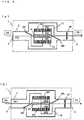
- Fig. 1 is a schematic configuration diagram of a dehumidifying system according to an example configuration when seen from above.
- the dehumidifying system is provided with a main body 1 including an inlet port 3 that sucks indoor air (RA) from an indoor space, which is a dehumidification target space, and an outlet port 4 that supplies humidity-controlled air (SA) to the indoor space, and an air passage 2 through which air flows and that connects the inlet port 3 and the outlet port 4.
- a main body 1 including an inlet port 3 that sucks indoor air (RA) from an indoor space, which is a dehumidification target space, and an outlet port 4 that supplies humidity-controlled air (SA) to the indoor space, and an air passage 2 through which air flows and that connects the inlet port 3 and the outlet port 4.
- RA indoor air
- SA humidity-controlled air
- the air passage 2 includes therein a heating device 50 that heats air, moisture adsorption/desorption devices 10a and 10b that adsorb moisture included in the air or desorb moisture into the air, a cooling device 20 that cools air, an air sending device 30 that blows air inside the air passage 2, and switching devices 40a and 40b that switch between paths of the air that is flowing in the air passage 2.
- FIG. 1 reference characters A and B each denote a path of the air flowing in the air passage 2.
- Fig. 1(a) is a sucking of an air path A
- Fig. 1(b) is that of an air path B.
- the air path A is a path in which indoor air is sucked from the inlet port 3, passes through the heating device 50, the moisture adsorption/desorption device 10a, the cooling device 20, and the moisture adsorption/desorption device 10b, passes through the air sending device 30, and is supplied into the indoor space as humidity-controlled air.
- the air path B is a path in which indoor air is sucked from the inlet port 3, passes through the heating device 50, the moisture adsorption/desorption device 10b, the cooling device 20, and the moisture adsorption/desorption device 10a, passes through the air sending device 30, and is supplied into the indoor space as humidity-controlled air.
- the air path A and the air path B are configured so that they can be switched by the switching devices 40a and 40b after elapse of every predetermined time duration.
- the switching devices 40a and 40b employ a dumper or the like and, although not shown, carries out switching of the air path by controlling the rotation operation of a motor that is used for the dumper operation.
- the timing of the motor rotation operation is set to take place at a predetermined time interval.
- the air passage 2 is structured such that a pipeline connecting the inlet port 3 and the outlet port 4 is bifurcated midway into two directions.
- the switching device 40a is disposed in a portion where this bifurcation starts, and the switching device 40b is disposed in a portion where the bifurcation ends.
- the moisture adsorption/desorption device 10a, the cooling device 20, and the moisture adsorption/desorption device 10b are disposed between the switching device 40a and the switching device 40b, and are disposed in a direction substantially perpendicular to the flow direction of the air flowing from the inlet port 3 towards the outlet port 4.
- the moisture adsorption/desorption devices 10a and 10b each include porous flat plates having pores each with a polygonal section along the cross section of the pipeline in the portion where the moisture adsorption/desorption devices 10a and 10b of the air passage 2 is disposed.
- the pores are structured such that air can pass through in the thickness direction of the porous flat plate.
- the moisture adsorption/desorption devices 10a and 10b in the air passage 2 are structurally disposed as described above, when the cross-sectional area in which the air passes is to be increased, it is only sufficient to enlarge the space (in the left-right direction of Fig.
- the shape of the porous flat plates may be any shape that has pores each with a polygonal section along the cross section of the pipeline and that can achieve the same advantages.
- the moisture adsorption/desorption devices 10a and 10b and the cooling device 20 are disposed substantially in series in the air flowing direction of either of the air paths A and B, and the cooling device 20 is provided between the moisture adsorption/desorption device 10a and the moisture adsorption/desorption device 10b.
- the cooling device 20 is provided between the moisture adsorption/desorption device 10a and the moisture adsorption/desorption device 10b.
- the surfaces of the porous flat plates constituting the moisture adsorption/desorption devices 10a and 10b are coated, surface treated, or impregnated with an adsorbent, such as zeolite, silica gel, or active carbon, having properties such as adsorbing moisture (absorbing moisture) from air that has relatively high humidity and desorbing moisture (releasing moisture) into air that has relatively low humidity.
- an adsorbent such as zeolite, silica gel, or active carbon, having properties such as adsorbing moisture (absorbing moisture) from air that has relatively high humidity and desorbing moisture (releasing moisture) into air that has relatively low humidity.
- adsorbent has a moisture amount that can be adsorbed with respect to the relative humidity of the air (equilibrium adsorption capacity).
- the adsorbent When the adsorbent reaches its equilibrium adsorption capacity after adsorbing moisture from air with a certain relative humidity, the adsorbent reaches an equilibrium state and is unable to adsorb any further amount of moisture. Accordingly, the adsorbent needs to be returned to a state allowing adsorption before reaching an equilibrium state by desorbing moisture into the air.
- the cooling device 20 is provided to cool the air that has passed through the moisture adsorption/desorption device 10a or the moisture adsorption/desorption device 10b to a dew point or lower and to increase the relative humidity of the air, as well as an object to remove the moisture included in the air as condensed water.
- the moisture that has been condensed with the cooling device 20 is drained out of the main body 1 by providing a drainage channel (not shown), for example, that is similar to that of a typical dehumidifying system.
- An evaporator that is a low-temperature-side heat exchanger of the heat pump is used as the cooling device 20, and a high-temperature-side heat exchanger of the heat pump is used as the heating device 50.
- the cooling device 20 and the heating device 50 are connected by pipes (not shown) and constitute a refrigerant circuit.
- a temperature sensor is provided to a pipe of each of the heat exchangers.
- the refrigerant circuit is controlled such that each of the heat exchangers has a heating temperature or a cooling temperature optimum for the dehumidifying operation on the basis of information on temperature measured by the corresponding temperature sensor.
- the air sending device 30 includes a fan and can set the air volume of the air flowing inside the air passage 2 in accordance with the condition of the air.
- a DC motor is used as the motor to rotate the fan
- the air volume can be controlled by varying the current value to control the rotation speed
- the air volume can be controlled by varying the power supply frequency by inverter control to control the rotation speed.
- control of the air volume of the air sending device 30 also changes the flow velocity of the air passing through the moisture adsorption/desorption devices 10a and 10b.
- the adsorption/desorption rate moisture transfer rate between the air and the adsorbent during adsorption/desorption
- the adsorption/desorption capacity of the adsorbent can be increased by increasing the air velocity of the air sending device 30.
- the air sending device 30 is disposed in the most downstream position inside the air passage 2; however, as long as the target air volume in each of the air paths A and B is obtained, the air sending device 30 may be disposed at a position further upstream than the position of disposition in Fig. 1 , such as in the most upstream position inside the air passage 2, and, further, may be disposed in plural numbers such as on the upstream side and on the downstream side; the position of disposition and the number of the air sending devices 30 are not limited.
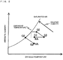
- Fig. 2 is a psychrometric chart illustrating state changes of the air during operation of the dehumidifying system illustrated in Fig. 1 .
- the axis of ordinates of the psychrometric chart in Fig. 2 is absolute humidity of the air and the axis of abscissas thereof is dry-bulb temperature of the air.
- the curved line in Fig. 2 illustrates the saturated air, and the relative humidity of the saturated air is 100%.
- the dotted line in Fig. 2 illustrates a dew point temperature and is the dry-bulb temperature when in a saturated air state.
- the air states are denoted in the psychrometric chart as (1) to (5) which correspond to A(1) to A(5) in Fig. 1(a) , respectively, and to B(1) to B(5) in Fig. 1(b) , respectively.
- the indoor air in state (1) is introduced into the inlet port 3 of the air passage 2 and flows into the heating device 50.
- the air that has flowed into the heating device 50 is heated when passing through the heating device 50.
- the dry-bulb temperature is increased while the absolute humidity is in a substantially uniform state, thus turning the air into state (2).
- This state change is changed in a direction away from the saturated air curve, and, thus, the relative humidity of state (2) is lower than that of state (1).
- the relative humidity of the air is reduced such that the air is changed into a state in which desorption of moisture is facilitated in the moisture adsorption/desorption device 10a through which the air passes next.
- the air in state (2) flows into the moisture adsorption/desorption device 10a. Since the moisture adsorption/desorption device 10a desorbs moisture into the air in accordance with the amount of moisture included in the moisture adsorption/desorption device 10a, the air that has passed through the moisture adsorption/desorption device 10a is humidified; accordingly, the dry-bulb temperature is reduced and, further, the absolute humidity is increased, turning the air into state (3). Furthermore, the dew point temperature is increased due to increase in absolute humidity.
- the reduction in dry-bulb temperature is caused by endothermic reaction during desorption of the moisture adsorption/desorption device 10a.
- the air in state (3) flows into the cooling device 20.
- the air that has flowed into the cooling device 20 is cooled to a dew point temperature or lower when passing through the cooling device 20 and is turned into state (4).
- moisture amounting to the difference between that of the absolute humidity of state (3) and that of the absolute humidity of state (4) is condensed, and, thus, the air is dehumidified.
- the cooling turns the air into saturated air and the relative humidity of the air is increased to approximately 100%.
- the air is dehumidified and, further, the relative humidity of the air is increased such that the air is changed into a state in which adsorption of moisture is facilitated in the moisture adsorption/desorption device 10b through which the air passes next.
- the air in state (4) flows into the moisture adsorption/desorption device 10b. Since the moisture adsorption/desorption device 10b absorbs moisture from the air in accordance with the amount of moisture included in the moisture adsorption/desorption device 10b, the air that has passed through the moisture adsorption/desorption device 10b is dehumidified; accordingly, the dry-bulb temperature is increased and, further, the absolute humidity is reduced, turning the air into state (5).
- the increase in dry-bulb temperature is caused by exothermic reaction during adsorption of the moisture adsorption/desorption device 10b.
- the air is dehumidified and is changed into humidity-controlled air that is to be supplied to the indoor space.
- the air in state (5) is supplied to the indoor space as humidity-controlled air from the outlet port 4 of the air passage 2 via the air sending device 30.
- the indoor air in state (1) is introduced into the inlet port 3 of the air passage 2 and flows into the heating device 50.
- the air that has flowed into the heating device 50 is heated when passing through the heating device 50.
- the dry-bulb temperature is increased while the absolute humidity is in a substantially uniform state, thus turning the air into state (2).
- This state change is in a direction away from the saturated air curve, and, thus, the relative humidity of state (2) is lower than that of state (1).
- the relative humidity of the air is reduced such that the air is changed into a state in which desorption of moisture is facilitated in the moisture adsorption/desorption device 10b through which the air passes next.
- the air in state (2) flows into the moisture adsorption/desorption device 10b. Since the moisture adsorption/desorption device 10b desorbs moisture into the air in accordance with the amount of moisture included in the moisture adsorption/desorption device 10b, the air that has passed through the moisture adsorption/desorption device 10b is humidified; accordingly, the dry-bulb temperature is reduced and, further, the absolute humidity is increased, turning the air into state (3). Furthermore, the dew point temperature is increased due to increase in absolute humidity.
- the reduction in dry-bulb temperature is caused by endothermic reaction during desorption of the moisture adsorption/desorption device 10b.
- the air in state (3) flows into the cooling device 20.
- the air that has flowed into the cooling device 20 is cooled to a dew point temperature or lower when passing through the cooling device 20 and is turned into state (4).
- moisture amounting to the difference between that of the absolute humidity of state (3) and that of the absolute humidity of state (4) is condensed, and, thus, the air is dehumidified.
- the cooling turns the air into saturated air and the relative humidity of the air is increased to approximately 100%.
- the air is dehumidified and, further, the relative humidity of the air is increased such that the air is changed into a state in which adsorption of moisture is facilitated in the moisture adsorption/desorption device 10a through which the air passes next.
- the air in state (4) flows into the moisture adsorption/desorption device 10a. Since the moisture adsorption/desorption device 10a absorbs moisture from the air in accordance with the amount of moisture included in the moisture adsorption/desorption device 10a, the air that has passed through the moisture adsorption/desorption device 10a is dehumidified; accordingly, the dry-bulb temperature is increased and, further, the absolute humidity is reduced, turning the air into state (5).
- the increase in dry-bulb temperature is caused by exothermic reaction during adsorption of the moisture adsorption/desorption device 10a.
- the air is dehumidified and is changed into humidity-controlled air that is to be supplied to the indoor space.
- the air in state (5) is supplied to the indoor space as humidity-controlled air from the outlet port 4 of the air passage 2 via the air sending device 30.
- the switching between the air path A and the air path B is carried out by operating the switching devices 40a and 40b.
- the switching between the air path A and the air path B makes the moisture adsorption/desorption device 10a that has been carrying out desorption reaction in the air path A to carry out adsorption reaction in the air path B, and makes the moisture adsorption/desorption device 10b that has been carrying out adsorption reaction in the air path A to carry out desorption reaction in the air path B.
- the switching devices 40a and 40b since the moisture adsorption/desorption devices 10a and 10b do not reach an equilibrium state, it is possible to carry out the dehumidifying operation continuously.
- the switching of the air paths A and B with the switching devices 40a and 40b is controlled such that the switching is carried out at a predetermined time interval. For example, control is carried out such that the air paths are switched every three minutes.
- the dehumidifying system of the invention is not for use in dehumidifying operations of air in a large space where environmental change is large, such as an outdoor space.
- the dehumidifying system is for carrying out dehumidifying operations with air that is in a small space where environmental change is small, such as an indoor space. Accordingly, it is easier to estimate the condition in which the moisture adsorption/desorption devices 10a and 10b reach an equilibrium state.
- the switching time interval settings for optimizing the dehumidification capacity can be changed by external operation.
- optimization of the dehumidification capacity can be achieved by varying the rotation speed of the desiccant rotor; however, since there exists a sliding surface, when the rotation speed increases, the frictional resistance of the rotating shaft increases and unnecessary input tends to increase.
- the dehumidifying system of the invention employs the moisture adsorption/desorption devices 10a and 10b that do not have any sliding surface and can obtain the same advantages by varying the switching time interval of the switching devices 40a and 40b; hence there occurs no unnecessary input caused by friction and the system is energy-saving.
- the moisture adsorption/desorption device 10a and the moisture adsorption/desorption device 10b are disposed substantially in series in the direction of the air flow inside the single air passage 2 and the switching devices 40a and 40b switch the air paths; accordingly, there occurs no reduction in the dehumidification capacity due to air leakage from the sliding surface unlike in the case of the desiccant rotor. Additionally, since there is no sliding surface in the moisture adsorption/desorption devices 10a and 10b, it is possible to improve the durability of the dehumidifying system.
- the flow directions of the air in the moisture adsorption/desorption devices 10a and 10b during adsorption and desorption are opposite to each other and the direction of the air passing therethrough during adsorption and desorption is reversed; accordingly, it is possible to increase the dehumidification/humidification efficiency.
- the moisture adsorption/desorption devices 10a and 10b are secured and are motionless, there is no geometrical restriction in order to allow rotational motion or the like as in the case of the desiccant rotor; accordingly, it is possible to match the air passage area of the moisture adsorption/desorption devices 10a and 10b with the shape of the air passage 2. It is further possible to reduce pressure loss by increasing the air passage area and reducing the air velocity, and to increase the adsorption/desorption amount by increasing the area of the adsorbent of the moisture adsorption/desorption devices 10a and 10b that is in contact with the air.
- the air passing through the cooling device 20 has a high dew point temperature since humidification is carried out by the desorption reaction of the moisture adsorption/desorption device 10a or the moisture adsorption/desorption device 10b. Accordingly, it is possible to condense and dehumidify the air that has passed through the cooling device 20 even in a case in which the temperature of the cooling section of the cooling device 20 is set high; accordingly, the input to the cooling device 20 can be reduced, compared to the input in which a similar dehumidification is carried out with the cooling device 20 alone.
- the air that has passed through the cooling device 20 is dehumidified with the adsorption reaction of the moisture adsorption/desorption device 10b or 10a, it is possible to dehumidify a larger amount of air, compared to a case in which dehumidification is carried out with the cooling device 20 alone with the same cooling section temperature.
- the heating temperature of the heating device 50 it is possible to make the temperature of the air of the indoor space and the temperature of the humidity-controlled air to be the same; accordingly, it is possible to carry out isothermal dehumidification.
- the problems of the known rotating desiccant rotor have been overcome.
- the heating device 50 serving as a desorption heat source is provided in order to increase the desorption capacity of the moisture adsorption/desorption devices 10a and 10b, the quantity of heat provided by the heating device 50 contained in the air needs to be treated by the cooling device 20, leading to decrease in treatment efficiency of the sensible heat and the latent heat.
- an adsorbent with properties such as a large equilibrium adsorption capacity (the moisture amount that can be adsorbed with respect to the relative humidity of the air) at relative humidity ranging from 80 to 100% and a large difference between the equilibrium adsorption capacity at relative humidity ranging from 80 to 100% and an equilibrium adsorption capacity at relative humidity ranging from 40 to 60% is employed.
- a large equilibrium adsorption capacity the moisture amount that can be adsorbed with respect to the relative humidity of the air
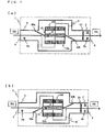
- Fig. 3 is a schematic configuration diagram of the dehumidifying system according to the first embodiment of the invention when seen from above. Note that parts same as those in Fig. 1 are designated by like reference numerals and description thereof is omitted.
- FIG. 3 reference characters C and D each denotes a path of the air flowing in the air passage 2.
- Fig. 3(a) is a sucking of an air path C
- Fig. 3(b) is that of an air path D.
- the air path C is a path in which indoor air is sucked from the inlet port 3, passes through a moisture adsorption/desorption device 10c, a cooling device 21, and a moisture adsorption/desorption device 10d, passes through the air sending device 30, and is supplied into the indoor space as humidity-controlled air.
- the air path D is a path in which indoor air is sucked from the inlet port 3, passes through the moisture adsorption/desorption device 10d, the cooling device 21, and the moisture adsorption/desorption device 10c, passes through the air sending device 30, and is supplied into the indoor space as humidity-controlled air from the outlet 4.
- the moisture adsorption/desorption devices 10c and 10d and the cooling device 21 are disposed substantially in series in the air flowing direction of either of the air paths C and D, and the cooling device 21 is provided between the moisture adsorption/desorption device 10c and the moisture adsorption/desorption device 10d.
- the moisture adsorption/desorption devices 10c and 10d each include porous flat plates having pores each with a polygonal section along the cross section of the pipeline in the portion of the air passage 2 where the moisture adsorption/desorption devices 10c and 10d is disposed.
- the pores are structured such that air can pass through in the thickness direction of the porous flat plate.
- the surfaces of the porous flat plates are coated, surface treated, or impregnated with an adsorbent having properties such as adsorbing moisture from air that has relatively high humidity and desorbing moisture into air that has relatively low humidity, and a large equilibrium adsorption capacity at relative humidity ranging from 80 to 100% and a large difference between the equilibrium adsorption capacity at relative humidity ranging from 80 to 100% and an equilibrium adsorption capacity at relative humidity ranging from 40 to 60%.
- an adsorbent having properties such as adsorbing moisture from air that has relatively high humidity and desorbing moisture into air that has relatively low humidity, and a large equilibrium adsorption capacity at relative humidity ranging from 80 to 100% and a large difference between the equilibrium adsorption capacity at relative humidity ranging from 80 to 100% and an equilibrium adsorption capacity at relative humidity ranging from 40 to 60%.
- Fig. 4 a relationship between the relative humidity and the equilibrium adsorption capacity of the adsorbent employed in the moisture adsorption/desorption devices 10c and 10d are illustrated.
- the axis of ordinates is the equilibrium adsorption capacity
- the axis of abscissas is the relative humidity.
- the solid-line curve illustrates a property of the adsorbent employed in the moisture adsorption/desorption devices 10c and 10d
- the broken-line curve illustrates a property of a known adsorbent employed in, for example, the moisture adsorption/desorption devices 10a and 10b of the example configuration.
- the adsorbent employed in the moisture adsorption/desorption devices 10c and 10d have properties such as the equilibrium adsorption capacity increasing in a substantially linear manner with respect to the air with a relative humidity ranging from 40 to 100%, and an especially large equilibrium adsorption capacity in the high-humidity region (relative humidity ranging from 80 to 100%). That is, the adsorption/desorption capacity can be increased by increasing the difference between the relative humidity of the air that passes through the moisture adsorption/desorption devices 10c and the relative humidity of the air that passes through the moisture adsorption/desorption devices 10d during adsorption and desorption of the moisture adsorption/desorption devices 10c and 10d.
- the equilibrium adsorption capacity of known adsorbents increases only slightly with respect to the increase in relative humidity. Accordingly, when dehumidification of air (relative humidity ranging from about 40 to approximately 60%) in a typical indoor space is carried out using a known adsorbent, the air needs to be heated with a heating device or the like before desorption to reduce the relative humidity of the air to approximately 20% in order to create a difference between the equilibrium adsorption capacity of the adsorbent in which the air passes during adsorption and the equilibrium adsorption capacity of the adsorbent in which the air passes during desorption.
- the dehumidifying system according to the first embodiment of the invention employs, in the moisture adsorption/desorption devices 10c and 10d, an adsorbent that has an especially large equilibrium adsorption capacity in the high-humidity region (relative humidity ranging from 80 to 100%); hence, it is possible to create sufficient difference with the equilibrium adsorption capacity with respect to the air (relative humidity ranging from about 40 to approximately 60%) in a typical indoor space without heating the indoor air and reducing the relative humidity.
- a dehumidifying operation can be carried out without a desorption heat source in the air passage 2, and consequently, the heating device 50 of the example configuration is omitted and downsizing of the system is allowed.
- the cooling device 21 does not need to carry out treatment of the quantity of heat provided by the heating device 50 contained in the air. Accordingly, the cooling device 21 only carries out heat treatment of the indoor air and, thus, energy is saved.
- the temperature difference between the temperature of the moisture adsorption/desorption device 10c and that of the moisture adsorption/desorption device 10d becomes small when the air passage is switched during the dehumidifying operation and, further, the temperature difference between the temperature of the moisture adsorption/desorption devices 10c and 10d and that of the air passing through the moisture adsorption/desorption devices 10c and 10d becomes small; hence, thermal resistance of the adsorbent generated by the temperature difference between the passing air of the moisture adsorption/desorption devices 10c and 10d and the moisture adsorption/desorption devices 10c and 10d is reduced and it is possible to carry out the dehumidifying operation with high efficiency.
- An adsorbent having such properties includes, sodium polyacrylate crosslinked product as for organic adsorbents, and nanotube silicate (imogolite) or aluminum silicate (HASclay) as for inorganic adsorbents.
- the cooling device 21 employs a brine cooler or the like, and although not shown, brine that has been cooled by a brine circuit is made to pass through pipes of a fin-and-tube heat exchanger. Air is cooled by passing through this heat exchanger.
- the cooling temperature is measured by a temperature sensor (not shown) provided to a pipe of the heat exchanger and is controlled so as to become an optimum temperature for the dehumidifying operation. Furthermore, by controlling the temperature of the brine passing through the pipes with this temperature sensor, the temperature of the humidity-controlled air supplied to the indoor space can be turned into the externally set target temperature.
- cooling device 21 When a brine cooler is used as the cooling device 21, cooling is carried out with brine that has exchanged heat in a refrigerating machine that is separately provided outside the main body 1; accordingly, cooling capacity can be obtained without a high-temperature heating source such as the heating device 50 of the example configuration. Accordingly, a heating device can be omitted in the main body 1 and downsizing of the dehumidifying system is allowed.
- Fig. 5 is a psychrometric chart illustrating state changes of the air during operation of the dehumidifying system illustrated in Fig. 3 .
- the air states are denoted in the psychrometric chart as (1) to (4) which correspond to C(1) to C(4) in Fig. 3(a) , respectively, and to D(1) to D(4) in Fig. 3(b) , respectively.
- the indoor air in state (1) is introduced into the inlet port 3 of the air passage 2 and flows into the moisture adsorption/desorption device 10c. Since the moisture adsorption/desorption device 10c desorbs moisture into the air in accordance with the amount of moisture included in the moisture adsorption/desorption device 10c, the air that has passed through the moisture adsorption/desorption device 10c is humidified; accordingly, the dry-bulb temperature is reduced and, further, the absolute humidity is increased, turning the air into state (2). Furthermore, the dew point temperature is increased due to increase in absolute humidity.
- the reduction in dry-bulb temperature is caused by endothermic reaction during desorption of the moisture adsorption/desorption device 10c.
- the air is humidified and the dew point temperature is increased such that the air is changed into a state in which condensation of moisture is facilitated in the cooling device 21 through which the air passes next.
- the air in state (2) flows into the cooling device 21.
- the air that has flowed into the cooling device 21 is cooled to a dew point temperature or lower when passing through the cooling device 21 and is turned into state (3).
- moisture amounting to the difference between that of the absolute humidity of state (2) and that of the absolute humidity of state (3) is condensed, and, thus, the air is dehumidified.
- the cooling turns the air into saturated air and the relative humidity of the air is increased to approximately 100%.
- the air is dehumidified and, further, the relative humidity of the air is increased such that the air is changed into a state in which adsorption of moisture is facilitated in the moisture adsorption/desorption device 10d through which the air passes next.
- the air in state (3) flows into the moisture adsorption/desorption device 10d. Since the moisture adsorption/desorption device 10d absorbs moisture from the air in accordance with the amount of moisture included in the moisture adsorption/desorption device 10d, the air that has passed through the moisture adsorption/desorption device 10d is dehumidified; accordingly, the dry-bulb temperature is increased and, further, the absolute humidity is reduced, turning the air into state (4).
- the increase in dry-bulb temperature is caused by exothermic reaction during adsorption of the moisture adsorption/desorption device 10d.
- the air is dehumidified and is changed into humidity-controlled air that is to be supplied to the indoor space.
- the air in state (4) is supplied to the indoor space as humidity-controlled air from the outlet port 4 of the air passage 2 via the air sending device 30.
- the indoor air in state (1) is introduced into the inlet port 3 of the air passage 2 and flows into the moisture adsorption/desorption device 10d. Since the moisture adsorption/desorption device 10d desorbs moisture into the air in accordance with the amount of moisture included in the moisture adsorption/desorption device 10d, the air that has passed through the moisture adsorption/desorption device 10d is humidified; accordingly, the dry-bulb temperature is reduced and, further, the absolute humidity is increased, turning the air into state (2). Furthermore, the dew point temperature is increased due to increase in absolute humidity.
- the reduction in dry-bulb temperature is caused by endothermic reaction during desorption of the moisture adsorption/desorption device 10d.
- the air is humidified and the dew point temperature is increased such that the air is changed into a state in which condensation of moisture is facilitated in the cooling device 21 through which the air passes next.
- the air in state (2) flows into the cooling device 21.
- the air that has flowed into the cooling device 21 is cooled to a dew point temperature or lower when passing through the cooling device 21 and is turned into state (3).
- moisture amounting to the difference between that of the absolute humidity of state (2) and that of the absolute humidity of state (3) is condensed, and, thus, the air is dehumidified.
- the cooling turns the air into saturated air and the relative humidity of the air is increased to approximately 100%.
- the air is dehumidified and, further, the relative humidity of the air is increased such that the air is changed into a state in which adsorption of moisture is facilitated in the moisture adsorption/desorption device 10c through which the air passes next.
- the air in state (3) flows into the moisture adsorption/desorption device 10c. Since the moisture adsorption/desorption device 10c absorbs moisture from the air in accordance with the amount of moisture included in the moisture adsorption/desorption device 10c, the air that has passed through the moisture adsorption/desorption device 10c is dehumidified; accordingly, the dry-bulb temperature is increased and, further, the absolute humidity is reduced, turning the air into state (4).
- the increase in dry-bulb temperature is caused by exothermic reaction during adsorption of the moisture adsorption/desorption device 10c.
- the air is dehumidified and is changed into humidity-controlled air that is to be supplied to the indoor space.
- the air in state (4) is supplied to the indoor space as humidity-controlled air from the outlet port 4 of the air passage 2 via the air sending device 30.
- the switching operation of the air paths C and D with the switching devices 40a and 40b is, similar to the example configuration, controlled so as to be carried out at a constant time period and, thus, advantages similar to that of the example configuration can be obtained.
- the adsorption/desorption rate moisture transfer rate between the air and the adsorbent during adsorption/desorption
- the adsorbent that is used in the moisture adsorption/desorption devices 10c and 10d has air velocity dependence in addition to temperature dependence; accordingly, the higher the temperature becomes, the higher the adsorption/desorption rate becomes.
- Fig. 6 illustrates a relationship between the air passage velocity and the adsorption/desorption rate of the adsorbent used in the moisture adsorption/desorption device of the dehumidifying system.
- the axis of ordinates of Fig. 6 is the adsorption/desorption rate of the adsorbent and the axis of abscissas is the air passage velocity of the air passing through the adsorbent.
- T1 and T2 of Fig. 6 are temperatures of the air passing through the adsorbent during adsorption or desorption. T1 is higher than T2, and T1 having higher temperature has higher desorption rate.
- T1 is the air temperature during desorption and T2 is the air temperature during adsorption
- T2 is the air temperature during adsorption
- the dehumidifying system according to the first embodiment of the invention does not heat the air during desorption; accordingly, the temperature difference during adsorption and that during desorption is smaller than the temperate difference when there is a desorption heat source. In Therefore, the difference between the adsorption rate and the desorption rate is smaller. Accordingly, the adsorption rate and the desorption rate become close to each other, allowing the adsorption/desorption capacity of the adsorbent to be used efficiently.
- a dehumidifying system disposes various sensors in the air passage 2 and switches the air paths C and D on the basis of information on the air state obtained by the sensors. With this, it is possible to keep the dehumidification capacity to a more optimum state and continue an optimum dehumidifying operation even when there is change in the state of the indoor air during the dehumidifying operation.
- Fig. 7 is a schematic configuration diagram of the dehumidifying system according to the second embodiment of the invention when seen from above.
- Fig. 7(a) is a sucking of the air path C
- Fig. 7(b) is that of the air path D. Note that parts same as those in Fig. 3 are designated by like reference numerals and description thereof is omitted.
- temperature-humidity sensors 5a and 5b that each measure temperature and humidity (it may be relative humidity or absolute humidity, wet-bulb temperature, or dew point temperature, hereinafter, the description "humidity" of the temperature-humidity sensor denotes a similar meaning) are disposed in the inlet port 3 and the outlet port 4 of the air passage 2.
- the temperature-humidity sensor 5a measures the temperature and humidity of the indoor air that has passed through the inlet port 3
- the temperature-humidity sensor 5b measures the temperature and humidity of the humidity-controlled air that passes through the outlet port 4.
- a temperature sensor 6 is disposed in the cooling device 21.
- the temperature sensor 6 measures the cooling section temperature of the cooling device 21.
- an air velocity sensor 7 that measures the air velocity is disposed in the outlet port 4.
- the air velocity sensor 7 measures the air velocity of the humidity-controlled air passing through the outlet port 4.
- thermometers 5a and 5b since any device is applicable as long as the temperature of the measured area and any one of the relative humidity, the absolute humidity, the dew point temperature, and the wet-bulb temperature are known, measurements are carried out by two sensors such as a dry-bulb thermometer and a wet-bulb thermometer, and the number of the sensors is not limited.
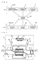
- Fig. 8 a control block diagram of the dehumidifying system with the temperature-humidity sensors 5a and 5b, the temperature sensor 6, and the air velocity sensor 7 is illustrated.
- Each of the sensors is connected to a control device 8a that controls the dehumidifying system.
- the control device 8a acquires information on temperature-humidity, temperature, and air velocity from each of the respective sensors and, on the basis of these pieces of information, controls the cooling temperature of the cooling device 21, the air volume of the air sending device 30, and the switching operation of the switching devices 40a and 40b.
- the absolute humidity of the humidity-controlled air is invariably lower than the absolute humidity of the indoor air since desorption and adsorption are carried out by the moisture adsorption/desorption devices 10c and 10d. Furthermore, when the moisture adsorption/desorption devices 10c and 10d approaches an equilibrium state after continuance of the dehumidifying operation, the adsorption/desorption capacity becomes small and the difference between the absolute humidity of the humidity-controlled air and the absolute humidity of the indoor air becomes small.
- the control device 8a carries out switching of the air paths on the basis of this change in absolute humidity.
- the temperature-humidity sensor 5a measures the absolute humidity of the indoor air and the temperature-humidity sensor 5b measures the absolute humidity of the humidity-controlled air. Information on the absolute humidity measured by the temperature-humidity sensors 5a and 5b is sent to the control device 8a at all times. When the difference in absolute humidity becomes smaller than a preset threshold value, the control device 8a drives the switching devices 40a and 40b, and switches the air path C to the air path D or switches the air path D to the air path C.
- the switching timing of the switching devices 40a and 40b is automatically modified on the basis of the information acquired by the sensors; accordingly, sudden drop in the adsorption/desorption capacity can be prevented and it is possible to continue the continuous dehumidifying operation.
- the moisture adsorption/desorption device 10d or the moisture adsorption/desorption device 10c adsorbs moisture from the air and also releases heat; accordingly, the air temperature rises. Furthermore, when the equilibrium state is approached after continuance of the dehumidifying operation, the adsorption/desorption capacity becomes small along with a drop in the amount of heat release.
- the control device 8a carries out switching of the air paths on the basis of this change in temperature.
- the temperature sensor 6 measures the cooling section temperature of the cooling device 21, and the temperature-humidity sensor 5b measures the temperature of the humidity-controlled air. Information on the temperature measured by the temperature sensor 6 and the temperature-humidity sensor 5b is sent to the control device 8a at all times. When the difference in temperature becomes smaller than a preset threshold value, the control device 8a drives the switching devices 40a and 40b, and switches the air path C to the air path D or switches the air path D to the air path C.
- the switching timing of the switching devices 40a and 40b is automatically modified on the basis of the information acquired by the sensors; accordingly, sudden drop in the adsorption/desorption capacity can be prevented and it is possible to continue the continuous dehumidifying operation.
- Air volume control of the air sending device 30 in which the air velocity sensor 7 is used will be described next.
- the air volume control of the air sending device 30 is carried out in a case, such as when the space that is subject to dehumidification of the dehumidifying system of the invention is changed.
- the air velocity of the air sending device 30 is increased on the basis of the air velocity sensor 7.
- the adsorption/desorption rate of the moisture adsorption/desorption devices 10c and 10d has air velocity dependence, and, In this way, when the air velocity is increased, the adsorption/desorption rate is also increased and the dehumidification capacity is increased.
- the absolute humidity of the indoor air is decreased as time passes. At this time, when the absolute humidity of the indoor air does not change, it can be considered that the dehumidification capacity is lacking due to the largeness of the dehumidification target space.
- the control device 8a carries out control such that the air velocity of the air sending device 30 is increased on the basis of the air velocity sensor 7. In this way, it is possible to exert sufficient dehumidification capacity even in a case in which the dehumidification target space is large.
- the dehumidifying system according to the example configuration can be provided with the various sensors in the same manner as the second embodiment and carry out switching control with the various sensors, as well as carrying out the control of switching the switching devices 40a and 40b at a constant time interval. In this way, a further optimum dehumidifying operation can be carried out.
- Fig. 9 is a schematic configuration diagram of the dehumidifying system according to a third embodiment of the invention when seen from above. Note that parts same as those in Fig. 7 are designated by like reference numerals and description thereof is omitted.
- the dehumidifying system includes a main body 1a and a main body 1b, and the main body 1a is provided with a compressor 60, a condenser 70, and an expansion valve 80 that are connected with pipes to an evaporator 22 provided inside the air passage 2 inside the main body 1b, and, thus, a refrigerant circuit 100 is constituted.
- the evaporator 22 is provided inside the air passage 2 as a cooling device.
- the main body 1a is provided with an air sending device 31 configured to carry out air-cooling of the condenser 70.
- the main body 1a and the main body 1b are connected by the pipes of the refrigerant circuit 100 and wiring such as a power source and signal wires.
- the compressor 60, the condenser 70, the expansion valve 80, and a suction side of the evaporator 22 constitute a circuit in this order.
- the refrigerant used in the refrigerant circuit 100 is not limited to a particular refrigerant and includes a natural refrigerant such as carbon dioxide, hydrocarbon, or helium; a refrigerant that does not contain chlorine such as HFC410A or HFC407C; or a fluorocarbon refrigerant such as R22 or R134 that is used in known products.
- a natural refrigerant such as carbon dioxide, hydrocarbon, or helium
- a refrigerant that does not contain chlorine such as HFC410A or HFC407C
- a fluorocarbon refrigerant such as R22 or R134 that is used in known products.
- various types such as a reciprocal, rotary, scroll, or screw type may be applied.
- a high-temperature high-pressure gasified refrigerant that has been compressed first by the compressor 60 flows into the condenser 70.
- the refrigerant changes its phase from the high-temperature high-pressure gas to liquid in the condenser 70 and heats the air passing through the condenser 70.
- the refrigerant is decompressed through the expansion valve 80.
- the refrigerant turns into a two-phase state in which a low-temperature low-pressure liquid and gas are mixed, and flows into the evaporator 22.
- the refrigerant changes its phase from liquid to gas and cools the air passing through the evaporator 22.
- the refrigerant flows into the compressor 60 and turns into a high-temperature high-pressure gas again.
- a temperature sensor 6a that detects a pipe temperature of the evaporator 22
- a temperature sensor 6b that detects a pipe temperature of the condenser 70
- a temperature sensor 6c for detection of a discharge temperature on the discharge side of the compressor 60 are provided instead of the temperature sensor 6 that is used in the second embodiment. Note that the manner in which the air in the air passage 2 flows and the basic state changes of the air in the air passage 2 are the same as those of the second and second embodiments; accordingly, description thereof will be omitted.
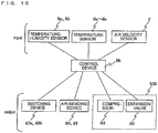
- a control block diagram with the temperature-humidity sensors 5a and 5b, the temperature sensors 6a to 6c, and the air velocity sensor 7 is illustrated. These sensors are connected to a control device 8b that controls the dehumidifying system.
- the control device 8b acquires information on temperature-humidity, temperature, and air velocity from each of the respective sensors and, on the basis of these pieces of information, controls the frequency of the compressor 60, the opening degree of the expansion valve 80, the air volume of the air sending devices 30 and 31, and the switching operation of the switching devices 40a and 40b.
- the refrigerant evaporating temperature of the evaporator 22 is controlled by controlling the opening degree of the expansion valve 80. Note that the controls of the air volume of the air sending device 30 and the switching of the switching devices 40a and 40b are the same as those of the second embodiment.
- the dehumidifying system obtained as above can carry out highly efficient dehumidification by using the evaporator 22 of the heat pump instead of the cooling device 21, and can control the temperature of the humidity-controlled air supplied to the indoor space by changing the evaporating temperature of the refrigerant by changing the frequency of the compressor 60 and the opening degree of the expansion valve 80.
- the adsorbent with a property of having an especially large equilibrium adsorption capacity when the relative humidity ranges from 80 to 100% and a property of the equilibrium adsorption capacity increasing with respect to the increase of the relative humidity is used; hence, there is no need to employ a condenser 70 of the heat pump as a desorption heat source during desorption. Accordingly, it is possible to dispose the condenser 70 in a space (outdoor space, for example) different from the dehumidification target space (indoor space, for example). With the above arrangement, there will be no influence of the heat of the condenser 70 to the dehumidification target space and dehumidification with high efficiency can be carried out.
- the air volume of the air sending device 31 disposed with the condenser 70 it is possible to control the condensing temperature of the refrigerant, and, as a result of reducing the difference between the evaporating temperature and the condensing temperature, the efficiency of the heat pump can be increased.
Landscapes
- Engineering & Computer Science (AREA)
- Chemical & Material Sciences (AREA)
- Combustion & Propulsion (AREA)
- Mechanical Engineering (AREA)
- General Engineering & Computer Science (AREA)
- Analytical Chemistry (AREA)
- General Chemical & Material Sciences (AREA)
- Oil, Petroleum & Natural Gas (AREA)
- Chemical Kinetics & Catalysis (AREA)
- Drying Of Gases (AREA)
- Central Air Conditioning (AREA)
- Air Conditioning Control Device (AREA)
Claims (10)
- Système de déshumidification, comprenant :un corps principal (1) qui inclut un orifice d'entrée (3) pour aspirer de l'air à partir d'un espace cible de déshumidification et un orifice de sortie (4) pour fournir de l'air à l'espace cible de déshumidification ;un passage d'air (2) prévu dans le corps principal (1), le passage d'air (2) raccordant l'orifice d'entrée (3) et l'orifice de sortie (4) ;un premier dispositif d'adsorption/de désorption d'humidité (10c) disposé dans le passage d'air (2) et incluant un adsorbant pour désorber de l'humidité dans de l'air avec une basse humidité relative, et pour adsorber de l'humidité à partir d'air avec une haute humidité relative ;un second dispositif d'adsorption/de désorption d'humidité (10d) disposé dans le passage d'air (2) et disposé afin d'être espacé du premier dispositif d'adsorption/de désorption d'humidité (10c), le second dispositif d'adsorption/de désorption d'humidité (10d) incluant un adsorbant pour désorber de l'humidité dans de l'air avec une basse humidité relative, et pour adsorber de l'humidité à partir d'air avec une haute humidité relative ;un dispositif de refroidissement (21) disposé entre le premier dispositif d'adsorption/de désorption d'humidité (10c) et le second dispositif d'adsorption/de désorption d'humidité (10d), le dispositif de refroidissement (21) refroidissant de l'air qui a été humidifié par désorption d'humidité à partir du premier dispositif d'adsorption/de désorption d'humidité (10c) ou du second dispositif d'adsorption/de désorption d'humidité (10d) ; etdes dispositifs de permutation (40a, 40b) disposés dans le passage d'air (2), les dispositifs de permutation (40a, 40b) permutant entre un premier chemin (C) dans lequel l'air aspiré à partir de l'orifice d'entrée (3) passe à travers le premier dispositif d'adsorption/de désorption d'humidité (10c), le dispositif de refroidissement (21), et le second dispositif d'adsorption/de désorption d'humidité (10d) dans cet ordre, et un second chemin (D) dans lequel l'air aspiré à partir de l'orifice d'entrée (3) passe à travers le second dispositif d'adsorption/de désorption d'humidité (10d), le dispositif de refroidissement (21), et le premier dispositif d'adsorption/de désorption d'humidité (10c) dans cet ordre,caractérisé en ce que l'adsorbant prévu pour chacun des premier et second dispositifs d'adsorption/de désorption d'humidité (10c, 10d) a une capacité d'adsorption d'équilibre par rapport à de l'air avec une humidité relative variant de 40 à 100 % augmente de manière sensiblement linéaire par rapport à une augmentation de l'humidité relative,dans lequel le premier dispositif d'adsorption/de désorption d'humidité (10c), le dispositif de refroidissement (21) et le second dispositif d'adsorption/de désorption d'humidité (10d) sont disposés en série dans la direction d'écoulement d'air dans le passage d'air pour que des côtés à travers lesquels de l'air passe se fassent face, etle système de déshumidification est configuré pour réaliser une désorption de manière telle que, durant la désorption, l'air aspiré à partir de l'orifice d'entrée s'écoule dans le premier dispositif d'adsorption/de désorption d'humidité (10c) et le second dispositif d'adsorption/de désorption d'humidité (10d) sans être chauffé pour réduire l'humidité relative.
- Système de déshumidification selon la revendication 1, dans lequel le premier dispositif d'adsorption/de désorption d'humidité (10c) et le second dispositif d'adsorption/de désorption d'humidité (10d) sont fixés et immobilisés dans le passage d'air (2).
- Système de déshumidification selon la revendication 1 ou 2, dans lequel le premier dispositif d'adsorption/de désorption d'humidité (10c) et le second dispositif d'adsorption/de désorption d'humidité (10d) sont des corps ventilateurs incluant chacun un grand nombre de petits trous débouchants.
- Système de déshumidification selon l'une quelconque de la revendication 1 à 3, dans lequel le premier dispositif d'adsorption/de désorption d'humidité (10c) et le second dispositif d'adsorption/de désorption d'humidité (10d) sont disposés de telle sorte que des surfaces de passage d'air du premier dispositif d'adsorption/de désorption d'humidité (10c) et du second dispositif d'adsorption/de désorption d'humidité (10d) fassent face à des surfaces de passage d'air du dispositif de refroidissement (21).
- Système de déshumidification selon l'une quelconque des revendications 1 à 4, dans lequel le premier dispositif d'adsorption/de désorption d'humidité (10c), le dispositif de refroidissement (21), et le second dispositif d'adsorption/de désorption d'humidité (10d) sont disposés de telle sorte qu'une direction d'air passant à travers le premier dispositif d'adsorption/de désorption d'humidité (10c), le dispositif de refroidissement (21), et le second dispositif d'adsorption/de désorption d'humidité (10d) soit inversée en permutant entre les premier et second chemins de l'air.
- Système de déshumidification selon l'une quelconque des revendications 1 à 5, dans lequel
le passage d'air (2) inclut une première portion de bifurcation qui est prévue sur un côté amont du premier dispositif d'adsorption/de désorption d'humidité (10c) et du second dispositif d'adsorption/de désorption d'humidité (10d) et qui fait bifurquer un chemin en deux directions, et une seconde portion de bifurcation qui est prévue sur un côté aval du premier dispositif d'adsorption/de désorption d'humidité (10c) et du second dispositif d'adsorption/de désorption d'humidité (10d) et qui fait bifurquer un chemin en deux directions, et
les dispositifs de permutation (40a, 40b) sont chacun disposés dans la première portion de bifurcation et la seconde portion de bifurcation. - Système de déshumidification selon l'une quelconque des revendications 1 à 6, comprenant en outre un dispositif de commande (8a) configuré pour commander une opération de permutation des dispositifs de permutation (40a, 40b) pour qu'elle soit réalisée à un intervalle temporel prédéterminé.
- Système de déshumidification selon l'une quelconque des revendications 1 à 6, comprenant en outre :un premier capteur (5a) configuré pour mesurer des informations d'humidité d'air qui est passé à travers l'orifice d'entrée (3) ;un second capteur (5b) configuré pour mesurer des informations d'humidité d'air qui doit passer à travers l'orifice de sortie (4) ; etun dispositif de commande (8a) configuré pour commander une opération de permutation des dispositifs de permutation (40a, 40b) sur la base d'informations d'humidité mesurées par les premier (5a) et second (5b) capteurs.
- Système de déshumidification selon l'une quelconque des revendications 1 à 6, comprenant en outre :un premier capteur (5a) configuré pour mesurer des informations d'humidité d'air qui est passé à travers l'orifice d'entrée (3) ;un second capteur (5b) configuré pour mesurer des informations d'humidité d'air qui doit passer à travers l'orifice de sortie (4) ; etun dispositif de commande (8a) configuré pour commander une opération de permutation des dispositifs de permutation (40a, 40b) pour qu'elle soit réalisée à un intervalle temporel prédéterminé et sur la base d'informations d'humidité mesurées par les premier (5a) et second (5b) capteurs.
- Système de déshumidification selon l'une quelconque des revendications 1 à 9, dans lequel le dispositif de refroidissement (21) est un évaporateur (22) pour un cycle de réfrigération.
Applications Claiming Priority (2)
| Application Number | Priority Date | Filing Date | Title |
|---|---|---|---|
| JP2010269280 | 2010-12-02 | ||
| PCT/JP2011/000211 WO2012073386A1 (fr) | 2010-12-02 | 2011-01-18 | Dispositif déshumidificateur |
Publications (3)
| Publication Number | Publication Date |
|---|---|
| EP2647416A1 EP2647416A1 (fr) | 2013-10-09 |
| EP2647416A4 EP2647416A4 (fr) | 2018-03-14 |
| EP2647416B1 true EP2647416B1 (fr) | 2019-10-09 |
Family
ID=46171368
Family Applications (1)
| Application Number | Title | Priority Date | Filing Date |
|---|---|---|---|
| EP11844370.4A Active EP2647416B1 (fr) | 2010-12-02 | 2011-01-18 | Dispositif déshumidificateur |
Country Status (5)
| Country | Link |
|---|---|
| US (1) | US9234667B2 (fr) |
| EP (1) | EP2647416B1 (fr) |
| JP (1) | JP5797205B2 (fr) |
| CN (1) | CN103237589B (fr) |
| WO (1) | WO2012073386A1 (fr) |
Families Citing this family (47)
| Publication number | Priority date | Publication date | Assignee | Title |
|---|---|---|---|---|
| CN102317699B (zh) * | 2009-02-20 | 2014-11-12 | 三菱电机株式会社 | 使用侧单元及空气调节装置 |
| CN103221752B (zh) * | 2010-12-22 | 2016-06-29 | 三菱电机株式会社 | 空气调节系统和调湿装置 |
| JP5822931B2 (ja) | 2011-07-27 | 2015-11-25 | 三菱電機株式会社 | 調湿装置、空気調和システム及び調湿装置の制御方法 |
| CN103890495B (zh) * | 2011-10-28 | 2016-11-23 | 三菱电机株式会社 | 制冷空调装置和调湿装置 |
| WO2014045609A1 (fr) * | 2012-09-18 | 2014-03-27 | 三菱電機株式会社 | Humidificateur et climatiseur équipé d'un humidificateur |
| CN102910600A (zh) * | 2012-11-22 | 2013-02-06 | 黑龙江省对俄工业技术合作中心 | 一种提纯气体的装置 |
| JP2014104457A (ja) * | 2012-11-30 | 2014-06-09 | Mitsubishi Heavy Ind Ltd | 空気乾燥設備及びその制御方法 |
| JP6051829B2 (ja) * | 2012-12-10 | 2016-12-27 | 日本電気株式会社 | ファン制御装置 |
| JP5627721B2 (ja) * | 2013-01-23 | 2014-11-19 | 三菱電機株式会社 | 除湿装置 |
| CN106799117B (zh) * | 2013-01-29 | 2019-08-20 | 三菱电机株式会社 | 除湿装置 |
| GB2514149B (en) * | 2013-05-15 | 2015-05-13 | Graeme Joynson | A fluid movement device |
| US9221005B2 (en) * | 2013-06-17 | 2015-12-29 | Freudenberg Filtration Technologies, Llc | Self-regulating filtration system for weld smoke |
| CN104346873B (zh) * | 2013-08-05 | 2017-05-10 | 黄自升 | 冷冻食物自动烹制售卖系统 |
| CN103808183A (zh) * | 2013-12-30 | 2014-05-21 | 叶立英 | 使二股气体交替通过两个通道的装置及其方法 |
| JP6141508B2 (ja) * | 2014-02-20 | 2017-06-07 | 三菱電機株式会社 | 空気調和装置、及び、空気調和装置の制御方法 |
| CN104759189A (zh) * | 2015-03-12 | 2015-07-08 | 同方威视技术股份有限公司 | 离子迁移谱仪中可持续工作的气体净化装置 |
| US9643121B2 (en) * | 2015-08-07 | 2017-05-09 | Akgk Pty Ltd | Rotary adsorbent dryers for compressed gas |
| KR101786198B1 (ko) * | 2015-09-10 | 2017-10-18 | 현대자동차주식회사 | 차량용 램프의 제습장치 |
| CN105511530B (zh) * | 2015-12-31 | 2017-12-15 | 北京天诚同创电气有限公司 | 设备的凝露抑制方法、系统及光伏igbt器柜体 |
| US10767878B2 (en) | 2017-11-21 | 2020-09-08 | Emerson Climate Technologies, Inc. | Humidifier control systems and methods |
| SE542405C2 (en) * | 2017-11-22 | 2020-04-21 | Munters Europe Ab | Dehumidification system and method |
| US11264224B2 (en) * | 2017-12-27 | 2022-03-01 | Perkinelmer Health Sciences, Inc. | Thermal desorption systems with drying devices and methods of using them |
| CN108488954B (zh) * | 2018-03-16 | 2021-06-04 | 江门日野电机有限公司 | 一种除湿机 |
| US11486593B2 (en) | 2018-04-20 | 2022-11-01 | Emerson Climate Technologies, Inc. | Systems and methods with variable mitigation thresholds |
| WO2019204790A1 (fr) | 2018-04-20 | 2019-10-24 | Emerson Climate Technologies, Inc. | Systèmes et procédés avec seuils d'atténuation variable |
| US11226128B2 (en) | 2018-04-20 | 2022-01-18 | Emerson Climate Technologies, Inc. | Indoor air quality and occupant monitoring systems and methods |
| WO2019204792A1 (fr) | 2018-04-20 | 2019-10-24 | Emerson Climate Technologies, Inc. | Commande coordonnée de dispositifs et de systèmes autonomes et de qualité d'air intérieur de bâtiment |
| US11371726B2 (en) | 2018-04-20 | 2022-06-28 | Emerson Climate Technologies, Inc. | Particulate-matter-size-based fan control system |
| WO2019204785A1 (fr) | 2018-04-20 | 2019-10-24 | Emerson Climate Technologies, Inc. | Système de commande de ventilateur à base de matière particulaire |
| US12078373B2 (en) | 2018-04-20 | 2024-09-03 | Copeland Lp | Systems and methods for adjusting mitigation thresholds |
| US12018852B2 (en) | 2018-04-20 | 2024-06-25 | Copeland Comfort Control Lp | HVAC filter usage analysis system |
| US12259148B2 (en) | 2018-04-20 | 2025-03-25 | Copeland Lp | Computerized HVAC filter evaluation system |
| WO2019204789A1 (fr) | 2018-04-20 | 2019-10-24 | Emerson Climate Technologies, Inc. | Systèmes et procédés d'étalonnage de capteur de qualité d'air intérieur |
| CN108826494A (zh) * | 2018-06-29 | 2018-11-16 | 池州市浮子信息技术服务有限公司 | 一种家用除湿机 |
| CN109959076B (zh) * | 2019-04-10 | 2021-12-07 | 重庆大学 | 一种房间温控通风系统及其控制方法 |
| JP7275920B2 (ja) * | 2019-06-27 | 2023-05-18 | 富士電機株式会社 | 除湿装置 |
| US11892192B1 (en) * | 2019-08-22 | 2024-02-06 | Transaera, Inc. | Air conditioning system with multiple energy storage sub-systems |
| CN111111368A (zh) * | 2019-12-12 | 2020-05-08 | 上海巴安水务股份有限公司 | 一种两段法冷凝和光催化降解有机废气的方法 |
| CN111578468B (zh) * | 2020-05-12 | 2022-09-02 | 青岛海尔空调器有限总公司 | 空调系统的控制方法 |
| CN111578481B (zh) * | 2020-05-12 | 2022-09-06 | 青岛海尔空调器有限总公司 | 温湿度独立控制空调系统的除湿控制方法 |
| US11874018B1 (en) | 2020-11-04 | 2024-01-16 | Transaera, Inc. | Cooling and dehumidifcation system |
| US20250012058A1 (en) * | 2021-07-26 | 2025-01-09 | Royal Scientific Society | An atmospheric water generating device and a method of active or adaptive atmospheric water generation |
| MX2024004196A (es) | 2021-10-08 | 2024-04-23 | Freshape Sa | Metodo y sistema de generacion de agua atmosferica. |
| CN114733325A (zh) * | 2022-03-18 | 2022-07-12 | 国网山东省电力公司烟台供电公司 | 一种智能型可控免维护除湿装置及其除湿方法 |
| WO2024165891A1 (fr) | 2023-02-08 | 2024-08-15 | Freshape Sa | Systèmes et procédés de génération d'eau atmosphérique |
| WO2025100185A1 (fr) * | 2023-11-10 | 2025-05-15 | シャープ株式会社 | Dispositif de régulation d'humidité |
| WO2025180618A1 (fr) * | 2024-02-28 | 2025-09-04 | Robert Bosch Gmbh | Système de gestion d'air et procédé de commande du système de gestion d'air |
Family Cites Families (19)
| Publication number | Priority date | Publication date | Assignee | Title |
|---|---|---|---|---|
| US3359706A (en) * | 1964-05-28 | 1967-12-26 | Mc Graw Edison Co | Adsorption gasd treating method and apparatus |
| US3672824A (en) * | 1968-06-20 | 1972-06-27 | Kachita Co Ltd | Method for oxidizing carbon monoxide contained in room air |
| US4040804A (en) * | 1975-05-23 | 1977-08-09 | Halm Instrument Co., Inc. | Heat and moisture exchanger |
| US4719761A (en) | 1986-05-30 | 1988-01-19 | Cromer Charles J | Cooling system |
| US5768897A (en) * | 1992-06-16 | 1998-06-23 | Universal Dynamics Corporation | Air drying apparatus and method with high ratio gas flow to absorber weight |
| JPH0820993B2 (ja) | 1993-06-24 | 1996-03-04 | 日本電気株式会社 | 順編成ファイル処理方式 |
| JPH07185248A (ja) | 1993-12-28 | 1995-07-25 | Mitsubishi Heavy Ind Ltd | 吸着装置 |
| CH691349A5 (de) * | 1995-03-16 | 2001-07-13 | Gunnar Ankarstig | Verfahren und Vorrichtung zum Trocknen von Luft. |
| US6581297B1 (en) * | 2000-11-17 | 2003-06-24 | Graham-White Manufacturing Company | Drying apparatus and method |
| JP4696482B2 (ja) * | 2003-07-03 | 2011-06-08 | パナソニック株式会社 | 除湿装置 |
| JP3649236B2 (ja) * | 2003-10-09 | 2005-05-18 | ダイキン工業株式会社 | 空気調和装置 |
| JP4767047B2 (ja) * | 2006-03-13 | 2011-09-07 | 三菱電機株式会社 | 空気調和装置 |
| US20080083336A1 (en) * | 2006-10-09 | 2008-04-10 | Michael Ford Tschantz | Electrically conductive adsorptive honeycombs for drying of air |
| US7887770B2 (en) * | 2006-12-27 | 2011-02-15 | National Institute Of Advanced Industrial Science And Technology | Amorphous aluminum silicate and adsorbent each having excellent moisture adsorption/desorption characteristics in medium-humidity range |
| JP5103993B2 (ja) * | 2007-04-06 | 2012-12-19 | 三菱樹脂株式会社 | 車両用除加湿装置 |
| CN101910062B (zh) * | 2007-12-27 | 2013-01-02 | 独立行政法人产业技术综合研究所 | 铝硅酸盐复合体及包含该复合体的高性能吸附剂 |
| JP4559502B2 (ja) * | 2008-03-14 | 2010-10-06 | 三菱電機株式会社 | 除湿機 |
| CN103221752B (zh) * | 2010-12-22 | 2016-06-29 | 三菱电机株式会社 | 空气调节系统和调湿装置 |
| JP5822931B2 (ja) * | 2011-07-27 | 2015-11-25 | 三菱電機株式会社 | 調湿装置、空気調和システム及び調湿装置の制御方法 |
-
2011
- 2011-01-18 EP EP11844370.4A patent/EP2647416B1/fr active Active
- 2011-01-18 US US13/885,706 patent/US9234667B2/en active Active
- 2011-01-18 CN CN201180057810.5A patent/CN103237589B/zh not_active Expired - Fee Related
- 2011-01-18 WO PCT/JP2011/000211 patent/WO2012073386A1/fr not_active Ceased
- 2011-01-18 JP JP2012546652A patent/JP5797205B2/ja not_active Expired - Fee Related
Non-Patent Citations (1)
| Title |
|---|
| None * |
Also Published As
| Publication number | Publication date |
|---|---|
| EP2647416A4 (fr) | 2018-03-14 |
| CN103237589A (zh) | 2013-08-07 |
| EP2647416A1 (fr) | 2013-10-09 |
| WO2012073386A1 (fr) | 2012-06-07 |
| US20130239814A1 (en) | 2013-09-19 |
| JPWO2012073386A1 (ja) | 2014-05-19 |
| US9234667B2 (en) | 2016-01-12 |
| JP5797205B2 (ja) | 2015-10-21 |
| CN103237589B (zh) | 2015-11-25 |
Similar Documents
| Publication | Publication Date | Title |
|---|---|---|
| US9234667B2 (en) | Dehumidifying system | |
| JP5822931B2 (ja) | 調湿装置、空気調和システム及び調湿装置の制御方法 | |
| CN104955548B (zh) | 除湿装置 | |
| JP5631415B2 (ja) | 空気調和システム及び調湿装置 | |
| JP5854917B2 (ja) | 空気調和装置 | |
| WO2013046715A1 (fr) | Système de déshumidification | |
| ES2983718T3 (es) | Dispositivo de aire acondicionado | |
| JP5404509B2 (ja) | 除湿装置 | |
| JP5127870B2 (ja) | 空気調和装置 | |
| JP5854916B2 (ja) | 空気調和装置 | |
| CN105899882A (zh) | 空气调节装置以及空气调节装置的控制方法 | |
| JP6141508B2 (ja) | 空気調和装置、及び、空気調和装置の制御方法 | |
| CN104110751A (zh) | 空气调节装置 | |
| WO2021005657A1 (fr) | Appareil de conditionnement d'air |
Legal Events
| Date | Code | Title | Description |
|---|---|---|---|
| PUAI | Public reference made under article 153(3) epc to a published international application that has entered the european phase |
Free format text: ORIGINAL CODE: 0009012 |
|
| 17P | Request for examination filed |
Effective date: 20130628 |
|
| AK | Designated contracting states |
Kind code of ref document: A1 Designated state(s): AL AT BE BG CH CY CZ DE DK EE ES FI FR GB GR HR HU IE IS IT LI LT LU LV MC MK MT NL NO PL PT RO RS SE SI SK SM TR |
|
| DAX | Request for extension of the european patent (deleted) | ||
| RA4 | Supplementary search report drawn up and despatched (corrected) |
Effective date: 20180212 |
|
| RIC1 | Information provided on ipc code assigned before grant |
Ipc: F24F 3/14 20060101ALI20180206BHEP Ipc: B01D 53/26 20060101AFI20180206BHEP |
|
| STAA | Information on the status of an ep patent application or granted ep patent |
Free format text: STATUS: EXAMINATION IS IN PROGRESS |
|
| 17Q | First examination report despatched |
Effective date: 20190222 |
|
| GRAP | Despatch of communication of intention to grant a patent |
Free format text: ORIGINAL CODE: EPIDOSNIGR1 |
|
| STAA | Information on the status of an ep patent application or granted ep patent |
Free format text: STATUS: GRANT OF PATENT IS INTENDED |
|
| INTG | Intention to grant announced |
Effective date: 20190603 |
|
| GRAS | Grant fee paid |
Free format text: ORIGINAL CODE: EPIDOSNIGR3 |
|
| GRAA | (expected) grant |
Free format text: ORIGINAL CODE: 0009210 |
|
| STAA | Information on the status of an ep patent application or granted ep patent |
Free format text: STATUS: THE PATENT HAS BEEN GRANTED |
|
| AK | Designated contracting states |
Kind code of ref document: B1 Designated state(s): AL AT BE BG CH CY CZ DE DK EE ES FI FR GB GR HR HU IE IS IT LI LT LU LV MC MK MT NL NO PL PT RO RS SE SI SK SM TR |
|
| REG | Reference to a national code |
Ref country code: GB Ref legal event code: FG4D |
|
| REG | Reference to a national code |
Ref country code: CH Ref legal event code: EP |
|
| REG | Reference to a national code |
Ref country code: IE Ref legal event code: FG4D |
|
| REG | Reference to a national code |
Ref country code: DE Ref legal event code: R096 Ref document number: 602011062665 Country of ref document: DE |
|
| REG | Reference to a national code |
Ref country code: AT Ref legal event code: REF Ref document number: 1188122 Country of ref document: AT Kind code of ref document: T Effective date: 20191115 |
|
| REG | Reference to a national code |
Ref country code: NL Ref legal event code: MP Effective date: 20191009 |
|
| REG | Reference to a national code |
Ref country code: LT Ref legal event code: MG4D |
|
| REG | Reference to a national code |
Ref country code: AT Ref legal event code: MK05 Ref document number: 1188122 Country of ref document: AT Kind code of ref document: T Effective date: 20191009 |
|
| PG25 | Lapsed in a contracting state [announced via postgrant information from national office to epo] |
Ref country code: LT Free format text: LAPSE BECAUSE OF FAILURE TO SUBMIT A TRANSLATION OF THE DESCRIPTION OR TO PAY THE FEE WITHIN THE PRESCRIBED TIME-LIMIT Effective date: 20191009 Ref country code: ES Free format text: LAPSE BECAUSE OF FAILURE TO SUBMIT A TRANSLATION OF THE DESCRIPTION OR TO PAY THE FEE WITHIN THE PRESCRIBED TIME-LIMIT Effective date: 20191009 Ref country code: NL Free format text: LAPSE BECAUSE OF FAILURE TO SUBMIT A TRANSLATION OF THE DESCRIPTION OR TO PAY THE FEE WITHIN THE PRESCRIBED TIME-LIMIT Effective date: 20191009 Ref country code: PT Free format text: LAPSE BECAUSE OF FAILURE TO SUBMIT A TRANSLATION OF THE DESCRIPTION OR TO PAY THE FEE WITHIN THE PRESCRIBED TIME-LIMIT Effective date: 20200210 Ref country code: GR Free format text: LAPSE BECAUSE OF FAILURE TO SUBMIT A TRANSLATION OF THE DESCRIPTION OR TO PAY THE FEE WITHIN THE PRESCRIBED TIME-LIMIT Effective date: 20200110 Ref country code: FI Free format text: LAPSE BECAUSE OF FAILURE TO SUBMIT A TRANSLATION OF THE DESCRIPTION OR TO PAY THE FEE WITHIN THE PRESCRIBED TIME-LIMIT Effective date: 20191009 Ref country code: AT Free format text: LAPSE BECAUSE OF FAILURE TO SUBMIT A TRANSLATION OF THE DESCRIPTION OR TO PAY THE FEE WITHIN THE PRESCRIBED TIME-LIMIT Effective date: 20191009 Ref country code: SE Free format text: LAPSE BECAUSE OF FAILURE TO SUBMIT A TRANSLATION OF THE DESCRIPTION OR TO PAY THE FEE WITHIN THE PRESCRIBED TIME-LIMIT Effective date: 20191009 Ref country code: LV Free format text: LAPSE BECAUSE OF FAILURE TO SUBMIT A TRANSLATION OF THE DESCRIPTION OR TO PAY THE FEE WITHIN THE PRESCRIBED TIME-LIMIT Effective date: 20191009 Ref country code: BG Free format text: LAPSE BECAUSE OF FAILURE TO SUBMIT A TRANSLATION OF THE DESCRIPTION OR TO PAY THE FEE WITHIN THE PRESCRIBED TIME-LIMIT Effective date: 20200109 Ref country code: PL Free format text: LAPSE BECAUSE OF FAILURE TO SUBMIT A TRANSLATION OF THE DESCRIPTION OR TO PAY THE FEE WITHIN THE PRESCRIBED TIME-LIMIT Effective date: 20191009 Ref country code: NO Free format text: LAPSE BECAUSE OF FAILURE TO SUBMIT A TRANSLATION OF THE DESCRIPTION OR TO PAY THE FEE WITHIN THE PRESCRIBED TIME-LIMIT Effective date: 20200109 |
|
| PG25 | Lapsed in a contracting state [announced via postgrant information from national office to epo] |
Ref country code: RS Free format text: LAPSE BECAUSE OF FAILURE TO SUBMIT A TRANSLATION OF THE DESCRIPTION OR TO PAY THE FEE WITHIN THE PRESCRIBED TIME-LIMIT Effective date: 20191009 Ref country code: HR Free format text: LAPSE BECAUSE OF FAILURE TO SUBMIT A TRANSLATION OF THE DESCRIPTION OR TO PAY THE FEE WITHIN THE PRESCRIBED TIME-LIMIT Effective date: 20191009 Ref country code: IS Free format text: LAPSE BECAUSE OF FAILURE TO SUBMIT A TRANSLATION OF THE DESCRIPTION OR TO PAY THE FEE WITHIN THE PRESCRIBED TIME-LIMIT Effective date: 20200224 |
|
| PG25 | Lapsed in a contracting state [announced via postgrant information from national office to epo] |
Ref country code: AL Free format text: LAPSE BECAUSE OF FAILURE TO SUBMIT A TRANSLATION OF THE DESCRIPTION OR TO PAY THE FEE WITHIN THE PRESCRIBED TIME-LIMIT Effective date: 20191009 |
|
| REG | Reference to a national code |
Ref country code: DE Ref legal event code: R097 Ref document number: 602011062665 Country of ref document: DE |
|
| PG2D | Information on lapse in contracting state deleted |
Ref country code: IS |
|
| PG25 | Lapsed in a contracting state [announced via postgrant information from national office to epo] |
Ref country code: IS Free format text: LAPSE BECAUSE OF FAILURE TO SUBMIT A TRANSLATION OF THE DESCRIPTION OR TO PAY THE FEE WITHIN THE PRESCRIBED TIME-LIMIT Effective date: 20200209 Ref country code: DK Free format text: LAPSE BECAUSE OF FAILURE TO SUBMIT A TRANSLATION OF THE DESCRIPTION OR TO PAY THE FEE WITHIN THE PRESCRIBED TIME-LIMIT Effective date: 20191009 Ref country code: EE Free format text: LAPSE BECAUSE OF FAILURE TO SUBMIT A TRANSLATION OF THE DESCRIPTION OR TO PAY THE FEE WITHIN THE PRESCRIBED TIME-LIMIT Effective date: 20191009 Ref country code: CZ Free format text: LAPSE BECAUSE OF FAILURE TO SUBMIT A TRANSLATION OF THE DESCRIPTION OR TO PAY THE FEE WITHIN THE PRESCRIBED TIME-LIMIT Effective date: 20191009 Ref country code: RO Free format text: LAPSE BECAUSE OF FAILURE TO SUBMIT A TRANSLATION OF THE DESCRIPTION OR TO PAY THE FEE WITHIN THE PRESCRIBED TIME-LIMIT Effective date: 20191009 |
|
| REG | Reference to a national code |
Ref country code: DE Ref legal event code: R119 Ref document number: 602011062665 Country of ref document: DE |
|
| PLBE | No opposition filed within time limit |
Free format text: ORIGINAL CODE: 0009261 |
|
| STAA | Information on the status of an ep patent application or granted ep patent |
Free format text: STATUS: NO OPPOSITION FILED WITHIN TIME LIMIT |
|
| PG25 | Lapsed in a contracting state [announced via postgrant information from national office to epo] |
Ref country code: SK Free format text: LAPSE BECAUSE OF FAILURE TO SUBMIT A TRANSLATION OF THE DESCRIPTION OR TO PAY THE FEE WITHIN THE PRESCRIBED TIME-LIMIT Effective date: 20191009 Ref country code: IT Free format text: LAPSE BECAUSE OF FAILURE TO SUBMIT A TRANSLATION OF THE DESCRIPTION OR TO PAY THE FEE WITHIN THE PRESCRIBED TIME-LIMIT Effective date: 20191009 Ref country code: SM Free format text: LAPSE BECAUSE OF FAILURE TO SUBMIT A TRANSLATION OF THE DESCRIPTION OR TO PAY THE FEE WITHIN THE PRESCRIBED TIME-LIMIT Effective date: 20191009 Ref country code: MC Free format text: LAPSE BECAUSE OF FAILURE TO SUBMIT A TRANSLATION OF THE DESCRIPTION OR TO PAY THE FEE WITHIN THE PRESCRIBED TIME-LIMIT Effective date: 20191009 |
|
| REG | Reference to a national code |
Ref country code: CH Ref legal event code: PL |
|
| 26N | No opposition filed |
Effective date: 20200710 |
|
| REG | Reference to a national code |
Ref country code: BE Ref legal event code: MM Effective date: 20200131 |
|
| PG25 | Lapsed in a contracting state [announced via postgrant information from national office to epo] |
Ref country code: DE Free format text: LAPSE BECAUSE OF NON-PAYMENT OF DUE FEES Effective date: 20200801 Ref country code: LU Free format text: LAPSE BECAUSE OF NON-PAYMENT OF DUE FEES Effective date: 20200118 |
|
| PG25 | Lapsed in a contracting state [announced via postgrant information from national office to epo] |
Ref country code: LI Free format text: LAPSE BECAUSE OF NON-PAYMENT OF DUE FEES Effective date: 20200131 Ref country code: BE Free format text: LAPSE BECAUSE OF NON-PAYMENT OF DUE FEES Effective date: 20200131 Ref country code: SI Free format text: LAPSE BECAUSE OF FAILURE TO SUBMIT A TRANSLATION OF THE DESCRIPTION OR TO PAY THE FEE WITHIN THE PRESCRIBED TIME-LIMIT Effective date: 20191009 Ref country code: CH Free format text: LAPSE BECAUSE OF NON-PAYMENT OF DUE FEES Effective date: 20200131 |
|
| PG25 | Lapsed in a contracting state [announced via postgrant information from national office to epo] |
Ref country code: IE Free format text: LAPSE BECAUSE OF NON-PAYMENT OF DUE FEES Effective date: 20200118 |
|
| PG25 | Lapsed in a contracting state [announced via postgrant information from national office to epo] |
Ref country code: TR Free format text: LAPSE BECAUSE OF FAILURE TO SUBMIT A TRANSLATION OF THE DESCRIPTION OR TO PAY THE FEE WITHIN THE PRESCRIBED TIME-LIMIT Effective date: 20191009 Ref country code: MT Free format text: LAPSE BECAUSE OF FAILURE TO SUBMIT A TRANSLATION OF THE DESCRIPTION OR TO PAY THE FEE WITHIN THE PRESCRIBED TIME-LIMIT Effective date: 20191009 Ref country code: CY Free format text: LAPSE BECAUSE OF FAILURE TO SUBMIT A TRANSLATION OF THE DESCRIPTION OR TO PAY THE FEE WITHIN THE PRESCRIBED TIME-LIMIT Effective date: 20191009 |
|
| PG25 | Lapsed in a contracting state [announced via postgrant information from national office to epo] |
Ref country code: MK Free format text: LAPSE BECAUSE OF FAILURE TO SUBMIT A TRANSLATION OF THE DESCRIPTION OR TO PAY THE FEE WITHIN THE PRESCRIBED TIME-LIMIT Effective date: 20191009 |
|
| P01 | Opt-out of the competence of the unified patent court (upc) registered |
Effective date: 20230512 |
|
| PGFP | Annual fee paid to national office [announced via postgrant information from national office to epo] |
Ref country code: GB Payment date: 20231130 Year of fee payment: 14 |
|
| PGFP | Annual fee paid to national office [announced via postgrant information from national office to epo] |
Ref country code: FR Payment date: 20231212 Year of fee payment: 14 |
|
| REG | Reference to a national code |
Ref country code: GB Ref legal event code: 746 Effective date: 20240402 |
|
| GBPC | Gb: european patent ceased through non-payment of renewal fee |
Effective date: 20250118 |
|
| PG25 | Lapsed in a contracting state [announced via postgrant information from national office to epo] |
Ref country code: GB Free format text: LAPSE BECAUSE OF NON-PAYMENT OF DUE FEES Effective date: 20250118 |
|
| PG25 | Lapsed in a contracting state [announced via postgrant information from national office to epo] |
Ref country code: FR Free format text: LAPSE BECAUSE OF NON-PAYMENT OF DUE FEES Effective date: 20250131 |