EP2647480A1 - Herstellungsverfahren für geformte Gegenstände, Form und optisches Element mit einer Fresnel-Linse - Google Patents
Herstellungsverfahren für geformte Gegenstände, Form und optisches Element mit einer Fresnel-Linse Download PDFInfo
- Publication number
- EP2647480A1 EP2647480A1 EP13159682.7A EP13159682A EP2647480A1 EP 2647480 A1 EP2647480 A1 EP 2647480A1 EP 13159682 A EP13159682 A EP 13159682A EP 2647480 A1 EP2647480 A1 EP 2647480A1
- Authority
- EP
- European Patent Office
- Prior art keywords
- frame
- center
- molding member
- transfer shape
- side wall
- Prior art date
- Legal status (The legal status is an assumption and is not a legal conclusion. Google has not performed a legal analysis and makes no representation as to the accuracy of the status listed.)
- Withdrawn
Links
- 230000003287 optical effect Effects 0.000 title claims description 21
- 238000004519 manufacturing process Methods 0.000 title claims description 17
- 238000000465 moulding Methods 0.000 claims abstract description 115
- 239000011347 resin Substances 0.000 claims abstract description 69
- 229920005989 resin Polymers 0.000 claims abstract description 69
- 238000002347 injection Methods 0.000 claims description 9
- 239000007924 injection Substances 0.000 claims description 9
- CURLTUGMZLYLDI-UHFFFAOYSA-N Carbon dioxide Chemical compound O=C=O CURLTUGMZLYLDI-UHFFFAOYSA-N 0.000 description 14
- 238000001746 injection moulding Methods 0.000 description 8
- 239000001569 carbon dioxide Substances 0.000 description 7
- 229910002092 carbon dioxide Inorganic materials 0.000 description 7
- 230000007547 defect Effects 0.000 description 7
- 238000000034 method Methods 0.000 description 5
- 230000004048 modification Effects 0.000 description 5
- 238000012986 modification Methods 0.000 description 5
- 230000007423 decrease Effects 0.000 description 4
- 230000002093 peripheral effect Effects 0.000 description 4
- 238000007789 sealing Methods 0.000 description 4
- 239000004925 Acrylic resin Substances 0.000 description 2
- 229920000178 Acrylic resin Polymers 0.000 description 2
- 230000000052 comparative effect Effects 0.000 description 2
- 239000000470 constituent Substances 0.000 description 2
- 238000004090 dissolution Methods 0.000 description 2
- 239000007788 liquid Substances 0.000 description 2
- 239000000463 material Substances 0.000 description 2
- 239000002344 surface layer Substances 0.000 description 2
- 230000001960 triggered effect Effects 0.000 description 2
- NKNQXCZWYOZFLT-XAVROVCUSA-N (4s)-4-[4-[(2r)-1-amino-2-methylbutyl]triazol-1-yl]-5-[4-[4-[4-[(2s)-2-[4-[(2r)-1-amino-2-methylbutyl]triazol-1-yl]-4-carboxybutanoyl]piperazin-1-yl]-6-[2-[2-(2-prop-2-ynoxyethoxy)ethoxy]ethylamino]-1,3,5-triazin-2-yl]piperazin-1-yl]-5-oxopentanoic acid;h Chemical compound Cl.N1=NC(C(N)[C@H](C)CC)=CN1[C@@H](CCC(O)=O)C(=O)N1CCN(C=2N=C(N=C(NCCOCCOCCOCC#C)N=2)N2CCN(CC2)C(=O)[C@H](CCC(O)=O)N2N=NC(=C2)C(N)[C@H](C)CC)CC1 NKNQXCZWYOZFLT-XAVROVCUSA-N 0.000 description 1
- 238000005520 cutting process Methods 0.000 description 1
- 230000003247 decreasing effect Effects 0.000 description 1
- 230000006866 deterioration Effects 0.000 description 1
- 238000005553 drilling Methods 0.000 description 1
- 230000000694 effects Effects 0.000 description 1
- 239000012530 fluid Substances 0.000 description 1
- 239000006260 foam Substances 0.000 description 1
- 230000010354 integration Effects 0.000 description 1
- 230000002452 interceptive effect Effects 0.000 description 1
- 238000003754 machining Methods 0.000 description 1
- 239000000155 melt Substances 0.000 description 1
- 239000004014 plasticizer Substances 0.000 description 1
Images








Classifications
-
- B—PERFORMING OPERATIONS; TRANSPORTING
- B29—WORKING OF PLASTICS; WORKING OF SUBSTANCES IN A PLASTIC STATE IN GENERAL
- B29D—PRODUCING PARTICULAR ARTICLES FROM PLASTICS OR FROM SUBSTANCES IN A PLASTIC STATE
- B29D11/00—Producing optical elements, e.g. lenses or prisms
- B29D11/00009—Production of simple or compound lenses
- B29D11/00269—Fresnel lenses
-
- B—PERFORMING OPERATIONS; TRANSPORTING
- B29—WORKING OF PLASTICS; WORKING OF SUBSTANCES IN A PLASTIC STATE IN GENERAL
- B29C—SHAPING OR JOINING OF PLASTICS; SHAPING OF MATERIAL IN A PLASTIC STATE, NOT OTHERWISE PROVIDED FOR; AFTER-TREATMENT OF THE SHAPED PRODUCTS, e.g. REPAIRING
- B29C45/00—Injection moulding, i.e. forcing the required volume of moulding material through a nozzle into a closed mould; Apparatus therefor
- B29C45/17—Component parts, details or accessories; Auxiliary operations
- B29C45/1703—Introducing an auxiliary fluid into the mould
- B29C45/1704—Introducing an auxiliary fluid into the mould the fluid being introduced into the interior of the injected material which is still in a molten state, e.g. for producing hollow articles
- B29C45/1706—Introducing an auxiliary fluid into the mould the fluid being introduced into the interior of the injected material which is still in a molten state, e.g. for producing hollow articles using particular fluids or fluid generating substances
-
- B—PERFORMING OPERATIONS; TRANSPORTING
- B29—WORKING OF PLASTICS; WORKING OF SUBSTANCES IN A PLASTIC STATE IN GENERAL
- B29C—SHAPING OR JOINING OF PLASTICS; SHAPING OF MATERIAL IN A PLASTIC STATE, NOT OTHERWISE PROVIDED FOR; AFTER-TREATMENT OF THE SHAPED PRODUCTS, e.g. REPAIRING
- B29C45/00—Injection moulding, i.e. forcing the required volume of moulding material through a nozzle into a closed mould; Apparatus therefor
- B29C45/17—Component parts, details or accessories; Auxiliary operations
- B29C45/1703—Introducing an auxiliary fluid into the mould
- B29C45/174—Applying a pressurised fluid to the outer surface of the injected material inside the mould cavity, e.g. for preventing shrinkage marks
-
- B—PERFORMING OPERATIONS; TRANSPORTING
- B29—WORKING OF PLASTICS; WORKING OF SUBSTANCES IN A PLASTIC STATE IN GENERAL
- B29C—SHAPING OR JOINING OF PLASTICS; SHAPING OF MATERIAL IN A PLASTIC STATE, NOT OTHERWISE PROVIDED FOR; AFTER-TREATMENT OF THE SHAPED PRODUCTS, e.g. REPAIRING
- B29C45/00—Injection moulding, i.e. forcing the required volume of moulding material through a nozzle into a closed mould; Apparatus therefor
- B29C45/17—Component parts, details or accessories; Auxiliary operations
- B29C45/26—Moulds
- B29C45/263—Moulds with mould wall parts provided with fine grooves or impressions, e.g. for record discs
- B29C45/2632—Stampers; Mountings thereof
-
- G—PHYSICS
- G02—OPTICS
- G02B—OPTICAL ELEMENTS, SYSTEMS OR APPARATUS
- G02B1/00—Optical elements characterised by the material of which they are made; Optical coatings for optical elements
- G02B1/04—Optical elements characterised by the material of which they are made; Optical coatings for optical elements made of organic materials, e.g. plastics
- G02B1/041—Lenses
-
- G—PHYSICS
- G02—OPTICS
- G02B—OPTICAL ELEMENTS, SYSTEMS OR APPARATUS
- G02B3/00—Simple or compound lenses
- G02B3/02—Simple or compound lenses with non-spherical faces
- G02B3/08—Simple or compound lenses with non-spherical faces with discontinuous faces, e.g. Fresnel lens
-
- G—PHYSICS
- G02—OPTICS
- G02B—OPTICAL ELEMENTS, SYSTEMS OR APPARATUS
- G02B5/00—Optical elements other than lenses
- G02B5/18—Diffraction gratings
- G02B5/1876—Diffractive Fresnel lenses; Zone plates; Kinoforms
-
- B—PERFORMING OPERATIONS; TRANSPORTING
- B29—WORKING OF PLASTICS; WORKING OF SUBSTANCES IN A PLASTIC STATE IN GENERAL
- B29C—SHAPING OR JOINING OF PLASTICS; SHAPING OF MATERIAL IN A PLASTIC STATE, NOT OTHERWISE PROVIDED FOR; AFTER-TREATMENT OF THE SHAPED PRODUCTS, e.g. REPAIRING
- B29C45/00—Injection moulding, i.e. forcing the required volume of moulding material through a nozzle into a closed mould; Apparatus therefor
- B29C45/17—Component parts, details or accessories; Auxiliary operations
- B29C45/1701—Component parts, details or accessories; Auxiliary operations using a particular environment during moulding, e.g. moisture-free or dust-free
- B29C2045/1702—Component parts, details or accessories; Auxiliary operations using a particular environment during moulding, e.g. moisture-free or dust-free dissolving or absorbing a fluid in the plastic material
-
- B—PERFORMING OPERATIONS; TRANSPORTING
- B29—WORKING OF PLASTICS; WORKING OF SUBSTANCES IN A PLASTIC STATE IN GENERAL
- B29C—SHAPING OR JOINING OF PLASTICS; SHAPING OF MATERIAL IN A PLASTIC STATE, NOT OTHERWISE PROVIDED FOR; AFTER-TREATMENT OF THE SHAPED PRODUCTS, e.g. REPAIRING
- B29C45/00—Injection moulding, i.e. forcing the required volume of moulding material through a nozzle into a closed mould; Apparatus therefor
- B29C45/17—Component parts, details or accessories; Auxiliary operations
- B29C45/1703—Introducing an auxiliary fluid into the mould
- B29C45/174—Applying a pressurised fluid to the outer surface of the injected material inside the mould cavity, e.g. for preventing shrinkage marks
- B29C2045/1741—Seals preventing pressurized fluid to escape from the mould cavity
Definitions
- the present invention relates to a molded-article manufacturing method and a mold using gas-assist injection molding, and more particularly, to an optical element including a Fresnel lens.
- One of the injection molding methods is a gas-assist injection molding method that subjects resin to injection molding by injecting gas into a mold during injection molding of the resin.
- the gas acts on the resin to decrease the viscosity of the resin, to foam the resin, or to color or reform the resin.
- Japanese Patent Laid-Open No. 11-245257 proposes a gas-assist injection molding method that can accurately transfer a surface state of a mold onto an article to be molded.
- a cavity of a mold is filled with a specific gas, such as carbon dioxide, at an adequate gas pressure, and fluid resin is also filled therein.
- the gas is absorbed by a flow front of the resin, or enters an interface between the mold and the resin and is dissolved in a resin surface layer.
- the gas dissolved in the resin functions as a plasticizer, and decreases the melt viscosity of the resin, particularly, selectively decreases the setting temperature of the resin surface.
- the setting temperature of only the thin resin surface layer thereby falls below the surface temperature of the mold, the resin does not set during the resin filling step.
- This method enhances the mold surface transferability on an article to be molded.
- the gas-assist injection molding method can be suitably used particularly when molding an optical element, such as a Fresnel lens, on which a precise shape is accurately transferred.
- an optical element such as a Fresnel lens
- a lens surface is spherical, and the height of a zone gradually increases from the center zone to the outer peripheral zone.
- the pitch of the zones is fixed at about tens of micrometers from the inner periphery to the outer periphery.
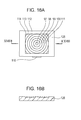
- Figs. 16A and 16B illustrate an example of a Fresnel lens.
- Fig. 16A is a conceptual top view of the Fresnel lens
- Fig. 16B is a conceptual sectional view, taken along line XVIB-XVIB of Fig. 16A .
- the Fresnel lens includes a first zone 97, a second zone 98, a third zone 99, a fourth zone 110, a fifth zone 111, a sixth zone 112, a seventh zone 113, an eighth zone 114, a gate 118, and a frame 126. It is difficult to conduct accurate transfer particularly on the Fresnel lens of Figs. 16A and 16B in which the zones are circular but a molded lens itself is rectangular.
- the zones are circular but the molded lens itself is rectangular, there are a portion where the shape of the zones changes from a circular shape to an arc shape (from 111 to 112) and a portion where the arc shape is further divided into short arc shapes (from 112 to 113). It is considered that moldability differs among the portions where the zone shape is a circular shape, an arc shape, and a short arc shape even in one surface (transfer surface) of the same mold cavity that transfers the shape onto an article to be molded. That is, while the zones that do not interfere with the frame shape are completely circular, when the diameter of the zones increases, the zones are divided by interfere with the frame shape. The interfering zones are cut at ends into an arc shape.
- gas filled in the cavity is dissolved in injected resin.
- Grooves of the circular zones do not include a portion from which the gas escapes, and this promotes dissolution.
- gas is discharged by being pushed out from cut ends of grooves of the arc-shaped zones as the resin flows in, and this hinders dissolution. It is considered that this difference in moldability forms a shape difference between the inner zones and the outer zones. For this reason, in the molded article, streaks sometimes appear in the portion where the zone shape changes from the circular shape to the arc shape and the portion where the zone shape changes from the arc shape to the divided short arc shape.
- the present invention provides a molded-article manufacturing method and a mold that can transfer, on an article to be molded, a homogeneous and high-quality shape on the entire surface of the mold (transfer shape surface) for transferring the shape.
- the present invention in its first aspect provides a molded-article manufacturing method as specified in Claims 1 to 7.
- the present invention in its second aspect provides a mold as specified in Claims 8 to 11.
- the present invention in its third aspect provides an optical element as specified in Claims 12 to 14.
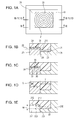
- Figs. 1A to 1E illustrate a first embodiment.
- Figs. 2A to 2C illustrate an optical element (focusing screen) including a Fresnel lens.
- Fig. 3 schematically illustrates an example of a gas-assist injection mold.
- Figs. 4A to 4C illustrate the relationship between a center-portion molding member and a frame-portion molding member.
- Fig. 5 illustrates a modification
- Figs. 6A to 6C illustrate a second embodiment.
- Figs. 7A and 7B illustrate the second embodiment.
- Figs. 8A to 8C illustrate modifications.
- Fig. 9 illustrates a further modification.
- Fig. 10 illustrates a still further modification.
- Fig. 11 illustrates a first example.
- Fig. 12 illustrates a fourth example.
- Fig. 13 illustrates the fourth example.
- Fig. 14 illustrates a sixth example.
- Fig. 15 illustrates a seventh example.
- Figs. 16A and 16B illustrate an optical element (focusing screen) including a Fresnel lens of the related art.
- Figs. 1A to 1E illustrate a molded-article manufacturing method according to a first embodiment of the present invention.
- the molded-article manufacturing method of the first embodiment is suited to manufacture optical elements, particularly, an optical element, such as a Fresnel lens, on which a precise shape should be transferred.
- an optical element such as a Fresnel lens
- a description will be given of a manufacturing method for an optical element (focusing screen) including a Fresnel lens as an example of a molded article.
- FIG. 1A schematically illustrates a part of a cavity.
- a center-portion molding member 21 has a center-portion transfer shape surface 30 on which a transfer shape is engraved to transfer a groove shape of a Fresnel grating or a diffraction grating.
- a frame-portion molding member 38 is provided to surround an outer periphery of the center-portion molding member 21.
- the frame-portion molding member 38 has a frame-portion transfer shape surface 23.
- Figs. 1B to 1D are schematic partial sectional views taken along line IB TO ID-IB TO ID of Fig. 1A.
- Fig. 1E is a schematic partial sectional view taken along line IE-IE of Fig. 1A such that a side face of the center-portion molding member 21 is exposed.
- groove portions 212 continuing from the center-portion transfer shape surface 30 are also formed in a side wall surface 211 of the center-portion molding member 21.
- the side wall surface 211 is cut most deeply (the side wall surface 211 is the lowest).
- the groove portions 212 protrude from the frame-portion transfer shape surface 23.
- a length W of the portion of the side wall surface 211 from the frame-portion transfer shape surface 23 to the groove portions 212 is preferably set to be within the range of 20 to 100 ⁇ m.
- the length W of the portion of the side wall surface 211 from the frame-portion transfer shape surface 23 to the groove portions 212 can be found by dropping a perpendicular 232 from the bottom portions 213 of the groove portions 212 to a plane 231 including the frame-portion transfer shape surface 23 and measuring the distance between the bottom portions 213 and a point 233 where the perpendicular 232 intersects the plane 231.
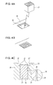
- Figs. 4A to 4C illustrate the relationship between the center-portion molding member 21 and the frame-portion molding member 38.
- the frame-portion molding member 38 may be a die set. While the frame-portion molding member 38 may be movable or stationary, it is preferably movable for easy mold release.
- An insert pocket 24 is provided in the frame-portion molding member (die set) 38 to receive the center-portion molding member 21.
- Fig. 4A illustrates a state before the center-portion molding member 21 is inserted and fitted in the insert pocket 24 of the frame-portion molding member (die set) 38
- Fig. 4B illustrates a state after the center-portion molding member 21 is inserted and fitted in the insert pocket 24.
- Fig. 4A illustrates a state before the center-portion molding member 21 is inserted and fitted in the insert pocket 24 of the frame-portion molding member (die set) 38
- Fig. 4B illustrates a state after the center-portion molding member 21 is inserted and fitted in the insert pocket 24.
- FIG. 4C is a cross-sectional view (including a partial enlarged view) illustrating a state in which the center-portion molding member 21 is inserted and fitted in the insert pocket 24 of the frame-portion molding member (die set) 38.
- Fig. 4C illustrates the center-portion molding member 21, an auxiliary line 22, the frame-portion transfer shape surface 23, the insert pocket 24 of the frame-portion molding member (die set) 38, a clearance 25, an adjusting component 40, a stepped portion 27, and the frame-portion molding member (die set) 38.
- the auxiliary line 22 indicates the positions of the bottom portions 213 of the groove portions 212.
- the adjusting component 40 changes the length W of the portion of the side wall surface 211 between the groove portions 212 and the frame-portion transfer shape surface 23.
- the stepped portion 27 is provided at a mouth of the insert pocket 24 of the frame-portion molding member (die set) 38 to transfer a frame 26 of a Fresnel molded article.
- Drilling is suited to work the center-portion transfer shape surface 30 for transferring a grating shape such as a Fresnel grating. For this reason, it is difficult to directly form the center-portion transfer shape surface 30 on the frame-portion molding member (die set) 38.
- the center-portion molding member 21 is separately formed, and is inserted and fitted in the insert pocket 24 of the frame-portion molding member (die set) 38, whereby an integral mold is obtained.
- the clearance 25 is thereby formed between the center-portion molding member 21 and the frame-portion molding member (die set) 38.
- the clearance 25 is within the range of 10 to 50 ⁇ m.
- Fig. 3 schematically illustrates an example of a gas-assist injection mold, in which a frame-portion molding member is formed by a movable die set.
- melted resin is injected from a cylinder 19 into a cavity 28, which is defined by a center-portion molding member 21, a movable die set 38, and a stationary die set 37, while rotating a screw 20 (a resin injection unit).
- Gas is supplied from a gas supplier 34 to the cavity 28 through a pipe 33 (a gas supply unit).
- Reference numerals 35, 36, 39, and 41 denote a stationary attachment plate, a movable attachment plate, an ejector rod, and an ejector plate, respectively.
- a molded article is thus formed by injecting gas and resin into the cavity 28.
- the center-portion molding member 21 is inserted and fitted in a pocket of the movable die set 38 to form the cavity 28 between the center-portion molding member 21 and the stationary die set 37.
- a pocket may also be formed in the other die set (the stationary die set 37 in Fig. 3 ).
- a molding member having a shape for molding a microlens array may be inserted and fitted in this pocket. This makes it possible to mold an optical element, such as a focusing screen, in which a microlens array is provided on a surface opposite a Fresnel lens.
- gas 31 is injected from the gas supplier 34 into the cavity 28 through the pipe 33, and melted resin 29 is injected from the cylinder 19 into the cavity 28 via a gate while rotating the screw 20.
- the gas 31 may be injected before, simultaneously with, or immediately after injection of the resin 29.
- the gate is formed in the frame-portion molding member 38.
- the length W of the portion of the side wall surface 211 between the groove portions 212 and the frame-portion transfer shape surface 23 is set to be within the range of 20 to 100 ⁇ m.
- the molding condition is different between a zone where the space between the center-portion transfer shape surface and the resin is sealed and the gas is confined in the enclosed space and a zone where sealing is not performed by the resin and the gas is released.
- a width Y of the frame portion is preferably more than a width X of the grooves on the center-portion transfer shape surface 30, more preferably 0.30 mm or more.
- the resin 29 can be preferentially filled in the frame portion. This allows more gas to be confined in the enclosed space 39.
- the resin 29 can be preferentially filled in the frame portion by forming, in the frame-portion molding member 38, the gate serving as an entrance from which the resin 29 is injected into the cavity 29.
- the gas 31 confined in the enclosed space 39 is dissolved in the resin 29 and plasticizes the resin 29.
- the resin 29 is plasticized, it decreases its viscosity.
- a dwelling step is performed.
- the enclosed space 39 is gradually squashed by a predetermined resin pressure, as illustrated in Fig. 1C .
- the center-portion transfer shape is uniformly and accurately transferred thereon. Since the center-portion molding member 21 is sealed with the resin, the gas uniformly acts on the entire center-portion transfer shape surface 30 of the center-portion molding member 21, and transfer is completed.
- This state is illustrated in Figs. 1D and 1E . In this way, a mold structure that allows gas to be uniformly confined on the entire center-portion transfer shape surface 30 can be obtained without forming a separate seal structure. Since all zones are uniformly formed in a molded article thus obtained, no external defect is caused, and the molded article is good.
- the advantage of the present invention is provided even when only one groove portion is provided.
- the length W of the portion of the side wall surface 211 from the frame-portion transfer shape surface 23 to the groove portions 212 is preferably set to be within the range of 20 to 100 ⁇ m.
- the advantage of the present invention is provided in part.
- the sectional shape of the groove portions 212 is not limited to a triangular shape as in the first embodiment, and may be freely determined, for example, may be a curved shape or a polygonal shape.
- Figs. 2A to 2C illustrate an optical element (focusing screen) including a Fresnel lens as an example of a molded article.
- Fig. 2A is a conceptual top view of an optical element (focusing screen) including a Fresnel lens
- Fig. 2B is a conceptual sectional view taken along line IIB-IIB of Fig. 2A.
- Fig. 2C is a conceptual sectional view taken along line IIC-IIC of Fig. 2A .
- the optical element includes a center portion 21' having a polygonal outside shape, and a frame portion 26 surrounding the center portion 21'.
- a grating (zones) is provided in the center portion 21'.
- the zones include a first zone 7, a second zone 8, a third zone 9, a fourth zone 10, a fifth zone 11, a sixth zone 12, a seventh zone 13, and an eighth zone 14.
- Reference numeral 18 denotes the position of a gate
- reference numeral 23' denotes an upper surface of the frame portion 26.
- a Fresnel lens has a zonal structure formed by cutting out a lens surface to form zones and concentrically arranging the zones on a plane, and can be considered as an aggregate of prisms.
- the lens in order for the lens to have sufficient power, the curvature increases and the lens becomes thicker.
- the lens By making the lens into a Fresnel lens, the lens can have a light collecting function while having a flat structure. This achieves compactness and high integration properties.
- flatness unevenness among the inclined faces of the zones can be limited to 10 nm or less by setting a length W' from an intersection 22' of tops of the zones and the frame portion 26 to a flat surface including the upper surface 23' of the frame portion 26 to be within the range of 20 to 100 ⁇ m.
- the length (height difference) W' from the intersection 22' of the tops of the zones and the frame portion 26 to the flat surface including the upper surface 23' of the frame portion 26 is defined as a length of the upper surface 23' of the frame portion 26 from the tops of the zones of the grating.
- Flatness unevenness among the inclined faces can be found as follows. First, several points on the inclined face of each zone of the grating are set as measuring points, flatness is measured for all zones, and the difference between the highest flatness and the lowest flatness is taken as flatness unevenness.
- the optical element including the Fresnel lens is not limited to the focusing screen for a viewfinder of a camera illustrated in Figs. 2A to 2C , and may be, for example, a back-projection screen and a condenser lens in an overhead projector.
- the outside shape of the center portion 21' may be a rectangular shape, a polygonal shape, such as a pentagonal shape illustrated in Fig. 5 , or other shapes.
- the transfer surface of the frame portion 26 does not always need to be flat, and may be a curved surface or may include fine irregularities.
- the frame-portion transfer shape surface is formed on the frame-portion molding member (die set) having the space (insert pocket) that receives the center-portion molding member 21.
- a frame-portion transfer shape surface can be formed on a center-portion molding member.
- Fig. 6A illustrates a center-portion molding member 43 having a side wall surface 42.
- the side wall surface 42 and a frame-portion transfer shape surface 44 are formed on an outer periphery of a center-portion transfer shape surface by forming a cutout on the entire outer edge of a center-portion transfer shape surface 30.
- Figs. 6B and 6C illustrate the relationship between the center-portion molding member 43 and a frame-portion molding member (or a die set) 38.
- Fig. 6B illustrates a state in which the center-portion molding member 43 is assembled in the frame-portion molding member (die set) 38.
- Fig. 6B illustrates the center-portion shaper transfer surface 30, and a gate 45.
- Fig. 6C is a schematic cross-sectional view taken along line VIC-VIC of Fig. 6B (including a partial enlarged view) illustrating a state in which the center-portion molding member 43 is assembled in the frame-portion molding member (die set) 38.
- Fig. 6C illustrates the center-portion molding member 43, the frame-portion transfer shape surface 44 provided on the center-portion molding member 43, and a surface 27 of the frame-portion molding member 38 for transferring an outer wall of a frame portion of a molded article.
- Figs. 7A and 7B illustrate a state in which the center-portion molding member 43 of Figs. 6A to 6C is assembled in the gas-assist injection mold illustrated in Fig. 3 .
- Fig. 7A is a schematic view of a movable die in an open state of the mold, as viewed from a stationary side.
- Fig. 7B schematically illustrates a state in which resin is injected in a cavity together with gas.
- the center-portion molding member 43 has the center-portion transfer shape surface 30 on which a transfer shape for transferring a groove shape of a Fresnel grating is engraved. The entire outer periphery of the center-portion molding member 43 is cut out to form the frame-portion transfer shape surface 44.
- the frame-portion molding member (die set) 38 has a space (insert pocket), and the center-portion molding member 43 is inserted in the pocket.
- a clearance 25 is provided at the boundary between the center-portion molding member 43 and the frame-portion molding member 38.
- Reference numeral 45 denotes a gate.
- Fig. 7B is a schematic partial sectional view taken along line VIIB-VIIB of Fig. 7A .
- resin 29 flows along a frame portion defined by the frame-portion transfer shape surface 44 and the side wall surface 42, which are formed by the cutout portion on the outer periphery of the center-portion transfer shape surface 30, and the frame-portion molding member 38.
- the resin 29 comes into tight contact with the side wall surface 42, and closes a gap between the center-portion transfer shape surface 30 and the resin 29 to form an enclosed space 39, whereby gas is uniformly confined and held on the center-portion transfer shape surface 30.
- This structure can increase the distance from the center-portion transfer shape surface 30 to the clearance 25 provided between the center-portion molding member 43 and the frame-portion molding member (die set) 38. Moreover, when the resin 29 is filled, the gas is confined by two surfaces, that is, the side wall surface 42 and the frame-portion transfer shape surface 44 formed by the cutout portion. Hence, the gas sealing effect on the center-portion transfer shape surface 30 is enhanced, and the quality of a molded article is improved.
- the frame portion of the molded article is formed by the frame-portion molding member (die set)
- the groove portions of the center-portion transfer shape surface to protrude from the frame-portion transfer shape surface
- the length S of the portion of the side wall surface from the frame-portion transfer shape surface to the groove portions is determined by the working amount of the cutout, the effort to produce the mold can be reduced.
- the shape formed by the cutout is not subject to fine restrictions.
- the cutout does not always need to be formed by one step, but may be formed by two or more steps.
- the cutout does not always need to have a right angle, but may be formed by a curved surface.
- the cutout does not always need to have a right angle, but may be rectangular.
- cutout does not always need to be formed all around the periphery of the center-portion transfer shape surface. As illustrated in Fig. 9 , cutouts 42 may be formed on only two of four sides that form the rectangular outline.
- a good molded article can also be obtained by a structure in which a frame portion is formed by transferring shapes of a part of a cutout and a part of a frame-portion molding member (or die set). While a frame-portion transfer shape surface 44 of a center-portion molding member and a frame-portion transfer shape surface 23 of a frame-portion molding member (die set) are flush with each other in Fig. 10 , a height difference may be formed therebetween.
- a focusing screen illustrated in Fig. 11 was molded with the mold adopted in the first embodiment.
- Acrylic resin was used as a resin material, and carbon dioxide was used as gas.
- Carbon dioxide taken in from a liquid carbon dioxide tank by a gas supplier was heated to 50°C and pressurized at 8 MPa, and was injected into a mold in association with a molding machine by being triggered by a signal indicating the screw position in a plasticizing device.
- the molding machine and the gas supplier were connected by an SUS pipe having an inner diameter of 1.6 mm and a length of 5 m.
- the screw diameter was 25 mm
- the thickness D of the focusing screen was 1.3 mm
- a frame was shaped like a rectangle having a longitudinal length N of 29 mm and a lateral length M of 18.5 mm ( Fig. 11 ).
- the width of the frame was 1.9 mm on a short side X, 1.3 mm on a gate-side long side Z, and 0.65 mm on an anti-gate side long side Y.
- the pitch of grating grooves (zones) was 30 ⁇ m, and the depth of the outermost peripheral groove was about 19 ⁇ m.
- the depth unevenness among bottom face portions of the grooves was 1 ⁇ m or less, and the height of a frame-portion transfer shape surface was obtained at an accuracy of ⁇ 1 ⁇ m all around the periphery.
- the mold had one cavity, and a gate was formed by a fan gate having a thickness of 1 mm.
- gas and resin were injected into the cavity at an injection speed of 2 mm/s and a holding pressure of 62.5 MPa. Molding was performed while a length W of a portion of a side wall surface from the groove portions to the frame-portion transfer shape surface was 41.4 ⁇ m. The length W of the portion of the side wall surface from the groove portions to the frame-portion transfer shape surface was adjusted by inserting an adjusting component 40 under a center-portion molding member.
- Molding was performed in a manner similar to that adopted in the first example, except that the length W of the portion of the side wall surface from the groove portions to the frame-portion transfer shape surface in the first example was changed to 6.5 ⁇ m.
- Molding was performed in a manner similar to that adopted in the first example, except that the length W of the side wall surface from the groove portions to the frame-portion transfer shape surface in the first example was changed to 16.8 ⁇ m.
- Molding was performed in a manner similar to that adopted in the first example, except that the position (height) of the groove portions in the first example was changed to be equal to that of the frame-portion transfer shape surface.
- a line shaped like an inscribed circle was clearly recognized in a molded article.
- a focusing screen illustrated in Fig. 12 was molded.
- the thickness D was 1.5 mm, and a frame was shaped like a rectangle having a longitudinal length N of 40 mm and a lateral length M of 28 mm ( Fig. 12 ).
- the pitch of grating grooves was 35 ⁇ m, and the height of the outermost peripheral zone was about 27 ⁇ m.
- the width of the frame was 0.5 mm all around the periphery (X, Y, and Z).
- a mold had two cavities corresponding to the size of a molded article, and a gate was formed by a fan gate having a thickness of 1 mm.
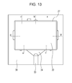
- Fig. 13 schematically illustrates a movable cavity including a runner 33 and a gate 34.
- the depth unevenness among the bottom face portions of the grooves was limited to 1 ⁇ m or less by high-accuracy machining, and the height of the frame-portion transfer shape surface was obtained at an accuracy of ⁇ 1 ⁇ m all around the periphery.
- the protrusion amount (length of the portion of the side wall surface from the groove portions to the frame-portion transfer shape surface) W does not always need to be uniform all around the periphery of the cavity in this way. It is satisfactory as long as the protrusion amount W is within a predetermined range all around the periphery of the cavity.
- Fig. 13 illustrates the positions of seven measuring points around the cavity.
- Table 1 shows protrusion amounts W measured at the measuring points. Although insufficient transfer was found in part, it does not have any influence on the appearance.
- Molding was performed in a manner similar to that adopted in the second example, except that the protrusion amount at a measuring point b in the fourth example was changed to 41 ⁇ m.
- the protrusion amount W was within the range of 20 to 100 ⁇ m at all measuring points. An external defect was not confirmed, and a good molded article was obtained. It is found that it is more preferable to set the protrusion amount W to be at least 20 ⁇ m all around the periphery of the cavity.
- a focusing screen illustrated in Fig. 14 was molded.
- Acrylic resin was used as a resin material, and carbon dioxide was used as gas.
- Carbon dioxide taken in from a liquid carbon dioxide tank by a gas supplier was heated to 50°C and pressurized at 8 MPa, and was injected into a mold in association with a molding machine by being triggered by a signal indicating the screw position in a plasticizing device.
- the molding machine and the gas supplier were connected by an SUS pipe having an inner diameter of 1.6 mm and a length of 5 m.
- the screw diameter was 25 mm
- the thickness D of the focusing screen was 1.3 mm
- a frame was shaped like a rectangle having a longitudinal length N of 29 mm and a lateral length M of 18.5 mm ( Fig. 14 ).
- the width of the frame was 1.9 mm on a short side X, 1.3 mm on a gate-side long side Z, and 0.30 mm on an anti-gate side long side Y.
- the pitch of grating grooves (zones) was 30 ⁇ m, and the depth of the outermost peripheral groove was about 19 ⁇ m.
- the depth unevenness among bottom face portions of the grooves was 1 ⁇ m or less, and the height of a frame-portion transfer shape surface was obtained at an accuracy of ⁇ 1 ⁇ m all around the periphery.
- the mold had one cavity, and a gate was formed by a fan gate having a thickness of 1 mm.
- gas and resin were injected into the cavity at an injection speed of 2 mm/s and a holding pressure of 62.5 MPa. Molding was performed while a length W of a portion of a side wall surface from the groove portions to the frame-portion transfer shape surface was 20 ⁇ m. The length W of the portion of the side wall surface from the groove portions to the frame-portion transfer shape surface was adjusted by inserting an adjusting component 40 under a center-portion molding member. Although a quite faint line shaped like an inscribed circle was found in a molded article, the obtained molded article favorably compared with a good molded article.
- Molding was performed by a method similar to that adopted in the sixth example, except that a focusing screen illustrated in Fig. 15 was molded. Compared with the focusing screen of Fig. 14 , in the focusing screen of Fig. 15 , the width Y of a frame on an anti-gate long side is smaller, that is, 0.10 mm.
- the width of the frame is at least 0.30 mm all around the periphery of the molded article.
- a focusing screen illustrated in Fig. 14 was molded.
- Molding was performed by a method similar to that adopted in the sixth example, except that a frame portion was formed by transferring the side wall surface 42 and the frame-portion transfer shape surface 44 in the center-portion molding member 43 of the second embodiment ( Fig. 6 ).
- the length S of the portion of the side wall surface 42 from the frame-portion transfer shape surface 44 to groove portions was 50 ⁇ m, and the width T of the frame portion was 300 ⁇ m. An external defect was not confirmed, and a good molded article was obtained.
- a center-portion molding member (21) having a center-portion transfer shape surface (30) and a side wall surface (211) is inserted and fitted in a frame-portion molding member (38) having a frame-portion transfer shape surface (23) to form a part of a cavity (28).
- the center-portion molding member (21) has a groove portion (212) in the side wall surface (211). The groove portion (212) protrudes from the frame-portion transfer shape surface (23).
- the side wall surface (211) of the center-portion molding member (21) is sealed with the resin to form, between the center-portion transfer shape surface (30) and the resin, a space (39) in which gas is confined.
Landscapes
- Engineering & Computer Science (AREA)
- Physics & Mathematics (AREA)
- Manufacturing & Machinery (AREA)
- Mechanical Engineering (AREA)
- General Physics & Mathematics (AREA)
- Optics & Photonics (AREA)
- Health & Medical Sciences (AREA)
- Ophthalmology & Optometry (AREA)
- Moulds For Moulding Plastics Or The Like (AREA)
- Injection Moulding Of Plastics Or The Like (AREA)
Applications Claiming Priority (1)
| Application Number | Priority Date | Filing Date | Title |
|---|---|---|---|
| JP2012086502 | 2012-04-05 |
Publications (1)
| Publication Number | Publication Date |
|---|---|
| EP2647480A1 true EP2647480A1 (de) | 2013-10-09 |
Family
ID=48082837
Family Applications (1)
| Application Number | Title | Priority Date | Filing Date |
|---|---|---|---|
| EP13159682.7A Withdrawn EP2647480A1 (de) | 2012-04-05 | 2013-03-18 | Herstellungsverfahren für geformte Gegenstände, Form und optisches Element mit einer Fresnel-Linse |
Country Status (4)
| Country | Link |
|---|---|
| US (2) | US9395470B2 (de) |
| EP (1) | EP2647480A1 (de) |
| JP (1) | JP6108916B2 (de) |
| CN (1) | CN103358490B (de) |
Cited By (4)
| Publication number | Priority date | Publication date | Assignee | Title |
|---|---|---|---|---|
| CN103660174A (zh) * | 2013-12-30 | 2014-03-26 | 哈尔滨固泰电子有限责任公司 | 光学透镜的加工方法 |
| WO2017060417A1 (de) * | 2015-10-09 | 2017-04-13 | Trw Automotive Electronics & Components Gmbh | Linsenbauteil eines regensensors sowie baukastensystem, verfahren und werkzeug zur herstellung |
| CN108127580A (zh) * | 2017-12-13 | 2018-06-08 | 湖北鼎汇微电子材料有限公司 | 一种制备抛光层的模具 |
| WO2021208412A1 (zh) * | 2020-04-13 | 2021-10-21 | 成都菲斯特科技有限公司 | 菲涅尔透镜模具及其制备方法和菲涅尔透镜的制备方法 |
Families Citing this family (4)
| Publication number | Priority date | Publication date | Assignee | Title |
|---|---|---|---|---|
| JP6655294B2 (ja) * | 2015-03-19 | 2020-02-26 | 株式会社デンソーウェーブ | Plc操作装置の樹脂ケース |
| JP2018034314A (ja) * | 2016-08-29 | 2018-03-08 | 株式会社エンプラス | 微細形状転写成形方法、及び微細形状転写成形金型 |
| CN114286742A (zh) * | 2019-07-17 | 2022-04-05 | 艾倍思科技股份有限公司 | 用于形成热塑性制品的模制方法 |
| CN111103640B (zh) * | 2019-11-27 | 2021-11-12 | 诚瑞光学(常州)股份有限公司 | 菲涅尔透镜金属模具制作方法 |
Citations (9)
| Publication number | Priority date | Publication date | Assignee | Title |
|---|---|---|---|---|
| JPS56121748A (en) * | 1980-02-29 | 1981-09-24 | Nissei Plastics Ind Co | Injection molding method |
| EP0139275A1 (de) * | 1983-10-11 | 1985-05-02 | Nissan Motor Co., Ltd. | Leuchteneinrichtung |
| JPH10138305A (ja) * | 1996-09-10 | 1998-05-26 | Asahi Chem Ind Co Ltd | 射出圧縮成形方法 |
| US5840352A (en) * | 1993-09-06 | 1998-11-24 | Fuji Photo Film Co., Ltd. | Fresnel lens manufacturing apparatus |
| EP0914919A1 (de) * | 1997-05-21 | 1999-05-12 | Asahi Kasei Kogyo Kabushiki Kaisha | Verfahren zum spritzgiessen von thermoplastischen kunstharzen |
| JPH11245257A (ja) | 1998-03-02 | 1999-09-14 | Asahi Chem Ind Co Ltd | 熱可塑性樹脂の射出成形法 |
| JP2001047523A (ja) * | 1999-08-10 | 2001-02-20 | Honda Motor Co Ltd | フレネルレンズ用金型及びこの金型を用いたフレネルレンズの製造方法 |
| EP1738887A1 (de) * | 2005-06-29 | 2007-01-03 | Munekata Co. Ltd. | Gasunterstütztes Pressformverfahren |
| JP2007283752A (ja) * | 2006-03-24 | 2007-11-01 | Ricoh Co Ltd | 樹脂成形品の製造方法および製造装置ならびに樹脂成形品 |
Family Cites Families (13)
| Publication number | Priority date | Publication date | Assignee | Title |
|---|---|---|---|---|
| US2831394A (en) * | 1952-08-22 | 1958-04-22 | Elastic Stop Nut Corp | Catadioptric lenses |
| US4170616A (en) * | 1978-05-30 | 1979-10-09 | Rca Corporation | Method of fabrication of a Fresnel lens |
| JPH0673860B2 (ja) * | 1985-07-16 | 1994-09-21 | パイオニア株式会社 | フレネルレンズ製作用金型 |
| JPH0772312A (ja) * | 1993-09-06 | 1995-03-17 | Fuji Photo Film Co Ltd | フレネルレンズの製造装置と製造方法 |
| JPH08136708A (ja) * | 1994-11-11 | 1996-05-31 | Sony Corp | フレネルレンズ製造方法 |
| TW429213B (en) * | 1996-09-03 | 2001-04-11 | Asahi Chemical Ind | Method for molding thermoplastic resin |
| JP3875587B2 (ja) * | 1996-09-03 | 2007-01-31 | 旭化成ケミカルズ株式会社 | 熱可塑性樹脂のガスアシスト射出成形法 |
| JP2001318430A (ja) * | 2000-05-10 | 2001-11-16 | Kuraray Co Ltd | 背面投射型スクリーン |
| US7794643B2 (en) | 2006-03-24 | 2010-09-14 | Ricoh Company, Ltd. | Apparatus and method for molding object with enhanced transferability of transfer face and object made by the same |
| JP5045221B2 (ja) * | 2007-05-07 | 2012-10-10 | 三菱瓦斯化学株式会社 | 金型組立体、及び、射出成形方法 |
| TWI431328B (zh) * | 2008-12-26 | 2014-03-21 | Canon Kk | 菲涅耳透鏡和射出成型 |
| JP2011151218A (ja) * | 2010-01-22 | 2011-08-04 | Stanley Electric Co Ltd | 発光装置 |
| US9242418B2 (en) * | 2011-11-16 | 2016-01-26 | Essilor International | Ophthalmic lens containing a fresnel surface and method for manufacturing same |
-
2013
- 2013-03-14 US US13/804,200 patent/US9395470B2/en not_active Expired - Fee Related
- 2013-03-18 EP EP13159682.7A patent/EP2647480A1/de not_active Withdrawn
- 2013-04-02 JP JP2013077130A patent/JP6108916B2/ja not_active Expired - Fee Related
- 2013-04-03 CN CN201310113542.5A patent/CN103358490B/zh not_active Expired - Fee Related
-
2016
- 2016-06-17 US US15/186,111 patent/US20160297156A1/en not_active Abandoned
Patent Citations (9)
| Publication number | Priority date | Publication date | Assignee | Title |
|---|---|---|---|---|
| JPS56121748A (en) * | 1980-02-29 | 1981-09-24 | Nissei Plastics Ind Co | Injection molding method |
| EP0139275A1 (de) * | 1983-10-11 | 1985-05-02 | Nissan Motor Co., Ltd. | Leuchteneinrichtung |
| US5840352A (en) * | 1993-09-06 | 1998-11-24 | Fuji Photo Film Co., Ltd. | Fresnel lens manufacturing apparatus |
| JPH10138305A (ja) * | 1996-09-10 | 1998-05-26 | Asahi Chem Ind Co Ltd | 射出圧縮成形方法 |
| EP0914919A1 (de) * | 1997-05-21 | 1999-05-12 | Asahi Kasei Kogyo Kabushiki Kaisha | Verfahren zum spritzgiessen von thermoplastischen kunstharzen |
| JPH11245257A (ja) | 1998-03-02 | 1999-09-14 | Asahi Chem Ind Co Ltd | 熱可塑性樹脂の射出成形法 |
| JP2001047523A (ja) * | 1999-08-10 | 2001-02-20 | Honda Motor Co Ltd | フレネルレンズ用金型及びこの金型を用いたフレネルレンズの製造方法 |
| EP1738887A1 (de) * | 2005-06-29 | 2007-01-03 | Munekata Co. Ltd. | Gasunterstütztes Pressformverfahren |
| JP2007283752A (ja) * | 2006-03-24 | 2007-11-01 | Ricoh Co Ltd | 樹脂成形品の製造方法および製造装置ならびに樹脂成形品 |
Cited By (5)
| Publication number | Priority date | Publication date | Assignee | Title |
|---|---|---|---|---|
| CN103660174A (zh) * | 2013-12-30 | 2014-03-26 | 哈尔滨固泰电子有限责任公司 | 光学透镜的加工方法 |
| WO2017060417A1 (de) * | 2015-10-09 | 2017-04-13 | Trw Automotive Electronics & Components Gmbh | Linsenbauteil eines regensensors sowie baukastensystem, verfahren und werkzeug zur herstellung |
| CN108127580A (zh) * | 2017-12-13 | 2018-06-08 | 湖北鼎汇微电子材料有限公司 | 一种制备抛光层的模具 |
| CN108127580B (zh) * | 2017-12-13 | 2019-09-13 | 湖北鼎汇微电子材料有限公司 | 一种制备抛光层的模具 |
| WO2021208412A1 (zh) * | 2020-04-13 | 2021-10-21 | 成都菲斯特科技有限公司 | 菲涅尔透镜模具及其制备方法和菲涅尔透镜的制备方法 |
Also Published As
| Publication number | Publication date |
|---|---|
| JP2013230672A (ja) | 2013-11-14 |
| US20130265655A1 (en) | 2013-10-10 |
| CN103358490B (zh) | 2016-06-01 |
| JP6108916B2 (ja) | 2017-04-05 |
| US9395470B2 (en) | 2016-07-19 |
| US20160297156A1 (en) | 2016-10-13 |
| CN103358490A (zh) | 2013-10-23 |
Similar Documents
| Publication | Publication Date | Title |
|---|---|---|
| US9395470B2 (en) | Molded-article manufacturing method, mold, and optical element including fresnel lens | |
| KR101093456B1 (ko) | 수지성형장치 및 수지성형방법 | |
| KR100517914B1 (ko) | 사출압축 성형장치 및 사출압축 성형방법 | |
| JP2000084945A (ja) | プラスチック成形品およびその成形方法 | |
| US20100102465A1 (en) | Plastic lens molding method | |
| US8603382B2 (en) | Plastics molding system and optical element formed by the same | |
| JP2686122B2 (ja) | プラスチックレンズの高精度成形方法及びその成形装置 | |
| JP2006281765A (ja) | 光学素子の表面精度改善方法及びその装置 | |
| KR20050004050A (ko) | 수지 정립 렌즈 어레이 및 이의 제조방법 | |
| JP3706169B2 (ja) | 射出成形用金型 | |
| US20140055868A1 (en) | Plastic Lens with Improved Eccentricity and Method for Manufacturing the Same | |
| JPH06238711A (ja) | プラスチックの射出成形方法および装置 | |
| JPH09309156A (ja) | 光学部品の成形方法及び成形型及び光学部品 | |
| JP2008238687A (ja) | 金型装置と射出成形方法、及び光学素子 | |
| JP2014162012A (ja) | 微細構造体成形方法及び微細構造体成形金型 | |
| US20060269646A1 (en) | Molding metal mold and method for producing the molding metal mold | |
| JP2004041776A (ja) | 合成樹脂製注射器シリンダ | |
| JP7074047B2 (ja) | 樹脂部品の製造方法 | |
| JP4695485B2 (ja) | 成形用金型および成形方法 | |
| JP2004025817A (ja) | 導光板の製造方法 | |
| JP2002225095A (ja) | 合成樹脂製注射器シリンダの射出成形用金型及び成形方法並びに合成樹脂製注射器シリンダ | |
| JP3135387B2 (ja) | 鏡筒付光学素子およびその製造方法 | |
| JPH0421611B2 (de) | ||
| TWI438516B (zh) | 組合鏡片及其製造設備、製造方法 | |
| JP4766264B2 (ja) | 光学素子の製造方法、インサート部材及び光学素子 |
Legal Events
| Date | Code | Title | Description |
|---|---|---|---|
| PUAI | Public reference made under article 153(3) epc to a published international application that has entered the european phase |
Free format text: ORIGINAL CODE: 0009012 |
|
| AK | Designated contracting states |
Kind code of ref document: A1 Designated state(s): AL AT BE BG CH CY CZ DE DK EE ES FI FR GB GR HR HU IE IS IT LI LT LU LV MC MK MT NL NO PL PT RO RS SE SI SK SM TR |
|
| AX | Request for extension of the european patent |
Extension state: BA ME |
|
| 17P | Request for examination filed |
Effective date: 20140318 |
|
| RBV | Designated contracting states (corrected) |
Designated state(s): AL AT BE BG CH CY CZ DE DK EE ES FI FR GB GR HR HU IE IS IT LI LT LU LV MC MK MT NL NO PL PT RO RS SE SI SK SM TR |
|
| STAA | Information on the status of an ep patent application or granted ep patent |
Free format text: STATUS: THE APPLICATION HAS BEEN WITHDRAWN |
|
| 18W | Application withdrawn |
Effective date: 20180620 |