EP2647543B1 - Système de détection de caractéristiques de véhicules ferroviaires passant - Google Patents
Système de détection de caractéristiques de véhicules ferroviaires passant Download PDFInfo
- Publication number
- EP2647543B1 EP2647543B1 EP13001672.8A EP13001672A EP2647543B1 EP 2647543 B1 EP2647543 B1 EP 2647543B1 EP 13001672 A EP13001672 A EP 13001672A EP 2647543 B1 EP2647543 B1 EP 2647543B1
- Authority
- EP
- European Patent Office
- Prior art keywords
- sensor
- measuring unit
- load
- rail
- unit
- Prior art date
- Legal status (The legal status is an assumption and is not a legal conclusion. Google has not performed a legal analysis and makes no representation as to the accuracy of the status listed.)
- Active
Links
Images


Classifications
-
- B—PERFORMING OPERATIONS; TRANSPORTING
- B61—RAILWAYS
- B61K—AUXILIARY EQUIPMENT SPECIALLY ADAPTED FOR RAILWAYS, NOT OTHERWISE PROVIDED FOR
- B61K9/00—Railway vehicle profile gauges; Detecting or indicating overheating of components; Apparatus on locomotives or cars to indicate bad track sections; General design of track recording vehicles
- B61K9/04—Detectors for indicating the overheating of axle bearings and the like, e.g. associated with the brake system for applying the brakes in case of a fault
-
- B—PERFORMING OPERATIONS; TRANSPORTING
- B61—RAILWAYS
- B61L—GUIDING RAILWAY TRAFFIC; ENSURING THE SAFETY OF RAILWAY TRAFFIC
- B61L1/00—Devices along the route controlled by interaction with the vehicle or train
- B61L1/20—Safety arrangements for preventing or indicating malfunction of the device, e.g. by leakage current, by lightning
Definitions
- the present invention relates to a system for detecting characteristics of passing rail vehicles on a rail track, wherein at least one measuring unit is provided for measuring the temperature of wheelsets of a passing rail vehicle.
- the document DE 4 217 681 describes a Radsatzdiagnose adopted for monitoring of passing railway vehicles, are housed in the deflecting units and infrared receiver units in a hollow sleeper.
- acceleration sensors are provided on the rails extending above the sleepers, which determine the wheel pressure and / or acceleration values of a wheel passing over them.
- DE 103 05 470 A1 a measuring section for recording different physical quantities of rail-bound vehicles.
- the measuring section has force transducers, temperature sensors and magnetic field sensors which are arranged on rails or sleepers. Furthermore, an evaluation device is provided, with which the temperature sensor and the force transducer are connected.
- the document DE 103 05 470 A1 also discloses that the evaluation device from the signals of the temperature sensor characteristic values for a thermal load of predetermined parts of vehicles crossing over of rail parts and / or surrounding areas.
- the document DE 10 2007 044 796 A1 discloses a measurement method for the determination of emissions, in addition to the measurement of the position of the rail vehicle and the emissions corresponding physical and / or chemical parameter values and meteorological measurement data such.
- an inductive wheel sensor is arranged on a rail.
- a temperature sensor for measuring the rail temperature is attached on the opposite rail.
- a horizontal accelerometer and a vertical accelerometer are arranged.
- a threshold with a provided vertical accelerometer is arranged.
- the physical parameters recorded are the sound pressure level, the rail acceleration, the threshold acceleration, subsurface vibrations or charge-related physical parameters.
- the position of the rail vehicle on the track body is determined by detecting the individual rail vehicle axles.
- the document WO 00/73118 A1 discloses a railroad wheel monitoring apparatus having force sensors integrated with a rail support plate. Downstream of the force sensors are preamplifiers, which in turn are connected to a signal analyzer.
- the document DE 10 2009 024 506 A1 discloses a method for determining maintenance information regarding an object to be serviced.
- a state deterioration model of the object to be serviced is determined on the basis of at least one influencing variable characterizing the state deterioration of the object, and then a maintenance information is determined as a function of this state deterioration model.
- Influencing variables which characterize the state deterioration of the object may be the load, the weather or, in the case of vehicle-side objects, such as a locomotive, the speed.
- the state deterioration model is determined, which models the state deterioration of the object as a function of the corresponding influencing variables.
- the condition degradation model must be validated with periodic measurements so that it can be determined whether the model is associated with actual wear or deviates from actual wear.
- a state-deterioration model for an object is modeled on the basis of an influencing variable.
- the condition degradation model must be checked for accuracy with actual wear measurements. If the condition deterioration model does not match reality, then the model needs to be revised or, in the worst case scenario, a new model identified.
- an IR receiving unit is provided in a closable housing, which is inserted into a recess of a measuring or hollow threshold.
- the housing is supported by attenuators on the top of the threshold.
- an acceleration sensor is arranged on the housing, which is connected to an evaluation unit. Based on the acceleration values of the housing with the IR receiving units detected by the acceleration sensor, the state of the attenuators is determined.
- measuring units for measuring the temperature of wheelsets of passing rail vehicles are of the highest relevance for the safety of rail traffic, there is a need to be able to monitor the measuring units for temperature measurement holistically.
- the system for detecting characteristics of passing rail vehicles has at least one load sensor which detects the mechanical loads acting on the at least one measuring unit and at least one further sensor which provides at least one internal state value of the at least one measuring unit.
- the at least one load sensor and the at least one further sensor are connected to an evaluation unit.
- the evaluation unit is designed to determine at least one value representing the load state of the at least one measuring unit.
- the system according to the invention detects the mechanical load values exerted by the passing or system-passing rail vehicles on the thresholds provided with the at least one measuring unit on the other hand, an internal state value of the measuring unit.
- a value is determined by the evaluation unit, which reflects the load condition of the at least one measuring unit.
- the at least one measuring unit can be monitored holistically on the basis of the determined load value.
- the mechanical load values exerted by the passing rail vehicles on the threshold can be detected, for example, as acceleration values, but also as compressive forces.
- the system according to the invention does not model a state deterioration model which has to be calibrated with the actual wear and tear over intervals.
- a value representing the load state of the at least one measuring unit is continuously determined from the values detected by the at least one mechanical load sensor and the at least one further sensor, which indicates to which loads the at least one measuring unit was actually exposed.
- the evaluation unit which reflects the load status of the at least one measuring unit, it can be determined whether there is a need for maintenance at the measuring unit or an exchange of the entire measuring unit is necessary. Furthermore, it is possible, depending on the determined value for the load condition of the measuring unit, to preventively replace individual components during factory overhauls or repairs.
- the state of the entire measuring unit can be monitored, ie the measuring unit itself is monitored and not only its associated attenuators.
- the inspection intervals for the measuring unit can be adapted to the value determined by the evaluation unit for the load condition of the at least one measuring unit, because loaded freight cars exert considerable higher mechanical loads on the rails, sleepers and thus on the measuring device as light passenger carriages. If the determined value for the load condition is relatively high, for example in the case of rail wagons with relatively high freight traffic, the inspection intervals of the at least one measuring unit can be shortened. On the other hand, in the case of railways with relatively little freight traffic and concomitantly lower loads, the inspection intervals can be extended on the basis of the value determined by the evaluation unit, without endangering the safety of passing rail vehicles or rail traffic.
- the system for detecting the at least one inner state value, comprises at least one further sensor.
- the system may therefore comprise, as a further sensor, at least one temperature sensor which detects the temperature of the at least one measuring unit.
- the system may comprise as a further sensor at least one humidity sensor, which detects the humidity in the at least one measuring unit.
- the system according to the invention may also comprise combinations of sensors which detect different internal state values of the at least one measuring unit.
- the system has both the temperature sensor and the air humidity sensor.
- the temperature of the measuring unit and also the air humidity in the measuring unit flow into the value determined by the evaluation unit for the load state of the at least one measuring unit. Due to the presence of a plurality of sensors for detecting internal state values of the measuring unit, the value determined by the evaluation unit gains information about the integrated loading state of the measuring unit.
- the system may include a sensor for axle counting the passing rail vehicles.
- the mechanical load values detected by the at least one load sensor can be compared with the number of axles of the rail vehicles passing over the system.
- the load of the system or at least one measuring unit per wheel or per axle of the rail vehicle can be determined, so that an accurate load profile for the measuring unit can be generated.
- the values acquired with a system according to this embodiment thus also include measured values which are relevant to the operators of railway lines, such as B. on the axle load of the axes of passing or passing rail vehicles and on the state of the wheels of the axles of passing rail vehicles.
- a detailed load profile of the at least one measuring unit for measuring the temperature of the wheel sets can be determined with the aid of the above-described sensor for axle counting of the rail vehicles, taking into account the axes passing over the system.
- the at least one load sensor can be arranged on the threshold or on at least one rail.
- the at least one load sensor can also be arranged in the threshold. This further simplifies the structure of the system.
- the mechanical load values for all measuring units in the threshold can be determined with the at least one load sensor. Accordingly, only one load sensor is required per load measurement per threshold provided with a measuring unit.
- the at least one strain sensor may be used to detect an approaching train according to one embodiment.
- the load sensor detects the structure-borne sound signals transmitted by the at least one rail or threshold, which are triggered by the approaching rail vehicle.
- the load values detected by the at least one load sensor which arise as a result of the structure-borne sound waves transmitted by the rail, an approaching rail vehicle can be determined and the measuring unit can be put into an active state from an inactive state.
- the at least one load sensor may be an acceleration sensor or a force sensor.
- the at least one strain sensor may be a piezoelectric sensor, magnetic inductive sensor, micro-mechanical sensor, strain gauge, or fiber optic sensor, e.g. as an optical fiber printing plate or an optical fiber bending beam, be formed.
- the preferred location for the load sensor will also change, i. in the threshold, at the threshold or at the rail.
- Piezoelectric sensors, magnetic-inductive sensors and micro-mechanical sensors are preferably arranged at or in the threshold.
- the aforementioned sensor types can also be arranged on a ribbed plate, which serves to connect the threshold with at least one rail.
- Strain gauges are glued directly to the rail or to a claw located on the rail foot.
- An optical fiber pressure plate is preferably disposed between the rail and the fin plate.
- an optical fiber bending beam is preferably arranged on the rail and fastened via a clamp attachment to the foot of the rail in the threshold compartment in front of or behind the threshold with the at least one measuring unit.
- a strain gauge an optical fiber pressure plate or an optical fiber pressure plate or a fiber optic bending beam is selected as the acceleration sensor, only two load sensors are needed to measure the load values of all measuring units at the threshold, with which the relevant values for the rail operators Axle load or over the condition of the wheels of each axle could supply.
- the system may comprise a plurality of force sensors, which are connected to the evaluation unit.
- the plurality of force sensors can be designed and arranged such that they serve both to detect the mechanical loads acting on the threshold and to locate flats on the wheels of the passing rail vehicles, thereby further simplifying the system according to the invention. It is further it is possible for the plurality of force sensors to be used in conjunction with at least one load sensor that measures the mechanical loads of the threshold, with the majority of the force sensors serving for flat location on the wheels of the rail vehicles. In this case, the plurality of force sensors may be arranged adjacent to the threshold provided with the at least one measuring device.
- the same infrastructure can be used for the majority of force sensors as for the measuring unit for temperature measurement of the wheelsets, since the same evaluation unit with the interfaces for communication with the individual sensors and also the same power supply can be used , With a system extended by the majority of force sensors for detecting the properties of passing rail vehicles, it is possible to dispense with a separate and additional system for flat location detection.
- the at least one measuring device can be connected to a threshold or rail via at least one rubber damper, via at least one spring or at least one hydraulic damper.
- the at least one measuring device may comprise an infrared sensor according to an embodiment of the invention.
- the infrared sensor may comprise at least one closure lid according to an embodiment of the invention.
- the system according to this embodiment may comprise as a further sensor a sensor which detects the movement, in particular the movement times, of the at least one closure lid.
- a closure lid is to be understood as a type of protective flap which can close or open a beam path for the infrared radiation of the infrared sensor. If the protective flap or lid is closed, no dirt or similar can get into the measuring unit or the infrared sensor. If the system determines that a rail vehicle is approaching, the closure lid is opened and the infrared sensor is placed in an active state in order to be able to detect the temperature of the wheelsets of the rail vehicle.
- the sensor which detects the movement or the movement times of the closure lid, it is thus possible to detect another internal status value of the measuring unit which provides information on how long the infrared sensor or the measuring unit was in an active state or in an inactive state.
- the evaluation unit may comprise at least one non-volatile memory according to an embodiment of the invention. With the at least one non-volatile memory and the value determined by the evaluation unit for the loading state of the measuring unit, a service life load of the measuring unit can be determined.
- the measuring unit is equipped with a non-volatile memory, wherein the evaluation unit can write in cyclic intervals the value for the load condition and other data in the non-volatile memory of the measuring unit.
- the non-volatile memory of the measuring unit thus stores the values for the load condition or the service life of the measuring unit.
- the load values from the non-volatile memory of the measuring unit can be called up at any time by an evaluation unit.
- the measuring unit is removed from the rail track for maintenance or repair and is usually repaired by the manufacturer.
- the individual measuring units may have been located at different locations during their time of use or have been assigned to different evaluation units or have also been unused in a spare parts store.
- the non-volatile memory of the measuring unit With the non-volatile memory of the measuring unit, the values for the load and also the service life of the measuring unit can be requested by the manufacturer at each repair, even if the at least one measuring unit was connected to different evaluation units at different places of use. In addition to a corrective repair, preventative maintenance of loaded individual parts of the measuring unit can take place as a result.
- both the evaluation unit and the at least one measuring unit have a non-volatile memory, a cyclic exchange of the memory contents between the evaluation unit and the measuring unit can take place.
- the evaluation unit and the at least one measuring unit can be connected to one another such that the at least one measuring unit and the evaluation unit have mutual access to the memory contents in the non-volatile memories of the respective other unit.
- the measuring unit can record in its non-volatile memory how long it has been installed at a specific installation location and which exposure value it has been subjected to by the evaluation unit.
- the evaluation unit can record which measuring unit has been connected in a certain position for how long. In this case, the evaluation unit can also determine a cumulative load value for all the measuring units connected to it and, if exceeding predetermined limit values, issue maintenance messages.
- the evaluation unit can also take into account data, such as the place of use, time of use, load values, and the cumulative load from the non-volatile memory of the at least one measuring unit in its evaluations, which are written in the non-volatile memory of the measuring unit at earlier locations of the measuring unit were.
- the new evaluation unit can retrieve the various data from the non-volatile memory of the at least one measuring unit connected to it and, so to speak, update itself.
- the storage time in days, the number of axes traversing the system, the average of the acceleration values, the average of the air humidity, the average of the internal temperature of the measuring unit and the mechanical loads of the measuring unit over time can be stored in the memory.
- the at least one evaluation unit may be designed such that it determines the state of the value representing at least one measuring unit over a predetermined period of time by means of a predetermined evaluation algorithm.
- the at least one measuring unit can be arranged on at least one threshold or on at least one rail.
- the measuring unit can be at least partially received in a threshold or connected via a holder with at least one rail.
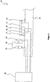
- Fig. 1 shows a schematic view of a first embodiment of the system 10 for detecting characteristics of passing rail vehicles.
- Fig. 1 one recognizes the measuring unit 12 for temperature measurement of wheelsets passing by rail vehicles (not shown), which is connected via attenuators 14, 16 with the threshold 18 and partially received in the threshold 18.
- the measuring unit 12 is an infrared sensor (not shown) which receives the temperature of the wheelsets.
- a threshold 18 between two and eight measuring units 12 are provided to monitor all wheelsets of passing rail vehicles.
- a rail path is generally formed of two rails and a plurality of sleepers 18.
- the load sensor 22 is an acceleration sensor which detects the mechanical loads applied to the threshold 18 by the passing rail vehicles in the form of acceleration values.
- a temperature sensor 26 and an air humidity sensor 28 for detecting the temperature and the air humidity are provided as internal state values of the measuring unit 12.
- the acceleration sensor 22, the axle counting sensor 24, the temperature sensor 26 and the air humidity sensor 28 are connected to an evaluation unit 30. Based on the internal status values of the measuring unit 12 detected by the acceleration sensor 22 and the axle counting sensor 24 and by the temperature sensor 26 and the air humidity sensor 28, the evaluation unit 30 determines a value representing the load condition of the at least one measuring unit.
- FIG. 2 show only slightly modified embodiments of the system 10, wherein according to FIG. 2 the acceleration sensor 22 at the threshold 18 and according to FIG. 3 is arranged in the threshold 18.
Landscapes
- Engineering & Computer Science (AREA)
- Mechanical Engineering (AREA)
- Automation & Control Theory (AREA)
- Force Measurement Appropriate To Specific Purposes (AREA)
- Machines For Laying And Maintaining Railways (AREA)
Claims (15)
- Système (10) de détection de caractéristiques de véhicules ferroviaires roulant sur une voie ferrée, au moins une unité de mesure (12) étant prévue pour mesurer la température de jeux de roues d'un véhicule ferroviaire roulant, caractérisé en ce qu'il est prévu au moins un capteur de sollicitation (22) servant à détecter les sollicitations mécaniques agissant sur ladite au moins une unité de mesure (12) pour surveiller cette dernière, et au moins un capteur supplémentaire (26, 28) servant à fournir au moins une valeur d'état interne de ladite au moins une unité de mesure (12), ledit au moins un capteur de sollicitation (22) et ledit au moins un capteur supplémentaire (26, 28) étant reliés à une unité d'évaluation (30) qui est conçue pour déterminer au moins une valeur représentant l'état de sollicitation de ladite au moins une unité de mesure (12), et ladite au moins une unité de mesure (12) comprenant au moins une mémoire non volatile.
- Système (10) selon la revendication 1,
caractérisé en ce que le système (10) comprend comme capteur supplémentaire au moins un capteur de température (26) qui détecte la température de ladite au moins une unité de mesure (12). - Système (10) selon la revendication 1 ou 2,
caractérisé en ce que le système (10) comprend comme capteur supplémentaire au moins un capteur d'humidité d'air (28) qui détecte l'humidité de l'air dans ladite au moins une unité de mesure (12). - Système (10) selon l'une des revendications 1 à 3,
caractérisé en ce que le système (10) comprend au moins un capteur (24) servant à compter les essieux des véhicules ferroviaires roulants. - Système (10) selon l'une des revendications 1 à 4,
caractérisé en ce que ledit au moins un capteur de sollicitation (22) peut être disposé sur au moins sur une traverse (18) ou sur au moins un rail (20). - Système (10) selon l'une des revendications 1 à 4,
caractérisé en ce que ledit au moins un capteur de sollicitation (22) peut être disposé dans la traverse (18). - Système (10) selon la revendication 5 ou 6,
caractérisé en ce que ledit au moins un capteur de sollicitation (22) peut être utilisé pour la détection d'un véhicule ferroviaire qui s'approche. - Système (10) selon l'une des revendications 1 à 7,
caractérisé en ce que ledit au moins un capteur de sollicitation (22) consiste en un capteur d'accélération ou un capteur d'effort. - Système (10) selon l'une des revendications 1 à 8,
caractérisé en ce que ledit au moins un capteur de sollicitation (22) se présente sous la forme d'un capteur piézoelectrique, d'un capteur magnéto-inductif, d'un capteur micromécanique, d'une bande de mesure d'allongement, d'un capteur à fibres optiques. - Système (10) selon l'une des revendications 1 à 9,
caractérisé en ce que le système (10) comprend une pluralité de capteurs d'effort qui sont reliés à l'unité d'évaluation (30). - Système (10) selon l'une des revendications 1 à 10,
caractérisé en ce que ladite au moins une unité de mesure (12) est disposée sur au moins une traverse ou sur au moins un rail (20), ladite au moins une unité de mesure (12) pouvant être reliée à une traverse (18) ou à un rail (20) par le biais d'au moins un amortisseur en caoutchouc (14, 16), par le biais d'au moins un ressort ou par le biais d'au moins un amortisseur hydraulique. - Système (10) selon l'une des revendications précédentes,
caractérisé en ce que ladite au moins une unité de mesure (12) comprend un capteur infrarouge, le capteur infrarouge présentant au moins un couvercle de fermeture mobile et le système (10) comprenant un capteur qui détecte le mouvement, plus particulièrement les temps de mouvement dudit au moins un couvercle de fermeture. - Système (10) selon l'une des revendications 1 à 12,
caractérisé en ce que l'unité d'évaluation (30) comprend au moins une mémoire non volatile. - Système (10) selon la revendication 13,
caractérisé en ce que l'unité d'évaluation (30) et ladite au moins une unité de mesure (12) sont reliées l'une à l'autre de sorte que ladite au moins une unité de mesure (12) et l'unité d'évaluation (30) ont réciproquement accès aux contenus sauvegardés dans les mémoires non volatiles de chaque autre unité (12 ou 30). - Système (10) selon l'une des revendications 1 à 14,
caractérisé en ce que ladite au moins une unité d'évaluation (30) est conçue de sorte qu'elle calcule sur la base d'un algorithme d'évaluation prédéfini la valeur représentant l'état de sollicitation de ladite au moins une unité de mesure (12) pendant une période prédéterminée.
Applications Claiming Priority (1)
| Application Number | Priority Date | Filing Date | Title |
|---|---|---|---|
| DE102012006844A DE102012006844A1 (de) | 2012-04-04 | 2012-04-04 | System zur Erfassung von Eigenschaften vorbeifahrender Schienenfahrzeuge |
Publications (3)
| Publication Number | Publication Date |
|---|---|
| EP2647543A1 EP2647543A1 (fr) | 2013-10-09 |
| EP2647543B1 true EP2647543B1 (fr) | 2017-03-01 |
| EP2647543B2 EP2647543B2 (fr) | 2020-08-12 |
Family
ID=48087343
Family Applications (1)
| Application Number | Title | Priority Date | Filing Date |
|---|---|---|---|
| EP13001672.8A Active EP2647543B2 (fr) | 2012-04-04 | 2013-04-02 | Système de détection de caractéristiques de véhicules ferroviaires passant |
Country Status (3)
| Country | Link |
|---|---|
| EP (1) | EP2647543B2 (fr) |
| DE (1) | DE102012006844A1 (fr) |
| ES (1) | ES2620830T5 (fr) |
Families Citing this family (5)
| Publication number | Priority date | Publication date | Assignee | Title |
|---|---|---|---|---|
| DE102017122774A1 (de) | 2017-09-29 | 2019-04-04 | fos4X GmbH | Verfahren und System zur Überwachung von Gleissystemen |
| CN107719413B (zh) * | 2017-10-10 | 2019-03-22 | 上海应用技术大学 | 基于磁记忆检测技术的列车轮对踏面故障检测装置及方法 |
| US10894551B2 (en) | 2018-09-05 | 2021-01-19 | Protran Technology, Llc | Lateral rail measurement device |
| DE102020127311A1 (de) | 2020-10-16 | 2022-04-21 | BEN-INNOVA Systemtechnik GmbH | Vorrichtung zur Festbrems- und/oder Heißläuferortung bei Schienenfahrzeugen und System mit einer Vorrichtung zur Festbrems- und/oder Heißläuferortung und zumindest einer Schwelle zur Auflage von Schienen |
| DE102024127484A1 (de) * | 2024-09-23 | 2026-03-26 | Pintsch Gmbh | Anordnung und Verfahren zur Erkennung möglicher Positionierungsprobleme für an einer Fahrzeugschiene angebrachte Geräte und Gerätehalterungen |
Citations (10)
| Publication number | Priority date | Publication date | Assignee | Title |
|---|---|---|---|---|
| DE4217681C2 (de) | 1992-05-29 | 1994-06-23 | Gerd R Dipl Ing Wetzler | Radsatzdiagnoseeinrichtung zur Überwachung vorbeifahrender Eisenbahnfahrzeuge |
| WO2000073118A1 (fr) | 1999-05-28 | 2000-12-07 | Digi Sens Ag | Dispositif de surveillance destine a des roues de vehicules ferroviaires |
| DE10060380A1 (de) | 2000-12-05 | 2002-06-13 | Ge Harris Harmon Railway Techn | Verfahren und Vorrichtung zur Heißläufer- und Festbremsortung |
| WO2004008067A1 (fr) | 2002-07-16 | 2004-01-22 | Aea Technology Plc | Inspection de vehicules ferroviaires |
| DE10305470A1 (de) | 2003-02-13 | 2004-08-26 | Schenck Process Gmbh | Meßstrecke zur Erfassung unterschiedlicher physikalischer Größen schienengebundener Fahrzeuge |
| DE102004021550A1 (de) | 2004-05-03 | 2004-10-21 | Daimlerchrysler Ag | Verfahren zur Ermittlung von Überbeanspruchungen eines Fahrzeugfahrwerks |
| DE102007044796A1 (de) | 2006-09-19 | 2008-03-27 | Kalivoda, Manfred T., Dr. | Messverfahren zur Bestimmung von Emissionen |
| EP1772342B1 (fr) | 2005-10-07 | 2008-12-17 | Bernd Neuroth | Dispositif de surveillance de la température de boîtes d'essieux |
| EP1839990B1 (fr) | 2006-03-31 | 2009-08-05 | Bernd Neuroth | Dispositif pour la vérification des roues d'un véhicule ferroviaire |
| DE102009024506A1 (de) | 2009-06-08 | 2010-12-09 | Deutsches Zentrum für Luft- und Raumfahrt e.V. | Verfahren zur Ermittlung von Wartungsinformationen |
Family Cites Families (3)
| Publication number | Priority date | Publication date | Assignee | Title |
|---|---|---|---|---|
| DE102005024852B4 (de) * | 2005-05-27 | 2018-06-28 | Progress Rail Inspection & Information Systems Gmbh | Vorrichtung zum Erfassen von heißlaufenden Fahrwerkselementen an vorbeifahrenden Schienenfahrzeugen |
| DE102007058993A1 (de) * | 2007-12-07 | 2009-06-10 | General Electric Co. | Vorrichtung zum berührungslosen Messen von Temperaturen an einem Schienenwagen |
| DE202008012250U1 (de) * | 2008-09-16 | 2008-11-20 | Neuroth, Bernd, Colmenar Viejo | Temperatur-Überwachungsvorrichtung für Radlager von Schienenfahrzeugen |
-
2012
- 2012-04-04 DE DE102012006844A patent/DE102012006844A1/de not_active Withdrawn
-
2013
- 2013-04-02 EP EP13001672.8A patent/EP2647543B2/fr active Active
- 2013-04-02 ES ES13001672T patent/ES2620830T5/es active Active
Patent Citations (10)
| Publication number | Priority date | Publication date | Assignee | Title |
|---|---|---|---|---|
| DE4217681C2 (de) | 1992-05-29 | 1994-06-23 | Gerd R Dipl Ing Wetzler | Radsatzdiagnoseeinrichtung zur Überwachung vorbeifahrender Eisenbahnfahrzeuge |
| WO2000073118A1 (fr) | 1999-05-28 | 2000-12-07 | Digi Sens Ag | Dispositif de surveillance destine a des roues de vehicules ferroviaires |
| DE10060380A1 (de) | 2000-12-05 | 2002-06-13 | Ge Harris Harmon Railway Techn | Verfahren und Vorrichtung zur Heißläufer- und Festbremsortung |
| WO2004008067A1 (fr) | 2002-07-16 | 2004-01-22 | Aea Technology Plc | Inspection de vehicules ferroviaires |
| DE10305470A1 (de) | 2003-02-13 | 2004-08-26 | Schenck Process Gmbh | Meßstrecke zur Erfassung unterschiedlicher physikalischer Größen schienengebundener Fahrzeuge |
| DE102004021550A1 (de) | 2004-05-03 | 2004-10-21 | Daimlerchrysler Ag | Verfahren zur Ermittlung von Überbeanspruchungen eines Fahrzeugfahrwerks |
| EP1772342B1 (fr) | 2005-10-07 | 2008-12-17 | Bernd Neuroth | Dispositif de surveillance de la température de boîtes d'essieux |
| EP1839990B1 (fr) | 2006-03-31 | 2009-08-05 | Bernd Neuroth | Dispositif pour la vérification des roues d'un véhicule ferroviaire |
| DE102007044796A1 (de) | 2006-09-19 | 2008-03-27 | Kalivoda, Manfred T., Dr. | Messverfahren zur Bestimmung von Emissionen |
| DE102009024506A1 (de) | 2009-06-08 | 2010-12-09 | Deutsches Zentrum für Luft- und Raumfahrt e.V. | Verfahren zur Ermittlung von Wartungsinformationen |
Non-Patent Citations (3)
| Title |
|---|
| "Phoenix MB", SIGNAL & SYSTEM TECHNIK, June 2001 (2001-06-01), XP055441551 |
| FRAU PETRA HERBST-NEUROTH, MAINTENANCE MANUAL FOR PEGASUS HOT AXLE BOX DETECTOR (AUSSCHNITTE, 7 October 2011 (2011-10-07), XP055441542 |
| FRAU PETRA HERBST-NEUROTH, TECHNICAL DOCUMENTATION PEGASUS HOT WHEEL AND HOT AXLE DETECTOR (AUSSCHNITTE), 10 November 2011 (2011-11-10), XP055441548 |
Also Published As
| Publication number | Publication date |
|---|---|
| EP2647543A1 (fr) | 2013-10-09 |
| ES2620830T5 (es) | 2021-04-05 |
| DE102012006844A1 (de) | 2013-10-10 |
| EP2647543B2 (fr) | 2020-08-12 |
| ES2620830T3 (es) | 2017-06-29 |
Similar Documents
| Publication | Publication Date | Title |
|---|---|---|
| EP1306305B1 (fr) | Procédé et système de maintenance d'aéronefs | |
| EP2359104B1 (fr) | Système pour l'analyse de l'état de l'organe de roulement de véhicules ferroviaires | |
| EP2647543B2 (fr) | Système de détection de caractéristiques de véhicules ferroviaires passant | |
| DE102008018076B4 (de) | System zur Messung von Belastungen beim Rad/Schiene-Kontakt von Schienenfahrzeugen | |
| WO2017220304A1 (fr) | Procédé permettant de faire fonctionner un dispositif de localisation et dispositif de localisation | |
| EP3310637B1 (fr) | Dispositif de contrôle et procédé de contrôle d'un profil défini d'un convoi composé de véhicules, notamment de véhicules ferroviaires | |
| EP3458331B1 (fr) | Procédé et dispositif de surveillance d'au moins un composant de voie posé dans la construction de chemin de fer | |
| DE102016116415A1 (de) | Vorrichtung und Verfahren zum Ermitteln des Zustands von Schienenwegen | |
| DE19836081A1 (de) | Verfahren zur Früherkennung von Schäden an Schienenfahrzeugen | |
| EP3464000B1 (fr) | Procédé et dispositif de vérification automatique de freins d'un véhicule guidé | |
| EP1592595B1 (fr) | Parcours de mesure permettant de determiner differentes grandeurs physiques de vehicules ferroviaires | |
| EP3601008B1 (fr) | Dispositif servant à mesurer des forces d'appui au sol d'un véhicule sur rails | |
| DE102008008578B3 (de) | Ermittlung der dynamischen Radkraft eines Eisenbahnfahrzeugs auf das Herzstück einer Weiche | |
| DE10060380A1 (de) | Verfahren und Vorrichtung zur Heißläufer- und Festbremsortung | |
| DE19908850A1 (de) | Verfahren und Einrichtung zum Überwachen eines Fahrzeugs | |
| EP1772342B2 (fr) | Dispositif de surveillance de la température de boîtes d'essieux | |
| EP3507166B1 (fr) | Procédé et dispositif permettant de surveiller des états de véhicules ferroviaires | |
| DE102017108363B4 (de) | Achsüberwachungssystem eines Fahrwerkes eines Nutzfahrzeuges und Verwendung eines Achsüberwachungssystems | |
| EP3823876B1 (fr) | Procédé et système de reconnaissance d'une roue de véhicule ferroviaire | |
| DE1170445B (de) | Verfahren und Einrichtung zum Ermitteln der Pfeilhoehe von Flachstellen an rollenden Eisenbahnraedern | |
| DE102021120557B4 (de) | Kalibriersystem | |
| EP3984855A2 (fr) | Dispositif et système de détection de freins bloqués et/ou de boîtes chaudes dans les véhicules ferroviaires, ainsi que procédé de surveillance des roues, des roulements de roues et/ou des systèmes de freinage des véhicules ferroviaires | |
| DE102007044796A1 (de) | Messverfahren zur Bestimmung von Emissionen | |
| DE102015113357B4 (de) | Verfahren zur Analyse und/oder Überwachung von Brücken sowie ein entsprechendes System | |
| AT10052U1 (de) | Messverfahren zur bestimmung von emissionen |
Legal Events
| Date | Code | Title | Description |
|---|---|---|---|
| PUAI | Public reference made under article 153(3) epc to a published international application that has entered the european phase |
Free format text: ORIGINAL CODE: 0009012 |
|
| AK | Designated contracting states |
Kind code of ref document: A1 Designated state(s): AL AT BE BG CH CY CZ DE DK EE ES FI FR GB GR HR HU IE IS IT LI LT LU LV MC MK MT NL NO PL PT RO RS SE SI SK SM TR |
|
| AX | Request for extension of the european patent |
Extension state: BA ME |
|
| 17P | Request for examination filed |
Effective date: 20140403 |
|
| RBV | Designated contracting states (corrected) |
Designated state(s): AL AT BE BG CH CY CZ DE DK EE ES FI FR GB GR HR HU IE IS IT LI LT LU LV MC MK MT NL NO PL PT RO RS SE SI SK SM TR |
|
| GRAP | Despatch of communication of intention to grant a patent |
Free format text: ORIGINAL CODE: EPIDOSNIGR1 |
|
| RIC1 | Information provided on ipc code assigned before grant |
Ipc: B61K 9/04 20060101AFI20160818BHEP Ipc: B61L 1/20 20060101ALI20160818BHEP |
|
| INTG | Intention to grant announced |
Effective date: 20160915 |
|
| STAA | Information on the status of an ep patent application or granted ep patent |
Free format text: STATUS: GRANT OF PATENT IS INTENDED |
|
| GRAS | Grant fee paid |
Free format text: ORIGINAL CODE: EPIDOSNIGR3 |
|
| GRAA | (expected) grant |
Free format text: ORIGINAL CODE: 0009210 |
|
| STAA | Information on the status of an ep patent application or granted ep patent |
Free format text: STATUS: THE PATENT HAS BEEN GRANTED |
|
| RAP1 | Party data changed (applicant data changed or rights of an application transferred) |
Owner name: VOESTALPINE SIGNALING SIERSHAHN GMBH |
|
| RIN1 | Information on inventor provided before grant (corrected) |
Inventor name: HENN, REINER |
|
| AK | Designated contracting states |
Kind code of ref document: B1 Designated state(s): AL AT BE BG CH CY CZ DE DK EE ES FI FR GB GR HR HU IE IS IT LI LT LU LV MC MK MT NL NO PL PT RO RS SE SI SK SM TR |
|
| REG | Reference to a national code |
Ref country code: GB Ref legal event code: FG4D Free format text: NOT ENGLISH |
|
| REG | Reference to a national code |
Ref country code: CH Ref legal event code: EP Ref country code: AT Ref legal event code: REF Ref document number: 870904 Country of ref document: AT Kind code of ref document: T Effective date: 20170315 |
|
| REG | Reference to a national code |
Ref country code: IE Ref legal event code: FG4D Free format text: LANGUAGE OF EP DOCUMENT: GERMAN |
|
| REG | Reference to a national code |
Ref country code: DE Ref legal event code: R096 Ref document number: 502013006482 Country of ref document: DE |
|
| REG | Reference to a national code |
Ref country code: FR Ref legal event code: PLFP Year of fee payment: 5 |
|
| REG | Reference to a national code |
Ref country code: ES Ref legal event code: FG2A Ref document number: 2620830 Country of ref document: ES Kind code of ref document: T3 Effective date: 20170629 |
|
| REG | Reference to a national code |
Ref country code: NL Ref legal event code: MP Effective date: 20170301 |
|
| REG | Reference to a national code |
Ref country code: LT Ref legal event code: MG4D |
|
| PG25 | Lapsed in a contracting state [announced via postgrant information from national office to epo] |
Ref country code: HR Free format text: LAPSE BECAUSE OF FAILURE TO SUBMIT A TRANSLATION OF THE DESCRIPTION OR TO PAY THE FEE WITHIN THE PRESCRIBED TIME-LIMIT Effective date: 20170301 Ref country code: GR Free format text: LAPSE BECAUSE OF FAILURE TO SUBMIT A TRANSLATION OF THE DESCRIPTION OR TO PAY THE FEE WITHIN THE PRESCRIBED TIME-LIMIT Effective date: 20170602 Ref country code: LT Free format text: LAPSE BECAUSE OF FAILURE TO SUBMIT A TRANSLATION OF THE DESCRIPTION OR TO PAY THE FEE WITHIN THE PRESCRIBED TIME-LIMIT Effective date: 20170301 Ref country code: FI Free format text: LAPSE BECAUSE OF FAILURE TO SUBMIT A TRANSLATION OF THE DESCRIPTION OR TO PAY THE FEE WITHIN THE PRESCRIBED TIME-LIMIT Effective date: 20170301 Ref country code: NO Free format text: LAPSE BECAUSE OF FAILURE TO SUBMIT A TRANSLATION OF THE DESCRIPTION OR TO PAY THE FEE WITHIN THE PRESCRIBED TIME-LIMIT Effective date: 20170601 |
|
| PG25 | Lapsed in a contracting state [announced via postgrant information from national office to epo] |
Ref country code: BG Free format text: LAPSE BECAUSE OF FAILURE TO SUBMIT A TRANSLATION OF THE DESCRIPTION OR TO PAY THE FEE WITHIN THE PRESCRIBED TIME-LIMIT Effective date: 20170601 Ref country code: RS Free format text: LAPSE BECAUSE OF FAILURE TO SUBMIT A TRANSLATION OF THE DESCRIPTION OR TO PAY THE FEE WITHIN THE PRESCRIBED TIME-LIMIT Effective date: 20170301 Ref country code: LV Free format text: LAPSE BECAUSE OF FAILURE TO SUBMIT A TRANSLATION OF THE DESCRIPTION OR TO PAY THE FEE WITHIN THE PRESCRIBED TIME-LIMIT Effective date: 20170301 Ref country code: SE Free format text: LAPSE BECAUSE OF FAILURE TO SUBMIT A TRANSLATION OF THE DESCRIPTION OR TO PAY THE FEE WITHIN THE PRESCRIBED TIME-LIMIT Effective date: 20170301 |
|
| PG25 | Lapsed in a contracting state [announced via postgrant information from national office to epo] |
Ref country code: NL Free format text: LAPSE BECAUSE OF FAILURE TO SUBMIT A TRANSLATION OF THE DESCRIPTION OR TO PAY THE FEE WITHIN THE PRESCRIBED TIME-LIMIT Effective date: 20170301 |
|
| PG25 | Lapsed in a contracting state [announced via postgrant information from national office to epo] |
Ref country code: EE Free format text: LAPSE BECAUSE OF FAILURE TO SUBMIT A TRANSLATION OF THE DESCRIPTION OR TO PAY THE FEE WITHIN THE PRESCRIBED TIME-LIMIT Effective date: 20170301 Ref country code: SK Free format text: LAPSE BECAUSE OF FAILURE TO SUBMIT A TRANSLATION OF THE DESCRIPTION OR TO PAY THE FEE WITHIN THE PRESCRIBED TIME-LIMIT Effective date: 20170301 Ref country code: RO Free format text: LAPSE BECAUSE OF FAILURE TO SUBMIT A TRANSLATION OF THE DESCRIPTION OR TO PAY THE FEE WITHIN THE PRESCRIBED TIME-LIMIT Effective date: 20170301 Ref country code: CZ Free format text: LAPSE BECAUSE OF FAILURE TO SUBMIT A TRANSLATION OF THE DESCRIPTION OR TO PAY THE FEE WITHIN THE PRESCRIBED TIME-LIMIT Effective date: 20170301 |
|
| PG25 | Lapsed in a contracting state [announced via postgrant information from national office to epo] |
Ref country code: PL Free format text: LAPSE BECAUSE OF FAILURE TO SUBMIT A TRANSLATION OF THE DESCRIPTION OR TO PAY THE FEE WITHIN THE PRESCRIBED TIME-LIMIT Effective date: 20170301 Ref country code: IS Free format text: LAPSE BECAUSE OF FAILURE TO SUBMIT A TRANSLATION OF THE DESCRIPTION OR TO PAY THE FEE WITHIN THE PRESCRIBED TIME-LIMIT Effective date: 20170701 Ref country code: PT Free format text: LAPSE BECAUSE OF FAILURE TO SUBMIT A TRANSLATION OF THE DESCRIPTION OR TO PAY THE FEE WITHIN THE PRESCRIBED TIME-LIMIT Effective date: 20170703 Ref country code: SM Free format text: LAPSE BECAUSE OF FAILURE TO SUBMIT A TRANSLATION OF THE DESCRIPTION OR TO PAY THE FEE WITHIN THE PRESCRIBED TIME-LIMIT Effective date: 20170301 |
|
| REG | Reference to a national code |
Ref country code: DE Ref legal event code: R026 Ref document number: 502013006482 Country of ref document: DE |
|
| PLBI | Opposition filed |
Free format text: ORIGINAL CODE: 0009260 |
|
| PLAX | Notice of opposition and request to file observation + time limit sent |
Free format text: ORIGINAL CODE: EPIDOSNOBS2 |
|
| 26 | Opposition filed |
Opponent name: IBERICA TECHNOLOGIA EN SISTEMAS DE SEGURIDAD FERRO Effective date: 20171130 |
|
| REG | Reference to a national code |
Ref country code: IE Ref legal event code: MM4A |
|
| PG25 | Lapsed in a contracting state [announced via postgrant information from national office to epo] |
Ref country code: DK Free format text: LAPSE BECAUSE OF FAILURE TO SUBMIT A TRANSLATION OF THE DESCRIPTION OR TO PAY THE FEE WITHIN THE PRESCRIBED TIME-LIMIT Effective date: 20170301 Ref country code: MC Free format text: LAPSE BECAUSE OF FAILURE TO SUBMIT A TRANSLATION OF THE DESCRIPTION OR TO PAY THE FEE WITHIN THE PRESCRIBED TIME-LIMIT Effective date: 20170301 |
|
| GBPC | Gb: european patent ceased through non-payment of renewal fee |
Effective date: 20170601 |
|
| PG25 | Lapsed in a contracting state [announced via postgrant information from national office to epo] |
Ref country code: LU Free format text: LAPSE BECAUSE OF NON-PAYMENT OF DUE FEES Effective date: 20170402 Ref country code: SI Free format text: LAPSE BECAUSE OF FAILURE TO SUBMIT A TRANSLATION OF THE DESCRIPTION OR TO PAY THE FEE WITHIN THE PRESCRIBED TIME-LIMIT Effective date: 20170301 |
|
| REG | Reference to a national code |
Ref country code: BE Ref legal event code: MM Effective date: 20170430 |
|
| REG | Reference to a national code |
Ref country code: FR Ref legal event code: PLFP Year of fee payment: 6 |
|
| PG25 | Lapsed in a contracting state [announced via postgrant information from national office to epo] |
Ref country code: GB Free format text: LAPSE BECAUSE OF NON-PAYMENT OF DUE FEES Effective date: 20170601 Ref country code: IE Free format text: LAPSE BECAUSE OF NON-PAYMENT OF DUE FEES Effective date: 20170402 |
|
| PLBB | Reply of patent proprietor to notice(s) of opposition received |
Free format text: ORIGINAL CODE: EPIDOSNOBS3 |
|
| PG25 | Lapsed in a contracting state [announced via postgrant information from national office to epo] |
Ref country code: BE Free format text: LAPSE BECAUSE OF NON-PAYMENT OF DUE FEES Effective date: 20170430 |
|
| PG25 | Lapsed in a contracting state [announced via postgrant information from national office to epo] |
Ref country code: MT Free format text: LAPSE BECAUSE OF FAILURE TO SUBMIT A TRANSLATION OF THE DESCRIPTION OR TO PAY THE FEE WITHIN THE PRESCRIBED TIME-LIMIT Effective date: 20170301 |
|
| PG25 | Lapsed in a contracting state [announced via postgrant information from national office to epo] |
Ref country code: HU Free format text: LAPSE BECAUSE OF FAILURE TO SUBMIT A TRANSLATION OF THE DESCRIPTION OR TO PAY THE FEE WITHIN THE PRESCRIBED TIME-LIMIT; INVALID AB INITIO Effective date: 20130402 |
|
| PG25 | Lapsed in a contracting state [announced via postgrant information from national office to epo] |
Ref country code: CY Free format text: LAPSE BECAUSE OF NON-PAYMENT OF DUE FEES Effective date: 20170301 |
|
| PG25 | Lapsed in a contracting state [announced via postgrant information from national office to epo] |
Ref country code: MK Free format text: LAPSE BECAUSE OF FAILURE TO SUBMIT A TRANSLATION OF THE DESCRIPTION OR TO PAY THE FEE WITHIN THE PRESCRIBED TIME-LIMIT Effective date: 20170301 |
|
| APBM | Appeal reference recorded |
Free format text: ORIGINAL CODE: EPIDOSNREFNO |
|
| APBP | Date of receipt of notice of appeal recorded |
Free format text: ORIGINAL CODE: EPIDOSNNOA2O |
|
| APAH | Appeal reference modified |
Free format text: ORIGINAL CODE: EPIDOSCREFNO |
|
| APBM | Appeal reference recorded |
Free format text: ORIGINAL CODE: EPIDOSNREFNO |
|
| APBP | Date of receipt of notice of appeal recorded |
Free format text: ORIGINAL CODE: EPIDOSNNOA2O |
|
| PG25 | Lapsed in a contracting state [announced via postgrant information from national office to epo] |
Ref country code: TR Free format text: LAPSE BECAUSE OF FAILURE TO SUBMIT A TRANSLATION OF THE DESCRIPTION OR TO PAY THE FEE WITHIN THE PRESCRIBED TIME-LIMIT Effective date: 20170301 |
|
| APBU | Appeal procedure closed |
Free format text: ORIGINAL CODE: EPIDOSNNOA9O |
|
| PUAH | Patent maintained in amended form |
Free format text: ORIGINAL CODE: 0009272 |
|
| STAA | Information on the status of an ep patent application or granted ep patent |
Free format text: STATUS: PATENT MAINTAINED AS AMENDED |
|
| PG25 | Lapsed in a contracting state [announced via postgrant information from national office to epo] |
Ref country code: AL Free format text: LAPSE BECAUSE OF FAILURE TO SUBMIT A TRANSLATION OF THE DESCRIPTION OR TO PAY THE FEE WITHIN THE PRESCRIBED TIME-LIMIT Effective date: 20170301 |
|
| REG | Reference to a national code |
Ref country code: CH Ref legal event code: AELC |
|
| 27A | Patent maintained in amended form |
Effective date: 20200812 |
|
| AK | Designated contracting states |
Kind code of ref document: B2 Designated state(s): AL AT BE BG CH CY CZ DE DK EE ES FI FR GB GR HR HU IE IS IT LI LT LU LV MC MK MT NL NO PL PT RO RS SE SI SK SM TR |
|
| REG | Reference to a national code |
Ref country code: DE Ref legal event code: R102 Ref document number: 502013006482 Country of ref document: DE |
|
| REG | Reference to a national code |
Ref country code: ES Ref legal event code: DC2A Ref document number: 2620830 Country of ref document: ES Kind code of ref document: T5 Effective date: 20210405 |
|
| P01 | Opt-out of the competence of the unified patent court (upc) registered |
Effective date: 20230802 |
|
| PGFP | Annual fee paid to national office [announced via postgrant information from national office to epo] |
Ref country code: DE Payment date: 20250422 Year of fee payment: 13 |
|
| PGFP | Annual fee paid to national office [announced via postgrant information from national office to epo] |
Ref country code: ES Payment date: 20250529 Year of fee payment: 13 |
|
| PGFP | Annual fee paid to national office [announced via postgrant information from national office to epo] |
Ref country code: IT Payment date: 20250424 Year of fee payment: 13 |
|
| PGFP | Annual fee paid to national office [announced via postgrant information from national office to epo] |
Ref country code: FR Payment date: 20250425 Year of fee payment: 13 |
|
| PGFP | Annual fee paid to national office [announced via postgrant information from national office to epo] |
Ref country code: CH Payment date: 20250501 Year of fee payment: 13 |
|
| PGFP | Annual fee paid to national office [announced via postgrant information from national office to epo] |
Ref country code: AT Payment date: 20250423 Year of fee payment: 13 |
|
| REG | Reference to a national code |
Ref country code: CH Ref legal event code: U11 Free format text: ST27 STATUS EVENT CODE: U-0-0-U10-U11 (AS PROVIDED BY THE NATIONAL OFFICE) Effective date: 20260501 |