EP2647928B1 - Appareil de circuit de réfrigération - Google Patents
Appareil de circuit de réfrigération Download PDFInfo
- Publication number
- EP2647928B1 EP2647928B1 EP13166596.0A EP13166596A EP2647928B1 EP 2647928 B1 EP2647928 B1 EP 2647928B1 EP 13166596 A EP13166596 A EP 13166596A EP 2647928 B1 EP2647928 B1 EP 2647928B1
- Authority
- EP
- European Patent Office
- Prior art keywords
- temperature
- refrigerant
- heat exchanger
- detection means
- outlet
- Prior art date
- Legal status (The legal status is an assumption and is not a legal conclusion. Google has not performed a legal analysis and makes no representation as to the accuracy of the status listed.)
- Not-in-force
Links
Images



Classifications
-
- F—MECHANICAL ENGINEERING; LIGHTING; HEATING; WEAPONS; BLASTING
- F25—REFRIGERATION OR COOLING; COMBINED HEATING AND REFRIGERATION SYSTEMS; HEAT PUMP SYSTEMS; MANUFACTURE OR STORAGE OF ICE; LIQUEFACTION SOLIDIFICATION OF GASES
- F25B—REFRIGERATION MACHINES, PLANTS OR SYSTEMS; COMBINED HEATING AND REFRIGERATION SYSTEMS; HEAT PUMP SYSTEMS
- F25B9/00—Compression machines, plants or systems, in which the refrigerant is air or other gas of low boiling point
- F25B9/002—Compression machines, plants or systems, in which the refrigerant is air or other gas of low boiling point characterised by the refrigerant
- F25B9/008—Compression machines, plants or systems, in which the refrigerant is air or other gas of low boiling point characterised by the refrigerant the refrigerant being carbon dioxide
-
- F—MECHANICAL ENGINEERING; LIGHTING; HEATING; WEAPONS; BLASTING
- F25—REFRIGERATION OR COOLING; COMBINED HEATING AND REFRIGERATION SYSTEMS; HEAT PUMP SYSTEMS; MANUFACTURE OR STORAGE OF ICE; LIQUEFACTION SOLIDIFICATION OF GASES
- F25B—REFRIGERATION MACHINES, PLANTS OR SYSTEMS; COMBINED HEATING AND REFRIGERATION SYSTEMS; HEAT PUMP SYSTEMS
- F25B2309/00—Gas cycle refrigeration machines
- F25B2309/06—Compression machines, plants or systems characterised by the refrigerant being carbon dioxide
- F25B2309/061—Compression machines, plants or systems characterised by the refrigerant being carbon dioxide with cycle highest pressure above the supercritical pressure
-
- F—MECHANICAL ENGINEERING; LIGHTING; HEATING; WEAPONS; BLASTING
- F25—REFRIGERATION OR COOLING; COMBINED HEATING AND REFRIGERATION SYSTEMS; HEAT PUMP SYSTEMS; MANUFACTURE OR STORAGE OF ICE; LIQUEFACTION SOLIDIFICATION OF GASES
- F25B—REFRIGERATION MACHINES, PLANTS OR SYSTEMS; COMBINED HEATING AND REFRIGERATION SYSTEMS; HEAT PUMP SYSTEMS
- F25B2339/00—Details of evaporators; Details of condensers
- F25B2339/04—Details of condensers
- F25B2339/047—Water-cooled condensers
-
- F—MECHANICAL ENGINEERING; LIGHTING; HEATING; WEAPONS; BLASTING
- F25—REFRIGERATION OR COOLING; COMBINED HEATING AND REFRIGERATION SYSTEMS; HEAT PUMP SYSTEMS; MANUFACTURE OR STORAGE OF ICE; LIQUEFACTION SOLIDIFICATION OF GASES
- F25B—REFRIGERATION MACHINES, PLANTS OR SYSTEMS; COMBINED HEATING AND REFRIGERATION SYSTEMS; HEAT PUMP SYSTEMS
- F25B2341/00—Details of ejectors not being used as compression device; Details of flow restrictors or expansion valves
- F25B2341/06—Details of flow restrictors or expansion valves
- F25B2341/063—Feed forward expansion valves
-
- F—MECHANICAL ENGINEERING; LIGHTING; HEATING; WEAPONS; BLASTING
- F25—REFRIGERATION OR COOLING; COMBINED HEATING AND REFRIGERATION SYSTEMS; HEAT PUMP SYSTEMS; MANUFACTURE OR STORAGE OF ICE; LIQUEFACTION SOLIDIFICATION OF GASES
- F25B—REFRIGERATION MACHINES, PLANTS OR SYSTEMS; COMBINED HEATING AND REFRIGERATION SYSTEMS; HEAT PUMP SYSTEMS
- F25B2600/00—Control issues
- F25B2600/17—Control issues by controlling the pressure of the condenser
-
- F—MECHANICAL ENGINEERING; LIGHTING; HEATING; WEAPONS; BLASTING
- F25—REFRIGERATION OR COOLING; COMBINED HEATING AND REFRIGERATION SYSTEMS; HEAT PUMP SYSTEMS; MANUFACTURE OR STORAGE OF ICE; LIQUEFACTION SOLIDIFICATION OF GASES
- F25B—REFRIGERATION MACHINES, PLANTS OR SYSTEMS; COMBINED HEATING AND REFRIGERATION SYSTEMS; HEAT PUMP SYSTEMS
- F25B2600/00—Control issues
- F25B2600/25—Control of valves
- F25B2600/2513—Expansion valves
-
- F—MECHANICAL ENGINEERING; LIGHTING; HEATING; WEAPONS; BLASTING
- F25—REFRIGERATION OR COOLING; COMBINED HEATING AND REFRIGERATION SYSTEMS; HEAT PUMP SYSTEMS; MANUFACTURE OR STORAGE OF ICE; LIQUEFACTION SOLIDIFICATION OF GASES
- F25B—REFRIGERATION MACHINES, PLANTS OR SYSTEMS; COMBINED HEATING AND REFRIGERATION SYSTEMS; HEAT PUMP SYSTEMS
- F25B2700/00—Sensing or detecting of parameters; Sensors therefor
- F25B2700/19—Pressures
- F25B2700/193—Pressures of the compressor
- F25B2700/1933—Suction pressures
-
- F—MECHANICAL ENGINEERING; LIGHTING; HEATING; WEAPONS; BLASTING
- F25—REFRIGERATION OR COOLING; COMBINED HEATING AND REFRIGERATION SYSTEMS; HEAT PUMP SYSTEMS; MANUFACTURE OR STORAGE OF ICE; LIQUEFACTION SOLIDIFICATION OF GASES
- F25B—REFRIGERATION MACHINES, PLANTS OR SYSTEMS; COMBINED HEATING AND REFRIGERATION SYSTEMS; HEAT PUMP SYSTEMS
- F25B2700/00—Sensing or detecting of parameters; Sensors therefor
- F25B2700/21—Temperatures
- F25B2700/2102—Temperatures at the outlet of the gas cooler
-
- F—MECHANICAL ENGINEERING; LIGHTING; HEATING; WEAPONS; BLASTING
- F25—REFRIGERATION OR COOLING; COMBINED HEATING AND REFRIGERATION SYSTEMS; HEAT PUMP SYSTEMS; MANUFACTURE OR STORAGE OF ICE; LIQUEFACTION SOLIDIFICATION OF GASES
- F25B—REFRIGERATION MACHINES, PLANTS OR SYSTEMS; COMBINED HEATING AND REFRIGERATION SYSTEMS; HEAT PUMP SYSTEMS
- F25B2700/00—Sensing or detecting of parameters; Sensors therefor
- F25B2700/21—Temperatures
- F25B2700/2115—Temperatures of a compressor or the drive means therefor
- F25B2700/21151—Temperatures of a compressor or the drive means therefor at the suction side of the compressor
-
- F—MECHANICAL ENGINEERING; LIGHTING; HEATING; WEAPONS; BLASTING
- F25—REFRIGERATION OR COOLING; COMBINED HEATING AND REFRIGERATION SYSTEMS; HEAT PUMP SYSTEMS; MANUFACTURE OR STORAGE OF ICE; LIQUEFACTION SOLIDIFICATION OF GASES
- F25B—REFRIGERATION MACHINES, PLANTS OR SYSTEMS; COMBINED HEATING AND REFRIGERATION SYSTEMS; HEAT PUMP SYSTEMS
- F25B2700/00—Sensing or detecting of parameters; Sensors therefor
- F25B2700/21—Temperatures
- F25B2700/2115—Temperatures of a compressor or the drive means therefor
- F25B2700/21152—Temperatures of a compressor or the drive means therefor at the discharge side of the compressor
-
- F—MECHANICAL ENGINEERING; LIGHTING; HEATING; WEAPONS; BLASTING
- F25—REFRIGERATION OR COOLING; COMBINED HEATING AND REFRIGERATION SYSTEMS; HEAT PUMP SYSTEMS; MANUFACTURE OR STORAGE OF ICE; LIQUEFACTION SOLIDIFICATION OF GASES
- F25B—REFRIGERATION MACHINES, PLANTS OR SYSTEMS; COMBINED HEATING AND REFRIGERATION SYSTEMS; HEAT PUMP SYSTEMS
- F25B2700/00—Sensing or detecting of parameters; Sensors therefor
- F25B2700/21—Temperatures
- F25B2700/2116—Temperatures of a condenser
- F25B2700/21161—Temperatures of a condenser of the fluid heated by the condenser
-
- F—MECHANICAL ENGINEERING; LIGHTING; HEATING; WEAPONS; BLASTING
- F25—REFRIGERATION OR COOLING; COMBINED HEATING AND REFRIGERATION SYSTEMS; HEAT PUMP SYSTEMS; MANUFACTURE OR STORAGE OF ICE; LIQUEFACTION SOLIDIFICATION OF GASES
- F25B—REFRIGERATION MACHINES, PLANTS OR SYSTEMS; COMBINED HEATING AND REFRIGERATION SYSTEMS; HEAT PUMP SYSTEMS
- F25B2700/00—Sensing or detecting of parameters; Sensors therefor
- F25B2700/21—Temperatures
- F25B2700/2117—Temperatures of an evaporator
- F25B2700/21174—Temperatures of an evaporator of the refrigerant at the inlet of the evaporator
-
- F—MECHANICAL ENGINEERING; LIGHTING; HEATING; WEAPONS; BLASTING
- F25—REFRIGERATION OR COOLING; COMBINED HEATING AND REFRIGERATION SYSTEMS; HEAT PUMP SYSTEMS; MANUFACTURE OR STORAGE OF ICE; LIQUEFACTION SOLIDIFICATION OF GASES
- F25B—REFRIGERATION MACHINES, PLANTS OR SYSTEMS; COMBINED HEATING AND REFRIGERATION SYSTEMS; HEAT PUMP SYSTEMS
- F25B40/00—Subcoolers, desuperheaters or superheaters
Definitions
- the present invention relates to a refrigeration cycle apparatus using an internal heat exchanger, more particularly to a refrigerant control for stably securing performance.
- a hot water supply apparatus is proposed as a built-in refrigeration cycle apparatus such as:
- a water heater is also proposed such as:
- the present invention is made to solve the above problems in the prior art.
- the object is to obtain a refrigeration cycle apparatus capable of stably achieving efficient operation conditions by controlling operation values based on standard conditions of the radiator and outlet conditions of the radiator to be a target value.
- the refrigeration cycle apparatus includes at least a compressor, a radiator, decompression means capable of changing an open degree, a heat absorber, an internal heat exchanger that performs heat exchange between a refrigerant at an outlet of the radiator and the refrigerant at the outlet of the heat absorber.
- the refrigeration cycle apparatus is characterized in that at least first refrigerant conditions detection means for detecting standard conditions of the radiator and second refrigerant conditions detection means for detecting refrigerant conditions between an outlet of the radiator and a high-pressure side inlet of an internal heat exchanger are provided, and an opening degree of decompression means is controlled so that a calculation value calculated based on an output of the first refrigerant conditions detection means and the output of the second refrigerant conditions detection means becomes a target value.
- the expansion valve opening degree is controlled so that the COP becomes maximum based on standard conditions of the radiator and refrigerant conditions of the radiator outlet part, so that a refrigerant cycle apparatus capable of stably achieving efficient operation can be obtained.
- Fig. 1 shows a configuration diagram of the refrigerant cycle apparatus according to the invention.
- the refrigerant cycle apparatus according to the present embodiment is a hot water supply apparatus using carbon dioxide (hereinafter, CO 2 ) as a refrigerant, composed of a heat source apparatus 50, a hot water storage apparatus 60, and a controller 40 for controlling these. It shows an example of the hot water supply apparatus, however, it is not limited thereto.
- the apparatus may be an air conditioner.
- the refrigerant is not limited to carbon dioxide but an HFC refrigerant may be used.
- the heat source apparatus 50 is composed of a compressor 1 for compressing the refrigerant, a radiator 2 (hereinafter, referred to “water heat exchanger") for taking out heat of a high-temperature high-pressure refrigerant compressed in the compressor 1, an internal heat exchanger 5 for further cooling the refrigerant output from the water heat exchanger 2, a decompressor 3 (hereinafter, referred to “expansion valve”) that decompresses the refrigerant and whose opening degree can be changed, an heat-absorber 4 (hereinafter, referred to “evaporator”) for evaporating the refrigerant decompressed in the expansion valve 3, and an internal heat exchanger 5 for further heating the refrigerant flowed out of the evaporator 4.
- a compressor 1 for compressing the refrigerant
- a radiator 2 hereinafter, referred to "water heat exchanger”
- water heat exchanger 5 for taking out heat of a high-temperature high-pressure refrigerant compressed in the compressor 1
- the internal heat exchanger 5 is a heat exchanger that heat-exchanges the refrigerant at an outlet of the water heat exchanger 2 with the refrigerant at the outlet of the evaporator 4.
- a blower 29 is provided for sending air on an outer surface of the evaporator 4.
- first temperature detection means 30 for detecting a discharge temperature of the compressor 1
- second temperature detection means 31 for detecting an outlet temperature of the water heat exchanger 2
- fifth temperature detection means 32 for detecting an inlet refrigerant temperature of the evaporator 4
- sixth temperature detection means 33 for detecting a suction temperature of the compressor 1.
- the first temperature detection means 30 and the second temperature detection means 31 correspond to a first refrigerant conditions detection means and second refrigerant conditions detection means respectively in an example of control in Fig. 7 to be described later.
- a hot water storage apparatus 60 is connected with the water heat exchanger 2, which is a radiator, via piping, being composed of a heat source side pump 20, a hot water storage tank 21, a use side pump 22, and on-off valves 23, 24, 25.
- on-of f valves 23, 24, 25 may be a simple valve only for switching operation or an opening variable valve.
- the on-off valves 23, 25 are closed, the on-off valve 24 is opened, and circulation heating operation is performed in which low-temperature hot water in the hot water storage tank 21 is re-boiled.
- the on-off valves 23, 24 are closed, the on-off valve 25 is opened, the use side pump 22 starts operation to transfer stored hot water to the use side.
- third temperature detection means 41 is attached for detecting an inlet temperature of a medium (water) to be heated.
- fourth temperature detection means 42 is attached for detecting the outlet temperature of the medium (water) to be heated.
- a controller 40 performs calculation using detected values from first temperature detection means 30, second temperature detection means 31, fifth temperature detection means 32, sixth temperature detection means 33, third temperature detection means 41, and fourth temperature detection means 42 to control an opening degree of the expansion valve 3, a rotation speed of the compressor 1, and the rotation speed of the hot water supply side pump 20, respectively.
- Fig. 2 is a P-h diagram describing cycle conditions during hot water storage operation in the refrigeration cycle apparatus shown in Fig. 1 .
- solid lines denote refrigerant conditions at a certain expansion valve opening degree and A, B, C, D, and E denote refrigerant conditions in the hot water storage operation.
- A high-temperature high-pressure refrigerant
- the refrigerant heats supplied water while dissipating heat to water circulating the hot water storage circuit to decrease the own temperature.
- a refrigerant (B) flowed out of the water heat exchanger 2 dissipates heat in the internal heat exchanger 5 to further decrease (C) the temperature, being decompressed (D) by the expansion valve 3 to turn into a low-temperature low-pressure refrigerant.
- the low-temperature low-pressure refrigerant absorbs heat from the air in the evaporator 4 to evaporate (E).
- the refrigerant flowed out of the evaporator 4 is heated in the internal heat exchanger 5 to turn into a gas (F) and sucked by the compressor 1 to form a refrigeration cycle.
- the expansion valve 3 is controlled so that a suction superheat degree of the compressor 1 becomes a target value (for example, 5 to 10 °C).
- a target value for example, 5 to 10 °C.
- an evaporation temperature (ET) is estimated, a suction superheat degree SH s is calculated by the following formula using a detection value (T s ) of sixth temperature detection means 33 detecting a suction temperature of the compressor 1.
- SH S T S ⁇ ET
- an opening degree of the expansion valve 3 is controlled so that SH s becomes a target value.
- An example is given in which an evaporation temperature (ET) is estimated based on the detection value of the fifth temperature detection means 32, however, it is not limited thereto.
- Pressure detection means (second pressure detection means) 51 (refer to Fig. 1 ) is installed between a low-pressure side outlet of the internal heat exchanger 5 and the inlet of the compressor 1, and from the detection value, a refrigerant saturation temperature may be obtained.
- a suction superheat degree control precedes other high efficiency operation control because a function to prevent liquid return of the compressor 1 precedes a function to efficiently operate the water heat exchanger 2 from the viewpoint of securing reliability of the equipment.
- Fig. 3 shows a refrigerant and water temperature distribution in the water heat exchanger 2.
- thick solid lines show a change in refrigerant temperature
- a thin solid lines denote a change in water temperature
- ⁇ T1 denotes a temperature difference between the water heat exchanger inlet temperature and water outlet temperature
- ⁇ T2 denotes a temperature difference between the water heat exchanger outlet temperature and water inlet temperature
- ⁇ Tp is a temperature difference at a pinch point where the temperature difference between a refrigerant and water in the water heat exchanger 2 becomes minimum.
- ⁇ T denotes a temperature difference between the water heat exchanger inlet temperature and the water heat exchanger outlet temperature.
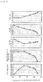
- Fig. 5 shows changes in operation values obtained from the temperature of each part when the opening degree of the expansion valve 3 changes.
- the horizontal axis represents the opening degree (%) of the expansion valve 3
- the vertical axis represents the suction superheat degree, discharge temperature, temperature difference ⁇ T2 between the outlet temperature of the water heat exchanger and water inlet temperature, heating ability ratio, COP ratio.
- the heating ability ratio and COP ratio show a ratio when a maximum value against the expansion valve opening degree is set as 100%, respectively.
- changes in the suction superheat degree can be regarded as almost a constant value, so that it is understood that changes in the heating ability ratio and the COP ratio cannot be judged by the suction superheat degree.
- Fig. 6 shows changes in other operation values obtained from temperatures of each part when the opening degree of the expansion valve 3 is changed.
- the horizontal axis represents the opening degree (%) of the expansion valve 3.
- the vertical axis represents an outlet/inlet temperature difference ⁇ Thx of the internal heat exchanger, a temperature difference ⁇ T between a discharge temperature and an outlet temperature of the water heat exchanger, a total temperature difference ⁇ t of the above ⁇ T1 and ⁇ T2, heating ability, and a COP ratio, respectively.
- a total temperature difference ⁇ t of the temperature difference ⁇ T1 between the water heat exchanger inlet temperature and water outlet temperature and the temperature difference ⁇ T2 between the water heat exchanger outlet temperature and water inlet temperature becomes a minimum.
- the control based on such an index has a physical meaning and being reasonable.
- high-precision temperature detection is required because change in temperature is small in the vicinity where the COP becomes a maximum compared with the temperature difference ⁇ T.
- a temperature difference ⁇ Tp at a pinch point is almost the same as that of ⁇ T2 between the water heat exchanger outlet temperature and water inlet temperature.
- Fig. 7 is a flowchart showing a control operation of the refrigeration cycle apparatus.
- the suction superheat degree (SHs) control of the compressor 1 precedes the temperature difference ⁇ T control for securing the heating ability.
- the expansion valve opening degree is increased until the suction superheat degree (SHs) converges.
- the temperature difference ⁇ T is made to converge at the target value.
- the temperature difference ⁇ T is made to converge at the target value.
- the expansion opening degree is increased and ⁇ T is made to converge.
- ⁇ Thx When using ⁇ Thx, internal heat exchanger outlet temperature detection means 52 is attached (refer to Fig. 1 ) between a high-pressure side outlet of the internal heat exchanger 5 and an inlet of the expansion valve 3, the temperature difference ⁇ Thx is obtained from a detection temperatures by the second temperature detection means 31 and the internal heat exchanger outlet temperature detection means 52.
- the expansion valve opening degree is made to be controlled so that the COP becomes maximum based on a temperature difference ⁇ Thx between the discharge temperature and the water heat exchanger outlet temperature, a high efficiency refrigeration cycle apparatus can be obtained.
- a refrigerant saturation temperature (ET) is obtained based on an output of the fifth temperature detection means 32 or pressure detection means, the suction superheat degree (SHs) is obtained by the detection temperature (Ts) of the sixth temperature detection means and the refrigerant saturation temperature (ET), and the expansion valve opening degree is controlled so that the suction superheat degree (SHs) becomes a target value, so that the superheat degree of the suction part of the compressor 1 is secured , liquid return to the compressor 1 can be prevented, and reliability can be secured.
- Ts detection temperature
- ET refrigerant saturation temperature
- the fifth temperature detection means 32 is provided between the expansion valve 3 and the evaporator 4, it can be disposed at any position between the inlet of the evaporator 4 and a low-pressure side inlet of the internal heat exchanger 5.
- the control of the superheat degree precedes the control of the above temperature differences. From this point, the reliability of the compressor 1 is secured.
- the radiator is composed of the water heat exchanger, so that a high efficiency hot water supply apparatus can be obtained.
- said radiator may be a heat exchanger that exchanges heat with water.
- carbon dioxide may be used as a refrigerant.
Landscapes
- Engineering & Computer Science (AREA)
- Chemical & Material Sciences (AREA)
- Chemical Kinetics & Catalysis (AREA)
- Physics & Mathematics (AREA)
- Mechanical Engineering (AREA)
- Thermal Sciences (AREA)
- General Engineering & Computer Science (AREA)
- Heat-Pump Type And Storage Water Heaters (AREA)
- Compression-Type Refrigeration Machines With Reversible Cycles (AREA)
- Air Conditioning Control Device (AREA)
Claims (7)
- Appareil à cycle de réfrigération qui comprend :au moins un compresseur (1), un radiateur (2), un moyen de décompression (3) capable de modifier un degré d'ouverture, un absorbeur de chaleur (4), un échangeur thermique interne (5) qui effectue un échange thermique entre un réfrigérant à la sortie du radiateur (2) et le réfrigérant à la sortie de l'absorbeur de chaleur (4), dans lequelun second moyen de détection de température (31) destiné à détecter une température de réfrigérant entre une sortie du radiateur (2) et une entrée côté haute pression de l'échangeur thermique interne (5), et un moyen de détection de température de sortie d'échangeur thermique interne (52) destiné à détecter la température de réfrigérant entre une sortie côté haute pression de l'échangeur thermique interne (5) et une entrée du moyen de compression (3) sont prévus,caractérisé en ce qu'un degré d'ouverture du moyen de décompression (3) est contrôlé de sorte qu'une différence de température (ΔThx) entre une température détectée par le second moyen de détection de température (31) et la température détectée par le moyen de détection de température de sortie d'échangeur thermique interne (52) devienne une valeur cible.
- Appareil à cycle de réfrigération selon la revendication 1, dans lequel un sixième moyen de détection de température (33) destiné à détecter la température de réfrigérant entre une sortie côté basse pression de l'échangeur thermique interne (5) et une entrée du compresseur (1) est prévu,
un degré de surchauffe d'une partie d'aspiration du compresseur est calculé à partir d'une température de saturation de réfrigérant à un point de détection du sixième moyen de détection de température (33) et d'une température détectée par le sixième moyen de détection de température (33), et
le degré d'ouverture du moyen de décompression (3) est contrôlé de sorte que le degré de surchauffe devienne la valeur cible. - Appareil à cycle de réfrigération selon la revendication 2, dans lequel un second moyen de détection de pression (51) est prévu entre la sortie côté basse pression de l'échangeur thermique interne (5) et l'entrée du compresseur (1), et
la température de saturation du réfrigérant est calculée sur la base d'une valeur de détection du second moyen de détection de pression (51). - Appareil à cycle de réfrigération selon la revendication 2, dans lequel un cinquième moyen de détection de température (32) est prévu entre l'entrée de l'absorbeur de chaleur (4) et l'entrée côté basse pression de l'échangeur thermique interne (5), et
la température de saturation du réfrigérant est calculée sur la base de la température de détection du cinquième moyen de détection de la température (32). - Appareil à cycle de réfrigération selon l'une quelconque des revendications 2 à 4, dans lequel
une priorité est donnée au contrôle du degré de surchauffe par rapport à la différence de température. - Appareil à cycle de réfrigération selon l'une quelconque des revendications 1 à 5, dans lequel
le radiateur (2) est un échangeur thermique qui échange la chaleur avec l'eau. - Appareil à cycle de réfrigération selon l'une quelconque des revendications 1 à 6, dans lequel
du dioxyde de carbone est utilisé comme réfrigérant.
Applications Claiming Priority (2)
| Application Number | Priority Date | Filing Date | Title |
|---|---|---|---|
| JP2007310097A JP4948374B2 (ja) | 2007-11-30 | 2007-11-30 | 冷凍サイクル装置 |
| EP08855672.5A EP2196745B1 (fr) | 2007-11-30 | 2008-11-20 | Dispositif de cycle de réfrigération |
Related Parent Applications (3)
| Application Number | Title | Priority Date | Filing Date |
|---|---|---|---|
| EP08855672.5 Division | 2008-11-20 | ||
| EP08855672.5A Division-Into EP2196745B1 (fr) | 2007-11-30 | 2008-11-20 | Dispositif de cycle de réfrigération |
| EP08855672.5A Division EP2196745B1 (fr) | 2007-11-30 | 2008-11-20 | Dispositif de cycle de réfrigération |
Publications (3)
| Publication Number | Publication Date |
|---|---|
| EP2647928A2 EP2647928A2 (fr) | 2013-10-09 |
| EP2647928A3 EP2647928A3 (fr) | 2015-08-05 |
| EP2647928B1 true EP2647928B1 (fr) | 2016-10-26 |
Family
ID=40678426
Family Applications (5)
| Application Number | Title | Priority Date | Filing Date |
|---|---|---|---|
| EP13166592.9A Not-in-force EP2647925B1 (fr) | 2007-11-30 | 2008-11-20 | Appareil de circuit de réfrigération |
| EP13166593.7A Not-in-force EP2647926B1 (fr) | 2007-11-30 | 2008-11-20 | Appareil de circuit de réfrigération |
| EP13166596.0A Not-in-force EP2647928B1 (fr) | 2007-11-30 | 2008-11-20 | Appareil de circuit de réfrigération |
| EP13166595.2A Active EP2647927B1 (fr) | 2007-11-30 | 2008-11-20 | Appareil de circuit de réfrigération |
| EP08855672.5A Not-in-force EP2196745B1 (fr) | 2007-11-30 | 2008-11-20 | Dispositif de cycle de réfrigération |
Family Applications Before (2)
| Application Number | Title | Priority Date | Filing Date |
|---|---|---|---|
| EP13166592.9A Not-in-force EP2647925B1 (fr) | 2007-11-30 | 2008-11-20 | Appareil de circuit de réfrigération |
| EP13166593.7A Not-in-force EP2647926B1 (fr) | 2007-11-30 | 2008-11-20 | Appareil de circuit de réfrigération |
Family Applications After (2)
| Application Number | Title | Priority Date | Filing Date |
|---|---|---|---|
| EP13166595.2A Active EP2647927B1 (fr) | 2007-11-30 | 2008-11-20 | Appareil de circuit de réfrigération |
| EP08855672.5A Not-in-force EP2196745B1 (fr) | 2007-11-30 | 2008-11-20 | Dispositif de cycle de réfrigération |
Country Status (7)
| Country | Link |
|---|---|
| US (1) | US20100205987A1 (fr) |
| EP (5) | EP2647925B1 (fr) |
| JP (1) | JP4948374B2 (fr) |
| CN (2) | CN101842645B (fr) |
| DK (5) | DK2196745T3 (fr) |
| ES (5) | ES2611980T3 (fr) |
| WO (1) | WO2009069524A1 (fr) |
Families Citing this family (43)
| Publication number | Priority date | Publication date | Assignee | Title |
|---|---|---|---|---|
| JP5330915B2 (ja) * | 2009-07-22 | 2013-10-30 | 株式会社前川製作所 | 2元冷凍サイクル装置及びその制御方法 |
| WO2011099074A1 (fr) * | 2010-02-12 | 2011-08-18 | 三菱電機株式会社 | Dispositif à cycle frigorifique |
| JP5558937B2 (ja) * | 2010-06-30 | 2014-07-23 | 株式会社コロナ | ヒートポンプ式給湯装置 |
| CN103154626B (zh) * | 2010-10-15 | 2015-11-25 | 东芝开利株式会社 | 热源装置 |
| US9429347B2 (en) * | 2011-08-04 | 2016-08-30 | Mitsubishi Electric Corporation | Refrigeration apparatus |
| KR20130041640A (ko) | 2011-10-17 | 2013-04-25 | 엘지전자 주식회사 | 공기조화기 및 그 운전 방법 |
| ES2632004T3 (es) * | 2011-10-25 | 2017-09-07 | Lg Electronics Inc. | Aire acondicionado y procedimiento de operación del mismo |
| CN103958986B (zh) * | 2011-11-29 | 2016-08-31 | 三菱电机株式会社 | 冷冻空调装置 |
| JP5875396B2 (ja) * | 2012-02-10 | 2016-03-02 | 三菱重工業株式会社 | ヒートポンプの制御装置、ヒートポンプ、及びヒートポンプの制御方法 |
| JP5861577B2 (ja) * | 2012-07-05 | 2016-02-16 | 株式会社デンソー | 給湯装置 |
| JP5831423B2 (ja) * | 2012-10-08 | 2015-12-09 | 株式会社デンソー | 冷凍サイクル装置 |
| JP6021945B2 (ja) * | 2012-12-26 | 2016-11-09 | 三菱電機株式会社 | 冷凍サイクル装置、及び冷凍サイクル装置の制御方法 |
| DE102013001455A1 (de) * | 2013-01-28 | 2014-08-14 | Hochschule für angewandte Wissenschaften München | Anordnung und Verfahren zur Wärmeversorgung eines Gebäudes |
| WO2014129361A1 (fr) * | 2013-02-19 | 2014-08-28 | 三菱電機株式会社 | Climatiseur |
| DE102013210175A1 (de) | 2013-05-31 | 2014-12-18 | Siemens Aktiengesellschaft | Wärmepumpe zur Verwendung von umweltverträglichen Kältemitteln |
| CN105940276A (zh) * | 2014-01-23 | 2016-09-14 | 三菱电机株式会社 | 热泵装置 |
| JP5874754B2 (ja) * | 2014-01-31 | 2016-03-02 | ダイキン工業株式会社 | 冷凍装置 |
| EP3128256A4 (fr) * | 2014-03-10 | 2017-12-27 | Mitsubishi Electric Corporation | Système de pompe à chaleur |
| US20170248354A1 (en) * | 2014-10-09 | 2017-08-31 | Carrier Corporation | Internal liquid suction heat exchanger |
| JP6328270B2 (ja) * | 2014-12-05 | 2018-05-23 | 三菱電機株式会社 | 空気調和装置 |
| JP6456139B2 (ja) * | 2014-12-26 | 2019-01-23 | 株式会社前川製作所 | 冷凍又は空調装置及びその制御方法 |
| EP3350523B1 (fr) * | 2015-09-18 | 2020-06-10 | Carrier Corporation | Système et procede de protection au gel pour une unité de refroidissement |
| JP2017088137A (ja) * | 2015-11-17 | 2017-05-25 | 株式会社ヴァレオジャパン | 車両用空調装置の冷凍サイクル及びこれを搭載した車両 |
| JP6745657B2 (ja) * | 2016-06-29 | 2020-08-26 | リンナイ株式会社 | 給湯システム |
| EP3594587B1 (fr) * | 2017-03-09 | 2021-04-21 | Mitsubishi Electric Corporation | Dispositif d'alimentation en eau chaude d'une pompe à chaleur |
| WO2020075238A1 (fr) * | 2018-10-10 | 2020-04-16 | 三菱電機株式会社 | Échangeur de chaleur à plaques et dispositif de pompe à chaleur |
| CN111854206B (zh) * | 2019-04-28 | 2022-01-25 | 青岛海尔智能技术研发有限公司 | 一种冷柜设备、制冷系统及其控制方法 |
| AT522875B1 (de) * | 2019-10-30 | 2021-03-15 | Lambda Waermepumpen Gmbh | Verfahren zur Regelung eines Expansionsventils |
| DE102020115274A1 (de) | 2020-06-09 | 2021-12-09 | Stiebel Eltron Gmbh & Co. Kg | Verfahren zum Betrieb einer Kompressionskälteanlage |
| WO2022044321A1 (fr) * | 2020-08-31 | 2022-03-03 | 三菱電機株式会社 | Système à cycle de réfrigération |
| JP7014988B1 (ja) * | 2020-12-02 | 2022-02-02 | ダイキン工業株式会社 | 冷凍装置 |
| WO2022162819A1 (fr) * | 2021-01-28 | 2022-08-04 | 日立ジョンソンコントロールズ空調株式会社 | Dispositif de climatisation |
| CN113432298B (zh) * | 2021-06-28 | 2022-03-22 | 珠海格力电器股份有限公司 | 压缩系统的控制方法、装置及空气能热泵热水器 |
| JP2023028241A (ja) * | 2021-08-19 | 2023-03-03 | パナソニックIpマネジメント株式会社 | 空気調和機 |
| DE102021127213A1 (de) | 2021-10-20 | 2023-04-20 | Lauda Dr. R. Wobser Gmbh & Co. Kg | Kälteanlage und Verfahren zum Betreiben einer Kälteanlage |
| CN114234450B (zh) * | 2021-12-24 | 2023-09-08 | 山东雅士股份有限公司 | 一种变频co2热水机机组的控制方法 |
| US20230417429A1 (en) * | 2022-06-24 | 2023-12-28 | Nutech Ventures | Virtual Superheat Measurement Sensor for Refrigeration Cycle |
| DE102022118670A1 (de) * | 2022-07-26 | 2024-02-01 | Lauda Dr. R. Wobser Gmbh & Co. Kg | Prozesskühlaggregat und Verfahren zur Regelung eines Prozesskühlaggregrats |
| CN116294333B (zh) * | 2023-04-04 | 2025-07-22 | 广东美的制冷设备有限公司 | 热泵系统的控制方法、控制装置、热泵系统及存储介质 |
| WO2024248986A2 (fr) * | 2023-05-29 | 2024-12-05 | A. O. Smith Corporation | Système de chauffage d'eau |
| JP2025005169A (ja) * | 2023-06-27 | 2025-01-16 | 株式会社ディスコ | 冷却機構 |
| JP2025035577A (ja) * | 2023-09-04 | 2025-03-14 | パナソニックIpマネジメント株式会社 | 熱媒体循環装置 |
| EP4610580A1 (fr) * | 2024-02-28 | 2025-09-03 | Frede Schmidt | Procédé de commande de la pression latérale élevée d'un système de pompe à chaleur à compression de vapeur transcritique, et pompe à chaleur utilisant le procédé |
Family Cites Families (32)
| Publication number | Priority date | Publication date | Assignee | Title |
|---|---|---|---|---|
| JPH05106922A (ja) * | 1991-10-18 | 1993-04-27 | Hitachi Ltd | 冷凍装置の制御方式 |
| US5457965A (en) * | 1994-04-11 | 1995-10-17 | Ford Motor Company | Low refrigerant charge detection system |
| DE69533120D1 (de) * | 1994-05-30 | 2004-07-15 | Mitsubishi Electric Corp | Kühlmittelumlaufsystem |
| JPH0966736A (ja) * | 1995-06-23 | 1997-03-11 | Denso Corp | 車両用空調装置 |
| US5704219A (en) * | 1995-08-01 | 1998-01-06 | Nippondenso Co., Ltd. | Air conditioning apparatus |
| JPH11108485A (ja) * | 1997-09-30 | 1999-04-23 | Matsushita Electric Ind Co Ltd | 空気調和機及び冷媒加熱器出口温度の制御方法 |
| JP3227651B2 (ja) * | 1998-11-18 | 2001-11-12 | 株式会社デンソー | 給湯器 |
| JP3601369B2 (ja) * | 1999-09-03 | 2004-12-15 | ダイキン工業株式会社 | 給湯装置 |
| JP2001235239A (ja) * | 2000-02-23 | 2001-08-31 | Seiko Seiki Co Ltd | 超臨界蒸気圧縮サイクル装置 |
| EP1148307B1 (fr) * | 2000-04-19 | 2004-03-17 | Denso Corporation | Chauffe-eau avec pompe à chaleur |
| JP3737381B2 (ja) * | 2000-06-05 | 2006-01-18 | 株式会社デンソー | 給湯装置 |
| JP4538919B2 (ja) * | 2000-08-08 | 2010-09-08 | 三菱電機株式会社 | 室内マルチ空気調和機 |
| JP2003176957A (ja) * | 2001-10-03 | 2003-06-27 | Denso Corp | 冷凍サイクル装置 |
| US7076964B2 (en) * | 2001-10-03 | 2006-07-18 | Denso Corporation | Super-critical refrigerant cycle system and water heater using the same |
| JP3737414B2 (ja) * | 2001-11-05 | 2006-01-18 | 株式会社デンソー | 給湯装置 |
| TWI263025B (en) * | 2002-01-24 | 2006-10-01 | Daikin Ind Ltd | Freezing device |
| JP2004061061A (ja) * | 2002-07-31 | 2004-02-26 | Matsushita Electric Ind Co Ltd | 冷凍サイクル装置およびその運転方法 |
| US7000413B2 (en) * | 2003-06-26 | 2006-02-21 | Carrier Corporation | Control of refrigeration system to optimize coefficient of performance |
| JP3915770B2 (ja) * | 2003-10-31 | 2007-05-16 | 松下電器産業株式会社 | ヒートポンプ給湯機 |
| JP2005156030A (ja) * | 2003-11-26 | 2005-06-16 | Hitachi Home & Life Solutions Inc | ヒートポンプ装置 |
| JP4269323B2 (ja) * | 2004-03-29 | 2009-05-27 | 三菱電機株式会社 | ヒートポンプ給湯機 |
| CN100494829C (zh) * | 2004-05-20 | 2009-06-03 | 上海交通大学 | 蒸发器出口制冷剂为大干度二相状态的高效制冷系统 |
| EP1777471A1 (fr) * | 2004-07-12 | 2007-04-25 | Denso Corporation | Dispositif d'alimentation en eau chaude de type pompe à chaleur |
| JP2006077998A (ja) * | 2004-09-07 | 2006-03-23 | Matsushita Electric Ind Co Ltd | 冷凍サイクル装置および制御方法 |
| JP4459776B2 (ja) * | 2004-10-18 | 2010-04-28 | 三菱電機株式会社 | ヒートポンプ装置及びヒートポンプ装置の室外機 |
| JP4670329B2 (ja) * | 2004-11-29 | 2011-04-13 | 三菱電機株式会社 | 冷凍空調装置、冷凍空調装置の運転制御方法、冷凍空調装置の冷媒量制御方法 |
| US8096141B2 (en) * | 2005-01-25 | 2012-01-17 | Trane International Inc. | Superheat control by pressure ratio |
| CN1862151A (zh) * | 2005-05-12 | 2006-11-15 | 乐金电子(天津)电器有限公司 | 回热式制冷循环系统空调器 |
| JP2007093100A (ja) * | 2005-09-28 | 2007-04-12 | Mitsubishi Electric Corp | ヒートポンプ給湯機の制御方法及びヒートポンプ給湯機 |
| DE602007001038D1 (de) * | 2006-01-31 | 2009-06-18 | Sanyo Electric Co | Klimaanlage |
| JP4613916B2 (ja) * | 2006-03-17 | 2011-01-19 | 三菱電機株式会社 | ヒートポンプ給湯機 |
| JP4569508B2 (ja) * | 2006-03-31 | 2010-10-27 | 株式会社デンソー | 超臨界サイクル及び冷凍サイクルに用いられる膨張弁 |
-
2007
- 2007-11-30 JP JP2007310097A patent/JP4948374B2/ja active Active
-
2008
- 2008-11-20 US US12/738,924 patent/US20100205987A1/en not_active Abandoned
- 2008-11-20 WO PCT/JP2008/071069 patent/WO2009069524A1/fr not_active Ceased
- 2008-11-20 ES ES13166592.9T patent/ES2611980T3/es active Active
- 2008-11-20 ES ES08855672.5T patent/ES2650233T3/es active Active
- 2008-11-20 EP EP13166592.9A patent/EP2647925B1/fr not_active Not-in-force
- 2008-11-20 CN CN2008801141141A patent/CN101842645B/zh not_active Expired - Fee Related
- 2008-11-20 DK DK08855672.5T patent/DK2196745T3/en active
- 2008-11-20 CN CN201110289736.1A patent/CN102425872B/zh not_active Expired - Fee Related
- 2008-11-20 DK DK13166593.7T patent/DK2647926T3/en active
- 2008-11-20 EP EP13166593.7A patent/EP2647926B1/fr not_active Not-in-force
- 2008-11-20 EP EP13166596.0A patent/EP2647928B1/fr not_active Not-in-force
- 2008-11-20 DK DK13166595.2T patent/DK2647927T3/da active
- 2008-11-20 ES ES13166595T patent/ES2823758T3/es active Active
- 2008-11-20 DK DK13166596.0T patent/DK2647928T3/en active
- 2008-11-20 EP EP13166595.2A patent/EP2647927B1/fr active Active
- 2008-11-20 ES ES13166593T patent/ES2700938T3/es active Active
- 2008-11-20 DK DK13166592.9T patent/DK2647925T3/en active
- 2008-11-20 ES ES13166596.0T patent/ES2605462T3/es active Active
- 2008-11-20 EP EP08855672.5A patent/EP2196745B1/fr not_active Not-in-force
Also Published As
| Publication number | Publication date |
|---|---|
| WO2009069524A1 (fr) | 2009-06-04 |
| CN101842645B (zh) | 2012-11-28 |
| CN101842645A (zh) | 2010-09-22 |
| DK2196745T3 (en) | 2017-12-11 |
| ES2823758T3 (es) | 2021-05-10 |
| EP2647928A2 (fr) | 2013-10-09 |
| EP2647925A2 (fr) | 2013-10-09 |
| JP4948374B2 (ja) | 2012-06-06 |
| EP2196745A4 (fr) | 2013-02-13 |
| DK2647927T3 (da) | 2020-10-19 |
| EP2196745B1 (fr) | 2017-11-08 |
| EP2647927B1 (fr) | 2020-09-16 |
| EP2647927A2 (fr) | 2013-10-09 |
| EP2647925B1 (fr) | 2016-12-21 |
| CN102425872A (zh) | 2012-04-25 |
| EP2647926B1 (fr) | 2018-10-24 |
| EP2647925A3 (fr) | 2015-08-05 |
| JP2009133547A (ja) | 2009-06-18 |
| DK2647925T3 (en) | 2017-02-06 |
| EP2647928A3 (fr) | 2015-08-05 |
| ES2650233T3 (es) | 2018-01-17 |
| US20100205987A1 (en) | 2010-08-19 |
| DK2647928T3 (en) | 2016-12-12 |
| ES2605462T3 (es) | 2017-03-14 |
| EP2647926A3 (fr) | 2015-07-29 |
| EP2196745A1 (fr) | 2010-06-16 |
| ES2611980T3 (es) | 2017-05-11 |
| CN102425872B (zh) | 2014-06-25 |
| DK2647926T3 (en) | 2019-01-07 |
| ES2700938T3 (es) | 2019-02-20 |
| EP2647927A3 (fr) | 2015-07-29 |
| EP2647926A2 (fr) | 2013-10-09 |
Similar Documents
| Publication | Publication Date | Title |
|---|---|---|
| EP2647928B1 (fr) | Appareil de circuit de réfrigération | |
| US8353173B2 (en) | Refrigerating cycle apparatus and operation control method therefor | |
| CN105157266B (zh) | 制冷剂蒸气压缩系统的运行 | |
| EP2631562B1 (fr) | Dispositif de chauffage de l'air du type pompe à chaleur | |
| JP5196452B2 (ja) | 充填量管理を備えた遷臨界冷媒蒸気圧縮システム | |
| EP2107322A2 (fr) | Appareil extérieur d'alimentation en eau chaude de type pompe à chaleur | |
| US7210303B2 (en) | Transcritical heat pump water heating system using auxiliary electric heater | |
| KR101445992B1 (ko) | 열매체 유량 추정 장치, 열원기 및 열매체 유량 추정 방법 | |
| JP4337880B2 (ja) | ヒートポンプ式給湯器 | |
| JP2010526985A (ja) | フラッシュタンクエコノマイザを備えた冷媒蒸気圧縮システム | |
| JP2011521194A (ja) | 冷媒蒸気圧縮システムにおける充填管理 | |
| US20100023166A1 (en) | Free-cooling limitation control for air conditioning systems | |
| EP2589901A2 (fr) | Appareil de cycle de réfrigération et générateur d'eau chaude | |
| EP2594867A2 (fr) | Appareil de cycle de réfrigération et appareil de production d'eau chaude | |
| EP2538159A2 (fr) | Appareil à cycle de réfrigération et appareil de chauffage hydronique comportant l'appareil à cycle de réfrigération | |
| JP2019060581A (ja) | 冷凍サイクル装置 | |
| CA2779757A1 (fr) | Dispositif de regulation de la temperature d'un compresseur d'aspiration pour des compresseurs r-744 transcritiques et sous-critiques | |
| JP2007046860A (ja) | エジェクタ式冷凍サイクル | |
| HK1172944A (en) | Refrigerant vapor compression system operation |
Legal Events
| Date | Code | Title | Description |
|---|---|---|---|
| PUAI | Public reference made under article 153(3) epc to a published international application that has entered the european phase |
Free format text: ORIGINAL CODE: 0009012 |
|
| 17P | Request for examination filed |
Effective date: 20130506 |
|
| AC | Divisional application: reference to earlier application |
Ref document number: 2196745 Country of ref document: EP Kind code of ref document: P |
|
| AK | Designated contracting states |
Kind code of ref document: A2 Designated state(s): AT BE BG CH CY CZ DE DK EE ES FI FR GB GR HR HU IE IS IT LI LT LU LV MC MT NL NO PL PT RO SE SI SK TR |
|
| PUAL | Search report despatched |
Free format text: ORIGINAL CODE: 0009013 |
|
| AK | Designated contracting states |
Kind code of ref document: A3 Designated state(s): AT BE BG CH CY CZ DE DK EE ES FI FR GB GR HR HU IE IS IT LI LT LU LV MC MT NL NO PL PT RO SE SI SK TR |
|
| RIC1 | Information provided on ipc code assigned before grant |
Ipc: F25B 1/00 20060101AFI20150702BHEP |
|
| RIC1 | Information provided on ipc code assigned before grant |
Ipc: F25B 9/00 20060101AFI20160107BHEP |
|
| GRAP | Despatch of communication of intention to grant a patent |
Free format text: ORIGINAL CODE: EPIDOSNIGR1 |
|
| INTG | Intention to grant announced |
Effective date: 20160509 |
|
| GRAS | Grant fee paid |
Free format text: ORIGINAL CODE: EPIDOSNIGR3 |
|
| GRAA | (expected) grant |
Free format text: ORIGINAL CODE: 0009210 |
|
| AC | Divisional application: reference to earlier application |
Ref document number: 2196745 Country of ref document: EP Kind code of ref document: P |
|
| AK | Designated contracting states |
Kind code of ref document: B1 Designated state(s): AT BE BG CH CY CZ DE DK EE ES FI FR GB GR HR HU IE IS IT LI LT LU LV MC MT NL NO PL PT RO SE SI SK TR |
|
| REG | Reference to a national code |
Ref country code: GB Ref legal event code: FG4D |
|
| REG | Reference to a national code |
Ref country code: CH Ref legal event code: EP |
|
| REG | Reference to a national code |
Ref country code: AT Ref legal event code: REF Ref document number: 840310 Country of ref document: AT Kind code of ref document: T Effective date: 20161115 |
|
| REG | Reference to a national code |
Ref country code: IE Ref legal event code: FG4D |
|
| REG | Reference to a national code |
Ref country code: FR Ref legal event code: PLFP Year of fee payment: 9 |
|
| REG | Reference to a national code |
Ref country code: DE Ref legal event code: R096 Ref document number: 602008047120 Country of ref document: DE |
|
| REG | Reference to a national code |
Ref country code: DK Ref legal event code: T3 Effective date: 20161209 |
|
| REG | Reference to a national code |
Ref country code: SE Ref legal event code: TRGR |
|
| REG | Reference to a national code |
Ref country code: LT Ref legal event code: MG4D |
|
| PG25 | Lapsed in a contracting state [announced via postgrant information from national office to epo] |
Ref country code: BE Free format text: LAPSE BECAUSE OF NON-PAYMENT OF DUE FEES Effective date: 20161130 Ref country code: LV Free format text: LAPSE BECAUSE OF FAILURE TO SUBMIT A TRANSLATION OF THE DESCRIPTION OR TO PAY THE FEE WITHIN THE PRESCRIBED TIME-LIMIT Effective date: 20161026 |
|
| REG | Reference to a national code |
Ref country code: NL Ref legal event code: MP Effective date: 20161026 |
|
| REG | Reference to a national code |
Ref country code: ES Ref legal event code: FG2A Ref document number: 2605462 Country of ref document: ES Kind code of ref document: T3 Effective date: 20170314 |
|
| REG | Reference to a national code |
Ref country code: AT Ref legal event code: MK05 Ref document number: 840310 Country of ref document: AT Kind code of ref document: T Effective date: 20161026 |
|
| PG25 | Lapsed in a contracting state [announced via postgrant information from national office to epo] |
Ref country code: NO Free format text: LAPSE BECAUSE OF FAILURE TO SUBMIT A TRANSLATION OF THE DESCRIPTION OR TO PAY THE FEE WITHIN THE PRESCRIBED TIME-LIMIT Effective date: 20170126 Ref country code: GR Free format text: LAPSE BECAUSE OF FAILURE TO SUBMIT A TRANSLATION OF THE DESCRIPTION OR TO PAY THE FEE WITHIN THE PRESCRIBED TIME-LIMIT Effective date: 20170127 Ref country code: LT Free format text: LAPSE BECAUSE OF FAILURE TO SUBMIT A TRANSLATION OF THE DESCRIPTION OR TO PAY THE FEE WITHIN THE PRESCRIBED TIME-LIMIT Effective date: 20161026 |
|
| PG25 | Lapsed in a contracting state [announced via postgrant information from national office to epo] |
Ref country code: NL Free format text: LAPSE BECAUSE OF FAILURE TO SUBMIT A TRANSLATION OF THE DESCRIPTION OR TO PAY THE FEE WITHIN THE PRESCRIBED TIME-LIMIT Effective date: 20161026 Ref country code: AT Free format text: LAPSE BECAUSE OF FAILURE TO SUBMIT A TRANSLATION OF THE DESCRIPTION OR TO PAY THE FEE WITHIN THE PRESCRIBED TIME-LIMIT Effective date: 20161026 Ref country code: PT Free format text: LAPSE BECAUSE OF FAILURE TO SUBMIT A TRANSLATION OF THE DESCRIPTION OR TO PAY THE FEE WITHIN THE PRESCRIBED TIME-LIMIT Effective date: 20170227 Ref country code: PL Free format text: LAPSE BECAUSE OF FAILURE TO SUBMIT A TRANSLATION OF THE DESCRIPTION OR TO PAY THE FEE WITHIN THE PRESCRIBED TIME-LIMIT Effective date: 20161026 Ref country code: FI Free format text: LAPSE BECAUSE OF FAILURE TO SUBMIT A TRANSLATION OF THE DESCRIPTION OR TO PAY THE FEE WITHIN THE PRESCRIBED TIME-LIMIT Effective date: 20161026 Ref country code: IS Free format text: LAPSE BECAUSE OF FAILURE TO SUBMIT A TRANSLATION OF THE DESCRIPTION OR TO PAY THE FEE WITHIN THE PRESCRIBED TIME-LIMIT Effective date: 20170226 Ref country code: BE Free format text: LAPSE BECAUSE OF FAILURE TO SUBMIT A TRANSLATION OF THE DESCRIPTION OR TO PAY THE FEE WITHIN THE PRESCRIBED TIME-LIMIT Effective date: 20161026 Ref country code: HR Free format text: LAPSE BECAUSE OF FAILURE TO SUBMIT A TRANSLATION OF THE DESCRIPTION OR TO PAY THE FEE WITHIN THE PRESCRIBED TIME-LIMIT Effective date: 20161026 |
|
| REG | Reference to a national code |
Ref country code: CH Ref legal event code: PL |
|
| REG | Reference to a national code |
Ref country code: DE Ref legal event code: R097 Ref document number: 602008047120 Country of ref document: DE |
|
| PG25 | Lapsed in a contracting state [announced via postgrant information from national office to epo] |
Ref country code: SK Free format text: LAPSE BECAUSE OF FAILURE TO SUBMIT A TRANSLATION OF THE DESCRIPTION OR TO PAY THE FEE WITHIN THE PRESCRIBED TIME-LIMIT Effective date: 20161026 Ref country code: LI Free format text: LAPSE BECAUSE OF NON-PAYMENT OF DUE FEES Effective date: 20161130 Ref country code: CH Free format text: LAPSE BECAUSE OF NON-PAYMENT OF DUE FEES Effective date: 20161130 Ref country code: EE Free format text: LAPSE BECAUSE OF FAILURE TO SUBMIT A TRANSLATION OF THE DESCRIPTION OR TO PAY THE FEE WITHIN THE PRESCRIBED TIME-LIMIT Effective date: 20161026 Ref country code: RO Free format text: LAPSE BECAUSE OF FAILURE TO SUBMIT A TRANSLATION OF THE DESCRIPTION OR TO PAY THE FEE WITHIN THE PRESCRIBED TIME-LIMIT Effective date: 20161026 Ref country code: MC Free format text: LAPSE BECAUSE OF FAILURE TO SUBMIT A TRANSLATION OF THE DESCRIPTION OR TO PAY THE FEE WITHIN THE PRESCRIBED TIME-LIMIT Effective date: 20161026 Ref country code: CZ Free format text: LAPSE BECAUSE OF FAILURE TO SUBMIT A TRANSLATION OF THE DESCRIPTION OR TO PAY THE FEE WITHIN THE PRESCRIBED TIME-LIMIT Effective date: 20161026 |
|
| REG | Reference to a national code |
Ref country code: IE Ref legal event code: MM4A |
|
| PG25 | Lapsed in a contracting state [announced via postgrant information from national office to epo] |
Ref country code: IT Free format text: LAPSE BECAUSE OF FAILURE TO SUBMIT A TRANSLATION OF THE DESCRIPTION OR TO PAY THE FEE WITHIN THE PRESCRIBED TIME-LIMIT Effective date: 20161026 Ref country code: BG Free format text: LAPSE BECAUSE OF FAILURE TO SUBMIT A TRANSLATION OF THE DESCRIPTION OR TO PAY THE FEE WITHIN THE PRESCRIBED TIME-LIMIT Effective date: 20170126 |
|
| PLBE | No opposition filed within time limit |
Free format text: ORIGINAL CODE: 0009261 |
|
| STAA | Information on the status of an ep patent application or granted ep patent |
Free format text: STATUS: NO OPPOSITION FILED WITHIN TIME LIMIT |
|
| PG25 | Lapsed in a contracting state [announced via postgrant information from national office to epo] |
Ref country code: LU Free format text: LAPSE BECAUSE OF NON-PAYMENT OF DUE FEES Effective date: 20161130 |
|
| 26N | No opposition filed |
Effective date: 20170727 |
|
| REG | Reference to a national code |
Ref country code: FR Ref legal event code: PLFP Year of fee payment: 10 |
|
| PG25 | Lapsed in a contracting state [announced via postgrant information from national office to epo] |
Ref country code: SI Free format text: LAPSE BECAUSE OF FAILURE TO SUBMIT A TRANSLATION OF THE DESCRIPTION OR TO PAY THE FEE WITHIN THE PRESCRIBED TIME-LIMIT Effective date: 20161026 Ref country code: IE Free format text: LAPSE BECAUSE OF NON-PAYMENT OF DUE FEES Effective date: 20161120 |
|
| PG25 | Lapsed in a contracting state [announced via postgrant information from national office to epo] |
Ref country code: HU Free format text: LAPSE BECAUSE OF FAILURE TO SUBMIT A TRANSLATION OF THE DESCRIPTION OR TO PAY THE FEE WITHIN THE PRESCRIBED TIME-LIMIT; INVALID AB INITIO Effective date: 20081120 Ref country code: CY Free format text: LAPSE BECAUSE OF FAILURE TO SUBMIT A TRANSLATION OF THE DESCRIPTION OR TO PAY THE FEE WITHIN THE PRESCRIBED TIME-LIMIT Effective date: 20161026 |
|
| PG25 | Lapsed in a contracting state [announced via postgrant information from national office to epo] |
Ref country code: MT Free format text: LAPSE BECAUSE OF NON-PAYMENT OF DUE FEES Effective date: 20161120 |
|
| REG | Reference to a national code |
Ref country code: FR Ref legal event code: PLFP Year of fee payment: 11 |
|
| PG25 | Lapsed in a contracting state [announced via postgrant information from national office to epo] |
Ref country code: TR Free format text: LAPSE BECAUSE OF FAILURE TO SUBMIT A TRANSLATION OF THE DESCRIPTION OR TO PAY THE FEE WITHIN THE PRESCRIBED TIME-LIMIT Effective date: 20161026 |
|
| REG | Reference to a national code |
Ref country code: DE Ref legal event code: R084 Ref document number: 602008047120 Country of ref document: DE |
|
| REG | Reference to a national code |
Ref country code: GB Ref legal event code: 746 Effective date: 20190122 |
|
| REG | Reference to a national code |
Ref country code: ES Ref legal event code: GC2A Effective date: 20190416 |
|
| P01 | Opt-out of the competence of the unified patent court (upc) registered |
Effective date: 20230512 |
|
| PGFP | Annual fee paid to national office [announced via postgrant information from national office to epo] |
Ref country code: GB Payment date: 20230928 Year of fee payment: 16 |
|
| PGFP | Annual fee paid to national office [announced via postgrant information from national office to epo] |
Ref country code: FR Payment date: 20230929 Year of fee payment: 16 |
|
| PGFP | Annual fee paid to national office [announced via postgrant information from national office to epo] |
Ref country code: ES Payment date: 20231201 Year of fee payment: 16 |
|
| PGFP | Annual fee paid to national office [announced via postgrant information from national office to epo] |
Ref country code: SE Payment date: 20231002 Year of fee payment: 16 Ref country code: DE Payment date: 20230929 Year of fee payment: 16 |
|
| PGFP | Annual fee paid to national office [announced via postgrant information from national office to epo] |
Ref country code: DK Payment date: 20240109 Year of fee payment: 16 |
|
| REG | Reference to a national code |
Ref country code: DE Ref legal event code: R119 Ref document number: 602008047120 Country of ref document: DE |
|
| REG | Reference to a national code |
Ref country code: DK Ref legal event code: EBP Effective date: 20241130 |
|
| REG | Reference to a national code |
Ref country code: SE Ref legal event code: EUG |
|
| GBPC | Gb: european patent ceased through non-payment of renewal fee |
Effective date: 20241120 |
|
| PG25 | Lapsed in a contracting state [announced via postgrant information from national office to epo] |
Ref country code: DE Free format text: LAPSE BECAUSE OF NON-PAYMENT OF DUE FEES Effective date: 20250603 Ref country code: DK Free format text: LAPSE BECAUSE OF NON-PAYMENT OF DUE FEES Effective date: 20241130 |
|
| PG25 | Lapsed in a contracting state [announced via postgrant information from national office to epo] |
Ref country code: SE Free format text: LAPSE BECAUSE OF NON-PAYMENT OF DUE FEES Effective date: 20241121 |
|
| PG25 | Lapsed in a contracting state [announced via postgrant information from national office to epo] |
Ref country code: GB Free format text: LAPSE BECAUSE OF NON-PAYMENT OF DUE FEES Effective date: 20241120 |
|
| PG25 | Lapsed in a contracting state [announced via postgrant information from national office to epo] |
Ref country code: FR Free format text: LAPSE BECAUSE OF NON-PAYMENT OF DUE FEES Effective date: 20241130 |
|
| REG | Reference to a national code |
Ref country code: ES Ref legal event code: FD2A Effective date: 20260105 |
|
| PG25 | Lapsed in a contracting state [announced via postgrant information from national office to epo] |
Ref country code: ES Free format text: LAPSE BECAUSE OF NON-PAYMENT OF DUE FEES Effective date: 20241121 |