EP2647983A2 - Appareil spectroscopique - Google Patents
Appareil spectroscopique Download PDFInfo
- Publication number
- EP2647983A2 EP2647983A2 EP13001723.9A EP13001723A EP2647983A2 EP 2647983 A2 EP2647983 A2 EP 2647983A2 EP 13001723 A EP13001723 A EP 13001723A EP 2647983 A2 EP2647983 A2 EP 2647983A2
- Authority
- EP
- European Patent Office
- Prior art keywords
- diffraction grating
- line spacing
- grating
- vls
- spectroscopic apparatus
- Prior art date
- Legal status (The legal status is an assumption and is not a legal conclusion. Google has not performed a legal analysis and makes no representation as to the accuracy of the status listed.)
- Granted
Links
Images





Classifications
-
- G—PHYSICS
- G21—NUCLEAR PHYSICS; NUCLEAR ENGINEERING
- G21K—HANDLING OF PARTICLES OR IONISING RADIATION NOT OTHERWISE PROVIDED FOR; IRRADIATION DEVICES; GAMMA RAY OR X-RAY MICROSCOPES
- G21K1/00—Arrangements for handling particles or ionising radiation, e.g. focusing or moderating
- G21K1/06—Arrangements for handling particles or ionising radiation, e.g. focusing or moderating using diffraction, refraction or reflection, e.g. monochromators
-
- G—PHYSICS
- G01—MEASURING; TESTING
- G01N—INVESTIGATING OR ANALYSING MATERIALS BY DETERMINING THEIR CHEMICAL OR PHYSICAL PROPERTIES
- G01N23/00—Investigating or analysing materials by the use of wave or particle radiation, e.g. X-rays or neutrons, not covered by groups G01N3/00 – G01N17/00, G01N21/00 or G01N22/00
- G01N23/20—Investigating or analysing materials by the use of wave or particle radiation, e.g. X-rays or neutrons, not covered by groups G01N3/00 – G01N17/00, G01N21/00 or G01N22/00 by using diffraction of the radiation by the materials, e.g. for investigating crystal structure; by using scattering of the radiation by the materials, e.g. for investigating non-crystalline materials; by using reflection of the radiation by the materials
-
- G—PHYSICS
- G21—NUCLEAR PHYSICS; NUCLEAR ENGINEERING
- G21K—HANDLING OF PARTICLES OR IONISING RADIATION NOT OTHERWISE PROVIDED FOR; IRRADIATION DEVICES; GAMMA RAY OR X-RAY MICROSCOPES
- G21K1/00—Arrangements for handling particles or ionising radiation, e.g. focusing or moderating
- G21K1/06—Arrangements for handling particles or ionising radiation, e.g. focusing or moderating using diffraction, refraction or reflection, e.g. monochromators
- G21K1/067—Arrangements for handling particles or ionising radiation, e.g. focusing or moderating using diffraction, refraction or reflection, e.g. monochromators using surface reflection, e.g. grazing incidence mirrors, gratings
-
- G—PHYSICS
- G21—NUCLEAR PHYSICS; NUCLEAR ENGINEERING
- G21K—HANDLING OF PARTICLES OR IONISING RADIATION NOT OTHERWISE PROVIDED FOR; IRRADIATION DEVICES; GAMMA RAY OR X-RAY MICROSCOPES
- G21K1/00—Arrangements for handling particles or ionising radiation, e.g. focusing or moderating
- G21K1/06—Arrangements for handling particles or ionising radiation, e.g. focusing or moderating using diffraction, refraction or reflection, e.g. monochromators
- G21K1/062—Devices having a multilayer structure
Definitions
- the present invention relates to a spectroscopic apparatus which uses a varied line spacing diffraction grating.
- the spectroscopic apparatus which, from a non-monochromatic incident light, outputs monochromatic light having a desired wavelength has found widespread use in various physical experiments and measurements.
- a spectroscopic apparatus using a diffraction grating(for example, a laminar-type diffraction grating having rectangular grooves) is known.
- a monochromatic ray having a desired wavelength can be obtained.
- image formation can be simultaneously performed in addition to spectral dispersion.
- Patent Literature 1 With such a diffraction grating for the soft x-ray region, the wavelength range (energy range) which can be obtained using one diffraction grating is limited, and in the range beyond this limit, the diffraction efficiency is greatly reduced or the resolution is greatly lowered. Therefore, a structure for the purpose of widening this range has been proposed.
- Patent Literature 1 there is disclosed a varied line spacing (VLS)diffraction grating which has widened this range by providing the lattice plane with a distribution of line spacings rather than a uniform line spacing.
- Patent Literature 2 discloses a configuration in which the diffraction plane of the diffraction grating is divided into a plurality of regions, and in the respective regions, the range of wavelengths to be accommodated is optimized.
- the energy range in which a practicable diffraction efficiency and resolution can be maintained is 60 to 250 eV (20 to 5 nm wavelength) or so, assuming that, for example, the central value of the grating constant is set at 1/1200 mm, and the incident angle (the angle between the grating normal and the incident ray) is at 87°.
- the image plane for a diffracted light by a VLS concave grating can be made flat, in the case where a two-dimensional detector, such as a charge coupled device (CCD), is used as a detector, the light in the relevant energy region can be simultaneously detected.
- a two-dimensional detector such as a charge coupled device (CCD)
- CCD charge coupled device
- the lattice constant is set at 1/2400 mm, and the angle of incidence at 88.7°
- the energy range of 250 to 1240 eV (5 to 1 nm wavelength) or so is obtained.
- the image plane can be made flat, the light in the relevant energy region can be simultaneously detected.
- Patent Literature 3 there is disclosed a technology which uses a plurality of VLS gratings by switching over among them. This technology employs translation or pivoting movement to switch over among the plurality of VLS gratings.
- the parameters such as the grating constant, the groove pattern (groove function), the groove shape, and the curvatures of the grating substrate, are determined such that a high diffraction efficiency and resolution can be obtained, in consideration of the desired energy range and the optical positional relationship of the diffraction grating (the position of the light source, the incident angle, the focal distance, and the like). In this case, if the range of wavelengths to be accommodated varies, an optimum optical positional relationship is also varied. This is because the relationship between the diffraction efficiency and the angle of incidence has a wavelength dependency.
- the angle of incidence is measured from the normal line of the diffraction grating.
- the present invention has beenmade in view of such problems, and it is an object of the present invention to provide a solution to the problems.
- a spectroscopic apparatus having a plurality of VLS gratings differing in range of wavelengths to be accommodated, one grating being selected from among the plurality of VLS gratings for obtaining a desired wavelength of output light, an incident ray emitted from a light source entering the one VLS grating, and a diffracted ray focusing onto an image surface common to all the VLS gratings
- the spectroscopic apparatus including a selection means for selecting the one VLS grating to install it in a position where the incident ray is to be entered, wherein, in selecting the one grating from among the plurality of VLS gratings, the selection means treats the normal line passing through the center of the groove plane of the respective VLS gratings as one to be superposed upon a common normal line, and in case where the light source is on the upper side of the groove plane, selects the one V
- a spectroscopic apparatus wherein the light source emits light having a wavelength in the range of 0.5 to 25 nm.
- the groove plane of the VLS grating is provided with a concave geometry.
- a spectroscopic apparatus wherein a lattice groove pattern in the VLS grating has been formed by using an aspherical wavefront holographic recording method.
- a spectroscopic apparatus wherein a multi-layer film has been formed on the groove plane in the VLS grating.
- the selection means selects the one VLS grating by translating or pivoting the plurality of VLS gratings to a position where the normal line passing through the center of the groove plane of the one VLS grating is superposed upon the common normal line.
- the present invention is configured as above, whereby a spectroscopic apparatus can be obtained which allows a wide wavelength bandwidth to be covered with the use of a plurality of VLS gratings.
- FIG. 1 is a figure illustrating a configuration in which a single VLS concave grating 10 is used in the spectroscopic apparatus.
- a section perpendicular to a groove plane 11 is shown, including a light source 20, an incident ray 100, and a diffracted ray 200.
- This VLS concave diffraction grating 10 diffracts or spectrally disperses a non-monochromatic ray (a soft x-ray) emitted from the light source (a point source) 20 to focus on an image surface 30 for respective energies (wavelengths).
- a diffracted monochromatic ray having a desired wavelength can be obtained on the image surface 30.
- the coordinate origin for the x-, y-, and z-axes is denoted as a letter O, and herein the origin O is equal to the center of the groove plane 11 (the diffraction grating center).
- the x-axis is a direction heading upward from the origin O, perpendicularly to the groove plane 11 in Figure 1 , this direction providing the direction of the normal line of the groove plane 11 at the diffraction grating center.
- the y-axis is a direction heading toward the side on which the light source 20 exists, perpendicularly to the x-axis at the origin O, within a plane (the surface of the paper in Figure 1 ) which includes the x-axis, the incident ray 100, and the diffraction ray 200.
- the z-axis is a direction which is headed from the back side of the surface of the paper toward this side, perpendicularly to the surface of the paper, passing through the origin O (the right-handed coordinate system being used).
- the direction of the z-axis provides a direction perpendicular to the plane including the incident ray 100 directed toward the groove plane 11 and the diffraction ray 200 thereof.
- the reference character r denotes the distance from the origin O to the light source 20 (the optical path length for the incident ray 100), and the reference character r' denotes the focal distance for the VLS concave grating 10, being equal to the optical path length for the diffracted ray 200.
- the incident angle ⁇ is defined as an angle formed by the incident ray 100 and the x-axis
- the diffracted angle (the exit angle) ⁇ is as an angle formed by the diffracted ray 200 and the x-axis, either of the angles ⁇ and ⁇ being assigned a positive one when measured in a counterclockwise direction.
- the point of intersection between a straight line extending from the light source 20 in parallel with the x axis (a perpendicular line to the y-axis) and the y-axis is denoted as the letter P
- the point of intersection between a straight line extending from the image surface 30 in parallel with the x-axis (a perpendicular line to the y-axis) and the y-axis is denoted as the letter Q.
- the incident angle ⁇ , the diffracted angle ⁇ , the distance r to the light source 20, and the focal distance r' are determined by the positional relationship among the light source 20, the image plane 30, and this VLS concave grating 10.
- the radius of curvature of the concave surface (assuming that the center of curvature being located on the top side in Figure 1 ) is R; the wavelength of the diffracted ray is ⁇ ; the order of diffraction is m; the effective grating constant is ⁇ (the grating constant at the grating center); and as stated in Patent Literature 1, the projective coordinate of an nth groove on the y-axis is w, expressing the product of the groove function n (w) and ⁇ as in Eq. (1), using the expansion coefficients n 20 , n 30 , and n 40 denoting varied line spacing grooves, will make Eq. (2) to Eq. (4) true.
- n ⁇ w + n 20 ⁇ w 2 + n 30 ⁇ w 3 + n 40 ⁇ w 4 + ⁇
- the r and r' can be given as a function of the wavelength ⁇ . Accordingly, as a matter of fact, it is impossible to set the R and n 20 such that, with the ⁇ , ⁇ , r, and r', which are parameters defining the optical positional relationship, being specified to be constant, the above relationship is satisfied at all the wavelengths to be accommodated. Therefore, the ⁇ , n(w), R, and the like, are set such that any one of these parameters is held to within the narrowest possible range for the range of wavelengths as an obj ect.
- the above positional relationship is determined by the n 20 among the coefficients in Eq. (1).
- the n 30 , n 40 , and the like have no significant effect on the focal point, affecting greatly the coma and higher aberrations, however, a discussion about this point will be made later, and here the n 30 and n 40 will be neglected.
- a plurality of VLS concave gratings (G 1 to G n ) are used, each having the range of wavelengths to be accommodated that is different from that for another (G 1 : wavelength ⁇ 12 to ⁇ 11 , G 2 : ⁇ 22 to ⁇ 21 , ... G n : ⁇ n2 to ⁇ n1 ; where ⁇ 11 > ⁇ 12 , ⁇ 21 > ⁇ 22 , ..., ⁇ n1 > ⁇ n2 ; and for the respective central wavelengths, ( ⁇ 11 + ⁇ 12 )/2 > ( ⁇ 21 + ⁇ 22 ) /2 > ...
- the R and the n 20 may be set for each of the G 1 to G n .
- the design can be made easily, as compared to the case where a single VLS concave grating is used.
- the respective VLS concave gratings may be designed such that the above relationship is satisfied only for the respective ranges of wavelengths to be accommodated.
- the output (the intensity of the diffracted light measured by the spectroscopic apparatus will not be determined simply by the magnitude of the diffraction efficiency alone.
- the light source 20 is used as a point source, and for simplicity, only the diffraction at the diffraction grating center hasbeen described,however,actually, the light emitted from the light source 20 is irradiated onto substantially the entire surface of the groove plane of the diffraction grating, and diffracted.
- the setting is made such that this light is concentrated on the image plane 30.
- the intensity of the light obtained on the image plane 30 is increased in the case where the angle of view when the VLS concave grating is viewed from the light source 20 is large.
- the product of the reflectivity and the angle of view can be adopted.
- Figure 2 gives a result of calculating the energy dependency of the product of the reflectivity and the angle of view (which is defined as the throughput) for gold to be used as the material constituting the surface of the VLS concave grating for three different angles of reflection (corresponding to the values of ⁇ in Figure 1 , i.e. , 86.00°, 87.07°, and 88.65°). From this result, it can be seen that, when the value of ⁇ is the smallest (most deviates from 90°), a high throughput is obtained at a low energy (long wavelength), however, the throughput is greatly reduced on the high energy (short wavelength) side.
- Table 1 gives the specifications designed for G 1 to G 3 such that the above diffraction requirements are satisfied in the respective ranges of wavelengths.
- the angles of incidence ⁇ 1 to ⁇ 3 for G 1 to G 3 that are measured from the normal line direction to the diffraction grating are specified so as to be ⁇ 1 ⁇ ⁇ 2 ⁇ ⁇ 3 .
- PO 239.69 mm
- OQ 233.50 mm.
- ⁇ 1 ⁇ ⁇ 2 ⁇ ⁇ 3 it is specified that ⁇ 1 ⁇ ⁇ 2 ⁇ ⁇ 3 , and these are set as given in Table 1, for example.
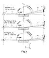
- Figure 3 illustrates the conditions of the light source 20, the incident ray 100, the diffracted ray 200, and the image plane 30 for G 1 to G 3 .
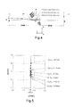
- Figure 4 is a figure illustrating a configuration in which G 1 to G 3 are superposed one upon another in consideration of ⁇ 1 to ⁇ 3 such that the positions of the light source 20 in Figure 3 coincide with one another.
- the grating center of G 1 is set at the lowest position, while the grating center of G 3 is at the highest position (providing a relationship of ⁇ 1 ⁇ 2 ⁇ 3 ).
- the spectroscopic apparatus according to the embodiment of the present invention is configured such that, in switching over among G 1 to G 3 , ⁇ 1 to ⁇ 3 can be utilized for switchover among the angles of incidence corresponding to G 1 to G 3 .
- FIG. 5 depicts the result of calculating a distribution of such focal points when viewed from the same direction as in Figure 4 .
- the focal points are held to within a range as wide as the length of the light receiving surface of a commercially available two-dimensional detector (approx. 25 mm). Therefore, even if a plurality of VLS concave gratings are used in order to cover a wide energy bandwidth, a spectroscopic apparatus having good image formation properties can be obtained.
- n 20 is a parameter relating to the focal point, and it has been indicated that, with the above configuration, the focal point can be kept substantially fixed. Contrarily to this, n 30 and n 40 are parameters relating to the higher aberrations.
- an aspherical wavefront holographic recording method for example, is used. In this case, since the interference of light is utilized to form grating grooves, it is impossible to separately set the n 20 , n 30 , and n 40 . Therefore, the n 20 is set so as to be a predetermined value, and under this condition, the n 30 and n 40 are set to be as appropriate as possible. Accordingly, actually, it is important to make evaluation including the effect of the aberrations as well.
- an aspherical wavefront holographic recording method is disclosed in, for example, Japanese Examined Patent Application Publication No. Hei6-64207 .
- the monochromatic spherical wavefront(s) emitted from two point sources are reflected at both spherical mirrors or only either wavefront is reflected at a spherical mirror to interfere with each other on a photoresist coated on a grating substrate, thereby forming interference fringes.
- the configuration and arrangement of the light source and the spherical mirror are adjusted such that the pattern of the interference fringes provides a desired effective grating constant and groove pattern (VLS grooves).
- VLS grooves desired effective grating constant and groove pattern
- the photoresist is developed for patterning it, and the substrate is etched using the pattern of photoresist as a mask to thereby form a desired groove geometry on the substrate surface.
- a diffraction grating in which grooves are ruled on the substrate itself after being etched is called a master diffraction grating, and replica diffraction gratings having the same groove spacing and groove geometry as those of the master diffraction grating are replicated based on the master grating after the several processing.
- Figures 6 and 7 are figures illustrating two different configurations for use in implementing the aspherical wavefront holographic recording method, the reference characters C and D denoting a laser point source, the M 1 and M 2 spherical mirrors having the radius of curvature of R 1 , R 2 , respectively, and the G here an grating substrate on which interference fringes are to be patterned.
- Figure 8 illustrates the result of examination of the image formation properties of G 2 for five different central wavelengths (3.50 nm, 4.63 nm, 5.75 nm, 6.88 nm, and 8.00 nm).
- the size of the diffraction grating surface was specified to be 50 mm in the y-axis direction and 30 mm in the z-axis direction.
- the aberration causes the spectral image for the respective wavelengths to be expanded in the z-axis direction by approx. 60 mm.
- a commercially available two-dimensional detector such as a CCD, is practicably capable of receiving light and detecting a spectral image up to approx. 10 mm in height.
- G 2 when the throughput is requisite, G 2 may be used, being switched over from G 3 , as appropriate, while the resolution is requisite, G 3 may be used, being switched over from G 2 , as appropriate, depending upon the application.
- G 3 may be used, being switched over from G 2 , as appropriate, depending upon the application.
- the above spectroscopic apparatus allows monochromatic light to be taken out at a high output and a high resolution in a wide wavelength range.
- a selection means which selects one grating from among a plurality of VLS concave gratings, and installs it in a position where an incident ray is to be irradiated, and a diffracted ray (exit ray) is to be taken out.
- the normal line passing through the center of the groove plane of the respective VLS concave gratings is treated as one which is to be superposed upon a common normal line (the x-axis in Figure 1 ).
- the level of the center of the groove plane of the respective VLS gratings in the direction of the x axis varies.
- This level is set in such a manner that the greater the value of the maximum wavelength to be accommodated by the VLS concave grating, the lower the level, and the smaller the value of the maximum wavelength to be accommodated by the varied space concave diffraction grating, the higher the level will be.
- Figure 9 is a figure illustrating a configuration of a spectroscopic apparatus 500 given as a first example that translates G 1 to G 3 in the y-axis direction for making a selection.
- the figure at top in Figure 9 shows a configuration in which G 1 is selected, while the figure at bottom a configuration in which G 2 is selected.
- the light source 20 is located at left in the figure in a place which is not shown, while the image plane 30 at right in the figure in a place which is not shown.
- the coordinate axes (x, y, z) are of the right-handed system.
- the VLS concave gratings G 1 to G 3 are installed, being arranged on a carriage (selection means) 510 in the horizontal direction (the y-axis direction in Figure 1 ).
- the incident ray 100 is directed from the light source 20 to the grating, and the diffracted ray 200 is directed from the grating to the image plane 30.
- the carriage 510 By moving the carriage 510 in the horizontal direction, one of the gratings G 1 to G 3 can be selected.
- the rightmost position of a particular grating provides a position where the VLS concave diffraction grating is to be used.
- the normal line of the groove plane at the grating center thereof is treated as one which is to be superposed upon a common normal line.
- ⁇ 3 ⁇ 3 > ⁇ 2
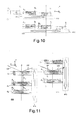
- G 1 to G 3 are arranged and moved in the y-axis direction in Figure 1 , however, as shown in Figure 10 , G1 to G3 may be translated in a direction at right angles to the y-axis direction (the z-axis direction) (a modification of the first example).
- a configuration when the incident ray side (left side) is viewed from the exit ray side (right side) in Figure 1 is shown, and the incident ray and the diffracted ray are not shown, however, these rays are directed from the back side of the surface of the paper toward this side.
- the figure at top shows a configuration in which G 1 has been selected
- the figure at bottom shows a configuration in which G 2 has been selected.
- FIG 11 is a figure illustrating a configuration of a spectroscopic apparatus 600 given as a second example that moves G 1 to G 3 in the vertical direction (x-axis direction) for making a selection.
- the VLS concave gratings G 1 to G 3 are installed, being arranged on a carriage (selection means) 610 in the vertical direction on the side faces thereof.
- the figure at left shows a configuration in which G 1 has been selected
- the figure at right shows a configuration in which G 2 has been selected.
- the incident ray 100 is directed from the light source 20 to the diffraction grating, and the diffracted ray 200 is directed from the diffraction grating to the image plane 30.
- the spacing D 23 between the top face of the G 3 and the bottom face of G 2 can be smaller than the spacing D 12 between the top face of the G 2 and the bottom face of G 1 , whereby the carriage 610 can be made compact.
- the VLS concave gratings are fixed using the carriage 610 such that the normal line passing through the center of the groove plane of the respective diffraction gratings is treated as one which is to be superposed upon a common normal line, and all the diffraction planes are directed upward in a uniformmanner.
- the carriage 610 is set such that it is moved in the direction of this normal line.
- FIG 12 is a figure illustrating a configuration of a spectroscopic apparatus 700 given as a third example that pivots G 1 to G 3 about a pivotal movement center R for making a selection.
- G 1 to G 3 are arranged and installed in different positions on the circumference of a turntable (selection means) 710 which pivots about an axis of pivoting that passes through the pivotal movement center R and is parallel with the z-axis in Figure 1 .
- the figure at top shows a configuration in which G 1 has been selected, while the figure at bottom shows a configuration in which G 2 has been selected.
- the incident ray 100 is directed from the light source 20 to the diffraction grating, and the diffracted ray 200 is directed from the diffraction grating to the image plane 30.
- a switchover among G 1 to G 3 is performed.
- the pivotal axis is parallel with the y-axis in Figure 1 , and around it, G 1 to G 3 are arranged (a modification of the third example).
- G 1 to G 3 are pivoted around the pivotal movement center R with the y-axis direction being used as the pivotal axis.
- the configuration as shown in Figure 12 may cause the optical path (the incident ray and the diffracted ray) to be affected by a diffraction grating adjacent to the diffraction grating selected, however, with the configuration as shown in Figure 13 , such effect will be reduced as is the case with the configuration in Figure 10 .
- the selection means moves G 1 to G 3 within a plane provided in a direction perpendicular to the plane including the incident ray 100 and the diffracted ray 200, thereby one of thembeing selected.
- This movement is a translation one in the modification of the first example, while it is a pivotal one in the modification of the third example.
- VLS concave gratings three types have been used for explanation, however, the number of VLS concave gratings used is optional.
- the varied space concave diffraction grating has been used, however, it is obvious that, even in the case where the grating having a planar geometry is used (in the case where R in Table 1 is equal to ⁇ ), the same advantages can be obtained.
- the traveling mechanism to be used in the horizontal direction (the y-axis direction or the z-axis direction)
- the traveling mechanism to be used in the vertical direction the x-axis direction
- the pivotingmechanism which uses an axis passing through the pivotal movement center R and parallel to the y-axis or z-axis as the pivotal axis have been explained, however, even in the case where these are combined as appropriate, or a mechanism which is different from these, the configuration of the selection means is optional, provided that the same positional relationship as that as described above is implemented in the respective VLS concave gratings.
- the above spectroscopic apparatus is effective regardless of the wavelength, provided that the VLS grating is used.
- the above spectroscopic apparatus is effective especially as a spectroscopic apparatus for the soft x-ray region (the wavelengths of 0.5 to 25 nm) that is used with the angle of incidence ⁇ close to 90°.
- the material constituting the groove plane (diffraction grating surface) of the VLS grating to be used for the soft x-ray region is optional according to the application.
- a single layer deposited film of gold, platinum, nickel, or the like, exhibiting a high reflectivity is effective.
- the multi-layer film structure having a particularly high reflectivity in a specific wavelength range may be used. In that case, a spectroscopic apparatus which can cover the wavelengths shorter than 0.56 nm (the energies higher than 2200 eV) can be obtained.
Landscapes
- Physics & Mathematics (AREA)
- Spectroscopy & Molecular Physics (AREA)
- Engineering & Computer Science (AREA)
- General Engineering & Computer Science (AREA)
- High Energy & Nuclear Physics (AREA)
- Chemical & Material Sciences (AREA)
- Crystallography & Structural Chemistry (AREA)
- Health & Medical Sciences (AREA)
- Life Sciences & Earth Sciences (AREA)
- Analytical Chemistry (AREA)
- Biochemistry (AREA)
- General Health & Medical Sciences (AREA)
- General Physics & Mathematics (AREA)
- Immunology (AREA)
- Pathology (AREA)
- Spectrometry And Color Measurement (AREA)
- Diffracting Gratings Or Hologram Optical Elements (AREA)
Applications Claiming Priority (1)
| Application Number | Priority Date | Filing Date | Title |
|---|---|---|---|
| JP2012087536A JP5948558B2 (ja) | 2012-04-06 | 2012-04-06 | 分光装置 |
Publications (3)
| Publication Number | Publication Date |
|---|---|
| EP2647983A2 true EP2647983A2 (fr) | 2013-10-09 |
| EP2647983A3 EP2647983A3 (fr) | 2017-01-04 |
| EP2647983B1 EP2647983B1 (fr) | 2021-05-26 |
Family
ID=48049748
Family Applications (1)
| Application Number | Title | Priority Date | Filing Date |
|---|---|---|---|
| EP13001723.9A Active EP2647983B1 (fr) | 2012-04-06 | 2013-04-04 | Appareil spectroscopique |
Country Status (3)
| Country | Link |
|---|---|
| US (1) | US8983032B2 (fr) |
| EP (1) | EP2647983B1 (fr) |
| JP (1) | JP5948558B2 (fr) |
Cited By (1)
| Publication number | Priority date | Publication date | Assignee | Title |
|---|---|---|---|---|
| JP2016031271A (ja) * | 2014-07-29 | 2016-03-07 | 日本電子株式会社 | X線分光器の調整方法、x線分光器、および試料分析装置 |
Families Citing this family (5)
| Publication number | Priority date | Publication date | Assignee | Title |
|---|---|---|---|---|
| US10677744B1 (en) * | 2016-06-03 | 2020-06-09 | U.S. Department Of Energy | Multi-cone x-ray imaging Bragg crystal spectrometer |
| DE102017206066A1 (de) * | 2017-04-10 | 2018-10-11 | Anvajo GmbH | Spektrometer |
| US10571334B2 (en) | 2017-12-15 | 2020-02-25 | Horiba Instruments Incorporated | System and method for selective resolution for concave grating spectrometer |
| SG11202005650WA (en) * | 2017-12-21 | 2020-07-29 | Agency Science Tech & Res | 2 dimensional variable line spacing grating based optical spectrometer |
| WO2025150247A1 (fr) * | 2024-01-11 | 2025-07-17 | 株式会社島津製作所 | Spectromètre à rayons x |
Citations (4)
| Publication number | Priority date | Publication date | Assignee | Title |
|---|---|---|---|---|
| JPH0664207B2 (ja) | 1985-04-11 | 1994-08-22 | 株式会社島津製作所 | 回折格子分光器 |
| JP2006133280A (ja) | 2004-11-02 | 2006-05-25 | Japan Atomic Energy Agency | 多層膜不等間隔溝ラミナー型回折格子及び同分光装置 |
| JP2007273477A (ja) | 2001-02-27 | 2007-10-18 | Jeol Ltd | X線分光器を備えた電子顕微鏡 |
| JP2009300303A (ja) | 2008-06-16 | 2009-12-24 | Japan Atomic Energy Agency | 多層膜不等間隔溝ラミナー型回折格子及び同回折格子を用いた分光装置 |
Family Cites Families (8)
| Publication number | Priority date | Publication date | Assignee | Title |
|---|---|---|---|---|
| US5016265A (en) * | 1985-08-15 | 1991-05-14 | The United States Of America As Represented By The Administrator Of The National Aeronautics And Space Administration | Variable magnification variable dispersion glancing incidence imaging x-ray spectroscopic telescope |
| US5274435A (en) * | 1992-02-26 | 1993-12-28 | Hettrick Michael C | Grating monochromators and spectrometers based on surface normal rotation |
| US5280338A (en) * | 1992-10-30 | 1994-01-18 | Oriel Corporation | Multi-grating spectrograph and method of changing gratings |
| JPH1151883A (ja) * | 1997-08-04 | 1999-02-26 | Rigaku Ind Co | 蛍光x線分析装置および方法 |
| JP3624207B2 (ja) * | 1997-08-06 | 2005-03-02 | 理学電機工業株式会社 | 点集束型x線分光装置 |
| JP2002329473A (ja) * | 2001-02-27 | 2002-11-15 | Jeol Ltd | X線分光器を備えた透過型電子顕微鏡 |
| JP3958134B2 (ja) * | 2002-07-12 | 2007-08-15 | キヤノン株式会社 | 測定装置 |
| JP5502644B2 (ja) * | 2010-07-30 | 2014-05-28 | 国立大学法人東北大学 | X線検出システム |
-
2012
- 2012-04-06 JP JP2012087536A patent/JP5948558B2/ja active Active
-
2013
- 2013-04-04 US US13/856,834 patent/US8983032B2/en active Active
- 2013-04-04 EP EP13001723.9A patent/EP2647983B1/fr active Active
Patent Citations (4)
| Publication number | Priority date | Publication date | Assignee | Title |
|---|---|---|---|---|
| JPH0664207B2 (ja) | 1985-04-11 | 1994-08-22 | 株式会社島津製作所 | 回折格子分光器 |
| JP2007273477A (ja) | 2001-02-27 | 2007-10-18 | Jeol Ltd | X線分光器を備えた電子顕微鏡 |
| JP2006133280A (ja) | 2004-11-02 | 2006-05-25 | Japan Atomic Energy Agency | 多層膜不等間隔溝ラミナー型回折格子及び同分光装置 |
| JP2009300303A (ja) | 2008-06-16 | 2009-12-24 | Japan Atomic Energy Agency | 多層膜不等間隔溝ラミナー型回折格子及び同回折格子を用いた分光装置 |
Cited By (1)
| Publication number | Priority date | Publication date | Assignee | Title |
|---|---|---|---|---|
| JP2016031271A (ja) * | 2014-07-29 | 2016-03-07 | 日本電子株式会社 | X線分光器の調整方法、x線分光器、および試料分析装置 |
Also Published As
| Publication number | Publication date |
|---|---|
| JP2013217730A (ja) | 2013-10-24 |
| US8983032B2 (en) | 2015-03-17 |
| EP2647983A3 (fr) | 2017-01-04 |
| US20130266120A1 (en) | 2013-10-10 |
| EP2647983B1 (fr) | 2021-05-26 |
| JP5948558B2 (ja) | 2016-07-06 |
Similar Documents
| Publication | Publication Date | Title |
|---|---|---|
| US8345262B2 (en) | Method and apparatus for determining a deviation of an actual shape from a desired shape of an optical surface | |
| EP2647983B1 (fr) | Appareil spectroscopique | |
| US10488254B2 (en) | Spectrometer with two-dimensional spectrum | |
| US8169703B1 (en) | Monolithic arrays of diffraction gratings | |
| EP3084373B1 (fr) | Spectromètre pour générer un spectre à deux dimensions | |
| JP5170488B2 (ja) | 円錐回折斜入射分光器及び該分光器用回折格子 | |
| CN109974852B (zh) | 快照式光栅光谱仪 | |
| JP7239582B2 (ja) | ポリクロメータシステム及び方法 | |
| CN102052968A (zh) | 一种宽谱段空间外差光谱仪 | |
| JP2760825B2 (ja) | 分光計 | |
| KR101850573B1 (ko) | 미세 회전형 이미지 분광장치 | |
| CN112067126A (zh) | 一种用于大气探测的星载极紫外高光谱相机光学系统 | |
| JP4421683B2 (ja) | ホログラフィ光学系及びモノクロメータの構成を最適化する方法 | |
| CN209727262U (zh) | 一种宽波段高分辨率光谱成像信息同时获取装置 | |
| JP5038963B2 (ja) | 分光光学系および分光測定装置 | |
| CN113607385A (zh) | 一种用于拼接主镜光学系统子镜间位置误差检测系统 | |
| CN110118602B (zh) | 一种宽波段高分辨率光谱成像信息同时获取装置 | |
| CN209102214U (zh) | 基于自由曲面的成像光谱仪 | |
| Allured et al. | Alignment tolerances for off-plane reflection grating spectroscopy: theoretical calculations and laboratory techniques | |
| Ryu et al. | Optics Development for the SPEAR mission | |
| Gulis et al. | Low-aberration imaging monochromator with dispersion subtraction based on an axially symmetric design | |
| Meijer et al. | Ray-tracing of off-axis reflective systems | |
| Hettrick et al. | Interference Methods In The Testing And Fabrication Of New-Design Grazing Incidence Gratings | |
| Wang et al. | Varied line-space plane grating and its ruling experiment | |
| JPH0525291B2 (fr) |
Legal Events
| Date | Code | Title | Description |
|---|---|---|---|
| PUAI | Public reference made under article 153(3) epc to a published international application that has entered the european phase |
Free format text: ORIGINAL CODE: 0009012 |
|
| 17P | Request for examination filed |
Effective date: 20130404 |
|
| AK | Designated contracting states |
Kind code of ref document: A2 Designated state(s): AL AT BE BG CH CY CZ DE DK EE ES FI FR GB GR HR HU IE IS IT LI LT LU LV MC MK MT NL NO PL PT RO RS SE SI SK SM TR |
|
| AX | Request for extension of the european patent |
Extension state: BA ME |
|
| PUAL | Search report despatched |
Free format text: ORIGINAL CODE: 0009013 |
|
| AK | Designated contracting states |
Kind code of ref document: A3 Designated state(s): AL AT BE BG CH CY CZ DE DK EE ES FI FR GB GR HR HU IE IS IT LI LT LU LV MC MK MT NL NO PL PT RO RS SE SI SK SM TR |
|
| AX | Request for extension of the european patent |
Extension state: BA ME |
|
| RIC1 | Information provided on ipc code assigned before grant |
Ipc: G21K 1/06 20060101ALI20161129BHEP Ipc: G01N 23/20 20060101AFI20161129BHEP |
|
| STAA | Information on the status of an ep patent application or granted ep patent |
Free format text: STATUS: EXAMINATION IS IN PROGRESS |
|
| 17Q | First examination report despatched |
Effective date: 20200414 |
|
| GRAP | Despatch of communication of intention to grant a patent |
Free format text: ORIGINAL CODE: EPIDOSNIGR1 |
|
| STAA | Information on the status of an ep patent application or granted ep patent |
Free format text: STATUS: GRANT OF PATENT IS INTENDED |
|
| INTG | Intention to grant announced |
Effective date: 20201124 |
|
| GRAS | Grant fee paid |
Free format text: ORIGINAL CODE: EPIDOSNIGR3 |
|
| RAP1 | Party data changed (applicant data changed or rights of an application transferred) |
Owner name: JEOL LTD. Owner name: NATIONAL INSTITUTES FOR QUANTUM AND RADIOLOGICAL SCIENCE AND TECHNOLOGY Owner name: TOHOKU UNIVERSITY Owner name: SHIMADZU CORPORATION |
|
| GRAA | (expected) grant |
Free format text: ORIGINAL CODE: 0009210 |
|
| STAA | Information on the status of an ep patent application or granted ep patent |
Free format text: STATUS: THE PATENT HAS BEEN GRANTED |
|
| AK | Designated contracting states |
Kind code of ref document: B1 Designated state(s): AL AT BE BG CH CY CZ DE DK EE ES FI FR GB GR HR HU IE IS IT LI LT LU LV MC MK MT NL NO PL PT RO RS SE SI SK SM TR |
|
| REG | Reference to a national code |
Ref country code: GB Ref legal event code: FG4D |
|
| REG | Reference to a national code |
Ref country code: CH Ref legal event code: EP |
|
| REG | Reference to a national code |
Ref country code: AT Ref legal event code: REF Ref document number: 1396726 Country of ref document: AT Kind code of ref document: T Effective date: 20210615 |
|
| REG | Reference to a national code |
Ref country code: DE Ref legal event code: R096 Ref document number: 602013077625 Country of ref document: DE |
|
| REG | Reference to a national code |
Ref country code: IE Ref legal event code: FG4D |
|
| REG | Reference to a national code |
Ref country code: LT Ref legal event code: MG9D |
|
| REG | Reference to a national code |
Ref country code: AT Ref legal event code: MK05 Ref document number: 1396726 Country of ref document: AT Kind code of ref document: T Effective date: 20210526 |
|
| PG25 | Lapsed in a contracting state [announced via postgrant information from national office to epo] |
Ref country code: LT Free format text: LAPSE BECAUSE OF FAILURE TO SUBMIT A TRANSLATION OF THE DESCRIPTION OR TO PAY THE FEE WITHIN THE PRESCRIBED TIME-LIMIT Effective date: 20210526 Ref country code: FI Free format text: LAPSE BECAUSE OF FAILURE TO SUBMIT A TRANSLATION OF THE DESCRIPTION OR TO PAY THE FEE WITHIN THE PRESCRIBED TIME-LIMIT Effective date: 20210526 Ref country code: BG Free format text: LAPSE BECAUSE OF FAILURE TO SUBMIT A TRANSLATION OF THE DESCRIPTION OR TO PAY THE FEE WITHIN THE PRESCRIBED TIME-LIMIT Effective date: 20210826 Ref country code: AT Free format text: LAPSE BECAUSE OF FAILURE TO SUBMIT A TRANSLATION OF THE DESCRIPTION OR TO PAY THE FEE WITHIN THE PRESCRIBED TIME-LIMIT Effective date: 20210526 Ref country code: HR Free format text: LAPSE BECAUSE OF FAILURE TO SUBMIT A TRANSLATION OF THE DESCRIPTION OR TO PAY THE FEE WITHIN THE PRESCRIBED TIME-LIMIT Effective date: 20210526 |
|
| REG | Reference to a national code |
Ref country code: NL Ref legal event code: MP Effective date: 20210526 |
|
| PG25 | Lapsed in a contracting state [announced via postgrant information from national office to epo] |
Ref country code: SE Free format text: LAPSE BECAUSE OF FAILURE TO SUBMIT A TRANSLATION OF THE DESCRIPTION OR TO PAY THE FEE WITHIN THE PRESCRIBED TIME-LIMIT Effective date: 20210526 Ref country code: RS Free format text: LAPSE BECAUSE OF FAILURE TO SUBMIT A TRANSLATION OF THE DESCRIPTION OR TO PAY THE FEE WITHIN THE PRESCRIBED TIME-LIMIT Effective date: 20210526 Ref country code: LV Free format text: LAPSE BECAUSE OF FAILURE TO SUBMIT A TRANSLATION OF THE DESCRIPTION OR TO PAY THE FEE WITHIN THE PRESCRIBED TIME-LIMIT Effective date: 20210526 Ref country code: GR Free format text: LAPSE BECAUSE OF FAILURE TO SUBMIT A TRANSLATION OF THE DESCRIPTION OR TO PAY THE FEE WITHIN THE PRESCRIBED TIME-LIMIT Effective date: 20210827 Ref country code: IS Free format text: LAPSE BECAUSE OF FAILURE TO SUBMIT A TRANSLATION OF THE DESCRIPTION OR TO PAY THE FEE WITHIN THE PRESCRIBED TIME-LIMIT Effective date: 20210926 Ref country code: NO Free format text: LAPSE BECAUSE OF FAILURE TO SUBMIT A TRANSLATION OF THE DESCRIPTION OR TO PAY THE FEE WITHIN THE PRESCRIBED TIME-LIMIT Effective date: 20210826 Ref country code: PT Free format text: LAPSE BECAUSE OF FAILURE TO SUBMIT A TRANSLATION OF THE DESCRIPTION OR TO PAY THE FEE WITHIN THE PRESCRIBED TIME-LIMIT Effective date: 20210927 Ref country code: PL Free format text: LAPSE BECAUSE OF FAILURE TO SUBMIT A TRANSLATION OF THE DESCRIPTION OR TO PAY THE FEE WITHIN THE PRESCRIBED TIME-LIMIT Effective date: 20210526 |
|
| PG25 | Lapsed in a contracting state [announced via postgrant information from national office to epo] |
Ref country code: NL Free format text: LAPSE BECAUSE OF FAILURE TO SUBMIT A TRANSLATION OF THE DESCRIPTION OR TO PAY THE FEE WITHIN THE PRESCRIBED TIME-LIMIT Effective date: 20210526 |
|
| PG25 | Lapsed in a contracting state [announced via postgrant information from national office to epo] |
Ref country code: SK Free format text: LAPSE BECAUSE OF FAILURE TO SUBMIT A TRANSLATION OF THE DESCRIPTION OR TO PAY THE FEE WITHIN THE PRESCRIBED TIME-LIMIT Effective date: 20210526 Ref country code: SM Free format text: LAPSE BECAUSE OF FAILURE TO SUBMIT A TRANSLATION OF THE DESCRIPTION OR TO PAY THE FEE WITHIN THE PRESCRIBED TIME-LIMIT Effective date: 20210526 Ref country code: EE Free format text: LAPSE BECAUSE OF FAILURE TO SUBMIT A TRANSLATION OF THE DESCRIPTION OR TO PAY THE FEE WITHIN THE PRESCRIBED TIME-LIMIT Effective date: 20210526 Ref country code: DK Free format text: LAPSE BECAUSE OF FAILURE TO SUBMIT A TRANSLATION OF THE DESCRIPTION OR TO PAY THE FEE WITHIN THE PRESCRIBED TIME-LIMIT Effective date: 20210526 Ref country code: CZ Free format text: LAPSE BECAUSE OF FAILURE TO SUBMIT A TRANSLATION OF THE DESCRIPTION OR TO PAY THE FEE WITHIN THE PRESCRIBED TIME-LIMIT Effective date: 20210526 Ref country code: RO Free format text: LAPSE BECAUSE OF FAILURE TO SUBMIT A TRANSLATION OF THE DESCRIPTION OR TO PAY THE FEE WITHIN THE PRESCRIBED TIME-LIMIT Effective date: 20210526 Ref country code: ES Free format text: LAPSE BECAUSE OF FAILURE TO SUBMIT A TRANSLATION OF THE DESCRIPTION OR TO PAY THE FEE WITHIN THE PRESCRIBED TIME-LIMIT Effective date: 20210526 |
|
| REG | Reference to a national code |
Ref country code: DE Ref legal event code: R097 Ref document number: 602013077625 Country of ref document: DE |
|
| PLBE | No opposition filed within time limit |
Free format text: ORIGINAL CODE: 0009261 |
|
| STAA | Information on the status of an ep patent application or granted ep patent |
Free format text: STATUS: NO OPPOSITION FILED WITHIN TIME LIMIT |
|
| 26N | No opposition filed |
Effective date: 20220301 |
|
| PG25 | Lapsed in a contracting state [announced via postgrant information from national office to epo] |
Ref country code: IS Free format text: LAPSE BECAUSE OF FAILURE TO SUBMIT A TRANSLATION OF THE DESCRIPTION OR TO PAY THE FEE WITHIN THE PRESCRIBED TIME-LIMIT Effective date: 20210926 Ref country code: AL Free format text: LAPSE BECAUSE OF FAILURE TO SUBMIT A TRANSLATION OF THE DESCRIPTION OR TO PAY THE FEE WITHIN THE PRESCRIBED TIME-LIMIT Effective date: 20210526 |
|
| PG25 | Lapsed in a contracting state [announced via postgrant information from national office to epo] |
Ref country code: IT Free format text: LAPSE BECAUSE OF FAILURE TO SUBMIT A TRANSLATION OF THE DESCRIPTION OR TO PAY THE FEE WITHIN THE PRESCRIBED TIME-LIMIT Effective date: 20210526 |
|
| REG | Reference to a national code |
Ref country code: CH Ref legal event code: PL |
|
| GBPC | Gb: european patent ceased through non-payment of renewal fee |
Effective date: 20220404 |
|
| REG | Reference to a national code |
Ref country code: BE Ref legal event code: MM Effective date: 20220430 |
|
| PG25 | Lapsed in a contracting state [announced via postgrant information from national office to epo] |
Ref country code: MC Free format text: LAPSE BECAUSE OF FAILURE TO SUBMIT A TRANSLATION OF THE DESCRIPTION OR TO PAY THE FEE WITHIN THE PRESCRIBED TIME-LIMIT Effective date: 20210526 Ref country code: LU Free format text: LAPSE BECAUSE OF NON-PAYMENT OF DUE FEES Effective date: 20220404 Ref country code: LI Free format text: LAPSE BECAUSE OF NON-PAYMENT OF DUE FEES Effective date: 20220430 Ref country code: GB Free format text: LAPSE BECAUSE OF NON-PAYMENT OF DUE FEES Effective date: 20220404 Ref country code: CH Free format text: LAPSE BECAUSE OF NON-PAYMENT OF DUE FEES Effective date: 20220430 |
|
| PG25 | Lapsed in a contracting state [announced via postgrant information from national office to epo] |
Ref country code: BE Free format text: LAPSE BECAUSE OF NON-PAYMENT OF DUE FEES Effective date: 20220430 |
|
| PG25 | Lapsed in a contracting state [announced via postgrant information from national office to epo] |
Ref country code: IE Free format text: LAPSE BECAUSE OF NON-PAYMENT OF DUE FEES Effective date: 20220404 |
|
| PG25 | Lapsed in a contracting state [announced via postgrant information from national office to epo] |
Ref country code: HU Free format text: LAPSE BECAUSE OF FAILURE TO SUBMIT A TRANSLATION OF THE DESCRIPTION OR TO PAY THE FEE WITHIN THE PRESCRIBED TIME-LIMIT; INVALID AB INITIO Effective date: 20130404 |
|
| PG25 | Lapsed in a contracting state [announced via postgrant information from national office to epo] |
Ref country code: MK Free format text: LAPSE BECAUSE OF FAILURE TO SUBMIT A TRANSLATION OF THE DESCRIPTION OR TO PAY THE FEE WITHIN THE PRESCRIBED TIME-LIMIT Effective date: 20210526 Ref country code: CY Free format text: LAPSE BECAUSE OF FAILURE TO SUBMIT A TRANSLATION OF THE DESCRIPTION OR TO PAY THE FEE WITHIN THE PRESCRIBED TIME-LIMIT Effective date: 20210526 |
|
| PG25 | Lapsed in a contracting state [announced via postgrant information from national office to epo] |
Ref country code: MT Free format text: LAPSE BECAUSE OF FAILURE TO SUBMIT A TRANSLATION OF THE DESCRIPTION OR TO PAY THE FEE WITHIN THE PRESCRIBED TIME-LIMIT Effective date: 20210526 |
|
| PGFP | Annual fee paid to national office [announced via postgrant information from national office to epo] |
Ref country code: DE Payment date: 20250305 Year of fee payment: 13 |
|
| PG25 | Lapsed in a contracting state [announced via postgrant information from national office to epo] |
Ref country code: TR Free format text: LAPSE BECAUSE OF FAILURE TO SUBMIT A TRANSLATION OF THE DESCRIPTION OR TO PAY THE FEE WITHIN THE PRESCRIBED TIME-LIMIT Effective date: 20210526 |
|
| PGFP | Annual fee paid to national office [announced via postgrant information from national office to epo] |
Ref country code: FR Payment date: 20260309 Year of fee payment: 14 |