EP2648021A1 - Procédé et dispositif pour détecter des défauts dans un réseau de sources marines - Google Patents
Procédé et dispositif pour détecter des défauts dans un réseau de sources marines Download PDFInfo
- Publication number
- EP2648021A1 EP2648021A1 EP13161867.0A EP13161867A EP2648021A1 EP 2648021 A1 EP2648021 A1 EP 2648021A1 EP 13161867 A EP13161867 A EP 13161867A EP 2648021 A1 EP2648021 A1 EP 2648021A1
- Authority
- EP
- European Patent Office
- Prior art keywords
- wave sources
- individual
- individual wave
- index
- sensors
- Prior art date
- Legal status (The legal status is an assumption and is not a legal conclusion. Google has not performed a legal analysis and makes no representation as to the accuracy of the status listed.)
- Withdrawn
Links
Images


Classifications
-
- G—PHYSICS
- G01—MEASURING; TESTING
- G01V—GEOPHYSICS; GRAVITATIONAL MEASUREMENTS; DETECTING MASSES OR OBJECTS; TAGS
- G01V1/00—Seismology; Seismic or acoustic prospecting or detecting
- G01V1/02—Generating seismic energy
- G01V1/133—Generating seismic energy using fluidic driving means, e.g. highly pressurised fluids; using implosion
- G01V1/137—Generating seismic energy using fluidic driving means, e.g. highly pressurised fluids; using implosion which fluid escapes from the generator in a pulsating manner, e.g. for generating bursts, airguns
-
- G—PHYSICS
- G01—MEASURING; TESTING
- G01V—GEOPHYSICS; GRAVITATIONAL MEASUREMENTS; DETECTING MASSES OR OBJECTS; TAGS
- G01V1/00—Seismology; Seismic or acoustic prospecting or detecting
- G01V1/38—Seismology; Seismic or acoustic prospecting or detecting specially adapted for water-covered areas
-
- G—PHYSICS
- G01—MEASURING; TESTING
- G01V—GEOPHYSICS; GRAVITATIONAL MEASUREMENTS; DETECTING MASSES OR OBJECTS; TAGS
- G01V1/00—Seismology; Seismic or acoustic prospecting or detecting
- G01V1/38—Seismology; Seismic or acoustic prospecting or detecting specially adapted for water-covered areas
- G01V1/3817—Positioning of seismic devices
- G01V1/3835—Positioning of seismic devices measuring position, e.g. by GPS or acoustically
-
- G—PHYSICS
- G01—MEASURING; TESTING
- G01V—GEOPHYSICS; GRAVITATIONAL MEASUREMENTS; DETECTING MASSES OR OBJECTS; TAGS
- G01V1/00—Seismology; Seismic or acoustic prospecting or detecting
- G01V1/38—Seismology; Seismic or acoustic prospecting or detecting specially adapted for water-covered areas
- G01V1/3861—Seismology; Seismic or acoustic prospecting or detecting specially adapted for water-covered areas control of source arrays, e.g. for far field control
-
- G—PHYSICS
- G01—MEASURING; TESTING
- G01V—GEOPHYSICS; GRAVITATIONAL MEASUREMENTS; DETECTING MASSES OR OBJECTS; TAGS
- G01V2200/00—Details of seismic or acoustic prospecting or detecting in general
- G01V2200/10—Miscellaneous details
- G01V2200/14—Quality control
-
- G—PHYSICS
- G01—MEASURING; TESTING
- G01V—GEOPHYSICS; GRAVITATIONAL MEASUREMENTS; DETECTING MASSES OR OBJECTS; TAGS
- G01V2210/00—Details of seismic processing or analysis
- G01V2210/10—Aspects of acoustic signal generation or detection
- G01V2210/12—Signal generation
- G01V2210/121—Active source
- G01V2210/1212—Shot
Definitions
- Embodiments of the subject matter disclosed herein generally relate to methods and devices for determining a fault (such as a delay or an air leak in an air gun) of individual pressure wave sources of a marine source array based on near-field data acquired by pressure sensors placed near each of the individual pressure wave sources.
- a fault such as a delay or an air leak in an air gun
- Marine seismic surveys acquire and process data to generate a profile (image) of the geophysical structure under the seafloor. While this profile does not provide an accurate location for oil and gas, it suggests, to those trained in the field, the presence or absence of oil and/or gas.
- a vessel tows a seismic wave source and detectors (wave receivers) located on streamers. Reflections of the source-generated waves are recorded by detectors. The waves are reflected interfaces between layers, when the density and the wave velocity change (e.g., at an interface between water and air, water to rock, shale to sand, etc).
- a popular seismic wave source is the air gun.
- An air gun stores compressed air and releases it suddenly underwater when fired.
- the released air forms a bubble (which may be considered spherical), with air pressure inside the bubble initially greatly exceeding the hydrostatic pressure in the surrounding water.
- the bubble expands, displacing the water and causing a pressure disturbance that travels through the water.
- the pressure decreases, eventually becoming lower than the hydrostatic pressure.
- the bubble begins to contract until the pressure inside again becomes larger than the hydrostatic pressure.
- the process of expansion and contraction may continue through many cycles, thereby generating a pressure (i.e., seismic) wave.
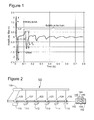
- the pressure variation generated in the water by a single source (which can be measured using a hydrophone or geophone located near the air gun) as a function of time is called the air gun signature and is illustrated in Figure 1 .
- a first pressure increase due to the released air is called primary pulse and it is followed by a pressure drop known as a ghost. Between highest primary pressure and lowest ghost pressure there is a peak pressure variation (P-P).
- the pulses following the primary and the ghost are known as a bubble pulse train.
- the pressure difference between the second pair of high and low pressures is a bubble pressure variation P b -P b .
- the time T between pulses is the bubble period.
- a parameter evaluated based on the signature is the peak-to-bubble ratio, which is P-P/ P b -P b .
- Single air guns are not practical because they do not produce enough energy to penetrate at desired depths under the seafloor, and plural weak oscillations (i.e., the bubble pulse train) following the primary (first) pulse complicates seismic data processing. These problems are overcome by using arrays of air guns, generating a larger amplitude primary pulse and canceling secondary individual pulses by destructive interference.
- Figure 1 represents a situation in which the bubble generated by a single air gun drifts slowly toward the surface, surrounded by water having the hydrostatic pressure constant or slowly varying as the bubble slowly drifts upward. However, when another air gun is fired simultaneously in proximity to the first air gun, the hydrostatic pressure is no longer constant or slowly varying. The bubbles of neighboring guns affect each other.
- a source array includes plural individual wave sources.
- An individual wave source may be an air gun or a cluster of air guns. Since the dimensions of the source array, including plural individual sources, are comparable with the wavelengths of generated wave, the wave generated by the source array is directional, i.e., the shape of the wave, or the signature varies with the direction until, at a great enough distance, the wave starts having a stable shape. After the shape become stable, the amplitude of the wave decreases inversely proportional to the distance. The region where the signature shape no longer changes significantly with distance is known as the "far-field,” in contrast to the "near-field" region where the shape varies. Knowledge of the wave source's far-field signature is desirable in order to extract information about the geological structure generating the detected wave upon receiving the far-field input wave.
- an equivalent notional signature for each individual source may be calculated for each of the guns using near-field measurements (see e.g., U.S. Patent No. 4,476,553 incorporated herewith by reference).
- the equivalent notional signature is a representation of amplitude due to an individual wave source as a function of time, the source array's far-field signature being a superposition of the notional signatures corresponding to each of the individual sources.
- the equivalent notional signature is a tool for representing the contribution of an individual source to the far-field signature, such that the individual source contribution is decoupled from contributions of other individual wave sources in the source array.
- the stability and reliability of the far-field signature depends on the stability of each of the individual wave sources and of the source array's geometry.
- the individual wave sources' behavior may change (e.g., firing later or earlier than expected, than desirable, or at a smaller amplitude than nominally designed) and thus affect the far-field source signature.
- Embodiments of the present inventive concept allow identifying faults of individual wave sources of a marine source array based on the near-field data. These embodiments enable an operator to make informed decisions or to implement corrective actions related to the individual wave sources of a marine source array.
- a method for detecting faults of individual wave sources in a marine source array includes acquiring near-field data using sensors, the sensors being located near the individual wave sources. The method further includes generating an index for each of the individual wave sources based on (A) the near-field data and (B) information on geometry of the marine source array that enables localizing the individual wave sources and respective sensors relative to one another. The method also includes comparing the index for each of the individual wave sources with a corresponding reference index for determining whether a fault has occurred.
- a marine source array evaluation apparatus configured to analyze data related to a marine source array, including individual pressure wave sources configured to generate waves underwater, and sensors associated with the individual wave sources configured to acquire near-field data related to the waves generated by the individual wave sources, the sensors being placed near the individual wave sources.
- the apparatus includes a near-field data processing unit configured to generate an index for each of the individual wave sources based on (A) the near-field data and (B) information on geometry of the marine source array that enables localizing (i) the individual wave sources and (ii) respective sensors relative to one another.
- the near-field data processing unit is further configured to compare the index for each of the individual wave sources with a corresponding reference index for determining whether a fault has occurred.
- a computer readable media non-transitorily storing executable codes which when executed on a computer make the computer perform a method for detecting individual source faults in a marine source array.
- the method includes includes acquiring near-field data using sensors, the sensors being located near the individual wave sources.
- the method further includes generating an index for each of the individual wave sources based on (A) the near-field data and (B) information on geometry of the marine source array that enables localizing the individual wave sources and respective sensors relative to one another.
- the method also includes comparing the index for each of the individual wave sources with a corresponding reference index for determining whether a fault has occurred.
- Figure 1 is a graph illustrating pressure variation in time when a gun fires
- Figure 2 illustrates a marine source array and a seismic data processing unit according to an exemplary embodiment
- Figure 3 is a flowchart illustrating steps performed by a method for detecting faults of individual wave sources in a marine source array, according to an exemplary embodiment
- Figure 4 is a graph exemplarily illustrating angular dependence of the reflection coefficient used in one embodiment
- Figures 5A and 5B illustrate nominal design values of individual wave source positions (squares) for two separate source sub-arrays and wave source positions (stars) as estimated using the near-field data.
- Figure 6 illustrates a gun source array used for testing a method according to an exemplary embodiment
- Figure 7 is the inverted notional for a normal situation and for a situation in which some of the individual wave sources were intentionally delayed;
- Figure 8 illustrates the delays of individual wave sources obtained for the situation in which some of the individual wave sources were intentionally delayed.
- Figure 9 is a data processing flow according to an exemplary embodiment.
- Figure 2 illustrates a marine source array 100 including individual sources 110, 111, 112, 113, 114, 115 and sensors 120, 121, 122, 123, 124, 125 located near (above) the individual sources 110-115, respectively.
- the sensors 120-125 may be hydrophones or geophones. The number and arrangement of the individual sources are merely exemplary and are not intended to be limiting.
- Each of the individual wave sources 110-115 may be a single air gun or a cluster of air guns.
- the sensors 120-125 may be at about 1 m above the individual wave sources 110-115.
- the distance in-between neighboring individual wave sources may be about 3 m.
- the marine source array 100 may include also a soft float 130.
- the sensors 120-125 are connected to a seismic data processing unit 140 (e.g., located on the towing vessel), including an interface 142, a processor 144 and a memory 146.
- the seismic data processing unit 140 may also include a monitoring unit 148 and a display 150.
- the interface 142 receives the near-field seismic data from the sensors 120-125 and provides this data to the processor 144 and/or stores the data in the memory 146.
- the processor 144 is configured to generate an index for each of the individual wave sources based on (A) the near-field data and (B) information on the geometry of the marine source array that enables localizing (i) the individual wave sources and (ii) respective sensors relative to one another.
- the information about the geometry of the marine source array 100 may be based on nominal values stored in the memory 146 and updated by the processor 144 based on current position indications. For example, the current position indications may be received or inferred based on acoustic equipment, GPS equipment and/or the near-field seismic data.
- the memory 146 may store information recorded prior to performing the seismic survey.
- the memory 146 may store results of a bubble test that allows determination of the wave reflection coefficient at the water surface as a function of the incident angle.
- the processor 144 may determine characteristics of filters associated with the sensors 120-125. These filters are used to compensate for inherent differences between the sensors related to amplitude, phase, hardware, etc. The characteristics of these filters may be determined based on a comparison between the near-field signatures on the individual wave sources which were recorded during bubble tests. The purpose of the bubble test is to verify that the each individual source of a source array performs at nominal values. During the bubble test, the correct pressure, tow depth, timing and volume of each individual gun are verified.
- the far-field signature of the source array 100 may be unstable because of horizontal and vertical geometry variations due to the waves and currents.
- the signature of the air gun source array 100 is evaluated for positions substantially vertically underneath the air gun source array 100.
- the far-field signature may also be unstable when notch locations (where the wave traveling directly from the source and the water-surface-reflected wave interfere destructively, canceling each other) fluctuate due to the time variation of the thickness of the water layer between the source and the surface and angle dependency of the reflection coefficient.
- the signature of the air gun source array 100 may be also unstable due to delays or faults of the individual sources, for example when the sources do not fire at the same time.
- Conventional methods of determining the far-field signature of a source array are not configured to take into consideration the above-discussed causes of far-field signature instability.
- the processor 144 is configured to perform methods for detecting faults of individual wave sources in a marine source array.
- the processor 144 may perform these methods using executable codes stored in the memory 146 or in other computer-readable storage media.
- the method 200 includes acquiring near-field data using sensors (one of the sensors being located near each individual wave source), at S210.
- the method 200 includes generating an index for each of the individual wave sources based on (A) the near-field data and (B) information on the geometry of the marine source array, at S220. This information enables localizing (i) the individual wave sources and (ii) respective sensors relative to one another.
- the method 200 also includes comparing the generated index with a reference index for each of the individual wave sources for determining whether a fault has occurred, at S230.
- Generating the index for each individual wave source may include determining an equivalent notional signature for each of the individual wave sources and extracting the index based on an inverse of the equivalent notional signature.
- the term "inverse of a notional” indicates that the notional is retrieved from near-field data using an inversion method.
- FIG. 4 An exemplary embodiment of the reflection coefficient as a function of the incident angle is illustrated in Figure 4 .
- the reflection coefficient is one of the parameters used in the inversion algorithm. Unlike in the conventional approach in which this reflection coefficient is assumed constant and equal with -1 (i.e., the "dipole" or "mirror image” approach), methods according to various embodiments use a more realistic approach, taking into consideration the incident angle dependence of the water to air reflection coefficient.
- line 300 represents a function obtained by interpolating averages of measured or calculated reflection coefficient values, as determined during bubble tests. Another functional fit may be used instead of interpolation.
- nominal design values may be altered based on information acquired using acoustic equipment or GPS equipment, or even using the near-field data.
- the dynamic gun positions may be estimated by inversion of near-field hydrophone records.
- Figures 5A and 5B illustrate nominal design values of individual wave source positions (the full black circles) for two separate source sub-arrays and wave source positions (the white circles) as estimated using the near-field data.
- the source sub-arrays are labeled as starboard source and port source. These source sub-arrays may be fired simultaneously or sequentially.
- the "in-line” direction corresponds to the towing direction, and the "cross-line” corresponds to a direction perpendicular to the towing direction.
- the individual source position precision achieved by determining the actual position using near-field data is significantly better ( ⁇ 0.2 m) than when using nominal values or even GPS equipment (2-3 m precision).
- the index generated for each individual wave source from the inverse notional signature may be an arrival time of a first peak, a spectrum, a phase, a peak-to-bubble ratio, and a bubble period.
- FIG. 6 illustrates a gun source array used for testing a method according to an exemplary embodiment.
- the total volume of this source is about 3,500 cubic inches.
- the white icons represent an individual wave source including a single air gun, the black icons correspond to inactive air guns, and the grey icons correspond to a cluster of air guns.
- the x-axis is "in-line" with the towing direction, and the y-axis is a direction perpendicular to the towing direction.
- Figure 7 is a graph illustrating amplitude of pressure versus time due to a source array fired for two situations: the continuous line 710 corresponds to the inverted notional for a normal situation (when the guns are fired simultaneously), and the dashed line 720 corresponds to a situation in which guns 2, 4, 5, 14, 15 and 16 in Figure 6 are delayed about 2 ms.
- An arrival time of the first peak for each individual wave source is determined based on the near-field data and information on geometry of the marine source array in the second situation.
- Figure 8 illustrates the delay versus gun number obtained by applying this method according to an embodiment. Thus, the 2 ms delays of guns 2, 4, 5, 14, 15 and 16 were correctly identified.
- An air leak of air gun may be detected when a bubble period of the inverted notional signature of the individual wave source significantly departs from a reference value thereof.
- a monitoring unit 148 may be included in the seismic data processing unit 140 and be connected to the processor 144. This monitoring unit 148 may be configured to monitor the evolution of the index for each of the individual sources and to signal when a difference between the generated index and the reference index exceeds a predetermined index threshold difference.
- the seismic data processing unit 140 may also include a display 150 connected to the processor 144 and configured to display values of the index versus time for one or more of the individual wave sources.
- Figure 9 is a data processing flow according to another embodiment.
- the near-field data is recorded.
- the near-field data is calibrated by applying filters to remove any bias due to the individual sensors (hydrophones).
- the actual hydrophones and air guns' positions are asserted at S930, using the near-field data itself or other information such as that provided by GPS or acoustic equipment.
- near-field data inversion is performed to obtain notional signatures.
- an index is generated for each air gun based on the respective notional signature at S950.
- Each index is then compared with a corresponding reference value at S960.
- the disclosed exemplary embodiments provide methods and a system using near-field data to determine faults of individual wave sources of a marine source array. It should be understood that this description is not intended to limit the invention. On the contrary, the exemplary embodiments are intended to cover alternatives, modifications and equivalents, which are included in the spirit and scope of the invention as defined by the appended claims. Further, in the detailed description of the exemplary embodiments, numerous specific details are set forth in order to provide a comprehensive understanding of the claimed invention. However, one skilled in the art would understand that various embodiments may be practiced without such specific details.
- the exemplary embodiments may combine hardware and software aspects.
- the exemplary embodiments may take the form of a computer-readable storage medium non-transitorily storing executable codes (i.e., a computer program) which when executed on a computer perform the above-described methods.
- Any suitable computer-readable medium may be utilized, including hard disks, CD-ROMs, digital versatile disc (DVD), optical storage devices, or magnetic storage devices such a floppy disk or magnetic tape.
- Other non-limiting examples of computer-readable media include flash-type memories or other known memories.
Landscapes
- Life Sciences & Earth Sciences (AREA)
- Physics & Mathematics (AREA)
- Remote Sensing (AREA)
- Engineering & Computer Science (AREA)
- Geology (AREA)
- Environmental & Geological Engineering (AREA)
- Acoustics & Sound (AREA)
- General Life Sciences & Earth Sciences (AREA)
- General Physics & Mathematics (AREA)
- Geophysics (AREA)
- Oceanography (AREA)
- Geophysics And Detection Of Objects (AREA)
- Measurement Of Velocity Or Position Using Acoustic Or Ultrasonic Waves (AREA)
Applications Claiming Priority (1)
| Application Number | Priority Date | Filing Date | Title |
|---|---|---|---|
| US201261619003P | 2012-04-02 | 2012-04-02 |
Publications (1)
| Publication Number | Publication Date |
|---|---|
| EP2648021A1 true EP2648021A1 (fr) | 2013-10-09 |
Family
ID=47998314
Family Applications (1)
| Application Number | Title | Priority Date | Filing Date |
|---|---|---|---|
| EP13161867.0A Withdrawn EP2648021A1 (fr) | 2012-04-02 | 2013-03-29 | Procédé et dispositif pour détecter des défauts dans un réseau de sources marines |
Country Status (5)
| Country | Link |
|---|---|
| US (1) | US9405025B2 (fr) |
| EP (1) | EP2648021A1 (fr) |
| AU (1) | AU2013202657B2 (fr) |
| BR (1) | BR102013007834A2 (fr) |
| MX (1) | MX2013003726A (fr) |
Cited By (2)
| Publication number | Priority date | Publication date | Assignee | Title |
|---|---|---|---|---|
| GB2515395A (en) * | 2013-05-15 | 2014-12-24 | Pgs Geophysical As | Time-efficient tests to detect air gun faults |
| US9482766B2 (en) | 2013-05-15 | 2016-11-01 | Pgs Geophysical As | Time-efficient tests to detect air gun faults |
Families Citing this family (6)
| Publication number | Priority date | Publication date | Assignee | Title |
|---|---|---|---|---|
| EP3117246A2 (fr) | 2014-03-14 | 2017-01-18 | CGG Services SA | Procédé et appareil d'estimation de signature source en eaux peu profondes |
| WO2016083892A2 (fr) | 2014-11-25 | 2016-06-02 | Cgg Services Sa | Estimation d'un signal variable dans le temps représentant une source sismique |
| WO2016193825A1 (fr) | 2015-06-02 | 2016-12-08 | Cgg Services Sa | Procédé, système et dispositif de commande d'étalonnage pour source à niveau multiple |
| WO2016207720A1 (fr) * | 2015-06-22 | 2016-12-29 | Cgg Services Sa | Procédé d'étalonnage de la position d'un élément de mise à feu |
| CN105301633B (zh) * | 2015-10-23 | 2017-07-07 | 中国石油天然气集团公司 | 地震勘探作业中查线信息的传输方法和装置 |
| CN106324703A (zh) * | 2016-08-08 | 2017-01-11 | 中国石油天然气集团公司 | 检测气枪故障的方法及系统 |
Citations (7)
| Publication number | Priority date | Publication date | Assignee | Title |
|---|---|---|---|---|
| US4476553A (en) | 1981-05-29 | 1984-10-09 | The British National Oil Corporation | Method of determining the signatures of arrays of marine seismic sources |
| US20050259513A1 (en) * | 2004-05-20 | 2005-11-24 | Parkes Gregory E | Method of seismic source monitoring using modeled source signatures with calibration functions |
| US20070258322A1 (en) * | 2005-12-23 | 2007-11-08 | Westerngeco L.L.C. | Methods and systems for determining signatures for arrays of marine seismic sources for seismic analysis |
| US20080175102A1 (en) * | 2007-01-19 | 2008-07-24 | Stian Hegna | Method for detecting air gun faults in a marine seismic source array |
| EP2322955A2 (fr) * | 2002-03-14 | 2011-05-18 | ION Geophysical Corporation | Procédé et appareil de diagnostique de source marine et interface utilisateur graphique permettant de le faire fonctionner |
| US20110122724A1 (en) * | 2008-06-13 | 2011-05-26 | Westerngeco Llc | Position determination of a seismic source array |
| US20110149683A1 (en) * | 2009-12-21 | 2011-06-23 | Nils Lunde | Combined impulsive and non-impulsive seismic sources |
-
2013
- 2013-02-13 US US13/766,157 patent/US9405025B2/en active Active
- 2013-03-28 AU AU2013202657A patent/AU2013202657B2/en not_active Ceased
- 2013-03-29 EP EP13161867.0A patent/EP2648021A1/fr not_active Withdrawn
- 2013-04-01 BR BRBR102013007834-4A patent/BR102013007834A2/pt not_active Application Discontinuation
- 2013-04-02 MX MX2013003726A patent/MX2013003726A/es active IP Right Grant
Patent Citations (7)
| Publication number | Priority date | Publication date | Assignee | Title |
|---|---|---|---|---|
| US4476553A (en) | 1981-05-29 | 1984-10-09 | The British National Oil Corporation | Method of determining the signatures of arrays of marine seismic sources |
| EP2322955A2 (fr) * | 2002-03-14 | 2011-05-18 | ION Geophysical Corporation | Procédé et appareil de diagnostique de source marine et interface utilisateur graphique permettant de le faire fonctionner |
| US20050259513A1 (en) * | 2004-05-20 | 2005-11-24 | Parkes Gregory E | Method of seismic source monitoring using modeled source signatures with calibration functions |
| US20070258322A1 (en) * | 2005-12-23 | 2007-11-08 | Westerngeco L.L.C. | Methods and systems for determining signatures for arrays of marine seismic sources for seismic analysis |
| US20080175102A1 (en) * | 2007-01-19 | 2008-07-24 | Stian Hegna | Method for detecting air gun faults in a marine seismic source array |
| US20110122724A1 (en) * | 2008-06-13 | 2011-05-26 | Westerngeco Llc | Position determination of a seismic source array |
| US20110149683A1 (en) * | 2009-12-21 | 2011-06-23 | Nils Lunde | Combined impulsive and non-impulsive seismic sources |
Cited By (5)
| Publication number | Priority date | Publication date | Assignee | Title |
|---|---|---|---|---|
| GB2515395A (en) * | 2013-05-15 | 2014-12-24 | Pgs Geophysical As | Time-efficient tests to detect air gun faults |
| US9482766B2 (en) | 2013-05-15 | 2016-11-01 | Pgs Geophysical As | Time-efficient tests to detect air gun faults |
| GB2515395B (en) * | 2013-05-15 | 2017-09-06 | Pgs Geophysical As | Time-efficient tests to detect air gun faults |
| GB2549675A (en) * | 2013-05-15 | 2017-10-25 | Pgs Geophysical As | Time-efficient tests to detect air gun faults |
| GB2549675B (en) * | 2013-05-15 | 2018-01-03 | Pgs Geophysical As | Performing a bubble test on a plurality of air guns within a single shot record |
Also Published As
| Publication number | Publication date |
|---|---|
| BR102013007834A2 (pt) | 2015-06-16 |
| US9405025B2 (en) | 2016-08-02 |
| AU2013202657B2 (en) | 2015-07-23 |
| US20130258808A1 (en) | 2013-10-03 |
| MX2013003726A (es) | 2013-10-14 |
| AU2013202657A1 (en) | 2013-10-17 |
Similar Documents
| Publication | Publication Date | Title |
|---|---|---|
| AU2013202657B2 (en) | Method and device for detecting faults in a Marine source array | |
| CN103245969B (zh) | 用于在震源虚反射去除之后确定源特征波形的方法和系统 | |
| AU2014206145B2 (en) | Optimizing a seismic survey for source separation | |
| US10459100B2 (en) | Survey techniques using streamers at different depths | |
| US8456949B2 (en) | Method for determining signal quality in dual sensor seismic streamer signals | |
| EP2728383A2 (fr) | Éliminer les réflexions d'images fantômes à partir de données sismiques marines | |
| US20140297190A1 (en) | Monitoring of source signature directivity in seismic systems | |
| US10302789B2 (en) | Method and apparatus for estimating source signature in shallow water | |
| US9482774B2 (en) | Variable turn radius for marine vessels | |
| AU2014202576B2 (en) | Time-efficient tests to detect air gun faults | |
| US10107928B2 (en) | Method and device for removal of water bottom and/or geology from near-field hydrophone data | |
| US10338251B2 (en) | Method and apparatus for directional designature | |
| AU2013211473B2 (en) | Method and device for dynamic control of delays in gun controller | |
| US20180259663A1 (en) | System and method for earth imaging using near field hydrophone data | |
| NO20140741A1 (no) | Inversjonsteknikker ved bruk av streamere på ulike dybder | |
| AU2014201392B2 (en) | Method for optimizing the design of multiple-source arrays used in marine seismic surveys | |
| WO2016207720A1 (fr) | Procédé d'étalonnage de la position d'un élément de mise à feu | |
| EP3210053B1 (fr) | Dispositif et procédé permettant d'atténuer les interférences de relevé sismique | |
| GB2515395A (en) | Time-efficient tests to detect air gun faults |
Legal Events
| Date | Code | Title | Description |
|---|---|---|---|
| PUAI | Public reference made under article 153(3) epc to a published international application that has entered the european phase |
Free format text: ORIGINAL CODE: 0009012 |
|
| AK | Designated contracting states |
Kind code of ref document: A1 Designated state(s): AL AT BE BG CH CY CZ DE DK EE ES FI FR GB GR HR HU IE IS IT LI LT LU LV MC MK MT NL NO PL PT RO RS SE SI SK SM TR |
|
| AX | Request for extension of the european patent |
Extension state: BA ME |
|
| 17P | Request for examination filed |
Effective date: 20140409 |
|
| RBV | Designated contracting states (corrected) |
Designated state(s): AL AT BE BG CH CY CZ DE DK EE ES FI FR GB GR HR HU IE IS IT LI LT LU LV MC MK MT NL NO PL PT RO RS SE SI SK SM TR |
|
| RAP1 | Party data changed (applicant data changed or rights of an application transferred) |
Owner name: CGG SERVICES SA |
|
| 17Q | First examination report despatched |
Effective date: 20180425 |
|
| STAA | Information on the status of an ep patent application or granted ep patent |
Free format text: STATUS: THE APPLICATION IS DEEMED TO BE WITHDRAWN |
|
| 18D | Application deemed to be withdrawn |
Effective date: 20180906 |