EP2648257A1 - Batterie à circulation, convertisseur d'énergie électrochimique pour une batterie à circulation, cadre d'élément, plaque bipolaire et plaque de collecteur - Google Patents
Batterie à circulation, convertisseur d'énergie électrochimique pour une batterie à circulation, cadre d'élément, plaque bipolaire et plaque de collecteur Download PDFInfo
- Publication number
- EP2648257A1 EP2648257A1 EP13162164.1A EP13162164A EP2648257A1 EP 2648257 A1 EP2648257 A1 EP 2648257A1 EP 13162164 A EP13162164 A EP 13162164A EP 2648257 A1 EP2648257 A1 EP 2648257A1
- Authority
- EP
- European Patent Office
- Prior art keywords
- cell
- electrolyte
- energy converter
- electrochemical energy
- flow battery
- Prior art date
- Legal status (The legal status is an assumption and is not a legal conclusion. Google has not performed a legal analysis and makes no representation as to the accuracy of the status listed.)
- Withdrawn
Links
Images




Classifications
-
- H—ELECTRICITY
- H01—ELECTRIC ELEMENTS
- H01M—PROCESSES OR MEANS, e.g. BATTERIES, FOR THE DIRECT CONVERSION OF CHEMICAL ENERGY INTO ELECTRICAL ENERGY
- H01M8/00—Fuel cells; Manufacture thereof
- H01M8/02—Details
- H01M8/0271—Sealing or supporting means around electrodes, matrices or membranes
- H01M8/0276—Sealing means characterised by their form
- H01M8/0278—O-rings
-
- H—ELECTRICITY
- H01—ELECTRIC ELEMENTS
- H01M—PROCESSES OR MEANS, e.g. BATTERIES, FOR THE DIRECT CONVERSION OF CHEMICAL ENERGY INTO ELECTRICAL ENERGY
- H01M8/00—Fuel cells; Manufacture thereof
- H01M8/24—Grouping of fuel cells, e.g. stacking of fuel cells
- H01M8/241—Grouping of fuel cells, e.g. stacking of fuel cells with solid or matrix-supported electrolytes
-
- H—ELECTRICITY
- H01—ELECTRIC ELEMENTS
- H01M—PROCESSES OR MEANS, e.g. BATTERIES, FOR THE DIRECT CONVERSION OF CHEMICAL ENERGY INTO ELECTRICAL ENERGY
- H01M8/00—Fuel cells; Manufacture thereof
- H01M8/02—Details
- H01M8/0271—Sealing or supporting means around electrodes, matrices or membranes
- H01M8/0276—Sealing means characterised by their form
-
- H—ELECTRICITY
- H01—ELECTRIC ELEMENTS
- H01M—PROCESSES OR MEANS, e.g. BATTERIES, FOR THE DIRECT CONVERSION OF CHEMICAL ENERGY INTO ELECTRICAL ENERGY
- H01M8/00—Fuel cells; Manufacture thereof
- H01M8/04—Auxiliary arrangements, e.g. for control of pressure or for circulation of fluids
- H01M8/04082—Arrangements for control of reactant parameters, e.g. pressure or concentration
- H01M8/04186—Arrangements for control of reactant parameters, e.g. pressure or concentration of liquid-charged or electrolyte-charged reactants
-
- H—ELECTRICITY
- H01—ELECTRIC ELEMENTS
- H01M—PROCESSES OR MEANS, e.g. BATTERIES, FOR THE DIRECT CONVERSION OF CHEMICAL ENERGY INTO ELECTRICAL ENERGY
- H01M8/00—Fuel cells; Manufacture thereof
- H01M8/04—Auxiliary arrangements, e.g. for control of pressure or for circulation of fluids
- H01M8/04276—Arrangements for managing the electrolyte stream, e.g. heat exchange
-
- H—ELECTRICITY
- H01—ELECTRIC ELEMENTS
- H01M—PROCESSES OR MEANS, e.g. BATTERIES, FOR THE DIRECT CONVERSION OF CHEMICAL ENERGY INTO ELECTRICAL ENERGY
- H01M8/00—Fuel cells; Manufacture thereof
- H01M8/20—Indirect fuel cells, e.g. fuel cells with redox couple being irreversible
-
- H—ELECTRICITY
- H01—ELECTRIC ELEMENTS
- H01M—PROCESSES OR MEANS, e.g. BATTERIES, FOR THE DIRECT CONVERSION OF CHEMICAL ENERGY INTO ELECTRICAL ENERGY
- H01M8/00—Fuel cells; Manufacture thereof
- H01M8/24—Grouping of fuel cells, e.g. stacking of fuel cells
- H01M8/2465—Details of groupings of fuel cells
- H01M8/2483—Details of groupings of fuel cells characterised by internal manifolds
-
- Y—GENERAL TAGGING OF NEW TECHNOLOGICAL DEVELOPMENTS; GENERAL TAGGING OF CROSS-SECTIONAL TECHNOLOGIES SPANNING OVER SEVERAL SECTIONS OF THE IPC; TECHNICAL SUBJECTS COVERED BY FORMER USPC CROSS-REFERENCE ART COLLECTIONS [XRACs] AND DIGESTS
- Y02—TECHNOLOGIES OR APPLICATIONS FOR MITIGATION OR ADAPTATION AGAINST CLIMATE CHANGE
- Y02E—REDUCTION OF GREENHOUSE GAS [GHG] EMISSIONS, RELATED TO ENERGY GENERATION, TRANSMISSION OR DISTRIBUTION
- Y02E60/00—Enabling technologies; Technologies with a potential or indirect contribution to GHG emissions mitigation
- Y02E60/30—Hydrogen technology
- Y02E60/50—Fuel cells
Definitions
- the invention relates to a flow battery or an electrochemical energy converter for a flow battery, in particular a redox flow battery, with a circulation arrangement for electrolytes, electrolyte conduits for supply and discharge of one or more electrolytes from a storage tank to the electrochemical energy converter and further back into the respective Storage tank in the form of a circulation process, wherein the electrochemical energy converter comprises at least one reaction cell with two electrodes, namely bipolar plates and / or collector plates, and an ion-conducting membrane, preferably a plurality of electrically interconnected single cells, which are preferably supplied with electrolytes in parallel, and the each having an inlet region for introducing the electrolyte into the reaction cell and an outlet region for discharging the electrolyte from the reaction cell.
- the electrochemical energy converter comprises at least one reaction cell with two electrodes, namely bipolar plates and / or collector plates, and an ion-conducting membrane, preferably a plurality of electrically interconnected single cells, which are preferably supplied with electroly
- tanks are provided for storing the electrolytes in which the entire reactive material is in liquid form.
- the electrolytes When loading and unloading the electrolytes are in one transported closed circuit system, wherein electrical energy is removed or added to the system in chemically bound form (reduction / oxidation), so that a chemical energy storage is realized.
- the circulatory system also includes piping systems, the electrolyte conduits in which the electrolytes are transported by means of pumps or the like.
- the redox flow batteries also differ from hybrid flow batteries (such as zinc-bromine systems), which have a reactive electrode and are also affected by limitations of conventional battery technologies, as these electrodes wear out over time.
- hybrid flow batteries such as zinc-bromine systems
- the AT 502979 A4 describes a conception with electrochemical flow modules, in which shunt currents are also to be suppressed, in which a phase of an electrically nonconducting liquid is arranged in the electrolyte fluid circuit. This should improve the overall efficiency.
- the present invention has for its object to provide a flow battery and / or an electrochemical energy converter and a cell frame and a collector that are simple and inexpensive to manufacture and also solve the problems previously raised, the ease of manufacture and in particular the high efficiency of the electrochemical energy converter over a long period in the foreground.
- the flow battery or the electrochemical energy converter for a flow battery comprises a circulation arrangement for an electrolyte, electrolyte conduits for feeding and discharging one or more electrolytes from a storage tank to the electrochemical energy converter and further into the respective storage tank Form of a circulation process, at least one reaction cell with two collectors, namely a bipolar plate and / or a collector plate and an ion-conducting membrane, wherein preferably a plurality of electrically interconnected reaction cells are joined together to form an electrochemical energy conversion unit, wherein the individual interconnected reaction cells consist of two half-cells, which are separated by the membrane, and the individual reaction cells are connected to each other via the bipolar plates, and the reaction cells are preferably in parallel with the electrolytes In particular, preferably be supplied via a common supply line.
- the line throttling is designed as an adjustable line throttling, so that during operation, an individual line throttling can take place.
- the cell frame has cell feed lines and / or cell leads designed as bores for an electrochemical energy converter of a flow-through battery, the cell feeders and / or cell leads being formed in isolation.
- the cell frame has a line throttling, preferably cell bores designed as bores and / or cell leads with different borehole diameters depending on the hydrostatic resistance due to the length of the borehole.
- a plurality of electrolyte-carrying lines with different diameters are made in the cell frame of a main feed channel.
- the channels are designed according to different, so that always the same amount of electrolyte per channel is introduced into the corresponding reaction space. As a result, a uniform flow through the electrolyte reaction space is realized, which leads to an overall increase in efficiency.
- the cell frame has a rubber seal, in particular an O-ring, as a seal to another cell frame, wherein the seal, in particular the or the O-rings, form a potential barrier between a bipolar plate applied to the cell frame and the electrolyte and / or preferably hydraulically seal the cell frames together with the bipolar plate.
- the possible contact of the electrolyte with the bipolar plate creates a compensating current between the different potentials, which is effectively prevented by the introduced seal.
- FIG. 2 is a schematic representation of an electrochemical energy converter 2 with individual reaction cells, which are electrically connected in series, shown.
- bipolar partition 25 Between the half-cells of two adjacent reaction cells there is a bipolar partition 25, namely a bipolar plate 27.
- monopolar partitions 26 At the respective end sides of the electrochemical energy converter 2 are monopolar partitions 26, namely collector plates, which limit the electrochemical energy converter 2.
- collector plates At the respective ends of the battery poles 51 are provided, which are each connected to the power source and the consumer 6.
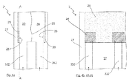
- a corresponding collector insulation 28 is assigned to each individual inlet region of each cell feed line 332.
- FIG. 5 is a schematic representation of a fifth embodiment of an inlet portion 301 of a reaction cell of an electrochemical energy converter 2 with two different line throttling 361 shown.
- both line chokes can also be designed as adjustable line chokes 362.
- an inlet area isolation is preferably provided in the inlet area, which distributes the stream over a larger area.
- FIGS. 8a and 8b The schematic exemplary compilation of the FIGS. 8a and 8b known cell frames 271 and 272 is along the section lines BB corresponding to the FIGS. 8a and 8b manufactured.
- Redox flow battery 2 electrochemical energy converter 21 positive collector 22 negative collector 23 ion-conducting membrane 24 electrical line 25 bipolar partition / bipolar plate 26 monopolar partition / collector plate 27 cell borders 271 Cell frame first half cell 272 Cell frame second half cell 28 collector insulation 3 electrolyte ducts 301 inlet area 302 outlet 31
- Storage tank positive electrolyte 32 Storage tank negative electrolyte 33 positive electrolyte 331
- Feed line positive electrolyte 332 Cell supply positive electrolyte 333
- Discharge line positive electrolyte 334 Cell leakage positive electrolyte 34 negative electrolyte 341
- Supply line negative electrolyte 342 Cell supply negative electrolyte 343 Discharge line negative electrolyte 344 Cell dissipation of negative electrolyte 35 cable insulation 361 line throttling 362 adjustable line throttling 37 Seal / O-ring 4 pump 5
- Charge controller / inverter / battery control 51 battery 6 Power source / consumer X Flow direction electrolyt
Landscapes
- Life Sciences & Earth Sciences (AREA)
- Engineering & Computer Science (AREA)
- Manufacturing & Machinery (AREA)
- Sustainable Development (AREA)
- Sustainable Energy (AREA)
- Chemical & Material Sciences (AREA)
- Chemical Kinetics & Catalysis (AREA)
- Electrochemistry (AREA)
- General Chemical & Material Sciences (AREA)
- Fuel Cell (AREA)
Applications Claiming Priority (1)
| Application Number | Priority Date | Filing Date | Title |
|---|---|---|---|
| DE102012006642A DE102012006642A1 (de) | 2012-04-03 | 2012-04-03 | Durchflussbatterie, elektrochemischer Energiewandler für eine Durchflussbatterie, Zellrahmen und Bipolarplatte sowie Kollektorplatte |
Publications (1)
| Publication Number | Publication Date |
|---|---|
| EP2648257A1 true EP2648257A1 (fr) | 2013-10-09 |
Family
ID=48045294
Family Applications (1)
| Application Number | Title | Priority Date | Filing Date |
|---|---|---|---|
| EP13162164.1A Withdrawn EP2648257A1 (fr) | 2012-04-03 | 2013-04-03 | Batterie à circulation, convertisseur d'énergie électrochimique pour une batterie à circulation, cadre d'élément, plaque bipolaire et plaque de collecteur |
Country Status (2)
| Country | Link |
|---|---|
| EP (1) | EP2648257A1 (fr) |
| DE (1) | DE102012006642A1 (fr) |
Cited By (3)
| Publication number | Priority date | Publication date | Assignee | Title |
|---|---|---|---|---|
| WO2015135771A1 (fr) * | 2014-03-12 | 2015-09-17 | Schmid Energy Systems Gmbh | Ensemble de cellules électrochimiques |
| DE102022105339A1 (de) | 2022-03-08 | 2023-09-14 | Schaeffler Technologies AG & Co. KG | Redox-Flow-Converter und Verfahren zur Herstellung eines Redox-Flow-Converters |
| DE102023118254A1 (de) | 2023-07-11 | 2025-01-16 | Schaeffler Technologies AG & Co. KG | Redox-Flow-Converter |
Citations (13)
| Publication number | Priority date | Publication date | Assignee | Title |
|---|---|---|---|---|
| DE914264C (de) | 1949-06-28 | 1954-06-28 | Dr Walther Kangro | Verfahren zur Speicherung von elektrischer Energie |
| DE3338724A1 (de) | 1983-10-25 | 1985-05-02 | Siemens AG, 1000 Berlin und 8000 München | Batterie aus redoxzellen |
| US4528250A (en) | 1983-09-19 | 1985-07-09 | Struthers Ralph C | Fuel cell catholyte regenerating apparatus |
| AU5556286A (en) | 1986-02-11 | 1987-08-13 | Pinnacle Vrb Limited | All vanadium redox battery |
| JPS6369151A (ja) * | 1986-09-09 | 1988-03-29 | Kawasaki Heavy Ind Ltd | レドツクス電池 |
| DE69600381T2 (de) | 1995-02-16 | 1998-10-29 | Kashima Kita Electric Power Co | Redox Batterie |
| DE69801341T2 (de) | 1998-01-28 | 2001-11-22 | Squirrel Holdings Ltd., George Town | Redox durchflussbatteriesystem und zellenstapel |
| DE69711493T2 (de) | 1996-06-19 | 2002-11-07 | Kashima-Kita Electric Power Corp., Ibaraki | Redox-Durchflussbatterie |
| WO2006111704A1 (fr) | 2005-04-16 | 2006-10-26 | Re-Fuel Technology Limited | Empilage de piles electrochimiques avec elements de chassis |
| AT502979A4 (de) | 2006-05-15 | 2007-06-15 | Funktionswerkstoffe Forschungs | Elektrochemischer strömungsmodul mit einer einrichtung zum unterdrücken eines elektrischen nebenschlussstromes |
| US20080081247A1 (en) * | 2001-06-12 | 2008-04-03 | Sumitomo Electric Industries, Ltd. | Cell frame for redox flow battery, and redox flow battery |
| US20110223450A1 (en) * | 2008-07-07 | 2011-09-15 | Enervault Corporation | Cascade Redox Flow Battery Systems |
| WO2011114094A1 (fr) | 2010-03-19 | 2011-09-22 | Renewable Energy Dynamics Technology Ltd | Empilement de cellules électrochimiques |
-
2012
- 2012-04-03 DE DE102012006642A patent/DE102012006642A1/de not_active Withdrawn
-
2013
- 2013-04-03 EP EP13162164.1A patent/EP2648257A1/fr not_active Withdrawn
Patent Citations (13)
| Publication number | Priority date | Publication date | Assignee | Title |
|---|---|---|---|---|
| DE914264C (de) | 1949-06-28 | 1954-06-28 | Dr Walther Kangro | Verfahren zur Speicherung von elektrischer Energie |
| US4528250A (en) | 1983-09-19 | 1985-07-09 | Struthers Ralph C | Fuel cell catholyte regenerating apparatus |
| DE3338724A1 (de) | 1983-10-25 | 1985-05-02 | Siemens AG, 1000 Berlin und 8000 München | Batterie aus redoxzellen |
| AU5556286A (en) | 1986-02-11 | 1987-08-13 | Pinnacle Vrb Limited | All vanadium redox battery |
| JPS6369151A (ja) * | 1986-09-09 | 1988-03-29 | Kawasaki Heavy Ind Ltd | レドツクス電池 |
| DE69600381T2 (de) | 1995-02-16 | 1998-10-29 | Kashima Kita Electric Power Co | Redox Batterie |
| DE69711493T2 (de) | 1996-06-19 | 2002-11-07 | Kashima-Kita Electric Power Corp., Ibaraki | Redox-Durchflussbatterie |
| DE69801341T2 (de) | 1998-01-28 | 2001-11-22 | Squirrel Holdings Ltd., George Town | Redox durchflussbatteriesystem und zellenstapel |
| US20080081247A1 (en) * | 2001-06-12 | 2008-04-03 | Sumitomo Electric Industries, Ltd. | Cell frame for redox flow battery, and redox flow battery |
| WO2006111704A1 (fr) | 2005-04-16 | 2006-10-26 | Re-Fuel Technology Limited | Empilage de piles electrochimiques avec elements de chassis |
| AT502979A4 (de) | 2006-05-15 | 2007-06-15 | Funktionswerkstoffe Forschungs | Elektrochemischer strömungsmodul mit einer einrichtung zum unterdrücken eines elektrischen nebenschlussstromes |
| US20110223450A1 (en) * | 2008-07-07 | 2011-09-15 | Enervault Corporation | Cascade Redox Flow Battery Systems |
| WO2011114094A1 (fr) | 2010-03-19 | 2011-09-22 | Renewable Energy Dynamics Technology Ltd | Empilement de cellules électrochimiques |
Cited By (5)
| Publication number | Priority date | Publication date | Assignee | Title |
|---|---|---|---|---|
| WO2015135771A1 (fr) * | 2014-03-12 | 2015-09-17 | Schmid Energy Systems Gmbh | Ensemble de cellules électrochimiques |
| DE102014103292A1 (de) | 2014-03-12 | 2015-09-17 | Schmid Energy Systems Gmbh | Verbund von elektrochemischen Zellen |
| DE102022105339A1 (de) | 2022-03-08 | 2023-09-14 | Schaeffler Technologies AG & Co. KG | Redox-Flow-Converter und Verfahren zur Herstellung eines Redox-Flow-Converters |
| DE102023118254A1 (de) | 2023-07-11 | 2025-01-16 | Schaeffler Technologies AG & Co. KG | Redox-Flow-Converter |
| EP4496046A1 (fr) | 2023-07-11 | 2025-01-22 | Schaeffler Technologies AG & Co. KG | Convertisseur de flux redox |
Also Published As
| Publication number | Publication date |
|---|---|
| DE102012006642A1 (de) | 2013-10-10 |
Similar Documents
| Publication | Publication Date | Title |
|---|---|---|
| DE69905949T2 (de) | Mehrschicht-verteileranordnung mit effizientem volumenausbau für elektrochemische brennstoffzellenstapel | |
| EP0876686B1 (fr) | Cellule electrochimique refroidie par liquide et munie de canaux de distribution | |
| EP2025029B1 (fr) | Système de refroidissement pour pile à combustible | |
| EP2795710B1 (fr) | Batterie à circulation d'oxydo-réduction avec ligne d'alimentation et/ou ligne d'évacuation externes | |
| DE102015225228A1 (de) | Bipolarplatte für eine Brennstoffzelle sowie Brennstoffzellenstapel mit einer solchen | |
| DE19539959C2 (de) | Brennstoffzellenanordnung | |
| DE102015215231A1 (de) | Bipolarplatte sowie Brennstoffzellensystem mit einer solchen | |
| DE112007000282T5 (de) | Brennstoffzelle | |
| WO2019141601A1 (fr) | Plaque bipolaire, pile à combustible et véhicule automobile | |
| EP3476000B1 (fr) | Dispositif de conversion d'énergie, en particulier pile à combustible ou électrolyseur | |
| WO2024083406A2 (fr) | Agencement d'éléments pour batterie à flux redox et batterie à flux redox | |
| DE102017218029B4 (de) | Brennstoffzelle | |
| DE102012006642A1 (de) | Durchflussbatterie, elektrochemischer Energiewandler für eine Durchflussbatterie, Zellrahmen und Bipolarplatte sowie Kollektorplatte | |
| EP1394877B1 (fr) | Element conçu sous forme de plaques pour piles à combustible | |
| DE102015200427A1 (de) | Brennstoffzellensystem mit mehreren Brennstoffzellenstapeln | |
| EP3915164B1 (fr) | Module de distribution pour relier les éléments d'un empilement d'éléments et l'empilement d'éléments à un module de distribution | |
| WO2017085030A1 (fr) | Empilement de piles à combustible, comprenant des plaques bipolaires, et système de piles à combustible | |
| DE10229820B4 (de) | Gasverteilungsvorrichtung für eine elektrochemische Elektrode und Verfahren zur Reaktionsgasbeaufschlagung einer elektrochemischen Elektrode | |
| DE102021106068B3 (de) | Brennstoffzelle und Verfahren zum Herstellen von Brennstoffzellen | |
| AT513558B1 (de) | Wiederaufladbare Batteriezelle und Batteriemodul | |
| DE102023100399B4 (de) | Zellrahmen, elektrochemische zelle und elektrochemischer flussreaktor | |
| EP2930776B1 (fr) | Cellule galvanique et cellule à flux redox | |
| EP4627649A1 (fr) | Dispositif de régulation de température et procédé de chauffage de cylindres de travail | |
| WO2015135771A1 (fr) | Ensemble de cellules électrochimiques | |
| DE10262014B4 (de) | Gasverteilungsvorrichtung für eine elektrochemische Elektrode, Elektrochemische Elektrodenanordnung, Elektroden-Membran-Einheit und Verfahren zur Reaktionsgasbeaufschlagung einer elektrochemischen Elektrode |
Legal Events
| Date | Code | Title | Description |
|---|---|---|---|
| PUAI | Public reference made under article 153(3) epc to a published international application that has entered the european phase |
Free format text: ORIGINAL CODE: 0009012 |
|
| AK | Designated contracting states |
Kind code of ref document: A1 Designated state(s): AL AT BE BG CH CY CZ DE DK EE ES FI FR GB GR HR HU IE IS IT LI LT LU LV MC MK MT NL NO PL PT RO RS SE SI SK SM TR |
|
| AX | Request for extension of the european patent |
Extension state: BA ME |
|
| 17P | Request for examination filed |
Effective date: 20140409 |
|
| RBV | Designated contracting states (corrected) |
Designated state(s): AL AT BE BG CH CY CZ DE DK EE ES FI FR GB GR HR HU IE IS IT LI LT LU LV MC MK MT NL NO PL PT RO RS SE SI SK SM TR |
|
| RAP1 | Party data changed (applicant data changed or rights of an application transferred) |
Owner name: BOZANKAYA BC&C GMBH |
|
| R17P | Request for examination filed (corrected) |
Effective date: 20140409 |
|
| 17Q | First examination report despatched |
Effective date: 20180326 |
|
| STAA | Information on the status of an ep patent application or granted ep patent |
Free format text: STATUS: THE APPLICATION IS DEEMED TO BE WITHDRAWN |
|
| 18D | Application deemed to be withdrawn |
Effective date: 20181006 |