EP2648401B1 - Terminal mobile, procédé et programme de traitement d'image - Google Patents
Terminal mobile, procédé et programme de traitement d'image Download PDFInfo
- Publication number
- EP2648401B1 EP2648401B1 EP11845376.0A EP11845376A EP2648401B1 EP 2648401 B1 EP2648401 B1 EP 2648401B1 EP 11845376 A EP11845376 A EP 11845376A EP 2648401 B1 EP2648401 B1 EP 2648401B1
- Authority
- EP
- European Patent Office
- Prior art keywords
- images
- lens
- image
- view
- controller
- Prior art date
- Legal status (The legal status is an assumption and is not a legal conclusion. Google has not performed a legal analysis and makes no representation as to the accuracy of the status listed.)
- Not-in-force
Links
Images


Classifications
-
- G—PHYSICS
- G02—OPTICS
- G02B—OPTICAL ELEMENTS, SYSTEMS OR APPARATUS
- G02B13/00—Optical objectives specially designed for the purposes specified below
- G02B13/001—Miniaturised objectives for electronic devices, e.g. portable telephones, webcams, PDAs, small digital cameras
- G02B13/009—Miniaturised objectives for electronic devices, e.g. portable telephones, webcams, PDAs, small digital cameras having zoom function
-
- G—PHYSICS
- G03—PHOTOGRAPHY; CINEMATOGRAPHY; ANALOGOUS TECHNIQUES USING WAVES OTHER THAN OPTICAL WAVES; ELECTROGRAPHY; HOLOGRAPHY
- G03B—APPARATUS OR ARRANGEMENTS FOR TAKING PHOTOGRAPHS OR FOR PROJECTING OR VIEWING THEM; APPARATUS OR ARRANGEMENTS EMPLOYING ANALOGOUS TECHNIQUES USING WAVES OTHER THAN OPTICAL WAVES; ACCESSORIES THEREFOR
- G03B13/00—Viewfinders; Focusing aids for cameras; Means for focusing for cameras; Autofocus systems for cameras
- G03B13/32—Means for focusing
- G03B13/34—Power focusing
- G03B13/36—Autofocus systems
-
- H—ELECTRICITY
- H04—ELECTRIC COMMUNICATION TECHNIQUE
- H04N—PICTORIAL COMMUNICATION, e.g. TELEVISION
- H04N23/00—Cameras or camera modules comprising electronic image sensors; Control thereof
-
- H—ELECTRICITY
- H04—ELECTRIC COMMUNICATION TECHNIQUE
- H04N—PICTORIAL COMMUNICATION, e.g. TELEVISION
- H04N23/00—Cameras or camera modules comprising electronic image sensors; Control thereof
- H04N23/60—Control of cameras or camera modules
- H04N23/67—Focus control based on electronic image sensor signals
- H04N23/673—Focus control based on electronic image sensor signals based on contrast or high frequency components of image signals, e.g. hill climbing method
-
- H—ELECTRICITY
- H04—ELECTRIC COMMUNICATION TECHNIQUE
- H04N—PICTORIAL COMMUNICATION, e.g. TELEVISION
- H04N23/00—Cameras or camera modules comprising electronic image sensors; Control thereof
- H04N23/60—Control of cameras or camera modules
- H04N23/69—Control of means for changing angle of the field of view, e.g. optical zoom objectives or electronic zooming
-
- H—ELECTRICITY
- H04—ELECTRIC COMMUNICATION TECHNIQUE
- H04N—PICTORIAL COMMUNICATION, e.g. TELEVISION
- H04N5/00—Details of television systems
- H04N5/222—Studio circuitry; Studio devices; Studio equipment
- H04N5/262—Studio circuits, e.g. for mixing, switching-over, change of character of image, other special effects ; Cameras specially adapted for the electronic generation of special effects
- H04N5/2628—Alteration of picture size, shape, position or orientation, e.g. zooming, rotation, rolling, perspective, translation
-
- H—ELECTRICITY
- H04—ELECTRIC COMMUNICATION TECHNIQUE
- H04N—PICTORIAL COMMUNICATION, e.g. TELEVISION
- H04N23/00—Cameras or camera modules comprising electronic image sensors; Control thereof
- H04N23/60—Control of cameras or camera modules
- H04N23/63—Control of cameras or camera modules by using electronic viewfinders
Definitions
- the present invention relates to a camera-equipped mobile terminal, a method of image processing, and a program for causing the mobile terminal to implement the image processing.
- Cameras are known that include a function called continuous autofocus (hereinafter denoted as AF-C), by which a subject as a distinct point is continuously kept in focus.
- AF-C continuous autofocus
- a digital camera is provided with a display such as a liquid crystal panel.
- AF-C continuous autofocus
- a user can see images output on a display to confirm that the focus remains fixed on a subject even if the subject changes or moves.
- AF-C may be roughly divided into two modes; a minute movement mode and an in-focus position search mode.
- minute movement mode images are captured while a lens is minutely moved back and forth relative to the current position in an optical axis direction.
- in-focus position search mode the lens is moved to an in-focus position if the analysis of the images captured by the minutely moved lens suggests an out-of-focus state.
- the camera minutely moves the lens in order to determine whether it is necessary to search for the in-focus position, even when substantially no changes occur in the position of a subject with respect to the direction of the optical axis of the lens.
- the minute movements then alter the optical path, causing variations in the angle of view of images output on the display.
- a subject that wobbles back and forth is displayed on the display screen, so that the subject appears to vary in size. This creates discomfort for the user who is viewing.
- Patent document 1 discloses an apparatus for controlling the driving of lenses, including lenses and a position detector that detects the positions of the lenses. Each of the lenses may be independently controlled to eliminate variations in the angle of view.
- Patent document 2 discloses an imaging apparatus, including lenses and a position detector that detects the positions of the lenses. Each of the lenses may be independently controlled to restrain the variations in the angle of view of output images.
- the apparatus for controlling the driving of lenses disclosed in patent document 1 is directed to TV broadcast cameras and therefore can be applied to cameras designed mainly for shooting images.
- the techniques disclosed in patent documents 1 and 2 require a configuration in which a controller independently controls each of the lenses and in which a position detector detects the position of each lens.
- an exemplary object of the invention is to provide a mobile terminal, a method of image processing, and a program for causing the mobile terminal to implement the image processing, such that variations in the angle of view of displayed images are prevented while AF-C is being performed.
- a mobile terminal according to an exemplary aspect of the invention is set out in claim 1.
- a method of image processing according to the present invention is set out in claim 2.
- a configuration of a mobile terminal in an exemplary embodiment will be described.
- detailed description of components of portions relevant to the present invention will be given, while detailed description of components relevant to mobile-terminal functions will be omitted.
- Fig. 1 is a block diagram showing an exemplary configuration of the mobile terminal in the exemplary embodiment.
- Fig. 2 is a block diagram showing an exemplary configuration of a camera unit shown in Fig. 1 .
- the mobile terminal in the exemplary embodiment comprises camera unit 11, image memory 12 that stores images output from camera unit 11, display 14 that outputs images stored in image memory 12, and controller 16 that controls these components.
- Controller 16 comprises angle-of-view correction unit 13 that corrects the angles of view of images captured by camera unit 11 and focus assessment unit 15 that determines whether focus is achieved based on images captured by camera unit 11.
- Controller 16 is provided with a CPU (Central Processing Unit) (not shown) that performs processing according to a program, and memory (not shown) for storing the program.
- a threshold for determining whether focus is achieved is written in advance.
- the CPU executes the program to implement angle-of-view correction unit 13 and focus assessment unit 15 as virtual units in the mobile terminal.
- camera unit 11 comprises lens 111, driver 112 that moves lens 111 in the optical axis direction, image sensor 113 that converts images projected through lens 111 into electric signals, and A/D converter 114 that converts the analog electric signals output from image sensor 113 into digital signals.
- Fig. 2 shows one convex lens 111, one or more lenses 111 may be employed.
- the type of lens 111 is not limited to a convex type.
- Image sensor 113 is, for example, a CCD (Charge Coupled Device) or CMOS (Complementary Metal Oxide Semiconductor) image sensor.
- A/D converter 114 converts image data received from image sensor 113 into digital signals and sends the digital signals to controller 16.
- Image memory 12 may be volatile memory such as DRAM (Dynamic Random Access Memory) or SRAM (Static RAM), or nonvolatile memory such as flash memory.
- Image memory 12 stores data on images captured by camera unit 11, and data on images corrected by controller 16.
- Display 14 outputs images received from controller 16.
- focus assessment unit 15 in controller 16 Upon input of an instruction to perform AF-C, focus assessment unit 15 in controller 16 causes camera unit 11 to execute a minute movement mode at regular time intervals. Specifically, focus assessment unit 15 sends control signals driver 112 instructing it to move lens 111 back and forth in the optical axis direction, and stores in image memory 12 pieces of image data received from A/D converter 114.
- Focus assessment unit 15 also determines, for images of the pieces of image data stored in image memory 12, whether the amount of change in contrast exceeds the above-mentioned threshold. If the amount of change in contrast exceeds the threshold, focus assessment unit 15 determines that lens 111 is not at an in-focus position. If the amount of change in contrast does not exceed the threshold, focus assessment unit 15 determines that lens 111 is at the in-focus position. If focus assessment unit 15 determines that lens 111 is not at the in-focus position, focus assessment unit 15 determines, as a new in-focus position, the position of lens 111 at which the image contrast is the maximum based on the contrasts of the images, and executes an in-focus position search mode. Specifically, focus assessment unit 15 sends a control signal to driver 112 instructing it to move lens 111 to the determined in-focus position.
- the portion of each image that is to be used for the comparison of the contrast is written in advance in the program.
- the portion at which the contrast is to be compared may be a predetermined range around the center of each image, or may be an area containing a human face detected by instantaneous analysis of each image.
- the value of the "contrast" to be compared may not be the value of the contrast itself detected for every pixel of image sensor 113 shown in Fig. 2 . Rather, the value may be the sum of the differences between the contrast values of adjacent pixels in an area specified as an area to be compared. This is based on a characteristic in which the more an image is in focus, the greater are the differences between the contrast values of adjacent pixels.
- focus assessment unit 15 may instruct driver 112 to move lens 111 to the in-focus position through various approaches, two approaches will be described here.
- the first one of the two approaches is as follows.
- a table is stored in advance in memory (not shown) in controller 16.
- the table represents the relationship between the number of pulses serving as a signal instructing driver 112 to move lens 111 through a predetermined distance and the moving distance of lens 111.
- Focus assessment unit 15 identifies the current position of lens 111 from information on the number of pulses sent to driver 112 at the last activation of driver 112. Focus assessment unit 15 then calculates the difference between the current position and the in-focus position and refers to the table to determine the number of pulses corresponding to the difference. Focus assessment unit 15 sends the determined number of pulses to driver 112.
- focus assessment unit 15 receives from driver 112 position signals indicating the positions of lens 111. Based on the position signals and the contrasts of captured images, focus assessment unit 15 generates a graph representing changes in contrast for the position signals. The graph is stored in memory (not shown) in controller 16. Focus assessment unit 15 refers to the graph to determine a position signal corresponding to the maximum contrast, and sends a control signal to driver 112 containing the position signal and an instruction to move lens 111.
- angle-of-view correction unit 13 takes any one of the image from among the plurality of image data as a reference and corrects the other images so that their angles of view match the angle of view of the one image.
- Angle-of-view correction unit 13 sends the one reference image and the other corrected images to display 14.
- the one image referenced in the angle-of-view correction will hereinafter be referred to as a base image.
- An exemplary method of image correction by angle-of-view correction unit 13 will be described in detail later.
- each of angle-of-view correction unit 13 and focus assessment unit 15, or part of functions of these units may be implemented with a dedicated integrated circuit such as a gate array.
- FIG. 3 is a flowchart showing the operation of the mobile terminal in the exemplary embodiment.
- the mobile terminal When the user directs camera unit 11 of the mobile terminal to a subject and operates the mobile terminal to input thereto an instruction to prepare for shooting, the mobile terminal activates camera unit 11. In order to determine whether the subject is in focus, the mobile terminal executes the minute movement mode, in which images are captured while lens 111 is moved back and forth in the optical axis direction. The mobile terminal corrects the angles of view of the images captured in the minute movement mode and outputs the corrected images to display 14 (step 201).
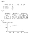
- Figs. 4A and 4B are diagrams for describing the relationship between images obtained in the minute movement mode and lens positions at the times of capturing.
- Fig. 4A is a graph showing the lens positions along the optical axis direction, while Fig. 4B shows the images captured with respective lens positions X1 to X3.
- JP indicates the in-focus position.
- the angle of view of the image captured with lens position X1 is narrower than the angle of view of the image captured with lens position X2, which is closer to the INF side relative to the in-focus position.
- the angle of view of the image captured with lens position X1 is wider than the angle of view of the image captured with lens position X3, which is closer to the macro side relative to the in-focus position.
- Fig. 5 shows an exemplary graph illustrating the relationship between the angle of view and the lens position. In the graph shown in Fig. 5 , the ordinate indicates the width of the angle of view while the abscissa indicates the lens position. It can be seen from Fig. 5 that the closer the lens position to the INF side, the wider the angle of view.
- Fig. 6 is a diagram for describing a method of angle-of-view correction for the three images shown in Fig. 4B .
- Fig. 7 is a flowchart showing a procedure of the method of angle-of-view correction in the process in step 201 shown in Fig. 3 .
- the mobile terminal captures the subject while moving lens 111 back and forth in the optical axis direction in the minute movement mode, thereby obtaining three images with different angles of view (step 211).
- the mobile terminal stores the three images in image memory 12 (step 212) and designates, as the base image, an image with the narrowest angle of view among the three images. Accordingly, among the three images shown in Fig. 4B , the image captured with lens position X3 (image A shown in Fig. 6 ) is the base image.
- Angle-of-view correction unit 13 in the mobile terminal corrects the other images so that their angles of view match the angle of view of image A (step 213). Specifically, angle-of view correction unit 13 clips out an area matching the angle of view of image A from the image captured with lens position X1 and sets, as image B, the clipped-out area enlarged to the size of image A. In Fig. 6 , an area surrounded by a dot-dash line is the clipped-out area. Angle-of-view correction unit 13 also clips out an area matching the angle of view of image A from the image captured with lens position X2 and sets, as image C, the clipped-out area enlarged to the size of image A.
- the mobile terminal designates the image with the narrowest angle of view as the base image.
- This provides the following advantage: in the process in step 213 in which an area in each of the images captured with lens positions X1 and X2 is clipped out and aligned with the size of image A, the clipped-out area only needs to be enlarged to the size of image A.
- angle-of-view correction unit 13 sequentially sends images A, B, and C to display 14 to cause display 14 to sequentially output these images (step 214).
- the image processing described with reference to Figs. 3 and 7 is performed at every minute movement mode executed at regular time intervals in which lens 111 is moved back and forth in the optical axis direction. Since this allows any of images continuously displayed on display 14 to have the same angle of view, the subject never appears to vary in size, creating no discomfort for the user.
- step 202 shown in Fig. 3 in order to determine whether or not focus is achieved, the mobile terminal refers to the three pieces of image data stored in image memory 12 to determine whether the amount of change in the contrast of the three images exceeds the threshold (step 202). If it is determined in step 202 that the amount of change in contrast exceeds the threshold, the mobile terminal determines that lens 111 is not at the in-focus position. The mobile terminal then determines, as a new in-focus position, a lens position at which the contrast is the maximum from the relationship between the image contrast and the lens position based on the contrasts of the three images, and executes the in-focus position search mode (step 203). After the process in step 203, the mobile terminal returns to step 201.
- step 202 If it is determined in step 202 that the amount of change in the contrast does not exceed the threshold, the mobile terminal determines that lens 111 is at the in-focus position and returns to step 201.
- image A is designated as the base image.
- the base image may be the image captured with lens position X1 shown in Fig. 4B . This is because, while AF-C executes the minute movement mode at regular time intervals, the position of lens 111 is likely to be at the in-focus position before the start of the next minute movement mode.
- the mobile terminal in the exemplary embodiment performs AF-C
- the mobile terminal obtains images while moving the lens, extracts the differences of the images with respect to variations in angles of view of the images, and corrects the images so that their angles of view match each other.
- This allows restraining the variations in angle of view due to the minute movements of the lens.
- the mobile terminal therefore does not need to independently control each of the multiple lenses, thus meeting the demand for miniaturization of cameras for mobile devices such as mobile phones. Since variations in the angle of view of the images output on the display during AF-C are prevented, no discomfort is created for the user viewing the display.
- an image on the macro-end side may be taken as the base image to process the other images so that their angles of view match the angle of view of the base image.
- variations in the angle of view due to the lens movements from the macro end to the ⁇ end may be corrected.
- the method of image processing in the exemplary embodiment is applicable not only to correcting variations in the angle of view due to the minute movements in AF-C, but also to preventing image wobbles that may occur in usual AF.
- a technique similar to the method of image processing in the exemplary embodiment is a camera-shake correction technique for moving images.
- Camera shake which means that a user's hand holding a camera is not fixed but shaky, causes the problem of frame- by-frame misalignment of the angles of view of images of a subject captured while camera shake occurs.
- the camera-shake correction technique involves: setting the margin of a predetermined width along the periphery within each of all captured images; clipping out an area with the same angle of view excluding the margin from each of the continuous frames; and outputting or recording the clipped-out areas.
- the camera-shake correction technique only clips out the same area from each frame and does not enlarge the images. Therefore, variations in the angle of view due to the lens movements in the optical axis direction cannot be corrected.
- the method of image processing in the exemplary embodiment may be regarded as a method involving extraction of a distinct point, such as the method of detecting differences by the camera-shake correction technique.
- the exemplary embodiment only enlarges or reduces the images by the amount of variations in the angle of view corresponding to the differences from the base image, and the distinct point is common among the frames. Therefore, the exemplary embodiment can be more easily implemented than the camera-shake correction technique.
- the present invention is applicable to a mobile terminal with a camera including an image sensor and with an image processing function, such as a mobile phone, a PHS (Personal Handyphone System), or a PDA (Personal Digital Assistant).
- the program of the present invention may be recorded on a computer-readable recording medium.
- focus assessment unit 15 is illustrated in the functional block diagram shown in Fig. 1 in order to detail the method of image processing in the exemplary embodiment.
- the mobile terminal may only need to include camera unit 11, image memory 12, angle-of-view correction unit 13, and display 14, among the components shown in Fig. 1 .
- An exemplary advantage of the present invention is the ability to prevent variations in the angle of view of images output on the display without requiring complicated lens control for the minute movements of the lens as in AF-C.
Landscapes
- Engineering & Computer Science (AREA)
- Multimedia (AREA)
- Signal Processing (AREA)
- Physics & Mathematics (AREA)
- General Physics & Mathematics (AREA)
- Optics & Photonics (AREA)
- Studio Devices (AREA)
- Automatic Focus Adjustment (AREA)
- Focusing (AREA)
Claims (3)
- Terminal mobile comprenant :(a) une unité de caméra (11) exécutant un mode de mouvement infime, dans lequel un sujet est capturé pendant qu'un objectif (111) est reculé et avancé dans une direction d'axe optique, et fournissant en sortie une pluralité d'images ayant différents angles de champ ;(b) une unité de stockage (12) stockant la pluralité d'images fournies en sortie par l'unité de caméra (11) ;(c) une unité de correction d'angle de champ (13) prenant une image quelconque de la pluralité d'images stockées dans l'unité de stockage comme image de base et corrigeant les autres images de la pluralité d'images de sorte que les angles de champ des autres images correspondent à l'angle de champ de l'image de base ;(d) un afficheur (14) fournissant en sortie l'image de base et les autres images corrigées par l'unité de correction d'angle de champ ; et(e) une unité d'évaluation de focalisation (15) déterminant si l'objectif (111) est dans une position de netteté ou non en se basant sur le fait qu'une quantité de changement de contraste de la pluralité d'images stockées dans l'unité de stockage d'images dépasse un seuil prédéterminé ou non, dans lequel(f) si la quantité de changement de contraste de la pluralité d'images dépasse le seuil, l'unité d'évaluation de focalisation (15) détermine, comme nouvelle position de netteté, une position de l'objectif au niveau de laquelle le contraste maximal d'image est obtenu en se basant sur des contrastes de la pluralité d'images, et(g) l'unité de correction d'angle de champ (13) prend une image, qui correspond à la nouvelle position de netteté de l'objectif, comme image de base de la pluralité d'images qui seront obtenues par le mouvement de mouvement infime suivant.
- Procédé de traitement d'image pour une unité de commande dans un terminal mobile, le terminal mobile comprenant une unité de caméra (11) dotée d'un objectif (111), d'une unité de stockage (12), d'un afficheur (14) et de l'unité de commande (16), le procédé comprenant :le fait que l'unité de commande (16) amène l'unité de caméra (11) à exécuter un mode de mouvement infime, dans lequel un sujet est capturé pendant que l'objectif est reculé et avancé dans une direction d'axe optique et à fournir en sortie une pluralité d'images ayant des angles de champ différents ;le stockage par l'unité de commande (16) de la pluralité d'images fournies en sortie par l'unité de caméra dans l'unité de stockage ;la prise par l'unité de commande (16) d'une image quelconque de la pluralité d'images stockées dans l'unité de stockage comme image de base et la correction des autres images de la pluralité d'images de sorte que les angles de champ des autres images correspondent à l'angle de champ de l'image de base ; etle fait que l'unité de commande (16) amène l'afficheur à fournir en sortie l'image de base et les autres images corrigées ; etla détermination par l'unité de commande (16) du fait que l'objectif (111) est ou non en une position de netteté en se basant sur le fait qu'une quantité de changement de contraste de la pluralité d'images stockées dans l'unité de stockage dépasse un seuil prédéterminé ou non ; dans lequels'il est déterminé que la quantité de changement de contraste de la pluralité d'images dépasse le seuil, la détermination par l'unité de commande (16), comme nouvelle position de netteté, d'une position de l'objectif au niveau de laquelle le contraste maximal d'image est obtenu en se basant sur des contrastes de la pluralité d'images, etla prise par l'unité de commande (16) d'une image, qui correspond à la nouvelle position de netteté de l'objectif, comme image de base de la pluralité d'images qui seront obtenues par le mode de mouvement infime suivant.
- Support d'enregistrement lisible par ordinateur dans lequel est enregistré un programme devant être exécuté par une unité de commande dans un terminal mobile, le terminal mobile comprenant une unité de caméra (11) dotée d'un objectif (111), d'une unité de stockage (12), d'un afficheur (14) et de l'unité de commande (16), dans lequel le programme amène l'unité de commande à réaliser un traitement comprenant :le fait d'amener l'unité de caméra à exécuter un mode de mouvement infime, dans lequel un sujet est capturé pendant que l'objectif est reculé et avancé dans une direction d'axe optique et à fournir en sortie une pluralité d'images ayant différents angles de champ ;le stockage de la pluralité d'images fournies en sortie par l'unité de caméra (11) dans l'unité de stockage (12) ;la prise d'une image quelconque de la pluralité d'images stockées dans l'unité de stockage comme une image de base et la correction des autres images de la pluralité d'images de sorte que les angles de champ des autres images correspondent à l'angle de champ de l'image de base ;le fait d'amener l'afficheur (14) à fournir en sortie l'image de base et les autres images corrigées ; etla détermination du fait que l'objectif est dans une position de netteté ou non en se basant sur le fait qu'une quantité de changement de contraste de la pluralité d'images stockées dans l'unité de stockage dépasse un seuil prédéterminé ou non, dans lequels'il est déterminé que la quantité de changement de contraste de la pluralité d'images dépasse le seuil, la détermination, comme nouvelle position de netteté, d'une position de l'objectif au niveau de laquelle le contraste maximal d'image est obtenu en se basant sur des contrastes de la pluralité d'images, etla prise d'une image, qui correspond à la nouvelle position de netteté de l'objectif, comme l'image de base de la pluralité d'images qui seront obtenues par le mode de mouvement infime suivant.
Applications Claiming Priority (2)
| Application Number | Priority Date | Filing Date | Title |
|---|---|---|---|
| JP2010268240 | 2010-12-01 | ||
| PCT/JP2011/077018 WO2012073779A1 (fr) | 2010-12-01 | 2011-11-24 | Terminal mobile, procédé et programme de traitement d'image |
Publications (3)
| Publication Number | Publication Date |
|---|---|
| EP2648401A1 EP2648401A1 (fr) | 2013-10-09 |
| EP2648401A4 EP2648401A4 (fr) | 2014-04-23 |
| EP2648401B1 true EP2648401B1 (fr) | 2015-08-26 |
Family
ID=46171721
Family Applications (1)
| Application Number | Title | Priority Date | Filing Date |
|---|---|---|---|
| EP11845376.0A Not-in-force EP2648401B1 (fr) | 2010-12-01 | 2011-11-24 | Terminal mobile, procédé et programme de traitement d'image |
Country Status (5)
| Country | Link |
|---|---|
| US (1) | US9041853B2 (fr) |
| EP (1) | EP2648401B1 (fr) |
| JP (1) | JPWO2012073779A1 (fr) |
| CN (1) | CN103222258B (fr) |
| WO (1) | WO2012073779A1 (fr) |
Families Citing this family (11)
| Publication number | Priority date | Publication date | Assignee | Title |
|---|---|---|---|---|
| JP6124655B2 (ja) * | 2013-04-05 | 2017-05-10 | オリンパス株式会社 | 撮像装置、撮像装置の制御方法及びプログラム |
| CN104243832A (zh) * | 2014-09-30 | 2014-12-24 | 北京金山安全软件有限公司 | 通过移动终端进行拍摄的方法、装置及移动终端 |
| JP2016086249A (ja) * | 2014-10-23 | 2016-05-19 | カシオ計算機株式会社 | 表示装置、表示制御方法及び表示制御プログラム |
| JP2017062598A (ja) * | 2015-09-24 | 2017-03-30 | ソニー株式会社 | 情報処理装置、情報処理方法、およびプログラム |
| US9992423B2 (en) * | 2015-10-14 | 2018-06-05 | Qualcomm Incorporated | Constant field of view for image capture |
| CN107155018A (zh) * | 2016-03-04 | 2017-09-12 | 阔展科技(深圳)有限公司 | 智能分析摄像机 |
| CN112312018B (zh) * | 2016-04-15 | 2022-05-17 | 深圳市大疆创新科技有限公司 | 使用自适应步长的对比度检测自动聚焦 |
| WO2018116824A1 (fr) * | 2016-12-19 | 2018-06-28 | ソニー株式会社 | Dispositif de commande, procédé de commande et programme |
| WO2018168214A1 (fr) * | 2017-03-14 | 2018-09-20 | 富士フイルム株式会社 | Dispositif d'imagerie, procédé de traitement du signal pour un dispositif d'imagerie, et programme de traitement du signal pour un dispositif d'imagerie |
| CN116762355A (zh) * | 2021-03-31 | 2023-09-15 | 深圳市大疆创新科技有限公司 | 视频拍摄方法、装置及系统 |
| US20250260897A1 (en) * | 2022-06-03 | 2025-08-14 | Sony Group Corporation | Information processing device, information processing method, and program |
Family Cites Families (45)
| Publication number | Priority date | Publication date | Assignee | Title |
|---|---|---|---|---|
| EP0441380B1 (fr) * | 1990-02-08 | 1996-09-11 | Canon Kabushiki Kaisha | Dispositif de prise de vue |
| JP3376241B2 (ja) | 1997-04-04 | 2003-02-10 | キヤノン株式会社 | ズームレンズのレンズ駆動制御装置 |
| JP3925751B2 (ja) | 1997-06-30 | 2007-06-06 | フジノン株式会社 | 撮影レンズの画角補正装置 |
| JPH11281873A (ja) * | 1998-03-31 | 1999-10-15 | Fuji Photo Optical Co Ltd | カメラのレンズ操作装置 |
| JP4217344B2 (ja) * | 1999-06-09 | 2009-01-28 | キヤノン株式会社 | ズームレンズ、ズームレンズシステムおよびカメラシステム |
| JP3937678B2 (ja) * | 2000-03-23 | 2007-06-27 | コニカミノルタホールディングス株式会社 | 電子スチルカメラ |
| JP2001281529A (ja) * | 2000-03-29 | 2001-10-10 | Minolta Co Ltd | デジタルカメラ |
| JP3624859B2 (ja) * | 2001-06-19 | 2005-03-02 | カシオ計算機株式会社 | 撮像装置、ソフトフォーカス画像撮影方法 |
| JP4198449B2 (ja) * | 2002-02-22 | 2008-12-17 | 富士フイルム株式会社 | デジタルカメラ |
| JP3680827B2 (ja) * | 2002-08-27 | 2005-08-10 | コニカミノルタフォトイメージング株式会社 | デジタルカメラ |
| US7295232B2 (en) * | 2003-01-15 | 2007-11-13 | Canon Kabushiki Kaisha | Camera and program |
| JP2004357202A (ja) * | 2003-05-30 | 2004-12-16 | Canon Inc | 撮影装置 |
| JP4164424B2 (ja) * | 2003-08-29 | 2008-10-15 | キヤノン株式会社 | 撮像装置及び方法 |
| JP2006129211A (ja) | 2004-10-29 | 2006-05-18 | Olympus Corp | 撮像装置 |
| JP4379728B2 (ja) * | 2005-01-31 | 2009-12-09 | カシオ計算機株式会社 | 撮像装置及びそのプログラム |
| JP2006258944A (ja) * | 2005-03-15 | 2006-09-28 | Fujinon Corp | オートフォーカスシステム |
| JP5013705B2 (ja) * | 2005-11-21 | 2012-08-29 | 三星電子株式会社 | 撮像装置,画面表示方法,焦点調整方法,露出調整方法,およびコンピュータプログラム |
| JP2007199195A (ja) | 2006-01-24 | 2007-08-09 | Fujinon Corp | レンズ制御装置 |
| JP4333685B2 (ja) * | 2006-03-29 | 2009-09-16 | セイコーエプソン株式会社 | カメラ、画像表示方法及びそのプログラム |
| JP4262263B2 (ja) * | 2006-06-07 | 2009-05-13 | キヤノン株式会社 | 撮像装置及びその制御方法 |
| JP2008042404A (ja) | 2006-08-03 | 2008-02-21 | Olympus Imaging Corp | デジタルカメラ |
| TWI309329B (en) * | 2006-10-03 | 2009-05-01 | Novatek Microelectronics Corp | Focus system and method for camera |
| JP5016909B2 (ja) * | 2006-12-15 | 2012-09-05 | キヤノン株式会社 | 撮像装置 |
| JP5013852B2 (ja) * | 2006-12-26 | 2012-08-29 | 三洋電機株式会社 | 画角補正装置及び方法並びに撮像装置 |
| US7639935B2 (en) * | 2007-03-28 | 2009-12-29 | Sony Ericsson Mobile Communications Ab | Zoom control |
| JP4582423B2 (ja) * | 2007-04-20 | 2010-11-17 | 富士フイルム株式会社 | 撮像装置、画像処理装置、撮像方法、及び画像処理方法 |
| US20090009651A1 (en) * | 2007-07-04 | 2009-01-08 | Sanyo Electric Co., Ltd. | Imaging Apparatus And Automatic Focus Control Method |
| JP4544282B2 (ja) * | 2007-09-14 | 2010-09-15 | ソニー株式会社 | データ処理装置、およびデータ処理方法、並びにプログラム |
| JP4974912B2 (ja) * | 2008-01-22 | 2012-07-11 | キヤノン株式会社 | 撮像装置 |
| JP4843002B2 (ja) * | 2008-01-25 | 2011-12-21 | ソニー株式会社 | 撮像装置、および撮像装置制御方法、並びにコンピュータ・プログラム |
| US8300136B2 (en) * | 2008-06-26 | 2012-10-30 | Canon Kabushiki Kaisha | Imaging apparatus for detecting a face image and imaging method |
| JP5223644B2 (ja) * | 2008-12-15 | 2013-06-26 | パナソニック株式会社 | 撮像装置 |
| JP2010147715A (ja) * | 2008-12-17 | 2010-07-01 | Hoya Corp | 撮像装置 |
| JP4780205B2 (ja) | 2009-02-23 | 2011-09-28 | カシオ計算機株式会社 | 撮像装置、画角調節方法、及び、プログラム |
| JP5206494B2 (ja) * | 2009-02-27 | 2013-06-12 | 株式会社リコー | 撮像装置、画像表示装置と、撮像方法及び画像表示方法並びに合焦領域枠の位置補正方法 |
| JP5299912B2 (ja) * | 2009-04-20 | 2013-09-25 | 株式会社ザクティ | 撮像装置及び画像ファイルのデータ構造 |
| JP4784678B2 (ja) * | 2009-04-22 | 2011-10-05 | カシオ計算機株式会社 | 撮像装置、撮像方法及びプログラム |
| JP5249125B2 (ja) | 2009-05-14 | 2013-07-31 | キヤノン株式会社 | 巻取り装置 |
| US8743269B2 (en) * | 2009-06-15 | 2014-06-03 | Olympus Imaging Corp. | Photographing device, photographing method, and playback method |
| JP5120356B2 (ja) * | 2009-10-13 | 2013-01-16 | 株式会社ニコン | 撮像装置 |
| JP2011135490A (ja) * | 2009-12-25 | 2011-07-07 | Seiko Epson Corp | デジタルカメラおよびその製造方法 |
| JP2011210139A (ja) * | 2010-03-30 | 2011-10-20 | Sony Corp | 画像処理装置および方法、並びにプログラム |
| JP5810505B2 (ja) * | 2010-11-01 | 2015-11-11 | 株式会社ソシオネクスト | 撮像制御装置、撮像装置、及び撮像制御方法 |
| US8526805B2 (en) * | 2010-12-20 | 2013-09-03 | Canon Kabushiki Kaisha | Lens apparatus and camera system including the same |
| EP2574065B1 (fr) * | 2011-01-26 | 2016-09-07 | FUJIFILM Corporation | Dispositif de traitement d'image, dispositif de capture d'image, dispositif de reproduction et procédé de traitement d'image |
-
2011
- 2011-11-24 WO PCT/JP2011/077018 patent/WO2012073779A1/fr not_active Ceased
- 2011-11-24 JP JP2012546805A patent/JPWO2012073779A1/ja active Pending
- 2011-11-24 US US13/884,918 patent/US9041853B2/en not_active Expired - Fee Related
- 2011-11-24 CN CN201180057957.4A patent/CN103222258B/zh not_active Expired - Fee Related
- 2011-11-24 EP EP11845376.0A patent/EP2648401B1/fr not_active Not-in-force
Also Published As
| Publication number | Publication date |
|---|---|
| CN103222258A (zh) | 2013-07-24 |
| JPWO2012073779A1 (ja) | 2014-05-19 |
| EP2648401A4 (fr) | 2014-04-23 |
| US9041853B2 (en) | 2015-05-26 |
| US20130229547A1 (en) | 2013-09-05 |
| CN103222258B (zh) | 2016-06-08 |
| EP2648401A1 (fr) | 2013-10-09 |
| WO2012073779A1 (fr) | 2012-06-07 |
Similar Documents
| Publication | Publication Date | Title |
|---|---|---|
| EP2648401B1 (fr) | Terminal mobile, procédé et programme de traitement d'image | |
| JP4916513B2 (ja) | 撮像装置 | |
| US10110819B2 (en) | Imaging apparatus, and image blur correcting method of imaging apparatus | |
| US20090295926A1 (en) | Image pickup apparatus | |
| US20160191811A1 (en) | Zoom control device, imaging apparatus, control method of zoom control device, and recording medium | |
| US20160191810A1 (en) | Zoom control device, imaging apparatus, control method of zoom control device, and recording medium | |
| US9160919B2 (en) | Focus adjustment unit and camera system | |
| US20130286254A1 (en) | Image capturing apparatus, control method, and recording medium | |
| JP6188474B2 (ja) | ズーム制御装置、ズーム制御装置の制御方法、ズーム制御装置の制御プログラムおよび記憶媒体 | |
| US9274402B2 (en) | Imaging device that executes auto focus control by referring to distance image data regarding a depth of a region | |
| US8817127B2 (en) | Image correction device for image capture device and integrated circuit for image correction device | |
| JP5436116B2 (ja) | 画像処理装置、撮像装置、及び制御方法 | |
| US11653107B2 (en) | Image pick up apparatus, image pick up method, and storage medium | |
| JP6245923B2 (ja) | 撮像装置、撮像装置の制御方法、撮像装置の制御プログラムおよび記憶媒体 | |
| JP6172973B2 (ja) | 画像処理装置 | |
| JP5257969B2 (ja) | 合焦位置制御装置、及び合焦位置制御方法、合焦位置制御プログラム | |
| JP2014103489A (ja) | 撮像装置及びその制御方法 | |
| CN106464783B (zh) | 图像拾取控制设备、图像拾取设备和图像拾取控制方法 | |
| US12444031B2 (en) | Image processing apparatus, imaging apparatus, image processing method, and recording medium background | |
| US12175951B2 (en) | Imaging apparatus, and method of controlling imaging apparatus | |
| US20250310640A1 (en) | Image processing apparatus and method, electronic apparatus, and storage medium | |
| JP2015026906A (ja) | 撮像装置、撮像装置の制御方法、撮像装置の制御プログラムおよび記憶媒体 | |
| WO2014136703A1 (fr) | Dispositif de capture d'image et procédé d'affichage d'image | |
| CN119547451A (zh) | 摄影系统,具备摄影系统的拍摄装置,以及具备摄影系统的智能手机 | |
| JP2015156552A (ja) | 撮像装置、撮像装置の制御方法、プログラム、および、記憶媒体 |
Legal Events
| Date | Code | Title | Description |
|---|---|---|---|
| PUAI | Public reference made under article 153(3) epc to a published international application that has entered the european phase |
Free format text: ORIGINAL CODE: 0009012 |
|
| 17P | Request for examination filed |
Effective date: 20130605 |
|
| AK | Designated contracting states |
Kind code of ref document: A1 Designated state(s): AL AT BE BG CH CY CZ DE DK EE ES FI FR GB GR HR HU IE IS IT LI LT LU LV MC MK MT NL NO PL PT RO RS SE SI SK SM TR |
|
| DAX | Request for extension of the european patent (deleted) | ||
| A4 | Supplementary search report drawn up and despatched |
Effective date: 20140324 |
|
| RIC1 | Information provided on ipc code assigned before grant |
Ipc: H04N 5/225 20060101AFI20140318BHEP Ipc: H04N 5/232 20060101ALI20140318BHEP Ipc: G02B 7/36 20060101ALI20140318BHEP Ipc: G02B 7/28 20060101ALI20140318BHEP Ipc: G03B 13/36 20060101ALI20140318BHEP |
|
| GRAP | Despatch of communication of intention to grant a patent |
Free format text: ORIGINAL CODE: EPIDOSNIGR1 |
|
| INTG | Intention to grant announced |
Effective date: 20150320 |
|
| GRAS | Grant fee paid |
Free format text: ORIGINAL CODE: EPIDOSNIGR3 |
|
| GRAA | (expected) grant |
Free format text: ORIGINAL CODE: 0009210 |
|
| RAP1 | Party data changed (applicant data changed or rights of an application transferred) |
Owner name: NEC CORPORATION |
|
| AK | Designated contracting states |
Kind code of ref document: B1 Designated state(s): AL AT BE BG CH CY CZ DE DK EE ES FI FR GB GR HR HU IE IS IT LI LT LU LV MC MK MT NL NO PL PT RO RS SE SI SK SM TR |
|
| REG | Reference to a national code |
Ref country code: GB Ref legal event code: FG4D |
|
| REG | Reference to a national code |
Ref country code: CH Ref legal event code: EP |
|
| REG | Reference to a national code |
Ref country code: AT Ref legal event code: REF Ref document number: 745832 Country of ref document: AT Kind code of ref document: T Effective date: 20150915 |
|
| REG | Reference to a national code |
Ref country code: IE Ref legal event code: FG4D |
|
| REG | Reference to a national code |
Ref country code: DE Ref legal event code: R096 Ref document number: 602011019279 Country of ref document: DE |
|
| REG | Reference to a national code |
Ref country code: FR Ref legal event code: PLFP Year of fee payment: 5 |
|
| REG | Reference to a national code |
Ref country code: AT Ref legal event code: MK05 Ref document number: 745832 Country of ref document: AT Kind code of ref document: T Effective date: 20150826 |
|
| REG | Reference to a national code |
Ref country code: LT Ref legal event code: MG4D |
|
| PG25 | Lapsed in a contracting state [announced via postgrant information from national office to epo] |
Ref country code: FI Free format text: LAPSE BECAUSE OF FAILURE TO SUBMIT A TRANSLATION OF THE DESCRIPTION OR TO PAY THE FEE WITHIN THE PRESCRIBED TIME-LIMIT Effective date: 20150826 Ref country code: LT Free format text: LAPSE BECAUSE OF FAILURE TO SUBMIT A TRANSLATION OF THE DESCRIPTION OR TO PAY THE FEE WITHIN THE PRESCRIBED TIME-LIMIT Effective date: 20150826 Ref country code: GR Free format text: LAPSE BECAUSE OF FAILURE TO SUBMIT A TRANSLATION OF THE DESCRIPTION OR TO PAY THE FEE WITHIN THE PRESCRIBED TIME-LIMIT Effective date: 20151127 Ref country code: NO Free format text: LAPSE BECAUSE OF FAILURE TO SUBMIT A TRANSLATION OF THE DESCRIPTION OR TO PAY THE FEE WITHIN THE PRESCRIBED TIME-LIMIT Effective date: 20151126 Ref country code: LV Free format text: LAPSE BECAUSE OF FAILURE TO SUBMIT A TRANSLATION OF THE DESCRIPTION OR TO PAY THE FEE WITHIN THE PRESCRIBED TIME-LIMIT Effective date: 20150826 |
|
| REG | Reference to a national code |
Ref country code: NL Ref legal event code: MP Effective date: 20150826 |
|
| PG25 | Lapsed in a contracting state [announced via postgrant information from national office to epo] |
Ref country code: ES Free format text: LAPSE BECAUSE OF FAILURE TO SUBMIT A TRANSLATION OF THE DESCRIPTION OR TO PAY THE FEE WITHIN THE PRESCRIBED TIME-LIMIT Effective date: 20150826 Ref country code: PL Free format text: LAPSE BECAUSE OF FAILURE TO SUBMIT A TRANSLATION OF THE DESCRIPTION OR TO PAY THE FEE WITHIN THE PRESCRIBED TIME-LIMIT Effective date: 20150826 Ref country code: SE Free format text: LAPSE BECAUSE OF FAILURE TO SUBMIT A TRANSLATION OF THE DESCRIPTION OR TO PAY THE FEE WITHIN THE PRESCRIBED TIME-LIMIT Effective date: 20150826 Ref country code: PT Free format text: LAPSE BECAUSE OF FAILURE TO SUBMIT A TRANSLATION OF THE DESCRIPTION OR TO PAY THE FEE WITHIN THE PRESCRIBED TIME-LIMIT Effective date: 20151228 Ref country code: HR Free format text: LAPSE BECAUSE OF FAILURE TO SUBMIT A TRANSLATION OF THE DESCRIPTION OR TO PAY THE FEE WITHIN THE PRESCRIBED TIME-LIMIT Effective date: 20150826 Ref country code: AT Free format text: LAPSE BECAUSE OF FAILURE TO SUBMIT A TRANSLATION OF THE DESCRIPTION OR TO PAY THE FEE WITHIN THE PRESCRIBED TIME-LIMIT Effective date: 20150826 Ref country code: RS Free format text: LAPSE BECAUSE OF FAILURE TO SUBMIT A TRANSLATION OF THE DESCRIPTION OR TO PAY THE FEE WITHIN THE PRESCRIBED TIME-LIMIT Effective date: 20150826 Ref country code: IS Free format text: LAPSE BECAUSE OF FAILURE TO SUBMIT A TRANSLATION OF THE DESCRIPTION OR TO PAY THE FEE WITHIN THE PRESCRIBED TIME-LIMIT Effective date: 20151226 |
|
| PG25 | Lapsed in a contracting state [announced via postgrant information from national office to epo] |
Ref country code: NL Free format text: LAPSE BECAUSE OF FAILURE TO SUBMIT A TRANSLATION OF THE DESCRIPTION OR TO PAY THE FEE WITHIN THE PRESCRIBED TIME-LIMIT Effective date: 20150826 |
|
| PG25 | Lapsed in a contracting state [announced via postgrant information from national office to epo] |
Ref country code: SK Free format text: LAPSE BECAUSE OF FAILURE TO SUBMIT A TRANSLATION OF THE DESCRIPTION OR TO PAY THE FEE WITHIN THE PRESCRIBED TIME-LIMIT Effective date: 20150826 Ref country code: EE Free format text: LAPSE BECAUSE OF FAILURE TO SUBMIT A TRANSLATION OF THE DESCRIPTION OR TO PAY THE FEE WITHIN THE PRESCRIBED TIME-LIMIT Effective date: 20150826 Ref country code: IT Free format text: LAPSE BECAUSE OF FAILURE TO SUBMIT A TRANSLATION OF THE DESCRIPTION OR TO PAY THE FEE WITHIN THE PRESCRIBED TIME-LIMIT Effective date: 20150826 Ref country code: DK Free format text: LAPSE BECAUSE OF FAILURE TO SUBMIT A TRANSLATION OF THE DESCRIPTION OR TO PAY THE FEE WITHIN THE PRESCRIBED TIME-LIMIT Effective date: 20150826 Ref country code: CZ Free format text: LAPSE BECAUSE OF FAILURE TO SUBMIT A TRANSLATION OF THE DESCRIPTION OR TO PAY THE FEE WITHIN THE PRESCRIBED TIME-LIMIT Effective date: 20150826 |
|
| REG | Reference to a national code |
Ref country code: DE Ref legal event code: R097 Ref document number: 602011019279 Country of ref document: DE |
|
| PG25 | Lapsed in a contracting state [announced via postgrant information from national office to epo] |
Ref country code: RO Free format text: LAPSE BECAUSE OF FAILURE TO SUBMIT A TRANSLATION OF THE DESCRIPTION OR TO PAY THE FEE WITHIN THE PRESCRIBED TIME-LIMIT Effective date: 20150826 |
|
| PG25 | Lapsed in a contracting state [announced via postgrant information from national office to epo] |
Ref country code: LU Free format text: LAPSE BECAUSE OF FAILURE TO SUBMIT A TRANSLATION OF THE DESCRIPTION OR TO PAY THE FEE WITHIN THE PRESCRIBED TIME-LIMIT Effective date: 20151124 Ref country code: MC Free format text: LAPSE BECAUSE OF FAILURE TO SUBMIT A TRANSLATION OF THE DESCRIPTION OR TO PAY THE FEE WITHIN THE PRESCRIBED TIME-LIMIT Effective date: 20150826 |
|
| REG | Reference to a national code |
Ref country code: CH Ref legal event code: PL |
|
| PLBE | No opposition filed within time limit |
Free format text: ORIGINAL CODE: 0009261 |
|
| STAA | Information on the status of an ep patent application or granted ep patent |
Free format text: STATUS: NO OPPOSITION FILED WITHIN TIME LIMIT |
|
| PG25 | Lapsed in a contracting state [announced via postgrant information from national office to epo] |
Ref country code: CH Free format text: LAPSE BECAUSE OF NON-PAYMENT OF DUE FEES Effective date: 20151130 Ref country code: LI Free format text: LAPSE BECAUSE OF NON-PAYMENT OF DUE FEES Effective date: 20151130 |
|
| 26N | No opposition filed |
Effective date: 20160530 |
|
| REG | Reference to a national code |
Ref country code: IE Ref legal event code: MM4A |
|
| PG25 | Lapsed in a contracting state [announced via postgrant information from national office to epo] |
Ref country code: SI Free format text: LAPSE BECAUSE OF FAILURE TO SUBMIT A TRANSLATION OF THE DESCRIPTION OR TO PAY THE FEE WITHIN THE PRESCRIBED TIME-LIMIT Effective date: 20150826 |
|
| REG | Reference to a national code |
Ref country code: FR Ref legal event code: PLFP Year of fee payment: 6 |
|
| PG25 | Lapsed in a contracting state [announced via postgrant information from national office to epo] |
Ref country code: IE Free format text: LAPSE BECAUSE OF NON-PAYMENT OF DUE FEES Effective date: 20151124 |
|
| PG25 | Lapsed in a contracting state [announced via postgrant information from national office to epo] |
Ref country code: BE Free format text: LAPSE BECAUSE OF FAILURE TO SUBMIT A TRANSLATION OF THE DESCRIPTION OR TO PAY THE FEE WITHIN THE PRESCRIBED TIME-LIMIT Effective date: 20150826 |
|
| PG25 | Lapsed in a contracting state [announced via postgrant information from national office to epo] |
Ref country code: SM Free format text: LAPSE BECAUSE OF FAILURE TO SUBMIT A TRANSLATION OF THE DESCRIPTION OR TO PAY THE FEE WITHIN THE PRESCRIBED TIME-LIMIT Effective date: 20150826 Ref country code: BG Free format text: LAPSE BECAUSE OF FAILURE TO SUBMIT A TRANSLATION OF THE DESCRIPTION OR TO PAY THE FEE WITHIN THE PRESCRIBED TIME-LIMIT Effective date: 20150826 Ref country code: HU Free format text: LAPSE BECAUSE OF FAILURE TO SUBMIT A TRANSLATION OF THE DESCRIPTION OR TO PAY THE FEE WITHIN THE PRESCRIBED TIME-LIMIT; INVALID AB INITIO Effective date: 20111124 |
|
| PG25 | Lapsed in a contracting state [announced via postgrant information from national office to epo] |
Ref country code: CY Free format text: LAPSE BECAUSE OF FAILURE TO SUBMIT A TRANSLATION OF THE DESCRIPTION OR TO PAY THE FEE WITHIN THE PRESCRIBED TIME-LIMIT Effective date: 20150826 |
|
| PG25 | Lapsed in a contracting state [announced via postgrant information from national office to epo] |
Ref country code: MT Free format text: LAPSE BECAUSE OF FAILURE TO SUBMIT A TRANSLATION OF THE DESCRIPTION OR TO PAY THE FEE WITHIN THE PRESCRIBED TIME-LIMIT Effective date: 20150826 |
|
| REG | Reference to a national code |
Ref country code: FR Ref legal event code: PLFP Year of fee payment: 7 |
|
| PG25 | Lapsed in a contracting state [announced via postgrant information from national office to epo] |
Ref country code: TR Free format text: LAPSE BECAUSE OF FAILURE TO SUBMIT A TRANSLATION OF THE DESCRIPTION OR TO PAY THE FEE WITHIN THE PRESCRIBED TIME-LIMIT Effective date: 20150826 Ref country code: MK Free format text: LAPSE BECAUSE OF FAILURE TO SUBMIT A TRANSLATION OF THE DESCRIPTION OR TO PAY THE FEE WITHIN THE PRESCRIBED TIME-LIMIT Effective date: 20150826 |
|
| REG | Reference to a national code |
Ref country code: FR Ref legal event code: PLFP Year of fee payment: 8 |
|
| PG25 | Lapsed in a contracting state [announced via postgrant information from national office to epo] |
Ref country code: AL Free format text: LAPSE BECAUSE OF FAILURE TO SUBMIT A TRANSLATION OF THE DESCRIPTION OR TO PAY THE FEE WITHIN THE PRESCRIBED TIME-LIMIT Effective date: 20150826 |
|
| PGFP | Annual fee paid to national office [announced via postgrant information from national office to epo] |
Ref country code: DE Payment date: 20181113 Year of fee payment: 8 |
|
| PGFP | Annual fee paid to national office [announced via postgrant information from national office to epo] |
Ref country code: FR Payment date: 20181011 Year of fee payment: 8 Ref country code: GB Payment date: 20181121 Year of fee payment: 8 |
|
| REG | Reference to a national code |
Ref country code: DE Ref legal event code: R119 Ref document number: 602011019279 Country of ref document: DE |
|
| GBPC | Gb: european patent ceased through non-payment of renewal fee |
Effective date: 20191124 |
|
| PG25 | Lapsed in a contracting state [announced via postgrant information from national office to epo] |
Ref country code: GB Free format text: LAPSE BECAUSE OF NON-PAYMENT OF DUE FEES Effective date: 20191124 Ref country code: DE Free format text: LAPSE BECAUSE OF NON-PAYMENT OF DUE FEES Effective date: 20200603 Ref country code: FR Free format text: LAPSE BECAUSE OF NON-PAYMENT OF DUE FEES Effective date: 20191130 |