EP2648458A1 - Mobiles kommunikationsnetzwerk und drahtlose basisstation - Google Patents
Mobiles kommunikationsnetzwerk und drahtlose basisstation Download PDFInfo
- Publication number
- EP2648458A1 EP2648458A1 EP11844501.4A EP11844501A EP2648458A1 EP 2648458 A1 EP2648458 A1 EP 2648458A1 EP 11844501 A EP11844501 A EP 11844501A EP 2648458 A1 EP2648458 A1 EP 2648458A1
- Authority
- EP
- European Patent Office
- Prior art keywords
- radio base
- adjustment
- value
- base station
- cell
- Prior art date
- Legal status (The legal status is an assumption and is not a legal conclusion. Google has not performed a legal analysis and makes no representation as to the accuracy of the status listed.)
- Withdrawn
Links
Images




Classifications
-
- H—ELECTRICITY
- H04—ELECTRIC COMMUNICATION TECHNIQUE
- H04W—WIRELESS COMMUNICATION NETWORKS
- H04W52/00—Power management, e.g. Transmission Power Control [TPC] or power classes
- H04W52/04—Transmission power control [TPC]
- H04W52/18—TPC being performed according to specific parameters
- H04W52/24—TPC being performed according to specific parameters using SIR [Signal to Interference Ratio] or other wireless path parameters
- H04W52/243—TPC being performed according to specific parameters using SIR [Signal to Interference Ratio] or other wireless path parameters taking into account interferences
- H04W52/244—Interferences in heterogeneous networks, e.g. among macro and femto or pico cells or other sector / system interference [OSI]
-
- H—ELECTRICITY
- H04—ELECTRIC COMMUNICATION TECHNIQUE
- H04W—WIRELESS COMMUNICATION NETWORKS
- H04W28/00—Network traffic management; Network resource management
- H04W28/02—Traffic management, e.g. flow control or congestion control
-
- H—ELECTRICITY
- H04—ELECTRIC COMMUNICATION TECHNIQUE
- H04W—WIRELESS COMMUNICATION NETWORKS
- H04W16/00—Network planning, e.g. coverage or traffic planning tools; Network deployment, e.g. resource partitioning or cells structures
- H04W16/24—Cell structures
- H04W16/32—Hierarchical cell structures
-
- H—ELECTRICITY
- H04—ELECTRIC COMMUNICATION TECHNIQUE
- H04W—WIRELESS COMMUNICATION NETWORKS
- H04W48/00—Access restriction; Network selection; Access point selection
- H04W48/02—Access restriction performed under specific conditions
- H04W48/06—Access restriction performed under specific conditions based on traffic conditions
Definitions
- the present invention relates to technology for controlling each radio base station in a mobile communications network including multiple sorts of radio base stations having different transmission powers.
- a macrobase station having a higher transmission power is more likely to be selected as the access point of mobile terminals than a picobase station having a lower transmission power at the phase of cell search or handover. Accordingly, communication load tends to concentrate on the macrobase station.
- range extension a technology called “range extension” was developed in which cells (picocells) formed by picobase stations are expanded, as disclosed in, for example, Non-patent Document 1. "Range extension” may also be called “cell range expansion”.
- Non-patent Document 1 Aamod Khandekar et al., "LTE-Advanced: Heterogeneous Networks", Proc. 2010 European Wireless Conference, pp. 978-982, April 2010
- Non-patent Document 1 According to the technology for expanding each picocell as disclosed in Non-patent Document 1, it is true that opportunities in which picobase stations are selected as access points of mobile terminals increase. However, since picocells for multiple picobase stations are equally expanded, the number of accesses from mobile terminals will significantly increases for one or more specific picobase stations at regions at which there are many mobile terminals. If such imbalance in the number of connected terminals occurs in picobase stations, there will be problem that communication speed (throughput) decreases at picobase stations to which a large number of mobile terminals are connected. In view of the above circumstances, it is an object of the present invention to alleviate the concentration of connected terminals on specific radio base stations in a mobile communications network including multiple sorts of radio base stations having different transmission powers, and to improve communication efficiency.
- a mobile communications network includes multiple radio base stations, each of which is adapted for communicating with a mobile terminal, the mobile terminal measuring or calculating received-radiowave characteristic values each indicating characteristics of radiowaves from the multiple radio base stations, in which the multiple radio base stations includes a first radio base station that forms a first cell and multiple second radio base stations, each forming a second cell within the first cell, the second cell having an area that is smaller than that of the first cell, and in which each of the multiple second radio base stations includes: a load measurement unit adapted for measuring or calculating a communication load index of the second radio base station; an adjustment-value setting unit adapted for setting an adjustment value that is used by the mobile terminal to change the received-radiowave characteristic value of radiowaves from the second radio base station, depending on the communication load index, the adjustment-value setting unit increases the adjustment value if the communication load index is lower than a first threshold, the adjustment-value setting unit decreases the adjustment value if the communication load index is higher than a second threshold that is higher than
- the substantial size of each second cell formed by the corresponding second radio base station is adjusted, depending on the communication load of the second radio base station, it is possible to alleviate the concentration of connected terminals on specific second radio base stations.
- a specific example of the first aspect will be described in a first embodiment.
- the present invention can also be understood as a radio base station used for a second radio base station (e.g., picobase station 24) in the mobile communications network of the first aspect.
- a mobile communications network includes multiple radio base stations each of which is adapted for communicating with a mobile terminal, the mobile terminal measuring or calculating received-radiowave characteristic values each indicating characteristics of radiowaves from the multiple radio base stations, in which the multiple radio base stations includes a first radio base station that forms a first cell and multiple second radio base stations, each forming a second cell within the first cell, the second cell having an area that is smaller than that of the first cell, and in which each of the multiple second radio base stations includes: a radio communication unit adapted for communicating wirelessly with the first radio base station; a power measurement unit adapted for measuring a reception power received at the radio communication unit from the first radio base station; an adjustment-value setting unit adapted for setting an adjustment value that is used by the mobile terminal to change the received-radiowave characteristic value of radiowaves from the second radio base station, depending on the reception power measured by the power measurement unit; and an adjustment-value signaling unit adapted for signaling the adjustment value set by the adjustment-value setting unit to the mobile terminal
- the substantial size of the second cell formed by the corresponding second radio base station is adjusted, depending on the distance between the second radio base station and the first radio base station, it is possible to alleviate the concentration of connected terminals on the first radio base station and specific second radio base stations.
- a specific example of the second aspect will be described in a second embodiment.
- the present invention can also be understood as a radio base station used for a second radio base station in the mobile communications network of the second aspect.
- a mobile communications network includes multiple radio base stations, each of which is adapted for communicating with a mobile terminal, the mobile terminal measuring or calculating received-radiowave characteristic values each indicating characteristics of radiowaves from the multiple radio base stations, in which the multiple radio base stations includes a first radio base station that forms a first cell and multiple second radio base stations, each forming a second cell within the first cell, the second cell having an area that is smaller than that of the first cell, and in which the first radio base station includes: a speed estimation unit adapted for estimating a total sum of communication speeds of the first radio base station and the multiple second radio base stations; an adjustment-value setting unit adapted for setting an adjustment value for each second radio base station that is used by the mobile terminal to change the received-radiowave characteristic value of radiowaves from the second radio base station, so as to increase the total sum of the communication speeds of the first radio base station and the multiple second radio base stations from the total sum estimated by the speed estimation unit; and an adjustment-value signaling unit adapted for signaling the
- the adjustment value for each second radio base station is individually set so as to increase the total sum of the communication speeds, it is possible to alleviate the concentration of connected terminals on the first radio base station and specific second radio base stations, and to improve the overall communication efficiency of the first radio base station and the multiple second radio base stations.
- a specific example of the third aspect will be described in a third embodiment.
- the present invention can also be understood as a radio base station used for a second radio base station in the mobile communications network of the third aspect.
- Fig. 1 is a block diagram of a radio communications system 100 according to a first embodiment of the present invention.
- the radio communications system 100 includes a mobile communications network 12 and multiple mobile terminals 14.
- the mobile communications network 12 is a communications network for providing radio communication services, such as voice calls and data communications to mobile terminals 14, and includes multiple radio base stations 20 connected mutually.
- Each radio base station 20 executes radio communication with mobile terminals 14 located in a cell C (Cm or Cp) formed by the radio base station 20 itself.
- Each radio base station 20 may be an NB (Node B) in the UMTS (Universal Mobile Telecommunications System) or an e-Node B in the UMTS LTE (Long Term Evolution).
- NB Node B
- UMTS Universal Mobile Telecommunications System
- e-Node B Long Term Evolution
- the mobile terminal 14 is, for example, a cell phone (UE (User Equipment) in UMTS LTE), and communicates with other communication devices (other mobile terminals 14 or server device) via radio base stations 20 of the mobile communications network 12.
- UE User Equipment
- the radio communication scheme used in radio base stations 20 and mobile terminals 14 is optional. For example, OFDMA (Orthogonal Frequency Division Multiple Access) may be used for downlink communications, whereas SC-FDMA (Single-Carrier Frequency Division Multiple Access) may be used for uplink communications.
- OFDMA Orthogonal Frequency Division Multiple Access
- SC-FDMA Single-Carrier Frequency Division Multiple Access
- the multiple radio base stations 20 of the mobile communications network 12 are classified into macrobase stations 22 and picobase stations 24 by transmission power. Multiple picobase stations 24 are connected to each macrobase station 22. Although only a single macrobase station 22 is illustrated in Fig. 1 for descriptive purposes, in fact, many interconnected macrobase stations 22 are located and multiple picobase stations 24 are connected to each macrobase station 22. If the radio communications system 100 complies with LTE, for example, an X2-interface is used for a link between macrobase stations 22, and between macrobase stations 22 and picobase station 24. However, the radio base stations 20 may communicate mutually via an RNC (Radio Network Controller).
- RNC Radio Network Controller
- the macrobase station (first radio base station) 22 has a high transmission power (maximum transmission power) in comparison with the picobase station (second radio base station) 24. Therefore, the cell C (hereinafter referred to as "macrocell Cm") formed by the macrobase station 22 is larger in area than the cell C (hereinafter referred to as "picocell Cp") formed by the picobase station 24.
- the macrocell (first cell) Cm has a radius from several hundred meters to several tens of kilometers
- the picocell (second cell) Cp has a radius several meters to several tens of meters.
- multiple picobase stations 24 are located in the macrocell Cm of each macrobase station 22.
- the mobile communications network 12 is a communications network (heterogeneous network) in which multiple sorts of radio base stations 20 having different transmission powers are hierarchically located.
- Fig. 2 is a block diagram of each mobile terminal 14 in the radio communications system.
- the mobile terminal 14 includes a radio communication device 142 and an arithmetic processing unit 144. Illustration of output devices for outputting voice and images and input devices for accepting instructions from the user is omitted for descriptive purposes.
- the radio communication device 142 is a communication instrument for wireless communication with a radio base station 20 (macrobase station 22 or picobase station 24) that forms a cell C where the mobile terminal 14 itself is located.
- the radio communication device 142 includes a receiving circuit that receives radiowaves from the radio base station 20 and transforms the radiowaves to electrical signals, and a transmitting circuit that transforms electrical signals, such as voice signals, to radiowaves and sends the radiowaves.
- the radio communication device 142 receives an adjustment value A (that will be described in detail later) from a picobase station 24 that forms a picocell Cp where the mobile terminal 14 itself is located.
- the arithmetic processing unit 144 performs multiple functions (a characteristic-value measurement unit 32, a characteristic-value amendment unit 34, and a base-station selection unit 36) by executing a program stored in a memory circuit (not shown). It is possible to use a structure in which the functions of the arithmetic processing unit 144 are distributed to multiple integrated circuits, or a structure in which each of the functions is performed by a dedicated electronic circuit (DSP (Digital Signal Processor)).
- DSP Digital Signal Processor
- the characteristic-value measurement unit 32 measures or calculates a characteristic value (hereinafter referred to as "received-radiowave characteristic value") R 0 of radiowaves that the radio communication device 142 receives from each radio base station 20.
- a characteristic value hereinafter referred to as "received-radiowave characteristic value"
- R 0 a characteristic value of radiowaves that the radio communication device 142 receives from each radio base station 20.
- a typical example of the received-radiowave characteristic value R 0 is the reception power.
- the SIR Signal-to-Interference Ratio
- SNR Synignal-to-Noise Ratio
- the adjustment value A in the first embodiment means an offset value for the received-radiowave characteristic value R.
- the characteristic-value amendment unit 34 does not adjust the received-radiowave characteristic value R 0 measured by the characteristic-value measurement unit 32 for each macrobase station 22, and fixes it as a received-radiowave characteristic value R.
- the base-station selection unit 36 selects a radio base station 20 (macrobase station 22 or picobase station 24) to which the mobile terminal 14 should actually connect, among multiple radio base stations 20 that can communicate with the mobile terminal 14, in accordance with received-radiowave characteristic values R for the radio base stations 20.
- the selection of the radio base station 20 by the base-station selection unit 36 is conducted, for example, at the phase of cell search or handover.
- the adjustment of the received-radiowave characteristic values R (addition of the adjustment values A ) by the characteristic-value amendment unit 34 functions to expand picocells Cp formed by picobase stations 24 in effect (in other words, to increase the transmission power of picobase stations 24 in effect). That is to say, as shown in Fig. 3 , the higher the adjustment value A for a picobase station 24, the larger the expansion area of the picocell Cp in effect.
- the picobase station 24 is selected as the access point for the mobile terminal 14 if the received-radiowave characteristic value R for the picobase station 24 that has been adjusted is greater than the received-radiowave characteristic value R for the macrobase station 22. If multiple picobase stations 24 of which received-radiowave characteristic values R 0 that have not been adjusted are mutually equal can communicate with the mobile terminal 14, the picobase station 24 for which the adjustment value A is the maximum is selected as the access point for the mobile terminal 14. In other words, as shown in Fig. 3 , the picobase station 24 for which the adjustment value A is larger is likely to be selected as the access point for the mobile terminal 14.
- Fig. 4 is a block diagram of the macrobase station 22.
- Each macrobase station 22 includes an inter-base-station communication device 222, an arithmetic processing unit 224, and a radio communication device 226.
- the inter-base-station communication device 222 communicates with other radio base stations 20 (macrobase stations 22 and picobase stations 24) within the mobile communications network 12.
- the radio communication device 226 is a communication instrument for wireless communication with mobile terminals 14 located in the macrocell Cm formed by the macrobase station 22 itself.
- the radio communication device 226 includes a receiving circuit that receives radiowaves from the mobile terminals 14 and transforms the radiowaves to electrical signals, and a transmitting circuit that transforms information to be provided to the mobile terminals 14 to radiowaves and sends the radiowaves.
- the arithmetic processing unit 224 controls overall operations of the radio base station 20.
- Fig. 5 is a block diagram of the picobase station 24.
- Each picobase station 24 includes an inter-base-station communication device 242, an arithmetic processing unit 244, and a radio communication device (radio communication unit) 246.
- the inter-base-station communication device 242 communicates with the macrobase station 22 to which the picobase station 24 itself is connected.
- the radio communication device 246 is a communication instrument for wireless communication with mobile terminals 14 located in the picocell Cp formed by the picobase station 24 itself.
- the radio communication device 246 includes a receiving circuit that receives radiowaves from the mobile terminals 14 and transforms the radiowaves into electrical signals, and a transmitting circuit that transforms information to be provided to the mobile terminals 14 to radiowaves and sends the radiowaves.
- the arithmetic processing unit 244 controls overall operations of the picobase station 24.
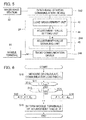
- the arithmetic processing unit 244 performs multiple functions (a load measurement unit 42, an adjustment-value setting unit 44, and an adjustment-value signaling unit 46) by executing a program stored in a memory circuit (not shown). It is possible to use a structure in which the functions of the arithmetic processing unit 244 are distributed to multiple integrated circuits, or a structure in which each of the functions is performed by a dedicated electronic circuit (DSP).
- DSP dedicated electronic circuit
- the load measurement unit 42 measures or calculates an index value (hereinafter referred to as "communication load index") L that indicates communication load of the picobase station 24 itself.
- the communication load index L indicates the communication traffic. For example, the sum of the number of call originations initiated from mobile terminals 14 in the picocell Cp of the picobase station 24 and the number of call terminations to mobile terminals 14 in the picocell Cp in a unit time, or the total number of packets forwarded by the picobase station 24 in a unit time is represented by the communication load index L as the communication traffic.
- the adjustment-value setting unit 44 sets the adjustment value A (variable) of the picobase station 24 itself according to the communication load index L measured by the load measurement unit 42. More specifically, the adjustment-value setting unit 44 sets the adjustment value A at a smaller value when the communication load indicated by the communication load index L is larger. For example, the adjustment-value setting unit 44 may determine the adjustment value A corresponding to the current communication load index L by referring to a table in which adjustment values A are recorded for respective values of the communication load index L. Alternatively, the adjustment-value setting unit 44 may calculate the adjustment value A through a calculation using a predetermined mathematical expression in which the communication load index L is a variable.
- the adjustment value A can be set so as to vary depending on the picobase station 24.
- the adjustment-value signaling unit 46 informs each mobile terminal 14 in the picocell Cp formed by the picobase station 24 itself of the adjustment value A set by the adjustment-value setting unit 44 by using the radio communication device 246. As described above, the adjustment value A is utilized by each mobile terminal 14 for selecting the radio base station 20.
- Fig. 6 is a flowchart of operations of each picobase station 24 in which the arithmetic processing unit 244 sets and signals the adjustment value A .
- the process shown in Fig. 6 is repeated, for example, when interrupts occur at predetermined intervals, and the adjustment value A is updated at each repetition.
- the load measurement unit 42 measures or calculates the current communication load index L of the picobase station 24 itself (S 10).
- the adjustment-value setting unit 44 updates the adjustment value A (S11 through S 14) so that the communication load index L of the picobase station 24 itself becomes close to or falls within a predetermined range (L th1 ⁇ L ⁇ L th2 ).
- the adjustment-value signaling unit 46 informs mobile terminals 14 in the picocell Cp of the updated adjustment value A using the radio communication device 246 (S15), and ends the process in Fig. 6 .
- the adjustment value A is increased, so that the picobase stations 24 become likely to be selected as the access point for mobile terminals 14.
- the adjustment-value setting unit 44 determines whether or not the communication load index L is higher than a predetermined second threshold L th2 (S 13).
- the predetermined value ⁇ 2 may be set, for example, at the value equal to the predetermined value ⁇ 1 .
- the adjustment-value signaling unit 46 informs mobile terminals 14 in the picocell Cp of the updated adjustment value A (S15), and ends the process in Fig. 6 . Therefore, for picobase stations 24 of which communication load is large (of which communication load index L is higher than the threshold L th2 ), the adjustment value A is decreased, so that the picobase stations 24 become difficult to be selected as the access point for the mobile terminals 14.
- the adjustment-value signaling unit 46 informs each mobile terminal 14 of the current adjustment value A that is the same as the adjustment value A at the last process (S15), and ends the process in Fig. 6 .
- the adjustment value A signaled from each picobase station 24 to mobile terminals 14 changes from moment to moment depending on the communication status (acting on the communication load index L) of each picobase station 24. For picobase stations 24 for which communication load is small, the picocells Cp are expanded in effect, so that the picobase stations 24 become likely to be selected as the access point for mobile terminals 14.
- the adjustment value A can be set so as to vary depending on the picobase station 24, the size of each picocell Cp in effect can be adjusted individually depending on the communication load of the picobase station 24. Accordingly, it is possible to alleviate the concentration of connected terminals on specific picobase stations 24 (i.e., to equalize the number of connected terminals at picobase stations 24).
- the adjustment value A may be increased, whereas if the communication load index L is higher than the threshold L th , the adjustment value A may be decreased.
- the adjustment value A in response to change in the communication load, the adjustment value A changes too frequently and the substantial size of the picocell Cp also changes too frequently. This results in a problem in that the number of times of change of the access point for mobile terminals 14 increases significantly.
- the adjustment value A is not changed if the communication load index L is in the range from the threshold L th1 to the threshold L th2 , change in the substantial size of each picocell Cp is restricted.
- the first embodiment thus has an advantage that communications between mobile terminals 14 and picobase stations 24 are stabilized in comparison with the variation in which only a single threshold L th is used.
- Fig. 7 is a block diagram of the picobase station 24 in the second embodiment.
- the arithmetic processing unit 244 in each picobase station 24 serves as a power measurement unit 52, an adjustment-value setting unit 54, and an adjustment-value signaling unit 56 by executing a program stored in a memory circuit. It is possible to use a structure in which the functions of the arithmetic processing unit 244 are distributed to multiple integrated circuits, or a structure in which each of the functions is performed by a dedicated electronic circuit (DSP).
- DSP dedicated electronic circuit
- the radio communication device 246 of the picobase station 24 has a function for receiving radiowaves from the macrobase station 22 that forms the macrocell Cm including the picocell Cp of the picobase station 24 itself, in addition to the function for wireless communication with mobile terminals 14.
- the power measurement unit 52 measures the power (reception power) P of radiowaves that the radio communication device 246 receives from the macrobase station 22. The longer the distance between the picobase station 24 and the macrobase station 22, the less the reception power P. In other words, the reception power P serves as an index indicating the distance between the picobase station 24 and the macrobase station 22.
- the adjustment-value setting unit 54 sets the adjustment value A (variable) of the picobase station 24 itself according to the reception power P measured by the power measurement unit 52. More specifically, the adjustment-value setting unit 54 sets the adjustment value A at a larger value when the reception power P is higher (when the distance between the picobase station 24 and the macrobase station 22 is shorter). For example, the adjustment-value setting unit 44 may determine the adjustment value A corresponding to the reception power P by referring to a table in which adjustment values A are recorded for respective values of the reception power P. Alternatively, the adjustment-value setting unit 44 may calculate the adjustment value A through a calculation using a predetermined mathematical expression in which the reception power P is a variable.
- the adjustment value A can be set so as to vary depending on the picobase station 24.
- the adjustment-value signaling unit 56 informs each mobile terminal 14 in the picocell Cp formed by the picobase station 24 itself of the adjustment value A set by the adjustment-value setting unit 54 by using the radio communication device 246.
- the base-station selection unit 36 selects, from among multiple radio base stations 20 (macrobase station 22 or picobase station 24) that can communicate with the mobile terminal 14, a radio base station 20 for which the received-radiowave characteristic value R obtained by the process of the characteristic-value amendment unit 34 is the maximum.
- the adjustment values A are set at a higher value and the picocells Cp are expanded in effect.
- Radiowaves with high reception power P from the picobase station 24 are received in picocells Cp of picobase stations 24 near the picobase station 24. Accordingly, in a system in which received-radiowave characteristic values R 0 of picobase stations 24 are not adjusted, there is a high probability that the macrobase station 22 is selected as the access point for the mobile terminal 14 even if the mobile terminal 14 is located in any of picocells Cp. In the second embodiment, the shorter the distance to the macrobase station 22, the greater the adjustment value A set for the picobase station 24, and the picocell Cp for the picobase station 24 is substantially expanded.
- the adjustment value A may be set at a small value.
- the picobase station 24 in the location that is very remote from the macrobase station 22 is likely to be selected as the access point for mobile terminals 14 even if the size of picocells Cp is not significantly expanded.
- each picobase station 24 sets the adjustment value A for the picobase station 24 itself, and signals it to each mobile terminal 14.
- the macrobase station 22 sets the adjustment value A for each of multiple picobase stations 24 that form picocells Cp in the macrocell Cm of the macrobase station 22.
- Fig. 8 is a block diagram of the picobase station 24 in the third embodiment.
- the arithmetic processing unit 244 in each picobase station 24 performs multiple functions (a speed estimation unit 62, an adjustment-value setting unit 64, and an adjustment-value signaling unit 66) by executing a program stored in a memory circuit (not shown). It is possible to use a structure in which the functions of the arithmetic processing unit 244 shown in Fig. 8 are distributed to multiple integrated circuits, or a structure in which each of the functions is performed by a dedicated electronic circuit (DSP).
- DSP dedicated electronic circuit
- the speed estimation unit 62 determines a total communication speed T.
- the total communication speed T is an index indicating total communication efficiency among the macrobase station 22 and the multiple picobase stations 24 within the macrocell Cm of the macrobase station 22.
- the total communication speed T coincides with the total sum of the communication speeds (throughputs) of the multiple picobase stations 24 within the macrocell Cm and the communication speed of the macrobase station 22 itself.
- the amount of information forwarded in every unit time by each picobase station 24 is considered to the communication speed of the picobase station 24, and the communication speed is signaled to the macrobase station 22.
- the speed estimation unit 62 calculates the sum of the communication speed of the macrobase station 22 itself and the communication speeds signaled from respective picobase stations 24, as the total communication speed T.
- the adjustment-value setting unit 64 sets the adjustment value A (variable) for each picobase station 24 within the macrocell Cm formed by the macrobase station 22, depending on the total communication speed T. More specifically, the adjustment-value setting unit 64 calculates individually the adjustment values A of the respective picobase stations 24 so as to increase the total communication speed T.
- the adjustment-value signaling unit 66 signals the adjustment value A for each picobase station 24 determined by the adjustment-value setting unit 64 to the picobase station 24 by using the inter-base-station communication device 222.
- Each picobase station 24 signals the adjustment value A signaled from the macrobase station 22 to each mobile terminal 14 within the picocell Cp of the picobase station 24 itself.
- Fig. 9 is a flowchart of operations of the macrobase station 22 for setting and signaling the adjustment value A of each picobase station 24.
- the process shown in Fig. 9 is repeated, for example, when interrupts occur at predetermined intervals.
- the adjustment values A (1) to A (N) for multiple (N) picobase stations 24 corresponding to the macrobase station 22 may be updated at each repetition.
- the speed estimation unit 62 obtains communication speeds of the N picobase stations 24 from the respective picobase stations 24 within the macrocell Cm, and determines the current total communication speed T(0) (S20).
- the adjustment-value setting unit 64 selects a picobase station 24 (hereinafter referred to as a "subject base station 24(n)”) from among the N picobase stations 24 (S21).
- the subsequent process corresponding to steps S22 to S26 (hereinafter referred to as “adjustment value setting process”) is sequentially executed for each of the N picobase stations 24 within the macrocell Cm by applying a different picobase station 24 to the subject base station 24(n) repeatedly, as a result of the negative decision at S27.
- the adjustment-value setting unit 64 increases the current adjustment value A (n) of the subject base station 24(n) by a change amount ⁇ 1 (S22). Then, the speed estimation unit 62 estimates the total communication speed T(n) under the assumption that the adjustment value A (n) for the subject base station 24(n) is increased by the change amount ⁇ 1 (S23). The scheme for estimating the total communication speed T(n) is optional.
- the amount of change in the total communication speed T(n) when the adjustment value A is changed by the change amount ⁇ 1 may be obtained statistically or experimentally in advance, and the speed estimation unit 62 may calculate the current total communication speed T(n) by changing the total communication speed T(n-1) determined at step S23 of the last adjustment value setting process by the amount of change prepared in advance. In the adjustment value setting process of the first round, the speed estimation unit 62 may calculate the current total communication speed T(n) by changing the total communication speed T(0) determined at step S20 by the amount of change prepared in advance.
- the adjustment-value setting unit 64 determines whether or not the total communication speed T(n) determined at step S23 is higher than the total communication speed T(n-1) determined at step S23 of the last adjustment value setting process (i.e., the total communication speed if the adjustment value A (n) of the subject base station 24(n) is not increased) (S24). In the adjustment value setting process of the first round, at step S24, it is determined whether or not the total communication speed T(n) determined at last step S23 is higher than the total communication speed T(0) determined at step S20.
- the adjustment-value signaling unit 66 signals the adjustment value A (n) changed at step S22 to the subject base station 24(n) by using the inter-base-station communication device 222 (S26). In other words, if it is expected that the total communication speed T will increase as a result of increase in the adjustment value A (n), the increased value is fixed as the adjustment value A (n) for the subject base station 24(n).
- the adjustment-value setting unit 64 decreases the adjustment value A (n) increased at step S22 by a change amount ⁇ 2 (S25).
- the change amount ⁇ 2 may be set at, for example, the same value as the change amount ⁇ 1 .
- the adjustment-value signaling unit 66 signals the adjustment value A (n) obtained at step S25 to the subject base station 24(n) by using the inter-base-station communication device 222 (S26).
- the process shown in Fig. 9 ends when the adjustment value setting process has been conducted for all of N picobase stations 24 located in the macrocell Cm of the macrobase station 22 (if the determination at S27 is "yes").
- each of the adjustment values A (1) to A (N) for each picobase station 24 is updated sequentially in every process in Fig. 9 so as to increase the total communication speed T.
- Operations of the mobile terminals 14 that have received the adjustment values A (n) from the picobase stations 24 are the same as those in the first embodiment.
- the third embodiment in a manner similar to the first embodiment, since picocells for multiple picobase stations 24 are expanded in effect, depending on the adjustment values A , it is possible to alleviate the concentration of connected terminals on the macrobase station 22 in comparison with another system in which picocells Cp are not expanded.
- the adjustment value A can be set so as to vary depending on the picobase station 24 individually, it is possible to alleviate the concentration of connected terminals on specific picobase stations 24 (i.e., to equalize the number of connected terminals at picobase stations 24).
- the adjustment value A (n) for each picobase station 24 is set so as to increase the total communication speed T, it is possible to improve the entire communication efficiency in the single macrobase station 22 and N picobase stations 24 corresponding to the macrobase station 22.
- the communication load index L in the first embodiment is not limited to be the communication traffic of the picobase station 24.
- the communication load index L may be the total number of the mobile terminals 14 connected to the picobase station 24 (the number of connected terminals) or the ratio of the resources actually used for communications with mobile terminals 14 to the resources available in the picobase station 24 (the resource usage ratio).
- the resources may be, for example, frequency resource blocks in OFDMA or downlink channelization codes in CDMA.
- the adjustment value A (variable) may be set in accordance with both of the communication load index L exemplified in conjunction with the first embodiment and the reception power P exemplified in conjunction with the second embodiment.
- the adjustment value A may be set in accordance with a weighted sum of the communication load index L and the reception power P.
- the scheme for adjusting the received-radiowave characteristic value R 0 using the adjustment value A may be altered. For example, it is possible to calculate an adjusted received-radiowave characteristic value R by multiplying the adjustment value A by the received-radiowave characteristic value R 0 , or by a predetermined mathematical expression in which the received-radiowave characteristic value R 0 and the adjustment value A are variables.
- the adjustment value A may be calculated in a manner suitable for the scheme for adjusting the received-radiowave characteristic value R 0 .
- the picobase station 24 is exemplified as a radio base station 20 that forms a small sized cell C.
- the sort of the radio base station 20 that forms a cell C within the macrocell Cm may be freely selected.
- a microbase station forming a cell (microcell) C having a radius from several tens of meters to several hundred meters or a femtobase station forming a cell (femtocell) C having a radius of several meters may be used instead of the picobase station 24 in the above-described embodiments.
- the mobile communications network 12 can be comprehended as a communications network including radio base stations 20 forming first cells (e.g., the macrobase stations 22 in the embodiments) and radio base stations 20 forming second cells (e.g., picobase stations 24 in embodiments) of which the size is smaller than that of the first cell.
- the mobile communications network 12 can be understood as a communications network including multiple sorts of radio base station 20 having different transmission powers.
Landscapes
- Engineering & Computer Science (AREA)
- Computer Networks & Wireless Communication (AREA)
- Signal Processing (AREA)
- Mobile Radio Communication Systems (AREA)
Applications Claiming Priority (2)
| Application Number | Priority Date | Filing Date | Title |
|---|---|---|---|
| JP2010268166A JP5465162B2 (ja) | 2010-12-01 | 2010-12-01 | 移動通信網および無線基地局 |
| PCT/JP2011/076424 WO2012073697A1 (ja) | 2010-12-01 | 2011-11-16 | 移動通信網および無線基地局 |
Publications (1)
| Publication Number | Publication Date |
|---|---|
| EP2648458A1 true EP2648458A1 (de) | 2013-10-09 |
Family
ID=46171644
Family Applications (1)
| Application Number | Title | Priority Date | Filing Date |
|---|---|---|---|
| EP11844501.4A Withdrawn EP2648458A1 (de) | 2010-12-01 | 2011-11-16 | Mobiles kommunikationsnetzwerk und drahtlose basisstation |
Country Status (4)
| Country | Link |
|---|---|
| US (1) | US20130336151A1 (de) |
| EP (1) | EP2648458A1 (de) |
| JP (1) | JP5465162B2 (de) |
| WO (1) | WO2012073697A1 (de) |
Families Citing this family (9)
| Publication number | Priority date | Publication date | Assignee | Title |
|---|---|---|---|---|
| JP5855377B2 (ja) * | 2011-07-21 | 2016-02-09 | 株式会社Nttドコモ | 無線通信システム、無線基地局および通信制御方法 |
| WO2014044310A1 (en) * | 2012-09-20 | 2014-03-27 | Telefonaktiebolaget L M Ericsson (Publ) | Method and network node for improving resource utilization of a radio cell |
| CN103037440B (zh) * | 2012-12-13 | 2016-03-02 | 北京北方烽火科技有限公司 | 一种移动负载均衡方法及装置 |
| JPWO2015022952A1 (ja) | 2013-08-13 | 2017-03-02 | 日本電気株式会社 | 無線パラメータ制御装置、無線基地局、無線通信システム、無線パラメータ制御方法、およびプログラム |
| WO2015051837A1 (en) * | 2013-10-09 | 2015-04-16 | Telefonaktiebolaget L M Ericsson (Publ) | Sounding reference signal based small cell activity control |
| JP7253703B2 (ja) * | 2019-03-12 | 2023-04-07 | パナソニックIpマネジメント株式会社 | 位置推定装置および位置推定システム |
| JP7142275B2 (ja) * | 2019-03-25 | 2022-09-27 | パナソニックIpマネジメント株式会社 | 位置推定システム、位置推定装置、および位置推定方法 |
| JP7266240B2 (ja) * | 2019-03-29 | 2023-04-28 | パナソニックIpマネジメント株式会社 | 位置推定装置、位置推定システム、および位置推定方法 |
| WO2020184674A1 (ja) * | 2019-03-12 | 2020-09-17 | パナソニックIpマネジメント株式会社 | 位置推定システム、位置推定装置、および位置推定方法 |
Family Cites Families (8)
| Publication number | Priority date | Publication date | Assignee | Title |
|---|---|---|---|---|
| JP4354779B2 (ja) * | 2003-10-30 | 2009-10-28 | 京セラ株式会社 | 基地局装置及び制御局装置 |
| JP2007520170A (ja) * | 2004-01-27 | 2007-07-19 | テルコーディア テクノロジーズ インコーポレイテッド | Cdmaネットワークパラメータの動的自動最適化のための方法およびシステム |
| JP2006179965A (ja) * | 2004-10-25 | 2006-07-06 | Nec Corp | 無線ネットワーク制御方法、無線通信システム、基地局制御装置 |
| CN101836487B (zh) * | 2007-10-22 | 2015-01-14 | 日本电气株式会社 | 无线通信系统、基站、无线电资源管理方法和基站控制程序 |
| US20090135754A1 (en) * | 2007-11-27 | 2009-05-28 | Qualcomm Incorporated | Interference management in a wireless communication system using overhead channel power control |
| JP5156498B2 (ja) * | 2008-06-18 | 2013-03-06 | 株式会社エヌ・ティ・ティ・ドコモ | 基地局及び移動通信方法 |
| JP5366975B2 (ja) * | 2008-11-28 | 2013-12-11 | パナソニック株式会社 | 無線通信基地局装置及び総送信電力制御方法 |
| US8295874B2 (en) * | 2009-06-10 | 2012-10-23 | Motorola Mobility Llc | Femto-cell power control using idle-mode user equipment in a cellular communication system |
-
2010
- 2010-12-01 JP JP2010268166A patent/JP5465162B2/ja not_active Expired - Fee Related
-
2011
- 2011-11-16 EP EP11844501.4A patent/EP2648458A1/de not_active Withdrawn
- 2011-11-16 WO PCT/JP2011/076424 patent/WO2012073697A1/ja not_active Ceased
- 2011-11-16 US US13/990,983 patent/US20130336151A1/en not_active Abandoned
Non-Patent Citations (1)
| Title |
|---|
| See references of WO2012073697A1 * |
Also Published As
| Publication number | Publication date |
|---|---|
| JP5465162B2 (ja) | 2014-04-09 |
| JP2012119958A (ja) | 2012-06-21 |
| WO2012073697A1 (ja) | 2012-06-07 |
| US20130336151A1 (en) | 2013-12-19 |
Similar Documents
| Publication | Publication Date | Title |
|---|---|---|
| EP2648458A1 (de) | Mobiles kommunikationsnetzwerk und drahtlose basisstation | |
| US11984937B2 (en) | Communication system with beam quality measurement | |
| EP3598835B1 (de) | Direktzugriffsverfahren und -vorrichtung | |
| CN111226351B (zh) | 一种广播波束域调整方法及装置 | |
| EP2773143B1 (de) | Funkkommunikationssystem, funkbasisstation und kommunikationssteuerungsverfahren zum auswählen eines funkzugangspunkt | |
| EP2608428B1 (de) | Adaptiver Filter zur Verwendung in der Funkressourcenverwaltung | |
| US10383048B2 (en) | Cell selection method in wireless network, base station, and user equipment | |
| CN102857970B (zh) | 一种小区间负载平衡的实现方法及装置 | |
| JP5891067B2 (ja) | 通信制御装置および通信制御方法 | |
| CN104813698A (zh) | 在无线通信网络的小区中的频谱之中的选择 | |
| US10154417B2 (en) | Network node and a method therein for computing cell range expansion (CRE) values | |
| CN102823300B (zh) | 执行小区选择的方法和装置 | |
| JP5855377B2 (ja) | 無線通信システム、無線基地局および通信制御方法 | |
| US9998974B2 (en) | Wireless communication terminal, storage medium, and cell selection method | |
| EP2922229A1 (de) | Verfahren, Vorrichtung und System | |
| EP2747472A1 (de) | Drahtloses kommunikationssystem und kommunikationssteuerungsverfahren dafür | |
| US20240422642A1 (en) | Probabilistic mobility load balancing in multi-band mobile communication network | |
| CN113747520A (zh) | 一种小区重选方法及相关装置 | |
| WO2016022050A1 (en) | Radio network node, and method for determining whether a wireless device is a suitable candidate for handover to a target cell for load balancing reasons | |
| CN114727306B (zh) | 阈值配置方法、网络侧设备和计算机可读存储介质 | |
| WO2017099640A1 (en) | Network node and method for managing a comp cluster | |
| CN105874868B (zh) | 一种小区节点、上行干扰处理系统及方法 | |
| CN114554539A (zh) | 业务处理方法、装置、网络设备及存储介质 | |
| JP2015015654A (ja) | 通信制御方法、通信制御装置及び無線通信装置 |
Legal Events
| Date | Code | Title | Description |
|---|---|---|---|
| PUAI | Public reference made under article 153(3) epc to a published international application that has entered the european phase |
Free format text: ORIGINAL CODE: 0009012 |
|
| 17P | Request for examination filed |
Effective date: 20130619 |
|
| AK | Designated contracting states |
Kind code of ref document: A1 Designated state(s): AL AT BE BG CH CY CZ DE DK EE ES FI FR GB GR HR HU IE IS IT LI LT LU LV MC MK MT NL NO PL PT RO RS SE SI SK SM TR |
|
| DAX | Request for extension of the european patent (deleted) | ||
| STAA | Information on the status of an ep patent application or granted ep patent |
Free format text: STATUS: THE APPLICATION HAS BEEN WITHDRAWN |
|
| 18W | Application withdrawn |
Effective date: 20160309 |