EP2649932A1 - Verfahren zur erkennung des blickpunktes und vorrichtung zur detektion der blickpunktes - Google Patents
Verfahren zur erkennung des blickpunktes und vorrichtung zur detektion der blickpunktes Download PDFInfo
- Publication number
- EP2649932A1 EP2649932A1 EP11847335.4A EP11847335A EP2649932A1 EP 2649932 A1 EP2649932 A1 EP 2649932A1 EP 11847335 A EP11847335 A EP 11847335A EP 2649932 A1 EP2649932 A1 EP 2649932A1
- Authority
- EP
- European Patent Office
- Prior art keywords
- cameras
- subject
- gaze
- vector
- vectors
- Prior art date
- Legal status (The legal status is an assumption and is not a legal conclusion. Google has not performed a legal analysis and makes no representation as to the accuracy of the status listed.)
- Withdrawn
Links
Images


Classifications
-
- G—PHYSICS
- G06—COMPUTING OR CALCULATING; COUNTING
- G06F—ELECTRIC DIGITAL DATA PROCESSING
- G06F3/00—Input arrangements for transferring data to be processed into a form capable of being handled by the computer; Output arrangements for transferring data from processing unit to output unit, e.g. interface arrangements
- G06F3/01—Input arrangements or combined input and output arrangements for interaction between user and computer
- G06F3/011—Arrangements for interaction with the human body, e.g. for user immersion in virtual reality
- G06F3/013—Eye tracking input arrangements
-
- A—HUMAN NECESSITIES
- A61—MEDICAL OR VETERINARY SCIENCE; HYGIENE
- A61B—DIAGNOSIS; SURGERY; IDENTIFICATION
- A61B3/00—Apparatus for testing the eyes; Instruments for examining the eyes
- A61B3/10—Objective types, i.e. instruments for examining the eyes independent of the patients' perceptions or reactions
- A61B3/113—Objective types, i.e. instruments for examining the eyes independent of the patients' perceptions or reactions for determining or recording eye movement
-
- G—PHYSICS
- G02—OPTICS
- G02B—OPTICAL ELEMENTS, SYSTEMS OR APPARATUS
- G02B27/00—Optical systems or apparatus not provided for by any of the groups G02B1/00 - G02B26/00, G02B30/00
- G02B27/0093—Optical systems or apparatus not provided for by any of the groups G02B1/00 - G02B26/00, G02B30/00 with means for monitoring data relating to the user, e.g. head-tracking, eye-tracking
-
- G—PHYSICS
- G06—COMPUTING OR CALCULATING; COUNTING
- G06T—IMAGE DATA PROCESSING OR GENERATION, IN GENERAL
- G06T7/00—Image analysis
- G06T7/70—Determining position or orientation of objects or cameras
- G06T7/73—Determining position or orientation of objects or cameras using feature-based methods
-
- G—PHYSICS
- G06—COMPUTING OR CALCULATING; COUNTING
- G06V—IMAGE OR VIDEO RECOGNITION OR UNDERSTANDING
- G06V40/00—Recognition of biometric, human-related or animal-related patterns in image or video data
- G06V40/10—Human or animal bodies, e.g. vehicle occupants or pedestrians; Body parts, e.g. hands
- G06V40/18—Eye characteristics, e.g. of the iris
- G06V40/19—Sensors therefor
-
- G—PHYSICS
- G06—COMPUTING OR CALCULATING; COUNTING
- G06T—IMAGE DATA PROCESSING OR GENERATION, IN GENERAL
- G06T2207/00—Indexing scheme for image analysis or image enhancement
- G06T2207/10—Image acquisition modality
- G06T2207/10004—Still image; Photographic image
- G06T2207/10012—Stereo images
-
- G—PHYSICS
- G06—COMPUTING OR CALCULATING; COUNTING
- G06T—IMAGE DATA PROCESSING OR GENERATION, IN GENERAL
- G06T2207/00—Indexing scheme for image analysis or image enhancement
- G06T2207/30—Subject of image; Context of image processing
- G06T2207/30004—Biomedical image processing
- G06T2207/30041—Eye; Retina; Ophthalmic
Definitions
- the present invention relates to a gaze point detection method and a gaze point detection device for detecting a point of gaze of a subject on a predetermined plane on the basis of an image of the subject.
- a device for detecting a line of sight or a point of gaze of a test subject in a non-contact manner has been considered important in the field of human interaction. If the high-precision line of sight detection technology is put to practical use, such device can be applied to various applications such as monitoring a driver, studying the level of interest in a certain product, and inputting data to a personal computer of a severely disabled person.
- a test subject is caused to gaze at a camera located in a known position and one point on a display screen located in a known position, and a function for calculating a line of sight direction of the test subject from the distance
- These line of sight detection methods are capable of precisely detecting a line of sight, even when the test subject moves his/her head.
- the gaze detection method disclosed in Patent Literature 3 is a method for simultaneously detecting lines of sight of both eyes by using two cameras. According to this method as well, the test subject is required to look at the cameras in order to calibrate the results of detecting the lines of sight.
- Causing the test subject to gaze at a camera means that the test subject is required to gaze at the center of the aperture of the camera (the center of the lens), which makes it difficult to determine the viewpoint of the test subject because the object to be gazed at is ambiguous.
- the viewpoint of the test subject could be determined easily by attaching an obvious target (a marker) to the center of the lens, it becomes difficult to accurately detect the line of sight of the test subject because the target appears on a camera image as an obstacle.
- the camera is installed on the lower side of the front side of the test subject for securing an installation site and the test subject is caused to look at the camera, the pupils of the test subject become small due to near reflexes thereof.
- the test subject has corneal reflexes overlapping with it, which makes it difficult to accurately detect the positions of the pupils from the camera image.
- that is calculated when the test subject looks at the camera has a strong effect on a gain value obtained as a result of calibration, and causes a great error on the viewpoint of the test subject or a line of sight detection result over the entire display screen.
- the present invention was contrived in view of such problems, and an object thereof is to provide a gaze point detection method and a gaze point detection device capable of realizing high-speed and highly accurate gaze point detection while reducing the burden on a test subject.
- a gaze point detection device is a device for detecting a point of gaze of a subject based on face images of the subject, this device having: an N number of cameras for acquiring the face images of the subject; a plurality of light sources; a control circuit for controlling the cameras and the light sources; and an image processing unit for processing image signals output from the N number of cameras, wherein the image processing unit: calculates vectors r based on the face images generated by the N number of cameras, the vectors r each representing an actual distance between a center of a pupil of the subject and a corneal reflection point on a cornea of the subject on which light from the light sources reflects; calculates angles ⁇ of a line of sight of the subject with respect to base lines connecting the center of the pupil and the N number of cameras, based on the vectors r corresponding to the N number of cameras, by using the following formula (1) in use of a function f and M number of undetermined constants (M is a natural number of 3 or more) including at least an offset
- the gaze point detection method or gaze point detection device described above generates the face images of the subject by means of the N number of cameras and the plurality of light sources, calculates the vectors r with respect to the N number of cameras based on the face images, the vectors r each from the corneal reflection point of the subject to the center of the pupil of the subject, and calculates the angles ⁇ of the line of sight with respect to the base lines for the gaze of the subject, corresponding to the N number of cameras, by applying the vectors r to the function f that includes the M number of undetermined constants including the offset vectors r 0 .
- the method or device also derives a plurality of relational expressions based on the angles ⁇ calculated as described above, sets the number of cameras at M x 1/2 or higher, and thereby determines the M number of undetermined constants of the function f by using these relational expressions.
- the line of sight direction and the point of gaze are detected from the face images of the subject.
- automatic correction on the function for calculating the line of sight direction can be executed with a high degree of accuracy, without requiring the subject to gaze at a plurality of specified points or the apertures of the cameras. Consequently, the burden on the subject can be reduced, and high-speed and highly accurate gaze point detection can be performed.
- the gaze point detection method and gaze point detection device can realize high-speed and highly accurate gaze point detection while reducing the burden imposed on a test subject.
- gaze point detection device is a device for detecting a gaze point on a monitor screen of an information processing terminal, such as a personal computer, based on a face image of a subject.
- Fig. 1 is a perspective view showing a gaze point detection device 1 according to a preferred embodiment of the present invention.
- the gaze point detection device 1 has four cameras 2a, 2b, 2c, 2d for capturing face images of a subject A, light sources 3a, 3b, 3c, 3d provided outside imaging lenses of apertures of the cameras 2a, 2b, 2c, 2d, respectively, a light-emitting circuit (control circuit) 4 for feeding power to the light sources 3a, 3b, 3c, 3d, a synchronizing signal generator (control circuit) 5 for generating synchronizing signals to be input to the cameras 2a, 2b 2c, 2d, a delay circuit (control circuit) 6 for delaying the synchronizing signals, an image processor (image processing unit) 7, such as a personal computer, for processing image signals generated by the cameras 2a, 2b, 2c, 2d, and a display device 8 that is disposed above the cameras 2a, 2b and between the cameras 2c, 2d in such a
- the cameras 2a, 2b, 2c, 2d generate image data by capturing images of the face of the subject A.
- Cameras of NTSC system a type of an interlaced scanning system, are used as the cameras 2a, 2b, 2c, 2d.
- 30 frames of image data obtained per second are each composed of an odd field which is constituted by odd horizontal pixel lines and an even field which is constituted by even horizontal pixel lines except for the odd field.
- the image of the odd field and the image of the even field are captured and generated alternately at intervals of 1/60 of a second. Specifically, within one frame, the pixel lines of the odd field and the pixel lines of the even field are generated alternately to be side-by-side.
- the cameras 2a, 2c, 2d receive input of delayed vertical synchronizing signals (VD signals) from the synchronizing signal generator 5 via the delay circuit 6, so that the four cameras 2a, 2b, 2c, 2d capture images at different times.
- VD signals delayed vertical synchronizing signals
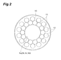
- the light sources 3a, 3b, 3c, 3d are fixed on the outside of the circular apertures 9a, 9b, 9c, 9d accommodating objective lenses of the cameras 2a, 2b, 2c, 2d.
- Fig. 2 shows a plan view of one of the light sources 3a, 3b, 3c, 3d.
- the light sources 3a, 3b, 3c, 3d radiate illumination light toward the face of the subject A, and has a plurality of two types of light-emitting elements 11, 12 embedded in a ring-shaped base part 10.
- the light-emitting elements 11 are semiconductor light-emitting elements (LED) with a center wavelength of 850 nm at their output light, and arranged into a ring at regular intervals along the rim of each of the apertures 9a, 9b, 9c, 9d on the base part 10.
- the light-emitting elements 12 are semiconductor light-emitting elements with a center wavelength of 950 nm at their output light, and arranged on the outside of the light-emitting elements 11 on the base part 10 into a ring at regular intervals.
- each of the light-emitting elements 11, 12 is provided on the base part 10 in such a manner as to emit the illumination light along the optical axis of each of the cameras 2a, 2b, 2c, 2d.
- the configuration of the light sources is not limited the one described above, and therefore other configurations can be employed as long as the cameras are considered as the pinhole camera model.
- the light-emitting circuit 4 is capable of controlling emission timings of the light-emitting elements 11, 12 independently. Specifically, in accordance with the shutter timings of the cameras 2a, 2b, 2c, 2d that are synchronized with the VD signals from the synchronizing signal generator 5, the light-emitting circuit 4 controls the emission timings such that the light-emitting elements 11, 12 emit light alternately.
- Such an operation of the control circuit generates a bright pupil image of left and right eyeballs B of the subject A when the illumination light is radiated from the light-emitting elements 11 to the eyeballs B, and a dark pupil image of the eyeballs B when the illumination light is radiated from the light-emitting elements 12 to the eyeballs B.
- the reasons are as follows: compared to the illumination light having a wavelength longer than 900 nm, the illumination light with a wavelength shorter than 900 nm makes the pupils brighter, but the pupils appear to be darker when the illumination light enters the eyeballs B from a position away from the optical axis of each camera.
- the image processor 7 processes image data output from the four cameras 2a, 2b, 2c, 2d. Specifically, the image processor 7 separates one frame of image data output from the cameras 2a, 2b, 2c, 2d into an odd field and an even field. For example, the image data in the odd field (odd image data) corresponds to the bright pupil image, and the image data in the even field (even image data) corresponds to the dark pupil image. These image data have the valid pixels only in the odd field or the even field. Thus, the image processor 7 generates the bright pupil image data and the dark pupil image data by incorporating the average brightness of the pixel lines of the adjacent valid pixels into a pixel value between the lines.
- the image processor 7 also repeatedly detects the left and right pupils of the subject A using the bright pupil image data and the dark pupil image data. In other words, the image processor 7 generates a difference image between the bright pupil image data and the dark pupil image data, sets a window based on the position of the pupils detected in the previous pupil detection process, and searches for the pupils in this window. More specifically, the image processor 7 binarizes the difference image by a threshold value determined by a percentile method, executes isolated point removal and labeling, and then selects, from labeled pixel connection components, pupil candidates from shape parameters such as the area, size, area ratio, squareness, and pupil feature value which are likely to represent the characteristics of the pupils. Out of the connection components of the selected pupil candidates, the image processor 7 determines two pupil candidates in a certain relationship as the left and right pupils, and calculates the central coordinates of the left and right pupils according to the image data.
- the image processor 7 Based on the bright pupil image data and the dark pupil image data, the image processor 7 also detects the position of a corneal reflection point on the cornea of each of the left and right eyes of the subject A where light from the light sources reflects. In other words, the image processor 7 sets a window having each detected pupil in the middle, creates image data, the resolution of which is increased only in this window, and detects the corneal reflection from the image data. Specifically, the image processor 7 determines a binarization threshold by means of the percentile method, creates a binarized image from this image, executes labeling, and selects a part whose area is equal to or less than a certain value.
- the image processor 7 applies a separability filter to the central coordinates of the selected part, obtains a feature value by multiplying the degree of separability by the brightness, and determines that the corneal reflection is not detected when the feature value is equal or less than a certain value.
- the image processor 7 also calculates the distance in which the corneal reflection moves, and takes this distance as a differential position correction amount.
- the image processor 7 then shifts the corneal reflection positions of the bright and dark pupil image data by the differential position correction amount so that the corneal reflection positions match, adds the brightness of the image data thereto, and determines the resultant brightness centroid coordinates as the coordinates of the corneal reflection.
- the image processor 7 further calculates a three-dimensional position of each of the left and right pupils of the subject A from the pupil center coordinates that are detected based on the image data output from the two cameras 2a, 2b. In so doing, the image processor 7 measures three-dimensional coordinates of each pupil by means of a stereo method.
- the stereo method is a method for previously measuring internal parameters such as the focal lengths of the lenses of the cameras, the centers of images, and pixel sizes, and external parameters such as the positions and orientations of the cameras, and then determining the spatial positions of points in images of a subject captured by a plurality of stereo cameras, based on the coordinates of the points by using the internal and external parameters.
- a world coordinate system (X W , Y W , Z W ) shown in the diagram is a coordinate system in which the origin O W thereof shared by the two cameras 2a, 2b is located in the middle of, for example, the screen of the display device 8.
- a camera coordinate system (X, Y, Z) is a coordinate system in which the origin C thereof is the optical center for the cameras 2a, 2b and the Z-axis is parallel to an optical axis extending from the optical center to be perpendicular to an image surface.
- An image coordinate system (X G , Y G ) is a coordinate system which is parallel to the XY plane along an image surface where image sensors are placed, and in which the intersection point (image center) of the optical axis and the image surface is taken as the origin C i of this coordinate system.
- a point P is taken as a target point
- calibration data in which the world coordinates of the target point P and the image coordinates thereof are associated with each other, need to be acquired in advance.
- Examples of such calibration data include, as the external parameters, a translation vector of the camera coordinate system with respect to the world coordinate system and a rotation matrix of the camera coordinate system with respect to the world coordinate system, and, as the internal parameters, the focal lengths, image center coordinates, scale factors, lens distortion coefficients, and an interval between pixels of the image sensor.
- Such calibration data are acquired beforehand and stored in the image processor 7.
- the image processor 7 acquires relational expressions of pupil center coordinates in the image coordinate system and pupil center coordinates in the world coordinate system, the pupil center coordinates being detected based on the output data of the two cameras 2a, 2b. Subsequently, from these two relational expressions, the image processor 7 obtains three-dimensional position coordinates of the pupils of the subject A in the world coordinate system. The image processor 7 can also obtain the three-dimensional positions of the left and right pupils of the subject A in a similar manner.
- the image processor 7 detects a point of gaze Q of the subject on the display device 8, by using the detected position of left or right corneal reflection point of the subject A and the position of the center of the corresponding pupil.
- a procedure for detecting the point of gaze Q by the image processor 7 is now described with reference to Figs. 4 and 5 ; and a gaze point detection procedure in which only camera images obtained by the cameras 2a, 2b are used is described for simplification.
- a virtual viewpoint plane X'-Y' is set in which a base line OP connecting the origin O and the pupil P is taken as the normal.
- the X'-axis is the same as the intersection of an X W -Y W plane of the world coordinate system and a virtual viewpoint plane X'-Y'.
- the image processor 7 calculates a vector r G from a corneal reflection point G to the center of the pupil P in an image surface S G .
- the vector r G is then converted into the vector r (a vector calculation step), which is the actual size that is obtained using the magnification of the cameras obtained based on the distance OP.
- the cameras 2a, 2b are in the pinhole camera model and that the corneal reflection point G and the center of the pupil P exist on a plane parallel to the virtual viewpoint plane X'-Y'.
- the image processor 7 calculates relative coordinates of the center of the pupil P and the corneal reflection point G to obtain the vector r.
- the vector r represents the actual distance from the corneal reflection point G to the center of the pupil P.
- the image processor 7 determines that an inclination ⁇ of a straight line OT to the horizontal axis X' by setting equal to an inclination ⁇ ' of the vector r to the horizontal axis X G on the image surface.
- the angles ⁇ , ⁇ are calculated by considering that the enlarged vector r on the virtual viewpoint plane corresponds directly to the point of gaze of the subject A, the vector r before being enlarged existing on the plane having the center of the pupil P. More specifically, the angle ⁇ of the line of sight PT of the subject A with respect to the base line OP is assumed to be in a linear relationship with the revised value
- the gain value k and the origin correction vector r 0 vary depending on the subjects A or their left and right eyeballs, the gain value k and the origin correction vector r 0 need to be calibrated. Thus, previously set initial values are corrected by a parameter correction process, which is described hereinafter, and then applied to the gain value k and the origin correction vector r 0 .
- the image processor 7 detects the point of gaze of the subject A on the screen of the display device 8 (a gaze point detection step).
- a coordinate system shown in Fig. 5 is defined in order to describe a gaze point detection mechanism.
- Two virtual viewpoint planes H 1 , H 2 with origins O 1 ', O 2 ' corresponding to the positions of the two cameras 2b, 2a and a virtual viewpoint spherical surface S with a random radius and the center of the pupil P, are defined.
- the two virtual viewpoint planes H 1 , H 2 are perpendicular to straight lines PO 1 ', PO 2 ' respectively.
- the intersection point of the straight line (line of sight) extending between the center of the pupil P and the point of gaze Q on the display screen and the virtual viewpoint spherical surface S is taken as G S , the intersection point of the straight line extending between the center of the pupil P and the origin O 1 ' and the virtual viewpoint spherical surface S as O 1 , and the intersection point of the straight line extending between the center of the pupil P and the origin O 2 ' and the virtual viewpoint spherical surface S as O 2 .
- the angle formed between a straight line O 1 'G 1 and the horizontal axis of the virtual viewpoint plane H 1 becomes ⁇ 1 .
- the angle formed between a straight line O 2 'G 2 and the horizontal axis of the virtual viewpoint plane H 2 becomes ⁇ 2 .
- the angle formed between a curve O 1 G S and the intersection (curve) of the spherical surface S and the horizontal plane extending through the point O 1 is equal to the angle ⁇ 1 .
- the angle formed between a curve O 2 G S and the intersection (curve) of the spherical surface S and the horizontal plane extending through the point O 2 is equal to the angle ⁇ 2 . Because, as described above, the points P, O 1 , O 1 ' exist on the same straight line L 1 and the points P, O 2 , O 2 ' exist on the same straight line L 2 , the angle between the straight line L 1 and the line of sight becomes ⁇ 1 and the angle between the straight line L 2 and the line of sight becomes ⁇ 2 .
- the image processor 7 can calculate the point of gaze on the screen by using the above-described relationships with reference to the data on the previously known position coordinates of the origins O 1 ', O 2 ' and the position and orientation of the display device 8. In other words, the image processor 7 can acquire a relative positional relationship between the points G S , O 1 , O 2 on the virtual viewpoint spherical surface S from the angles ⁇ 1 , ⁇ 2 , ⁇ 1 , ⁇ 2 that are calculated by the camera images captured by the two cameras 2a, 2b.
- the image processor 7, therefore, can uniquely obtain a line of sight PG S from the known coordinates of the origins O 1 ', O 2 ' and the calculated coordinate of the center of the pupil P, and detect the point of gaze Q by calculating the intersection point of the line of sight PG S and the screen of the display device 8.
- the average of these lines of sight can be calculated as a final line of sight vector.
- the function f 1 used by the image processor 7 in the line of sight direction calculation step includes the gain value k and the origin correction vector r 0 as the parameters.
- this gain value k is a magnification used for obtaining the angle ⁇ of the line of sight direction from the vector r between the corneal reflection and the center of the pupil, based on the assumption that the length of the vector (r - r 0 ), which is the adjusted vector r, and the angle ⁇ are in a linear relationship.
- the angle ⁇ should be calculated by simply obtaining the gain value k.
- when the angle ⁇ is zero, in other words, when the subject A gazes at the cameras, the vector
- when the visual axis (gaze) of the eyeball actually does not match the optical axis and moreover the angle ⁇ is equal to zero, the vector
- changes.
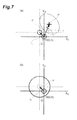
- Fig. 6(c) shows the point of gaze T on the virtual viewpoint plane that includes the position O' of each camera.
- Figs. 6(a), 6(b) and Figs. 7(a), 7(b) each show the vector r that is observed on the image captured by each camera.
- the length of a segment O'T on the virtual viewpoint plane can be calculated using a formula,
- the position of the center of the pupil P is shifted from the corneal reflection G ( Fig. 6(a) ).
- the angle ⁇ ' on the camera images becomes equal to the angle ⁇ on the virtual viewpoint plane.
- the center of the pupil P and the corneal reflection point G on the camera images do not match.
- the corneal reflection point G is shifted to the lower right side of the center of the pupil P.
- the center of the pupil P is further shifted from the corneal reflection G Figs.
- r ⁇ r - r 0
- the parameters k, r 0 described above vary depending on the subjects A, the parameters need to be calibrated beforehand.
- the parameters k, r 0 are undetermined constants in the early stage after activation of the device; thus, appropriate values need to be predetermined by calibrating the parameters, in order to accurately detect the line of sight.
- a parameter correction procedure that is executed by the image processor 7 prior to the gaze point detection process is now described hereinafter.
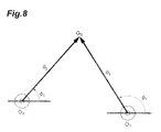
- Fig. 8 is a diagram in which the points O 1 , O 2 , G S projected on the virtual viewpoint spherical surface S of Fig. 5 are further projected onto a plane.
- Vectors ⁇ 1 , ⁇ 2 shown in the diagram represent the angles of the line of sight.
- the vectors r 1 , r 2 are the actual distances between the corneal reflection and the centers of the pupils, which are calculated from the images that are captured by the cameras 2a, 2b when the subject looks at the point G S on the virtual viewpoint spherical surface S.
- the angles ⁇ 1 , ⁇ 2 of line of sight can be calculated from the specified point and applied to the formula (6) together with the vectors r 1 , r 2 in the two relational expressions, so that the two relational expressions have three unknown parameters k, x 0 , y 0 .
- the image processor 7 can calculate the parameters k, x 0 , y 0 and store these parameters as the correction values.
- the gaze point detection device 1 is provided with the four cameras 2a, 2b, 2c, 2d and the four light sources 3a, 3b, 3c, 3d as shown in Fig. 1 , at least three cameras and three light sources may be enough to realize the parameter correction process.
- the parameter correction process described above is executed on thirty frames of camera images obtained within a period of approximately 1 second, and the average value of parameters calculated with respect to frames is stored as the correction value.
- the image processor 7 may use, in place of the formula (3) described above, a function f 2 having a non-linear relationship between a vector
- the image processor 7 may use, in place of the formula (8) described above, a formula that includes a plurality of other non-linear terms such as the square or cube of
- a predetermined number or more cameras are set in the gaze point detection device 1 in order to derive as many relational expressions as not less than the number of parameters requiring correction.
- the specified points at which the subject A is caused to look are preferably not positioned equally away from the cameras but positioned different distances from the cameras in order to deal with non-linear functions.
- the subject A looks at, for example, the right end or the like of the display screen, the distances from each camera to the right end vary from one another; therefore, the non-linear parameters can be obtained accurately, improving the calibration accuracy.
- the angle ⁇ i is used as a scalar quantity to correct the parameters, but the angle ⁇ i may be used as a vector.
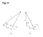
- Fig. 10 shows the angle ⁇ i as a vector on a projection drawing in which a point of the virtual viewpoint spherical surface S is projected onto the plane shown in Fig. 8 .
- the vectors r 1 , r 2 are directly detected from the camera images by the image processor 7, and vectors r 10 , r 20 are the origin correction vectors corresponding to the camera images respectively.
- the x-axes and y-axes of the two-dimensional spaces shown in Figs. 10 and 11 are associated with real number axes and imaginary number axes on complex planes, wherein "j" in the diagrams represent the imaginary unit.
- the vector ⁇ 1 is parallel to the vector r 1 ', and the vector ⁇ 2 is parallel to the vector r 2 '; thus, the following formulae (9) and (10) are established.
- the image processor 7 can therefore calculate and determine the three parameters as the correction values, based on the camera images that are captured by at least the two cameras when the subject A gazes at one specified point.
- the image processor 7 may use a function having a non-linear relationship between the vector
- the following formula (15) is used in place of the formula (9):
- r i ⁇ ⁇ s ⁇ i - t ⁇ ⁇ i 4
- the origin correction vectors r 10 , r 20 are calculated by the following formulae (16) and (17):
- the image processor 7 can further correct the parameters as follows instead of using the formulae (11) and (12).
- the following formula (19) is obtained with reference to Fig. 10 .
- ⁇ 1 - ⁇ 2 O 1 ⁇ O 2 ⁇
- the right side of the formula (19) expresses vectorized angle O 1 PO 2 .
- the image processor 7 can therefore calculate and determine the three parameters as the correction values, based on the camera images that are captured by at least the two cameras when the subject A gazes at one specified point.
- the angle ⁇ i of each line of sight of the subject A to the base line is calculated for each of the four cameras by applying each of the calculated vectors r i to a function.
- the parameters k, r 0 of the function f 1 can be corrected by allowing the subject A to gaze at a plurality of specified points including the apertures of the cameras.
- This is, however, a burden for the subject A to be required to carefully stare at two or more points.
- the margin of error on the correction value of the gain value k expands, and the difference between the point at which the subject A actually gazes and the position of the point of gaze to be detected (gaze point detection error) changes depending on an target position, making the subsequent re-correction complicated.
- the burden on the subject A can be reduced by simply allowing the subject to look at one specified point, and the gaze point detection error can be reduced over the entire display screen because it is not necessary to cause the subject to look at the apertures of the cameras.
- the gaze point detection device 1 and the gaze point detection method according to the present embodiment can be applied to an autism diagnosis support system for a test subject by determining the difference in ratio between a time period during which the test subject looks into the eyes of the opposing person or of a person appearing on the display and a time period during which the test subject looks elsewhere.
- the present invention is not limited to the embodiment described above.
- the gaze point detection method according to the present invention can employ various other aspects of the parameter correction procedure.
- the image processor 7 can complete parameter calibration by executing the following parameter calibration procedure, while the subject A looks at not a predetermined specified point but an adequate position.
- Fig. 12 is a diagram that shows the positional relationship between the point of gaze Q on the screen of the display device 8 and the left and right pupils of the subject A in order to explain the parameter calibration procedure.
- P L and P R respectively represent center coordinates of the left pupil and the right pupil
- the point of gaze Q is a point at which the both eyes of the subject A looks.
- the straight lines P L Q and P R Q represent the visual axes of the left and right eyes respectively.
- Points G 1 ' L and G 2 ' L on the straight line P L Q and points G 1 ' R and G 2 ' R on the straight line P R Q represent the intersection points of two virtual viewpoint planes including the positions O 1 ' and O 2 ' of the cameras 2b, 2a and these straight lines.
- the angles ⁇ of line of sight which are detected in accordance with the left and right eyeballs of the subject A are expressed as ⁇ 1 L , ⁇ 1 R ⁇ 2 L , ⁇ 2 R , and the gain values k and the origin correction vectors r 0 as k L , k R , and r 0 L , r 0 R in accordance with the left and right eyeballs.
- the following formulae (23) to (25) are derived similarly for the angles ⁇ 1 L , ⁇ 2 R and
- the image processor 7 also can execute parameter correction using a relational expression derived by taking angles ⁇ i L , ⁇ i R as vectors.
- a relational expression derived by taking angles ⁇ i L , ⁇ i R as vectors.
- the image processor 7, therefore, can calculate the eight parameters based on the camera images captured by at least the two cameras and determine the calculated parameters as the correction values.
- the image processor 7 may use a function having a non-linear relationship between the vector
- CCD cameras CCD cameras
- CMOS cameras CCD cameras
- other digital cameras may be used as the cameras 2a, 2b, 2c, 2d.
- the function f and the origin correction are determined, and therefore the coefficient k can be obtained accurately. Consequently, the angle ⁇ of line of sight can be calculated more accurately throughout the entire screen where the viewpoints of the subject are detected.
- the line of sight direction calculation step can also calculate the inclination ⁇ of the vector r that is corrected based on the vector r 0 on the face images captured by the N number of cameras.
- the undetermined constant determination step can calculate the M number of undetermined constants by using a plurality of relational expressions derived based at least on the inclination ⁇ and the angle ⁇ . In this case, because the function f is corrected based on the angle of line of sight along the image surface captured by each camera, the corrected line of sight direction can always be calculated accurately, and gaze calculation calibration can be realized while reducing the number of cameras.
- the line of sight direction calculation step can calculate the angles ⁇ corresponding to the N number of cameras when the subject is caused to gaze at a specified point on a predetermined surface.
- the undetermined constant determination step can calculate the M number of undetermined constants based on the position of the specified point and the angle ⁇ .
- the M number of undetermined constants can be determined by causing the subject to gaze at one specified point on a predetermined screen, resulting in a reduction of the burden on the subject and immediate execution of gaze point detection, the burden being imposed at the time of the calibration process.
- the vector calculation step can calculate the vectors r R , r L between the corneal reflection point and the pupil of each of the left and right eyes of the subject based on the face image captured by each of the N number of cameras. Based on the vectors r R , r L corresponding to the N number of cameras, the line of sight direction calculation step can calculate the angles ⁇ R , ⁇ L of lines of sight of the right and left eyes of the subject with respect to the base line of each of the N number of cameras by using the function f.
- the undetermined constant determination step can determine the M number of undetermined constants by using a condition that an intersection points of a predetermined plane with lines of sight of the right and left eyes coincide with each other, based on the angles ⁇ R , ⁇ L corresponding to the N number of cameras. According to this configuration, the function f can be corrected automatically without causing the subject to gaze at a specified point, further reducing the burden that is imposed on the subject at the time of the calibration process.
- the present invention is intended to be used as a method and a device for detecting a point of gaze of a subject on a predetermined plane on the basis of an image of the subject, and is capable of realizing high-speed and highly accurate gaze point detection while reducing the burden imposed on the subject.
- Gaze point detection device 2a, 2b, 2c, 2d ... Camera, 3a, 3b, 3c, 3d ... Light source, 4 ... Light-emitting circuit (control circuit), 5 ... Synchronizing signal generator (control circuit), 6 ... Delay circuit (control circuit), 7 ... Image processor (image processing unit), 8 ... Display device, 9a, 9b, 9c, 9d ... Aperture, A ... Subject, G ... Corneal reflection point, P ... Center of pupil, Q ... Point of gaze, r, r 1 , r 2 ... Vector, r 0 , r 10 , r 20 ... Origin correction vector
Landscapes
- Engineering & Computer Science (AREA)
- Physics & Mathematics (AREA)
- Theoretical Computer Science (AREA)
- General Physics & Mathematics (AREA)
- Health & Medical Sciences (AREA)
- Life Sciences & Earth Sciences (AREA)
- Human Computer Interaction (AREA)
- General Engineering & Computer Science (AREA)
- General Health & Medical Sciences (AREA)
- Ophthalmology & Optometry (AREA)
- Biophysics (AREA)
- Surgery (AREA)
- Veterinary Medicine (AREA)
- Biomedical Technology (AREA)
- Heart & Thoracic Surgery (AREA)
- Medical Informatics (AREA)
- Molecular Biology (AREA)
- Optics & Photonics (AREA)
- Animal Behavior & Ethology (AREA)
- Public Health (AREA)
- Computer Vision & Pattern Recognition (AREA)
- Multimedia (AREA)
- Eye Examination Apparatus (AREA)
- Position Input By Displaying (AREA)
Applications Claiming Priority (2)
| Application Number | Priority Date | Filing Date | Title |
|---|---|---|---|
| JP2010274074 | 2010-12-08 | ||
| PCT/JP2011/078302 WO2012077713A1 (ja) | 2010-12-08 | 2011-12-07 | 注視点検出方法及び注視点検出装置 |
Publications (2)
| Publication Number | Publication Date |
|---|---|
| EP2649932A1 true EP2649932A1 (de) | 2013-10-16 |
| EP2649932A4 EP2649932A4 (de) | 2017-06-14 |
Family
ID=46207199
Family Applications (1)
| Application Number | Title | Priority Date | Filing Date |
|---|---|---|---|
| EP11847335.4A Withdrawn EP2649932A4 (de) | 2010-12-08 | 2011-12-07 | Verfahren zur erkennung des blickpunktes und vorrichtung zur detektion der blickpunktes |
Country Status (4)
| Country | Link |
|---|---|
| US (1) | US9329683B2 (de) |
| EP (1) | EP2649932A4 (de) |
| JP (1) | JP5858433B2 (de) |
| WO (1) | WO2012077713A1 (de) |
Cited By (7)
| Publication number | Priority date | Publication date | Assignee | Title |
|---|---|---|---|---|
| US20130235169A1 (en) * | 2011-06-16 | 2013-09-12 | Panasonic Corporation | Head-mounted display and position gap adjustment method |
| EP2778846A3 (de) * | 2013-03-15 | 2014-12-31 | Tobii Technology AB | Augen-/Blickverfolger und Verfahren zur Verfolgung der Position eines Augen und/der eines Blickpunkts einer Person |
| WO2015108898A1 (en) * | 2014-01-14 | 2015-07-23 | Microsoft Technology Licensing, Llc | Eye gaze detection with multiple light sources and sensors |
| JP2017102688A (ja) * | 2015-12-01 | 2017-06-08 | 株式会社Jvcケンウッド | 視線検出装置及び視線検出方法 |
| EP3185211A4 (de) * | 2014-08-22 | 2018-01-24 | National University Corporation Shizuoka University | Positionsschätzungssystem für hornhautreflexion, positionsschätzungsverfahren für hornhautreflexion, positionsschätzungsprogramm für hornhautreflexion, pupillenerkennungssystem, pupillenerkennungsverfahren, pupillenerkennungsprogramm, blickerfassungssystem, blickerfassungsverfahren, blickerfassungsprogramm, gesichtsausrichtungserkennungssystem und gesichtsausrichtungserkennungsprogramm |
| WO2021059103A1 (en) * | 2019-09-27 | 2021-04-01 | Alcon Inc. | Instant eye gaze calibration systems and methods |
| WO2021059096A1 (en) * | 2019-09-27 | 2021-04-01 | Alcon Inc. | Patient-induced trigger of a measurement for ophthalmic diagnostic devices |
Families Citing this family (41)
| Publication number | Priority date | Publication date | Assignee | Title |
|---|---|---|---|---|
| JPH0645459Y2 (ja) | 1989-02-15 | 1994-11-24 | 三笠産業株式会社 | 輾圧機 |
| US8885882B1 (en) * | 2011-07-14 | 2014-11-11 | The Research Foundation For The State University Of New York | Real time eye tracking for human computer interaction |
| JP5983131B2 (ja) * | 2012-07-19 | 2016-08-31 | 株式会社Jvcケンウッド | 診断支援装置および診断支援方法 |
| JP6217445B2 (ja) * | 2013-03-07 | 2017-10-25 | 株式会社Jvcケンウッド | 診断支援装置および診断支援方法 |
| WO2014188727A1 (ja) * | 2013-05-22 | 2014-11-27 | 国立大学法人神戸大学 | 視線計測装置、視線計測方法および視線計測プログラム |
| JP6217446B2 (ja) * | 2013-06-28 | 2017-10-25 | 株式会社Jvcケンウッド | 制御装置、診断支援装置、制御方法及び制御プログラム |
| JP6142824B2 (ja) * | 2013-07-30 | 2017-06-07 | 株式会社Jvcケンウッド | 診断支援装置および診断支援方法 |
| JP6142822B2 (ja) * | 2013-07-29 | 2017-06-07 | 株式会社Jvcケンウッド | 診断支援装置および診断支援方法 |
| EP2887184A1 (de) * | 2013-12-23 | 2015-06-24 | Movea | Luftzeigestab mit verbesserter Benutzererfahrung |
| JP2015152939A (ja) | 2014-02-10 | 2015-08-24 | ソニー株式会社 | 情報処理装置、情報処理方法、及びプログラム |
| JP6324119B2 (ja) * | 2014-03-04 | 2018-05-16 | 国立大学法人静岡大学 | 回転角度算出方法、注視点検出方法、情報入力方法、回転角度算出装置、注視点検出装置、情報入力装置、回転角度算出プログラム、注視点検出プログラム及び情報入力プログラム |
| JP6361193B2 (ja) * | 2014-03-14 | 2018-07-25 | 富士通株式会社 | 光源装置、発光方法及び端末装置 |
| US10499808B2 (en) * | 2014-06-09 | 2019-12-10 | National University Corporation Shizuoka University | Pupil detection system, gaze detection system, pupil detection method, and pupil detection program |
| KR101610496B1 (ko) * | 2014-08-26 | 2016-04-07 | 현대자동차주식회사 | 시선 추적 방법 및 장치 |
| EP3187100A4 (de) * | 2014-08-29 | 2018-05-09 | Alps Electric Co., Ltd. | Vorrichtung zur sichtlinienerkennung |
| JP6430813B2 (ja) * | 2014-12-25 | 2018-11-28 | 国立大学法人静岡大学 | 位置検出装置、位置検出方法、注視点検出装置、及び画像生成装置 |
| JP2016151798A (ja) * | 2015-02-16 | 2016-08-22 | ソニー株式会社 | 情報処理装置および方法、並びにプログラム |
| JP6327171B2 (ja) * | 2015-02-16 | 2018-05-23 | 株式会社Jvcケンウッド | 注視点検出装置および注視点検出方法 |
| US10061383B1 (en) * | 2015-09-16 | 2018-08-28 | Mirametrix Inc. | Multi-feature gaze tracking system and method |
| KR101697286B1 (ko) * | 2015-11-09 | 2017-01-18 | 경북대학교 산학협력단 | 사용자 스타일링을 위한 증강현실 제공 장치 및 방법 |
| US9880384B2 (en) * | 2015-11-27 | 2018-01-30 | Fove, Inc. | Gaze detection system, gaze point detection method, and gaze point detection program |
| JP6097377B1 (ja) * | 2015-11-27 | 2017-03-15 | 株式会社コロプラ | 画像表示方法及びプログラム |
| JP6631951B2 (ja) * | 2015-12-18 | 2020-01-15 | 国立大学法人静岡大学 | 視線検出装置及び視線検出方法 |
| US10137893B2 (en) * | 2016-09-26 | 2018-11-27 | Keith J. Hanna | Combining driver alertness with advanced driver assistance systems (ADAS) |
| US9898082B1 (en) * | 2016-11-01 | 2018-02-20 | Massachusetts Institute Of Technology | Methods and apparatus for eye tracking |
| US10777018B2 (en) * | 2017-05-17 | 2020-09-15 | Bespoke, Inc. | Systems and methods for determining the scale of human anatomy from images |
| CN107357429B (zh) * | 2017-07-10 | 2020-04-07 | 京东方科技集团股份有限公司 | 用于确定视线的方法、设备和计算机可读存储介质 |
| US11042994B2 (en) | 2017-11-15 | 2021-06-22 | Toyota Research Institute, Inc. | Systems and methods for gaze tracking from arbitrary viewpoints |
| US10564716B2 (en) | 2018-02-12 | 2020-02-18 | Hong Kong Applied Science and Technology Research Institute Company Limited | 3D gazing point detection by binocular homography mapping |
| CN108737642A (zh) * | 2018-04-13 | 2018-11-02 | 维沃移动通信有限公司 | 内容的显示方法及装置 |
| US10324529B1 (en) * | 2018-05-31 | 2019-06-18 | Tobii Ab | Method and system for glint/reflection identification |
| TWI704473B (zh) * | 2018-11-16 | 2020-09-11 | 財團法人工業技術研究院 | 視線向量偵測方向與裝置 |
| US11436756B2 (en) * | 2018-12-20 | 2022-09-06 | Microsoft Technology Licensing, Llc | Calibrating a machine vision camera |
| CN111772572B (zh) * | 2020-05-09 | 2022-12-20 | 温州医科大学 | 一种人眼Kappa角测量装置及Kappa角测量方法 |
| JP7532094B2 (ja) * | 2020-05-29 | 2024-08-13 | キヤノン株式会社 | 観察装置および撮像装置 |
| CN112364765B (zh) * | 2020-11-11 | 2024-12-31 | 京东方科技集团股份有限公司 | 一种人眼运动注视点检测方法及装置 |
| CN115410242B (zh) * | 2021-05-28 | 2026-03-27 | 北京字跳网络技术有限公司 | 视线估计方法和装置 |
| CN113808160B (zh) * | 2021-08-05 | 2024-01-16 | 虹软科技股份有限公司 | 视线方向追踪方法和装置 |
| CN114680889B (zh) * | 2022-03-08 | 2026-02-10 | 中国石油大学(北京) | 钻井作业人员的不安全行为识别方法和装置 |
| SE545952C2 (en) * | 2022-03-31 | 2024-03-26 | Tobii Ab | Dynamic Camera Rotation Calibration |
| CN117037259A (zh) * | 2023-09-22 | 2023-11-10 | 北京中科睿医信息科技有限公司 | 一种眼动信息采集的方法、装置、电子设备及存储介质 |
Family Cites Families (15)
| Publication number | Priority date | Publication date | Assignee | Title |
|---|---|---|---|---|
| US6578962B1 (en) * | 2001-04-27 | 2003-06-17 | International Business Machines Corporation | Calibration-free eye gaze tracking |
| US6659611B2 (en) * | 2001-12-28 | 2003-12-09 | International Business Machines Corporation | System and method for eye gaze tracking using corneal image mapping |
| US7963652B2 (en) * | 2003-11-14 | 2011-06-21 | Queen's University At Kingston | Method and apparatus for calibration-free eye tracking |
| EP1691670B1 (de) * | 2003-11-14 | 2014-07-16 | Queen's University At Kingston | Verfahren und gerät für die kalibrationsfreie augenverfolgung |
| JP4500992B2 (ja) | 2004-01-14 | 2010-07-14 | 国立大学法人静岡大学 | 三次元視点計測装置 |
| JP4517049B2 (ja) | 2003-12-25 | 2010-08-04 | 国立大学法人静岡大学 | 視線検出方法および視線検出装置 |
| WO2005063114A1 (ja) * | 2003-12-25 | 2005-07-14 | National University Corporation Shizuoka University | 視線検出方法および装置ならびに三次元視点計測装置 |
| JP4604190B2 (ja) | 2004-02-17 | 2010-12-22 | 国立大学法人静岡大学 | 距離イメージセンサを用いた視線検出装置 |
| US7686451B2 (en) * | 2005-04-04 | 2010-03-30 | Lc Technologies, Inc. | Explicit raytracing for gimbal-based gazepoint trackers |
| WO2007113975A1 (ja) * | 2006-03-31 | 2007-10-11 | National University Corporation Shizuoka University | 視点検出装置 |
| JP4452836B2 (ja) * | 2006-07-31 | 2010-04-21 | 国立大学法人静岡大学 | 瞳孔を検出する方法及び装置 |
| JP5163982B2 (ja) * | 2008-06-16 | 2013-03-13 | 国立大学法人神戸大学 | 視線計測装置、視線計測プログラム、視線計測方法、および視線計測装置用ディスプレイ |
| US8538044B2 (en) * | 2008-09-26 | 2013-09-17 | Panasonic Corporation | Line-of-sight direction determination device and line-of-sight direction determination method |
| US8371693B2 (en) * | 2010-03-30 | 2013-02-12 | National University Corporation Shizuoka University | Autism diagnosis support apparatus |
| US9135708B2 (en) * | 2010-08-09 | 2015-09-15 | National University Corporation Shizuoka University | Gaze point detection method and gaze point detection device |
-
2011
- 2011-12-07 WO PCT/JP2011/078302 patent/WO2012077713A1/ja not_active Ceased
- 2011-12-07 US US13/992,877 patent/US9329683B2/en not_active Expired - Fee Related
- 2011-12-07 EP EP11847335.4A patent/EP2649932A4/de not_active Withdrawn
- 2011-12-07 JP JP2012547890A patent/JP5858433B2/ja active Active
Non-Patent Citations (1)
| Title |
|---|
| See references of WO2012077713A1 * |
Cited By (19)
| Publication number | Priority date | Publication date | Assignee | Title |
|---|---|---|---|---|
| US20130235169A1 (en) * | 2011-06-16 | 2013-09-12 | Panasonic Corporation | Head-mounted display and position gap adjustment method |
| US9191658B2 (en) * | 2011-06-16 | 2015-11-17 | Panasonic Intellectual Property Management Co., Ltd. | Head-mounted display and position gap adjustment method |
| EP2778846A3 (de) * | 2013-03-15 | 2014-12-31 | Tobii Technology AB | Augen-/Blickverfolger und Verfahren zur Verfolgung der Position eines Augen und/der eines Blickpunkts einer Person |
| WO2015108898A1 (en) * | 2014-01-14 | 2015-07-23 | Microsoft Technology Licensing, Llc | Eye gaze detection with multiple light sources and sensors |
| US9430040B2 (en) | 2014-01-14 | 2016-08-30 | Microsoft Technology Licensing, Llc | Eye gaze detection with multiple light sources and sensors |
| CN105917292A (zh) * | 2014-01-14 | 2016-08-31 | 微软技术许可有限责任公司 | 利用多个光源和传感器的眼睛注视检测 |
| KR20160108388A (ko) * | 2014-01-14 | 2016-09-19 | 마이크로소프트 테크놀로지 라이센싱, 엘엘씨 | 복수의 광원들과 센서들을 사용한 눈 시선 검출 |
| CN105917292B (zh) * | 2014-01-14 | 2019-05-14 | 微软技术许可有限责任公司 | 利用多个光源和传感器的眼睛注视检测 |
| EP3185211A4 (de) * | 2014-08-22 | 2018-01-24 | National University Corporation Shizuoka University | Positionsschätzungssystem für hornhautreflexion, positionsschätzungsverfahren für hornhautreflexion, positionsschätzungsprogramm für hornhautreflexion, pupillenerkennungssystem, pupillenerkennungsverfahren, pupillenerkennungsprogramm, blickerfassungssystem, blickerfassungsverfahren, blickerfassungsprogramm, gesichtsausrichtungserkennungssystem und gesichtsausrichtungserkennungsprogramm |
| US10417782B2 (en) | 2014-08-22 | 2019-09-17 | National University Corporation Shizuoka University | Corneal reflection position estimation system, corneal reflection position estimation method, corneal reflection position estimation program, pupil detection system, pupil detection method, pupil detection program, gaze detection system, gaze detection method, gaze detection program, face orientation detection system, face orientation detection method, and face orientation detection program |
| EP3385911A4 (de) * | 2015-12-01 | 2018-12-19 | JVC KENWOOD Corporation | Sichtliniendetektorvorrichtung und sichtliniendetektionsverfahren |
| JP2017102688A (ja) * | 2015-12-01 | 2017-06-08 | 株式会社Jvcケンウッド | 視線検出装置及び視線検出方法 |
| WO2021059103A1 (en) * | 2019-09-27 | 2021-04-01 | Alcon Inc. | Instant eye gaze calibration systems and methods |
| WO2021059096A1 (en) * | 2019-09-27 | 2021-04-01 | Alcon Inc. | Patient-induced trigger of a measurement for ophthalmic diagnostic devices |
| CN114222521A (zh) * | 2019-09-27 | 2022-03-22 | 爱尔康公司 | 即时眼睛凝视校准系统和方法 |
| CN114269223A (zh) * | 2019-09-27 | 2022-04-01 | 爱尔康公司 | 对眼科诊断装置中的测量的患者引发性触发 |
| US11786119B2 (en) | 2019-09-27 | 2023-10-17 | Alcon Inc. | Instant eye gaze calibration systems and methods |
| AU2020351719B2 (en) * | 2019-09-27 | 2025-08-21 | Alcon Inc. | Instant eye gaze calibration systems and methods |
| AU2020355335B2 (en) * | 2019-09-27 | 2025-08-21 | Alcon Inc. | Patient-induced trigger of a measurement for ophthalmic diagnostic devices |
Also Published As
| Publication number | Publication date |
|---|---|
| JP5858433B2 (ja) | 2016-02-10 |
| JPWO2012077713A1 (ja) | 2014-05-22 |
| US9329683B2 (en) | 2016-05-03 |
| US20130329957A1 (en) | 2013-12-12 |
| EP2649932A4 (de) | 2017-06-14 |
| WO2012077713A1 (ja) | 2012-06-14 |
Similar Documents
| Publication | Publication Date | Title |
|---|---|---|
| US9329683B2 (en) | Method for detecting point of gaze and device for detecting point of gaze | |
| US9135708B2 (en) | Gaze point detection method and gaze point detection device | |
| US8371693B2 (en) | Autism diagnosis support apparatus | |
| EP3153092B1 (de) | Pupillenerkennungssystem, blickerfassungssystem, pupillenerkennungsverfahren und pupillenerkennungsprogramm | |
| US10902635B2 (en) | Line-of-sight detection device | |
| US9514538B2 (en) | Pupil detection method, corneal reflex detection method, facial posture detection method, and pupil tracking method | |
| JP6631951B2 (ja) | 視線検出装置及び視線検出方法 | |
| JP2020034919A (ja) | 構造化光を用いた視線追跡 | |
| JP6324119B2 (ja) | 回転角度算出方法、注視点検出方法、情報入力方法、回転角度算出装置、注視点検出装置、情報入力装置、回転角度算出プログラム、注視点検出プログラム及び情報入力プログラム | |
| JP6596678B2 (ja) | 視線測定装置および視線測定方法 | |
| CN108027977A (zh) | 视线检测装置以及视线检测方法 | |
| EP3385911B1 (de) | Sichtliniendetektorvorrichtung und sichtliniendetektionsverfahren | |
| US10542875B2 (en) | Imaging device, endoscope apparatus, and imaging method | |
| JP6346018B2 (ja) | 眼球計測システム、視線検出システム、眼球計測方法、眼球計測プログラム、視線検出方法、および視線検出プログラム | |
| JP4055858B2 (ja) | 視線検出システム | |
| JP2018108167A (ja) | 視機能検査装置、視機能検査方法、及びコンピュータプログラム | |
| JP6496917B2 (ja) | 視線測定装置および視線測定方法 | |
| JP3834636B2 (ja) | 視線位置計測における頭部の動きのズレを補正する方法及びシステム | |
| JP2016057906A (ja) | 視点位置の計測方法及び計測システム | |
| WO2018123266A1 (ja) | 視機能検査装置、視機能検査方法、及びコンピュータプログラム | |
| JP2024120464A (ja) | 瞳孔検出装置及び瞳孔検出方法 | |
| JP2024090775A (ja) | 視線検出装置、視線検出方法及び視線検出プログラム | |
| JP2018108166A (ja) | 視機能検査装置、視機能検査方法、及びコンピュータプログラム |
Legal Events
| Date | Code | Title | Description |
|---|---|---|---|
| PUAI | Public reference made under article 153(3) epc to a published international application that has entered the european phase |
Free format text: ORIGINAL CODE: 0009012 |
|
| 17P | Request for examination filed |
Effective date: 20130708 |
|
| AK | Designated contracting states |
Kind code of ref document: A1 Designated state(s): AL AT BE BG CH CY CZ DE DK EE ES FI FR GB GR HR HU IE IS IT LI LT LU LV MC MK MT NL NO PL PT RO RS SE SI SK SM TR |
|
| DAX | Request for extension of the european patent (deleted) | ||
| RA4 | Supplementary search report drawn up and despatched (corrected) |
Effective date: 20170516 |
|
| RIC1 | Information provided on ipc code assigned before grant |
Ipc: G02B 27/00 20060101ALI20170510BHEP Ipc: A61B 3/113 20060101AFI20170510BHEP Ipc: G06T 7/73 20170101ALI20170510BHEP Ipc: G06K 9/00 20060101ALI20170510BHEP Ipc: G06F 3/01 20060101ALI20170510BHEP |
|
| 17Q | First examination report despatched |
Effective date: 20190902 |
|
| STAA | Information on the status of an ep patent application or granted ep patent |
Free format text: STATUS: THE APPLICATION IS DEEMED TO BE WITHDRAWN |
|
| 18D | Application deemed to be withdrawn |
Effective date: 20200114 |