EP2650101A1 - Convoyeur à rouleaux pour préformes en matière plastique - Google Patents
Convoyeur à rouleaux pour préformes en matière plastique Download PDFInfo
- Publication number
- EP2650101A1 EP2650101A1 EP13163121.0A EP13163121A EP2650101A1 EP 2650101 A1 EP2650101 A1 EP 2650101A1 EP 13163121 A EP13163121 A EP 13163121A EP 2650101 A1 EP2650101 A1 EP 2650101A1
- Authority
- EP
- European Patent Office
- Prior art keywords
- plastic
- layer
- roller
- base body
- rollers
- Prior art date
- Legal status (The legal status is an assumption and is not a legal conclusion. Google has not performed a legal analysis and makes no representation as to the accuracy of the status listed.)
- Granted
Links
Images


Classifications
-
- B—PERFORMING OPERATIONS; TRANSPORTING
- B65—CONVEYING; PACKING; STORING; HANDLING THIN OR FILAMENTARY MATERIAL
- B65G—TRANSPORT OR STORAGE DEVICES, e.g. CONVEYORS FOR LOADING OR TIPPING, SHOP CONVEYOR SYSTEMS OR PNEUMATIC TUBE CONVEYORS
- B65G47/00—Article or material-handling devices associated with conveyors; Methods employing such devices
- B65G47/22—Devices influencing the relative position or the attitude of articles during transit by conveyors
- B65G47/24—Devices influencing the relative position or the attitude of articles during transit by conveyors orientating the articles
-
- B—PERFORMING OPERATIONS; TRANSPORTING
- B29—WORKING OF PLASTICS; WORKING OF SUBSTANCES IN A PLASTIC STATE IN GENERAL
- B29C—SHAPING OR JOINING OF PLASTICS; SHAPING OF MATERIAL IN A PLASTIC STATE, NOT OTHERWISE PROVIDED FOR; AFTER-TREATMENT OF THE SHAPED PRODUCTS, e.g. REPAIRING
- B29C49/00—Blow-moulding, i.e. blowing a preform or parison to a desired shape within a mould; Apparatus therefor
- B29C49/42—Component parts, details or accessories; Auxiliary operations
- B29C49/4205—Handling means, e.g. transfer, loading or discharging means
- B29C49/42093—Transporting apparatus, e.g. slides, wheels or conveyors
- B29C49/42101—Conveyors, e.g. flat conveyor or clamping between two bands
-
- B—PERFORMING OPERATIONS; TRANSPORTING
- B29—WORKING OF PLASTICS; WORKING OF SUBSTANCES IN A PLASTIC STATE IN GENERAL
- B29C—SHAPING OR JOINING OF PLASTICS; SHAPING OF MATERIAL IN A PLASTIC STATE, NOT OTHERWISE PROVIDED FOR; AFTER-TREATMENT OF THE SHAPED PRODUCTS, e.g. REPAIRING
- B29C49/00—Blow-moulding, i.e. blowing a preform or parison to a desired shape within a mould; Apparatus therefor
- B29C49/42—Component parts, details or accessories; Auxiliary operations
- B29C49/4205—Handling means, e.g. transfer, loading or discharging means
- B29C49/42113—Means for manipulating the objects' position or orientation
- B29C49/42119—Rotation, e.g. rotating a predetermined angle for asymmetric preform or with asymmetric heat profile
-
- B—PERFORMING OPERATIONS; TRANSPORTING
- B65—CONVEYING; PACKING; STORING; HANDLING THIN OR FILAMENTARY MATERIAL
- B65G—TRANSPORT OR STORAGE DEVICES, e.g. CONVEYORS FOR LOADING OR TIPPING, SHOP CONVEYOR SYSTEMS OR PNEUMATIC TUBE CONVEYORS
- B65G37/00—Combinations of mechanical conveyors of the same kind, or of different kinds, of interest apart from their application in particular machines or use in particular manufacturing processes
-
- B—PERFORMING OPERATIONS; TRANSPORTING
- B65—CONVEYING; PACKING; STORING; HANDLING THIN OR FILAMENTARY MATERIAL
- B65G—TRANSPORT OR STORAGE DEVICES, e.g. CONVEYORS FOR LOADING OR TIPPING, SHOP CONVEYOR SYSTEMS OR PNEUMATIC TUBE CONVEYORS
- B65G39/00—Rollers, e.g. drive rollers, or arrangements thereof incorporated in roller-ways or other types of mechanical conveyors
- B65G39/02—Adaptations of individual rollers and supports therefor
-
- B—PERFORMING OPERATIONS; TRANSPORTING
- B65—CONVEYING; PACKING; STORING; HANDLING THIN OR FILAMENTARY MATERIAL
- B65G—TRANSPORT OR STORAGE DEVICES, e.g. CONVEYORS FOR LOADING OR TIPPING, SHOP CONVEYOR SYSTEMS OR PNEUMATIC TUBE CONVEYORS
- B65G39/00—Rollers, e.g. drive rollers, or arrangements thereof incorporated in roller-ways or other types of mechanical conveyors
- B65G39/02—Adaptations of individual rollers and supports therefor
- B65G39/07—Other adaptations of sleeves
-
- B—PERFORMING OPERATIONS; TRANSPORTING
- B65—CONVEYING; PACKING; STORING; HANDLING THIN OR FILAMENTARY MATERIAL
- B65G—TRANSPORT OR STORAGE DEVICES, e.g. CONVEYORS FOR LOADING OR TIPPING, SHOP CONVEYOR SYSTEMS OR PNEUMATIC TUBE CONVEYORS
- B65G47/00—Article or material-handling devices associated with conveyors; Methods employing such devices
- B65G47/22—Devices influencing the relative position or the attitude of articles during transit by conveyors
- B65G47/24—Devices influencing the relative position or the attitude of articles during transit by conveyors orientating the articles
- B65G47/256—Devices influencing the relative position or the attitude of articles during transit by conveyors orientating the articles removing incorrectly orientated articles
-
- B—PERFORMING OPERATIONS; TRANSPORTING
- B29—WORKING OF PLASTICS; WORKING OF SUBSTANCES IN A PLASTIC STATE IN GENERAL
- B29C—SHAPING OR JOINING OF PLASTICS; SHAPING OF MATERIAL IN A PLASTIC STATE, NOT OTHERWISE PROVIDED FOR; AFTER-TREATMENT OF THE SHAPED PRODUCTS, e.g. REPAIRING
- B29C2949/00—Indexing scheme relating to blow-moulding
- B29C2949/07—Preforms or parisons characterised by their configuration
- B29C2949/0715—Preforms or parisons characterised by their configuration the preform having one end closed
-
- B—PERFORMING OPERATIONS; TRANSPORTING
- B29—WORKING OF PLASTICS; WORKING OF SUBSTANCES IN A PLASTIC STATE IN GENERAL
- B29C—SHAPING OR JOINING OF PLASTICS; SHAPING OF MATERIAL IN A PLASTIC STATE, NOT OTHERWISE PROVIDED FOR; AFTER-TREATMENT OF THE SHAPED PRODUCTS, e.g. REPAIRING
- B29C49/00—Blow-moulding, i.e. blowing a preform or parison to a desired shape within a mould; Apparatus therefor
- B29C49/02—Combined blow-moulding and manufacture of the preform or the parison
- B29C49/06—Injection blow-moulding
Definitions
- the present invention relates to a device for transporting plastic containers, in particular plastic preforms.
- plastic preforms a variety of transport devices for conveying plastic containers.
- conveyors for conveying plastic preforms are known.
- plastic preforms are usually first heated in the manufacturing process and then formed in a blow molding machine such as a stretch blow molding machine to plastic containers.
- blow molding machine such as a stretch blow molding machine
- roll sorters are known for this purpose, which have two mutually parallel rotating rollers, between which the plastic preforms are conveyed.
- Such a device is used for example in the DE 601 18 772 T2 described.
- an ejection device is provided which allows ejection of misaligned preforms from the transport system.
- the US 4,223,778 describes another "preform" conveyor of the type described above.
- the rollers are arranged at such a distance from each other that only the end portions of the preforms can fall into the gap formed by the rollers, However, the support rings are held. By a corresponding inclination of these two roles, the plastic preforms can be promoted under the action of gravity.
- roller sorters are usually metal rollers, which must be balanced very precisely.
- plastic preforms are increasingly being processed with very small support rings.
- the plastic preforms slip ever deeper into the intermediate space formed between the two rollers and can sometimes not be properly guided.
- the present invention is therefore based on the object to improve such roller sorters especially for problematic plastic preforms such as plastic preforms with relatively small support ring diameters.
- a device for transporting plastic containers and in particular plastic preforms has a first roller arranged so as to be rotatable about its longitudinal axis and also a second roller which is rotatable about its longitudinal axis.
- the first and second rollers are arranged relative to one another such that the plastic containers can be transported between these rollers, the respective plastic container being supported by both rollers during transport.
- At least one roller has a base body made of a first material and a layer made of a further material differing from the first material and / or a further body surrounding this base body in its circumferential direction (or more generally a further body completely surrounding the main body), this layer acting as Contact layer for contacting the plastic containers (during their transport) is used.
- the further material is a plastic, but it would also be conceivable to use a metal, as explained below.
- both rollers are designed in the manner described, so have the base body made of the first material with the said plastic body surrounding this body.
- the layer has an annular cross-section.
- the base body preferably has a substantially annular cross-section.
- the first material is a plastic.
- other materials such as aluminum.
- Different plastics are understood to mean that the material of the plastic of the main body differs from the plastic of the layer in at least one physical property.
- the containers are advantageously transported in the longitudinal direction of the rollers and in particular the containers are transported under the action of gravity.
- the containers or plastic preforms slide at least temporarily along the rollers in the longitudinal direction of the rollers.
- the rollers are objected to each other in such a way that a main body of the plastic preforms can pass between the rollers and thus a sorting process takes place during the transport.
- the roll in its entirety can be relatively easily and yet stably designed.
- balancing the rollers is not as critical as in the prior art.
- the rotational speed of the rollers can be increased.
- the inventive design allows a very accurate production of the rollers, since any balancing of the high roller speeds can also lead to disturbances.
- reduces the weight of the roll and on the other hand nevertheless ensures the dimensional stability.
- a thickness of the applied or arranged on the body layer is between 0.1 mm and 10 mm, preferably between 0.1 mm and 3 mm and more preferably between 0.1 mm and 1 mm.
- the two rollers have an inclination to a horizontal, which is between 5 degrees and 20 degrees, preferably between 6 degrees and 18 degrees, and more preferably between 7 degrees and 15 degrees.
- the rollers have a rotational speed during operation which is greater than 300 rpm, preferably greater than 350 rpm, preferably greater than 400 rpm and particularly preferably greater than 450 rpm.
- a ratio between the length of the roller and a diameter of the roller is preferably greater than 35, preferably greater than 45, preferably greater than 50 and preferably greater than 60.
- the rollers are formed substantially parallel to each other.
- a radial thickness of the layer is particularly preferably formed smaller than a radial thickness of the base body.
- the radial thickness of the base body is advantageously between 1 mm and 5 mm.
- At least one drive device is provided for driving the rollers.
- two drive means are provided for driving the rollers.
- At least one of these drive devices advantageously has an electric motor.
- the two rollers are driven in opposite directions and although preferably in such a way that the plastic preform is raised by the rotation of the rollers against its gravitational force.
- a friction-reduced and wear-resistant paint can be applied, which can be additionally cured by means of radiation.
- the layer has additional conductive properties, so that no static charge takes place.
- the layer has a radiation-treated plastic and / or a plastic mixed with a plurality of bodies and in particular a multiplicity of spherical bodies.
- the layer is made of a material which is selected from a group of materials which include polyamide (PA), polyetherketone (PEEK), polyoxymethylene (POM), ultra high molecular weight polyethylene (UHMW-PE / PE). UHMW) and the like.
- PA polyamide
- PEEK polyetherketone
- POM polyoxymethylene
- UHMW-PE / PE ultra high molecular weight polyethylene
- the plastic material is treated by radiation and also has a plurality of the above-mentioned, in particular ball-like body.
- the surface structure of the material is formed by or comprises a plurality of spherical elements embedded in a base material and / or carrier material of the guide device or a guide insert.
- these elements in particular spherical elements, made of a material which is selected from a group of materials containing glass or ceramic balls and the like, preferably unipolar fillers.
- these additional bodies for example spherical bodies, each have cross sections or volumes which have a diameter of less than 1 mm, preferably less than 0.1 mm and particularly preferably less than 0.01 mm.
- a proportion by weight of these spherical bodies to the total material is more than 5%, preferably more than 10% and particularly preferably more than 20%.
- the Applicant has also found that radiation-treated plastics (as mentioned above), in particular, radiation-crosslinked plastics, have substantially improved Property, in particular with regard to the friction properties.
- irradiation of plastic materials has been known for some time. Originally it had been searched for a suitable insulation material for cables. It was found that irradiation of certain plastics by radiation induces crosslinking of the plastic and, in addition, degradation of polymers.
- a crosslinking was originally understood to mean a reaction in which a large number of individual macromolecules are linked to form a three-dimensional network. This changes the properties of the material. The aim is, for example, to give polymer materials a greater hardness or temperature resistance.
- a precisely determined amount of energy is introduced into the plastic in the radiation treatment, for example, electron accelerator of different power (for beta rays) or a cobalt-60 source (for gamma rays) can be used.
- electron accelerator of different power for beta rays
- cobalt-60 source for gamma rays
- the layer is made of a material containing fluoropolymers.
- materials as PTFE (polytetrafluoroethylene), PFA (perfluoroalkoxy) or FEP (fluorinated ethylene propylene) have a relatively low adhesion tendency, or a high non-stick effect.
- PFA and FEP are copolymers of PTFA. It is possible to use for coating said materials in pure form, but may preferably be applied to improve the adhesion, a so-called. Primer layer. In addition, a primer system could be applied, which may also have multiple layers.
- adhesion promoter additives for example pigments, heat stabilizers and / or binder resins
- other components can be stored in the coating such as hard, abrasion resistant components. In this case, the layer thickness can be increased.
- the layer contains a metal or is a metal layer.
- this is a means of (metal) flame spraying applied layer. Flame spraying is one of the thermal coating processes. With this method, powder-wire, cord and rod-shaped materials can be processed and sprayed onto component surfaces. In addition, however, ceramics or plastics can be sprayed with this method.
- the plastic containers are in particular PET containers.
- the radiation treatment of the plastics is preferably an irradiation or crosslinking of these plastics by gamma and / or beta rays.
- at least the guide surface facing the containers has a plastic treated by radiation.
- the guide device is constructed from at least two components.
- gamma rays have a high permeability at a relatively low dose rate. In terms of application technology, this means that in the electron accelerators the dose is applied to the blasting material within seconds, whereas several hours are required in a gamma system for this purpose.
- gamma rays can have a greater advantage.
- electron beams are advantageously used.
- the base body to a carbon fiber-containing material and is particularly preferably made of a carbon fiber-containing material, in particular a carbon fiber material.
- a carbon fiber-containing material is particularly lightweight and dimensionally stable and therefore well suited as a starting material for the role.
- carbon is selected as a roll core.
- carbon has the disadvantage that its coefficients of friction are relatively high and thereby a sliding of the plastic preforms, for example, at a gradient of 9 degrees not allows. Therefore, said carbon core or base body is coated with a plastic that specifically reduces the coefficient of friction.
- the above-mentioned layers are particularly suitable for this purpose.
- the base body on a glass fiber reinforced plastic GRP
- GRP glass fiber reinforced plastic
- Such a fiberglass material is particularly lightweight and dimensionally stable, therefore also well suited as a starting material for the role.
- fiberglass is also selected as a roll core, but also has the disadvantage that its coefficients of friction are relatively high and thereby does not allow sliding of the plastic preforms, for example, at a gradient of 9 degrees.
- the roll diameter can be reduced overall and at the same time its surface can also be friction-optimized.
- the base body is designed as a hollow body. Also in this way the mass of the entire roll can be reduced.
- At least one roller and preferably both rollers have a diameter which is between 30 mm and 90 mm, preferably between 35 mm and 60 mm and particularly preferably between 35 mm and 50 mm.
- the device has an ejection device for ejecting or ejecting plastic preforms and in particular for ejecting or ejecting incorrectly oriented plastic preforms.
- a kicker wheel arranged above the transport path of the plastic preforms may be provided which ejects incorrectly oriented plastic preforms or also nesting plastic preforms.
- a holding-down element can also be provided, which orientates the plastic preforms more precisely with respect to the two rollers.
- the present invention is further directed to a transport roller for a device of the type described above.
- this roller has a base body made of a first material and in particular made of a plastic, as well as a body surrounding this body in the circumferential direction of a further and from the first Plastic distinctive plastic-made layer.
- This layer serves as a contact layer for contacting the plastic containers.
- this layer consists of a specific material for a base body and arranged around this body layer.
- this layer completely surrounds the base body in the circumferential direction and completely covers it particularly preferably also in its longitudinal direction.
- the base body comprises a plastic containing carbon fibers and / or the layer comprises a radiation-treated plastic and / or a plastic mixed with a multiplicity of spherical bodies.
- the present invention further relates to a method for transporting plastic containers and in particular plastic preforms.
- the plastic preforms are transported between a first at least temporarily rotating about its longitudinal axis roller and a second support body, wherein the plastic preforms are supported during their transport both from the first roller and from the second support body.
- At least the first roller and / or the second support body has a base body made of a first material, and a base body in its circumferential direction (in the case of the support body at least partially) surrounding, made of a further and different from the first material material Layer, wherein this layer at least temporarily contacts the plastic preforms during their transport.
- plastic containers and in particular plastic preforms are moved relative to a coating of the type described above.
- the plastic preforms are preferably supported below their support ring of the roller and the support body.
- the second support body is also a roller which rotates at least temporarily about its longitudinal axis.
- the second support body it would also be possible for the second support body to be a strip and in particular a straight strip.
- the plastic preforms are also conveyed under the action of gravity, or at least partially along a sloping transport path.
- Fig. 1 shows a schematic view of a device according to the invention or a roller sorter 1 according to the prior art.
- two rollers 2 and 4 are provided (the roller 4 is visible only to a small extent, since it is otherwise covered), which are arranged parallel to each other.
- the plastic preforms can be transported along a predetermined transport path P.
- the plastic preforms are transported in a straight line by the roller sorter.
- the reference symbols L1 and L2 relate to the longitudinal directions of the rollers 2, 4
- the plastic preforms can, for example, pass from a chute (not shown) to these two rollers 2, 4, and in the course of transport are oriented in such a way that whose support rings are supported by the two rollers 2, 4 and the base body of the plastic preforms move between the rollers.
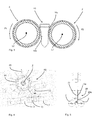
- Fig. 2 shows a schematic representation of a roll according to the invention.
- This role here has a base 22, which is made in particular of carbon fibers.
- This main body 22 is enclosed by a completely surrounding layer 24.
- a radial thickness d1 of this layer 24 is less than a radial thickness d2 of the main body 22.
- webs may be provided, which protrude radially inwards, so that the roller about its longitudinal direction L1 (here perpendicular to extending the plane of the figure) can be driven in rotation.
- the reference numerals A and B indicate the diameter of the roller 2.
- the roller 4 is preferably carried out accordingly.
- Fig. 3 illustrates the transport of the plastic preforms 10 through the two rollers 2 and 4.
- the plastic preform 10 is guided between the two rollers and only the support ring 10a is supported on the two rollers 2, 4 from.
- the main body 10b of the plastic preforms 10 does not touch the two rollers or only occasionally. Nevertheless, however, the layer 24 is advantageously designed such that a frictional resistance with the plastic preforms is minimized.
- the reference numerals P1 and P2 illustrate the directions of rotation of the two rollers 2, 4. By this opposite rotation, the plastic preforms, as known per se from the prior art, better aligned.
- the reference symbols L1 and L2 relate to the longitudinal directions of the plastic preforms 10, which are perpendicular to the figure plane here.
- the transport path of the plastic preforms 10 also runs perpendicular to the plane of the figure.
- Fig. 4 shows a further schematic representation of a device according to the invention 1. It can be seen that above the two rollers 2, 4 and thus also above the transport path of the plastic preforms 10 is provided in its entirety designated 60 ejection or discharge device.
- This ejection device has a wheel 66 rotatable with respect to an axis Z, on which a plurality of (radially) outwardly projecting ejection elements 68 are arranged, which thus also rotate about the axis Z.
- a plastic preform is poorly oriented, for example, as in the figure shown inserted in another plastic preform 10, it can be detected by an ejector 68 and ejected.
- other types of ejection mechanisms would be conceivable.
- it would be possible that one of the rollers 2, 4 or a segment of a roller 2, 4 is displaced perpendicular to the transport path of the plastic preforms, so that the corresponding plastic preform can fall down from the sorter.
- the reference numeral 62 refers to a hold-down element, which can also serve to eject poorly oriented plastic preforms.
- Fig. 5 shows a corresponding further view of in Fig. 4 shown device.
- the ejection element 68 which has a recess 68a directly above the transport path of the plastic preforms, so that correctly transported plastic preforms can not be grasped by this ejection element.
- Reference numeral 72 denotes a guide rail with inclined surfaces 72a. If a plastic preform is conveyed with incorrect orientation, it is laterally urged by this guide rail and can then be ejected from the ejection element 68.
- FIGS. 6a, 6b show a further embodiment of a material according to the invention, which can be used in particular for the layer 24 application.
- a plurality of here substantially spherical bodies 40 are embedded in the main body 45 of the material of the layer 24.
- Fig. 6b shows a view of the body Fig. 6a along the arrows XX Fig. 6 , It can be seen that a contact surface is formed here by these individual spherical bodies 40.
- the elevations caused by the spherical bodies 40 are here shown to be hemispherical, but the invention is not limited thereto. Overall, however, a hilly guide surface is created in this way and it has been shown that this hilly guide surface lowers the coefficient of friction of the surface of the roller 2, 4 or of the layer.
- this embedding of the spherical body is preferably combined with beam crosslinking of the plastic material.
- additional reinforcing elements can be provided, which reinforce the material of the plastic as a whole.
- FIGS. 7a, 7b show a further embodiment in which elevations 41 and / or depressions 42 are provided in the material. These elevations and depressions may also be provided as uniform grooves or grooves or with a different profiling. Overall, this achieves the result that the resulting surface of the roll 2, 4 or of the layer which can be in contact with the plastic preforms has an overall smaller contact surface in the area of contact with the plastic containers.
Landscapes
- Engineering & Computer Science (AREA)
- Mechanical Engineering (AREA)
- Manufacturing & Machinery (AREA)
- Rollers For Roller Conveyors For Transfer (AREA)
- Processing And Handling Of Plastics And Other Materials For Molding In General (AREA)
- Laminated Bodies (AREA)
- Rolls And Other Rotary Bodies (AREA)
Applications Claiming Priority (1)
| Application Number | Priority Date | Filing Date | Title |
|---|---|---|---|
| DE102012103079A DE102012103079A1 (de) | 2012-04-10 | 2012-04-10 | Rollenförderer für Kunststoffvorformlinge |
Publications (2)
| Publication Number | Publication Date |
|---|---|
| EP2650101A1 true EP2650101A1 (fr) | 2013-10-16 |
| EP2650101B1 EP2650101B1 (fr) | 2016-12-21 |
Family
ID=48095634
Family Applications (1)
| Application Number | Title | Priority Date | Filing Date |
|---|---|---|---|
| EP13163121.0A Active EP2650101B1 (fr) | 2012-04-10 | 2013-04-10 | Convoyeur à rouleaux pour préformes en matière plastique |
Country Status (4)
| Country | Link |
|---|---|
| US (1) | US9409723B2 (fr) |
| EP (1) | EP2650101B1 (fr) |
| CN (1) | CN103358431B (fr) |
| DE (1) | DE102012103079A1 (fr) |
Cited By (3)
| Publication number | Priority date | Publication date | Assignee | Title |
|---|---|---|---|---|
| WO2021235931A1 (fr) | 2020-05-18 | 2021-11-25 | Moba Group B.V. | Pièce renforcée de fibres de carbone de forme cylindrique et son procédé de fabrication |
| NL2026105B1 (nl) | 2020-05-18 | 2021-12-03 | Moba Group Bv | Machineonderdeel |
| WO2023241837A1 (fr) * | 2022-06-13 | 2023-12-21 | Krones Ag | Directlink de trieuse à rouleaux |
Families Citing this family (10)
| Publication number | Priority date | Publication date | Assignee | Title |
|---|---|---|---|---|
| DE102012103080A1 (de) * | 2012-04-10 | 2013-10-10 | Krones Ag | Vorrichtung zum Behandeln von Kunststoffbehältnissen mit reibungsreduzierenden Führungseinrichtungen |
| US9944156B2 (en) | 2013-04-05 | 2018-04-17 | Webasto-Edscha Cabrio GmbH | Convertible top with frame locking mechanism |
| GB2530336A (en) * | 2014-09-22 | 2016-03-23 | Stratec Biomedical Ag | Device for transportation Separation and Orientation of cuvettes |
| DE102015205984A1 (de) * | 2015-04-02 | 2016-10-06 | Krones Aktiengesellschaft | Verfahren und Führungssystem für den Transport von Behältern oder Behälter-komponenten in Industrieanlagen für die Behälterherstellung und/oder Produktabfüllung |
| JP6765388B2 (ja) * | 2015-06-23 | 2020-10-07 | ソシエテ・デ・プロデュイ・ネスレ・エス・アー | カプセル送出デバイス |
| DE102017107723A1 (de) * | 2017-04-10 | 2018-10-11 | Krones Ag | Rollensortierer zum Transportieren von Kunststoffvorformlingen |
| WO2019023802A1 (fr) * | 2017-08-01 | 2019-02-07 | Mi Intégration S.E.N.C. | Dispositif et procédé de réduction du frottement entre des objets élastiques et des surfaces |
| EP4413203A4 (fr) | 2021-10-06 | 2025-11-12 | Blue Ocean Closures Ab | Procédé de moulage par pressage d'un produit en fibre en forme de coupe, moule de presse à fibres et produit en fibre en forme de coupe |
| US11845612B2 (en) * | 2021-12-13 | 2023-12-19 | Philip Aubin | Friction drive wheel construction |
| US12391488B1 (en) * | 2024-12-19 | 2025-08-19 | Ralphs-Pugh Co., Inc. | High-release driven conveyor roller |
Citations (8)
| Publication number | Priority date | Publication date | Assignee | Title |
|---|---|---|---|---|
| US4223778A (en) | 1978-05-12 | 1980-09-23 | Owens-Illinois, Inc. | Parison handling assemblies and methods for handling parisons |
| US5044061A (en) * | 1983-09-12 | 1991-09-03 | The B. F. Goodrich Company | Rubber-plastic composite |
| EP1057931A2 (fr) * | 1999-06-02 | 2000-12-06 | Voith Sulzer Papiertechnik Patent GmbH | Rouleau élastique et procédé de fabrication d' un tel rouleau |
| DE10213379A1 (de) * | 2002-03-20 | 2003-10-02 | Paul Sauer Gmbh & Co Walzenfab | Walze mit fluorpolymerhaltigem Bezug |
| DE60118772T2 (de) | 2000-11-03 | 2007-05-03 | Sidel Participations | Zufuhrsystem für vorformen insbesondere geeignet für eine behälter blasmaschine |
| EP2072427A1 (fr) * | 2007-12-17 | 2009-06-24 | Krones AG | Dispositif de tri |
| US20110058760A1 (en) * | 2008-11-28 | 2011-03-10 | David Brian Magnus | Bearing Assembly Comprising Woven Synthetic Fibres |
| EP2303733B1 (fr) * | 2008-07-17 | 2012-01-04 | M. Tanner AG | Dispositif et procédé pour séparer des corps cylindriques |
Family Cites Families (21)
| Publication number | Priority date | Publication date | Assignee | Title |
|---|---|---|---|---|
| BE654048A (fr) * | 1963-10-10 | |||
| HU162656B (fr) * | 1971-12-03 | 1973-03-28 | ||
| DE4122322C2 (de) * | 1991-07-05 | 1994-03-17 | Roland Man Druckmasch | Beschichtete Papierleitwalze |
| DE29701547U1 (de) * | 1997-01-30 | 1997-03-20 | Voith Sulzer Papiermaschinen GmbH, 89522 Heidenheim | Walze für Auftragseinrichtung |
| JPH10218418A (ja) * | 1997-02-14 | 1998-08-18 | Noritsu Koki Co Ltd | 搬送用ローラおよびその製造方法 |
| EP1178764B1 (fr) * | 1999-04-21 | 2006-05-31 | Howmedica Osteonics Corp. | Procede de preparation d'un dispositif medical prothetique en polyethylene selectivement reticule, et dispositif ainsi produit |
| DE19919569B4 (de) * | 1999-04-29 | 2011-07-07 | Voith Patent GmbH, 89522 | Elastische Walze und Verfahren zum Herstellen einer solchen |
| DE29912271U1 (de) * | 1999-07-14 | 1999-09-30 | Ohligschläger, Hans-Joachim, 51469 Bergisch Gladbach | Belag für Förderbandrollen |
| DE29920618U1 (de) * | 1999-11-24 | 2000-02-24 | Holzma-Maschinenbau GmbH, 75365 Calw | Friktionsrolle |
| DE10002683C2 (de) * | 2000-01-24 | 2003-11-06 | Paul Sauer Gmbh & Co Walzenfab | Walze mit farbabweisendem Bezug |
| US6716148B1 (en) * | 2001-07-17 | 2004-04-06 | Double E Co., Inc. | Metal-sleeved carbon fiber anilox roller base |
| US7147596B2 (en) * | 2002-02-26 | 2006-12-12 | Reynolds Ronald W | Low-mass roller or pulley |
| US6918865B2 (en) * | 2002-10-31 | 2005-07-19 | Voith Paper Patent Gmbh | Roll cover |
| FR2864050B1 (fr) * | 2003-12-23 | 2007-04-06 | Sidel Sa | Systeme d'alimentation de preformes comportant un dispositif d'elimination selective des preformes mal positionnees de type allonge |
| DE102006021035B4 (de) * | 2006-04-27 | 2014-03-06 | Paul Sauer Gmbh & Co. Walzenfabrik Kg | Walze mit elastomerer Beschichtung |
| DE102007046156A1 (de) | 2007-09-27 | 2009-04-02 | Schaeffler Kg | Reibbelag sowie verschleißfestes Bauteil |
| ES2347886T5 (es) * | 2007-11-27 | 2013-12-26 | La Seda De Barcelona S.A. | Aparato para poner en orden y alinear preformas |
| CH699222A1 (de) * | 2008-07-17 | 2010-01-29 | M Tanner Ag | Vorrichtung und Verfahren zum Vereinzeln von zylindrischen Körpern. |
| DE102008042684A1 (de) * | 2008-10-08 | 2010-04-15 | Voith Patent Gmbh | Walze |
| DE102010005475A1 (de) * | 2010-01-23 | 2011-07-28 | Schaeffler Technologies GmbH & Co. KG, 91074 | Förderrolle für eine Rollenförderanlage |
| DE102010008367A1 (de) | 2010-02-17 | 2011-08-18 | Krones Ag, 93073 | Rollensortiereinrichtung und Sortierverfahren zum Sortieren von Vorformlingen sowie Transportvorrichtung mit solcher Rollensortiereinrichtung |
-
2012
- 2012-04-10 DE DE102012103079A patent/DE102012103079A1/de not_active Ceased
-
2013
- 2013-04-10 US US13/860,087 patent/US9409723B2/en active Active
- 2013-04-10 CN CN201310123451.XA patent/CN103358431B/zh active Active
- 2013-04-10 EP EP13163121.0A patent/EP2650101B1/fr active Active
Patent Citations (8)
| Publication number | Priority date | Publication date | Assignee | Title |
|---|---|---|---|---|
| US4223778A (en) | 1978-05-12 | 1980-09-23 | Owens-Illinois, Inc. | Parison handling assemblies and methods for handling parisons |
| US5044061A (en) * | 1983-09-12 | 1991-09-03 | The B. F. Goodrich Company | Rubber-plastic composite |
| EP1057931A2 (fr) * | 1999-06-02 | 2000-12-06 | Voith Sulzer Papiertechnik Patent GmbH | Rouleau élastique et procédé de fabrication d' un tel rouleau |
| DE60118772T2 (de) | 2000-11-03 | 2007-05-03 | Sidel Participations | Zufuhrsystem für vorformen insbesondere geeignet für eine behälter blasmaschine |
| DE10213379A1 (de) * | 2002-03-20 | 2003-10-02 | Paul Sauer Gmbh & Co Walzenfab | Walze mit fluorpolymerhaltigem Bezug |
| EP2072427A1 (fr) * | 2007-12-17 | 2009-06-24 | Krones AG | Dispositif de tri |
| EP2303733B1 (fr) * | 2008-07-17 | 2012-01-04 | M. Tanner AG | Dispositif et procédé pour séparer des corps cylindriques |
| US20110058760A1 (en) * | 2008-11-28 | 2011-03-10 | David Brian Magnus | Bearing Assembly Comprising Woven Synthetic Fibres |
Cited By (3)
| Publication number | Priority date | Publication date | Assignee | Title |
|---|---|---|---|---|
| WO2021235931A1 (fr) | 2020-05-18 | 2021-11-25 | Moba Group B.V. | Pièce renforcée de fibres de carbone de forme cylindrique et son procédé de fabrication |
| NL2026105B1 (nl) | 2020-05-18 | 2021-12-03 | Moba Group Bv | Machineonderdeel |
| WO2023241837A1 (fr) * | 2022-06-13 | 2023-12-21 | Krones Ag | Directlink de trieuse à rouleaux |
Also Published As
| Publication number | Publication date |
|---|---|
| EP2650101B1 (fr) | 2016-12-21 |
| US20130264174A1 (en) | 2013-10-10 |
| CN103358431A (zh) | 2013-10-23 |
| CN103358431B (zh) | 2016-12-28 |
| US9409723B2 (en) | 2016-08-09 |
| DE102012103079A1 (de) | 2013-10-10 |
Similar Documents
| Publication | Publication Date | Title |
|---|---|---|
| EP2650101B1 (fr) | Convoyeur à rouleaux pour préformes en matière plastique | |
| EP2404832B1 (fr) | Parapet pour un dispositif de transport de bouteilles en PET | |
| EP1866223B1 (fr) | Dispositif et procede pour redresser des ebauches destinees a produire des produits en plastique par soufflage sur matrice | |
| EP2861403B1 (fr) | Dispositif de séparation de préformes pourvu d'un mécanisme permettant d'éliminer les préformes mal positionnées | |
| EP2836357B1 (fr) | Chaîne convoyeuse pour conteneurs en plastique | |
| DE102012107088A1 (de) | Vorrichtung und Verfahren zum Transportieren von Kunststoffbehältnissen | |
| WO2017097481A2 (fr) | Machine de traitement de récipients et dispositif de transport de récipients | |
| DE102016122462A1 (de) | Vorrichtung zum Sortieren und Fördern von Behälterverschlüssen | |
| EP2650238B1 (fr) | Dispositif de traitement de récipients en plastique avec des guides à frottement réduit | |
| EP2861405B1 (fr) | Dispositif et procédé de transport de préformes | |
| DE602004001132T2 (de) | Ausrichtungsvorrichtung für flaschenvorformen zur hindurchführung durch eine blasmaschine | |
| WO2017064186A1 (fr) | Dispositif de stockage intermédiaire et procédé de stockage intermédiaire | |
| EP3277607B1 (fr) | Procédé et système de guidage pour le transport de récipients ou de composants de récipients dans des installations industrielles pour la fabrication de récipients et/ou le remplissage de produit | |
| WO2018065227A1 (fr) | Dispositif permettant de trier des marchandises de détail comprenant un dispositif de dosage | |
| EP2861404B1 (fr) | Dispositif de transport de préformes | |
| EP3592675B1 (fr) | Machine de traitement de récipients et dispositif de transport de récipients | |
| DE102017107199A1 (de) | Fördereinrichtung | |
| EP3609673B1 (fr) | Canal de fluide, procédé de fabrication de ce dernier et installation de traitement de contenants | |
| DE102017107723A1 (de) | Rollensortierer zum Transportieren von Kunststoffvorformlingen | |
| EP3098186B1 (fr) | Dispositif de transport d'une bande de materiau debout | |
| DE202024105553U1 (de) | Vorrichtung zum Höhentransportieren von Behältern von einem ersten Maschinenabschnitt zu einem zweiten Maschinenabschnitt | |
| DE102005046508A1 (de) | Verfahren und Vorrichtung zum Transport von Vorformlingen |
Legal Events
| Date | Code | Title | Description |
|---|---|---|---|
| PUAI | Public reference made under article 153(3) epc to a published international application that has entered the european phase |
Free format text: ORIGINAL CODE: 0009012 |
|
| AK | Designated contracting states |
Kind code of ref document: A1 Designated state(s): AL AT BE BG CH CY CZ DE DK EE ES FI FR GB GR HR HU IE IS IT LI LT LU LV MC MK MT NL NO PL PT RO RS SE SI SK SM TR |
|
| AX | Request for extension of the european patent |
Extension state: BA ME |
|
| 17P | Request for examination filed |
Effective date: 20140327 |
|
| RBV | Designated contracting states (corrected) |
Designated state(s): AL AT BE BG CH CY CZ DE DK EE ES FI FR GB GR HR HU IE IS IT LI LT LU LV MC MK MT NL NO PL PT RO RS SE SI SK SM TR |
|
| 17Q | First examination report despatched |
Effective date: 20140718 |
|
| RIC1 | Information provided on ipc code assigned before grant |
Ipc: B65G 47/14 20060101ALI20160311BHEP Ipc: B29C 49/42 20060101AFI20160311BHEP Ipc: B65G 39/06 20060101ALI20160311BHEP |
|
| GRAP | Despatch of communication of intention to grant a patent |
Free format text: ORIGINAL CODE: EPIDOSNIGR1 |
|
| INTG | Intention to grant announced |
Effective date: 20160713 |
|
| GRAS | Grant fee paid |
Free format text: ORIGINAL CODE: EPIDOSNIGR3 |
|
| GRAA | (expected) grant |
Free format text: ORIGINAL CODE: 0009210 |
|
| AK | Designated contracting states |
Kind code of ref document: B1 Designated state(s): AL AT BE BG CH CY CZ DE DK EE ES FI FR GB GR HR HU IE IS IT LI LT LU LV MC MK MT NL NO PL PT RO RS SE SI SK SM TR |
|
| REG | Reference to a national code |
Ref country code: GB Ref legal event code: FG4D Free format text: NOT ENGLISH |
|
| REG | Reference to a national code |
Ref country code: CH Ref legal event code: EP |
|
| REG | Reference to a national code |
Ref country code: IE Ref legal event code: FG4D Free format text: LANGUAGE OF EP DOCUMENT: GERMAN |
|
| REG | Reference to a national code |
Ref country code: AT Ref legal event code: REF Ref document number: 855095 Country of ref document: AT Kind code of ref document: T Effective date: 20170115 |
|
| REG | Reference to a national code |
Ref country code: DE Ref legal event code: R096 Ref document number: 502013005807 Country of ref document: DE |
|
| PG25 | Lapsed in a contracting state [announced via postgrant information from national office to epo] |
Ref country code: LV Free format text: LAPSE BECAUSE OF FAILURE TO SUBMIT A TRANSLATION OF THE DESCRIPTION OR TO PAY THE FEE WITHIN THE PRESCRIBED TIME-LIMIT Effective date: 20161221 |
|
| REG | Reference to a national code |
Ref country code: FR Ref legal event code: PLFP Year of fee payment: 5 |
|
| REG | Reference to a national code |
Ref country code: LT Ref legal event code: MG4D |
|
| REG | Reference to a national code |
Ref country code: NL Ref legal event code: MP Effective date: 20161221 |
|
| PG25 | Lapsed in a contracting state [announced via postgrant information from national office to epo] |
Ref country code: LT Free format text: LAPSE BECAUSE OF FAILURE TO SUBMIT A TRANSLATION OF THE DESCRIPTION OR TO PAY THE FEE WITHIN THE PRESCRIBED TIME-LIMIT Effective date: 20161221 Ref country code: GR Free format text: LAPSE BECAUSE OF FAILURE TO SUBMIT A TRANSLATION OF THE DESCRIPTION OR TO PAY THE FEE WITHIN THE PRESCRIBED TIME-LIMIT Effective date: 20170322 Ref country code: SE Free format text: LAPSE BECAUSE OF FAILURE TO SUBMIT A TRANSLATION OF THE DESCRIPTION OR TO PAY THE FEE WITHIN THE PRESCRIBED TIME-LIMIT Effective date: 20161221 Ref country code: NO Free format text: LAPSE BECAUSE OF FAILURE TO SUBMIT A TRANSLATION OF THE DESCRIPTION OR TO PAY THE FEE WITHIN THE PRESCRIBED TIME-LIMIT Effective date: 20170321 |
|
| PG25 | Lapsed in a contracting state [announced via postgrant information from national office to epo] |
Ref country code: HR Free format text: LAPSE BECAUSE OF FAILURE TO SUBMIT A TRANSLATION OF THE DESCRIPTION OR TO PAY THE FEE WITHIN THE PRESCRIBED TIME-LIMIT Effective date: 20161221 Ref country code: FI Free format text: LAPSE BECAUSE OF FAILURE TO SUBMIT A TRANSLATION OF THE DESCRIPTION OR TO PAY THE FEE WITHIN THE PRESCRIBED TIME-LIMIT Effective date: 20161221 Ref country code: RS Free format text: LAPSE BECAUSE OF FAILURE TO SUBMIT A TRANSLATION OF THE DESCRIPTION OR TO PAY THE FEE WITHIN THE PRESCRIBED TIME-LIMIT Effective date: 20161221 |
|
| PG25 | Lapsed in a contracting state [announced via postgrant information from national office to epo] |
Ref country code: NL Free format text: LAPSE BECAUSE OF FAILURE TO SUBMIT A TRANSLATION OF THE DESCRIPTION OR TO PAY THE FEE WITHIN THE PRESCRIBED TIME-LIMIT Effective date: 20161221 |
|
| PG25 | Lapsed in a contracting state [announced via postgrant information from national office to epo] |
Ref country code: SK Free format text: LAPSE BECAUSE OF FAILURE TO SUBMIT A TRANSLATION OF THE DESCRIPTION OR TO PAY THE FEE WITHIN THE PRESCRIBED TIME-LIMIT Effective date: 20161221 Ref country code: IS Free format text: LAPSE BECAUSE OF FAILURE TO SUBMIT A TRANSLATION OF THE DESCRIPTION OR TO PAY THE FEE WITHIN THE PRESCRIBED TIME-LIMIT Effective date: 20170421 Ref country code: RO Free format text: LAPSE BECAUSE OF FAILURE TO SUBMIT A TRANSLATION OF THE DESCRIPTION OR TO PAY THE FEE WITHIN THE PRESCRIBED TIME-LIMIT Effective date: 20161221 Ref country code: EE Free format text: LAPSE BECAUSE OF FAILURE TO SUBMIT A TRANSLATION OF THE DESCRIPTION OR TO PAY THE FEE WITHIN THE PRESCRIBED TIME-LIMIT Effective date: 20161221 Ref country code: CZ Free format text: LAPSE BECAUSE OF FAILURE TO SUBMIT A TRANSLATION OF THE DESCRIPTION OR TO PAY THE FEE WITHIN THE PRESCRIBED TIME-LIMIT Effective date: 20161221 |
|
| PG25 | Lapsed in a contracting state [announced via postgrant information from national office to epo] |
Ref country code: SM Free format text: LAPSE BECAUSE OF FAILURE TO SUBMIT A TRANSLATION OF THE DESCRIPTION OR TO PAY THE FEE WITHIN THE PRESCRIBED TIME-LIMIT Effective date: 20161221 Ref country code: PL Free format text: LAPSE BECAUSE OF FAILURE TO SUBMIT A TRANSLATION OF THE DESCRIPTION OR TO PAY THE FEE WITHIN THE PRESCRIBED TIME-LIMIT Effective date: 20161221 Ref country code: ES Free format text: LAPSE BECAUSE OF FAILURE TO SUBMIT A TRANSLATION OF THE DESCRIPTION OR TO PAY THE FEE WITHIN THE PRESCRIBED TIME-LIMIT Effective date: 20161221 Ref country code: PT Free format text: LAPSE BECAUSE OF FAILURE TO SUBMIT A TRANSLATION OF THE DESCRIPTION OR TO PAY THE FEE WITHIN THE PRESCRIBED TIME-LIMIT Effective date: 20170421 Ref country code: BG Free format text: LAPSE BECAUSE OF FAILURE TO SUBMIT A TRANSLATION OF THE DESCRIPTION OR TO PAY THE FEE WITHIN THE PRESCRIBED TIME-LIMIT Effective date: 20170321 |
|
| REG | Reference to a national code |
Ref country code: DE Ref legal event code: R097 Ref document number: 502013005807 Country of ref document: DE |
|
| PLBE | No opposition filed within time limit |
Free format text: ORIGINAL CODE: 0009261 |
|
| STAA | Information on the status of an ep patent application or granted ep patent |
Free format text: STATUS: NO OPPOSITION FILED WITHIN TIME LIMIT |
|
| 26N | No opposition filed |
Effective date: 20170922 |
|
| PG25 | Lapsed in a contracting state [announced via postgrant information from national office to epo] |
Ref country code: DK Free format text: LAPSE BECAUSE OF FAILURE TO SUBMIT A TRANSLATION OF THE DESCRIPTION OR TO PAY THE FEE WITHIN THE PRESCRIBED TIME-LIMIT Effective date: 20161221 |
|
| REG | Reference to a national code |
Ref country code: CH Ref legal event code: PL |
|
| GBPC | Gb: european patent ceased through non-payment of renewal fee |
Effective date: 20170410 |
|
| REG | Reference to a national code |
Ref country code: IE Ref legal event code: MM4A |
|
| PG25 | Lapsed in a contracting state [announced via postgrant information from national office to epo] |
Ref country code: MC Free format text: LAPSE BECAUSE OF FAILURE TO SUBMIT A TRANSLATION OF THE DESCRIPTION OR TO PAY THE FEE WITHIN THE PRESCRIBED TIME-LIMIT Effective date: 20161221 |
|
| PG25 | Lapsed in a contracting state [announced via postgrant information from national office to epo] |
Ref country code: SI Free format text: LAPSE BECAUSE OF FAILURE TO SUBMIT A TRANSLATION OF THE DESCRIPTION OR TO PAY THE FEE WITHIN THE PRESCRIBED TIME-LIMIT Effective date: 20161221 Ref country code: LU Free format text: LAPSE BECAUSE OF NON-PAYMENT OF DUE FEES Effective date: 20170410 Ref country code: GB Free format text: LAPSE BECAUSE OF NON-PAYMENT OF DUE FEES Effective date: 20170410 Ref country code: LI Free format text: LAPSE BECAUSE OF NON-PAYMENT OF DUE FEES Effective date: 20170430 Ref country code: CH Free format text: LAPSE BECAUSE OF NON-PAYMENT OF DUE FEES Effective date: 20170430 |
|
| REG | Reference to a national code |
Ref country code: FR Ref legal event code: PLFP Year of fee payment: 6 |
|
| REG | Reference to a national code |
Ref country code: BE Ref legal event code: MM Effective date: 20170430 |
|
| PG25 | Lapsed in a contracting state [announced via postgrant information from national office to epo] |
Ref country code: IE Free format text: LAPSE BECAUSE OF NON-PAYMENT OF DUE FEES Effective date: 20170410 |
|
| PG25 | Lapsed in a contracting state [announced via postgrant information from national office to epo] |
Ref country code: BE Free format text: LAPSE BECAUSE OF NON-PAYMENT OF DUE FEES Effective date: 20170430 |
|
| PG25 | Lapsed in a contracting state [announced via postgrant information from national office to epo] |
Ref country code: MT Free format text: LAPSE BECAUSE OF FAILURE TO SUBMIT A TRANSLATION OF THE DESCRIPTION OR TO PAY THE FEE WITHIN THE PRESCRIBED TIME-LIMIT Effective date: 20161221 |
|
| REG | Reference to a national code |
Ref country code: AT Ref legal event code: MM01 Ref document number: 855095 Country of ref document: AT Kind code of ref document: T Effective date: 20180410 |
|
| PG25 | Lapsed in a contracting state [announced via postgrant information from national office to epo] |
Ref country code: HU Free format text: LAPSE BECAUSE OF FAILURE TO SUBMIT A TRANSLATION OF THE DESCRIPTION OR TO PAY THE FEE WITHIN THE PRESCRIBED TIME-LIMIT; INVALID AB INITIO Effective date: 20130410 |
|
| PG25 | Lapsed in a contracting state [announced via postgrant information from national office to epo] |
Ref country code: CY Free format text: LAPSE BECAUSE OF NON-PAYMENT OF DUE FEES Effective date: 20161221 Ref country code: AT Free format text: LAPSE BECAUSE OF NON-PAYMENT OF DUE FEES Effective date: 20180410 |
|
| PG25 | Lapsed in a contracting state [announced via postgrant information from national office to epo] |
Ref country code: MK Free format text: LAPSE BECAUSE OF FAILURE TO SUBMIT A TRANSLATION OF THE DESCRIPTION OR TO PAY THE FEE WITHIN THE PRESCRIBED TIME-LIMIT Effective date: 20161221 |
|
| PG25 | Lapsed in a contracting state [announced via postgrant information from national office to epo] |
Ref country code: TR Free format text: LAPSE BECAUSE OF FAILURE TO SUBMIT A TRANSLATION OF THE DESCRIPTION OR TO PAY THE FEE WITHIN THE PRESCRIBED TIME-LIMIT Effective date: 20161221 |
|
| PG25 | Lapsed in a contracting state [announced via postgrant information from national office to epo] |
Ref country code: AL Free format text: LAPSE BECAUSE OF FAILURE TO SUBMIT A TRANSLATION OF THE DESCRIPTION OR TO PAY THE FEE WITHIN THE PRESCRIBED TIME-LIMIT Effective date: 20161221 |
|
| P01 | Opt-out of the competence of the unified patent court (upc) registered |
Effective date: 20230523 |
|
| PGFP | Annual fee paid to national office [announced via postgrant information from national office to epo] |
Ref country code: FR Payment date: 20250310 Year of fee payment: 13 |
|
| PGFP | Annual fee paid to national office [announced via postgrant information from national office to epo] |
Ref country code: IT Payment date: 20250320 Year of fee payment: 13 |
|
| PGFP | Annual fee paid to national office [announced via postgrant information from national office to epo] |
Ref country code: DE Payment date: 20250305 Year of fee payment: 13 |