EP2303733B1 - Dispositif et procédé pour séparer des corps cylindriques - Google Patents
Dispositif et procédé pour séparer des corps cylindriques Download PDFInfo
- Publication number
- EP2303733B1 EP2303733B1 EP09797340A EP09797340A EP2303733B1 EP 2303733 B1 EP2303733 B1 EP 2303733B1 EP 09797340 A EP09797340 A EP 09797340A EP 09797340 A EP09797340 A EP 09797340A EP 2303733 B1 EP2303733 B1 EP 2303733B1
- Authority
- EP
- European Patent Office
- Prior art keywords
- cylindrical bodies
- guide elements
- ejection
- separating device
- guide
- Prior art date
- Legal status (The legal status is an assumption and is not a legal conclusion. Google has not performed a legal analysis and makes no representation as to the accuracy of the status listed.)
- Active
Links
Images



Classifications
-
- B—PERFORMING OPERATIONS; TRANSPORTING
- B65—CONVEYING; PACKING; STORING; HANDLING THIN OR FILAMENTARY MATERIAL
- B65G—TRANSPORT OR STORAGE DEVICES, e.g. CONVEYORS FOR LOADING OR TIPPING, SHOP CONVEYOR SYSTEMS OR PNEUMATIC TUBE CONVEYORS
- B65G47/00—Article or material-handling devices associated with conveyors; Methods employing such devices
- B65G47/02—Devices for feeding articles or materials to conveyors
- B65G47/04—Devices for feeding articles or materials to conveyors for feeding articles
- B65G47/12—Devices for feeding articles or materials to conveyors for feeding articles from disorderly-arranged article piles or from loose assemblages of articles
- B65G47/14—Devices for feeding articles or materials to conveyors for feeding articles from disorderly-arranged article piles or from loose assemblages of articles arranging or orientating the articles by mechanical or pneumatic means during feeding
- B65G47/1492—Devices for feeding articles or materials to conveyors for feeding articles from disorderly-arranged article piles or from loose assemblages of articles arranging or orientating the articles by mechanical or pneumatic means during feeding the articles being fed from a feeding conveyor
-
- B—PERFORMING OPERATIONS; TRANSPORTING
- B29—WORKING OF PLASTICS; WORKING OF SUBSTANCES IN A PLASTIC STATE IN GENERAL
- B29C—SHAPING OR JOINING OF PLASTICS; SHAPING OF MATERIAL IN A PLASTIC STATE, NOT OTHERWISE PROVIDED FOR; AFTER-TREATMENT OF THE SHAPED PRODUCTS, e.g. REPAIRING
- B29C49/00—Blow-moulding, i.e. blowing a preform or parison to a desired shape within a mould; Apparatus therefor
- B29C49/42—Component parts, details or accessories; Auxiliary operations
- B29C49/4205—Handling means, e.g. transfer, loading or discharging means
- B29C49/42065—Means specially adapted for transporting preforms
-
- B—PERFORMING OPERATIONS; TRANSPORTING
- B65—CONVEYING; PACKING; STORING; HANDLING THIN OR FILAMENTARY MATERIAL
- B65G—TRANSPORT OR STORAGE DEVICES, e.g. CONVEYORS FOR LOADING OR TIPPING, SHOP CONVEYOR SYSTEMS OR PNEUMATIC TUBE CONVEYORS
- B65G47/00—Article or material-handling devices associated with conveyors; Methods employing such devices
- B65G47/22—Devices influencing the relative position or the attitude of articles during transit by conveyors
- B65G47/24—Devices influencing the relative position or the attitude of articles during transit by conveyors orientating the articles
- B65G47/256—Devices influencing the relative position or the attitude of articles during transit by conveyors orientating the articles removing incorrectly orientated articles
-
- B—PERFORMING OPERATIONS; TRANSPORTING
- B65—CONVEYING; PACKING; STORING; HANDLING THIN OR FILAMENTARY MATERIAL
- B65G—TRANSPORT OR STORAGE DEVICES, e.g. CONVEYORS FOR LOADING OR TIPPING, SHOP CONVEYOR SYSTEMS OR PNEUMATIC TUBE CONVEYORS
- B65G47/00—Article or material-handling devices associated with conveyors; Methods employing such devices
- B65G47/52—Devices for transferring articles or materials between conveyors i.e. discharging or feeding devices
- B65G47/525—Devices for transferring articles or materials between conveyors i.e. discharging or feeding devices using fluid jets
-
- B—PERFORMING OPERATIONS; TRANSPORTING
- B29—WORKING OF PLASTICS; WORKING OF SUBSTANCES IN A PLASTIC STATE IN GENERAL
- B29C—SHAPING OR JOINING OF PLASTICS; SHAPING OF MATERIAL IN A PLASTIC STATE, NOT OTHERWISE PROVIDED FOR; AFTER-TREATMENT OF THE SHAPED PRODUCTS, e.g. REPAIRING
- B29C2949/00—Indexing scheme relating to blow-moulding
- B29C2949/07—Preforms or parisons characterised by their configuration
- B29C2949/0715—Preforms or parisons characterised by their configuration the preform having one end closed
-
- B—PERFORMING OPERATIONS; TRANSPORTING
- B29—WORKING OF PLASTICS; WORKING OF SUBSTANCES IN A PLASTIC STATE IN GENERAL
- B29C—SHAPING OR JOINING OF PLASTICS; SHAPING OF MATERIAL IN A PLASTIC STATE, NOT OTHERWISE PROVIDED FOR; AFTER-TREATMENT OF THE SHAPED PRODUCTS, e.g. REPAIRING
- B29C49/00—Blow-moulding, i.e. blowing a preform or parison to a desired shape within a mould; Apparatus therefor
- B29C49/02—Combined blow-moulding and manufacture of the preform or the parison
- B29C49/06—Injection blow-moulding
-
- B—PERFORMING OPERATIONS; TRANSPORTING
- B29—WORKING OF PLASTICS; WORKING OF SUBSTANCES IN A PLASTIC STATE IN GENERAL
- B29C—SHAPING OR JOINING OF PLASTICS; SHAPING OF MATERIAL IN A PLASTIC STATE, NOT OTHERWISE PROVIDED FOR; AFTER-TREATMENT OF THE SHAPED PRODUCTS, e.g. REPAIRING
- B29C49/00—Blow-moulding, i.e. blowing a preform or parison to a desired shape within a mould; Apparatus therefor
- B29C49/42—Component parts, details or accessories; Auxiliary operations
- B29C49/4205—Handling means, e.g. transfer, loading or discharging means
- B29C49/42051—Means for stripping, aligning or de-stacking
- B29C49/42057—Aligning disorderly arranged preforms, e.g. delivered disorderly
-
- B—PERFORMING OPERATIONS; TRANSPORTING
- B29—WORKING OF PLASTICS; WORKING OF SUBSTANCES IN A PLASTIC STATE IN GENERAL
- B29C—SHAPING OR JOINING OF PLASTICS; SHAPING OF MATERIAL IN A PLASTIC STATE, NOT OTHERWISE PROVIDED FOR; AFTER-TREATMENT OF THE SHAPED PRODUCTS, e.g. REPAIRING
- B29C49/00—Blow-moulding, i.e. blowing a preform or parison to a desired shape within a mould; Apparatus therefor
- B29C49/42—Component parts, details or accessories; Auxiliary operations
- B29C49/4205—Handling means, e.g. transfer, loading or discharging means
- B29C49/42051—Means for stripping, aligning or de-stacking
- B29C49/42059—Aligning of preforms getting stuck, unaligned or stacked during transport
Definitions
- the invention relates to the field of separation of bulk material, in particular a device and a method for separating cylindrical bodies according to the preamble of the corresponding independent claims.
- preforms of PET bottles are delivered in bulk form as bulk goods in large containers and guided via a feeding device to a separating device.
- the separating device straightens up the preforms and forms an individual row of the preforms, which leaves the separating device, for example via a chute pointing downwards, also called a drainage rail.
- the preforms pass to inspection and conveying equipment and finally to a stretch blow molder where their cylindrical body is inflated to a desired bottle shape.
- the preforms typically have at one open end a threaded head with a threaded neck and a collar or support ring, which has a larger diameter than the rest of the cylindrical part of the preform.
- DE 601 18 772 T2 describes a separating device, which is designed as a roller conveyor. This has two spaced-apart rollers, which at the funnel-shaped bottom of an elongated container are arranged. The rollers rotate about their longitudinal axes and form a conveyor track, which usually runs with a slight incline. The preforms are transported in a single row in succession through this roller conveyor. For this they rest with their collars on the rollers, whereby due to gravity, their bodies hang down freely with the cylinder part in the gap between the rollers.
- Preforms which do not occupy the correct position or are interleaved and therefore protrude above a predetermined height, are thrown out of the conveyor track by means of a rotating kicker wheel or stuntstaurades and get into a rear region of the roller conveyor or in an overflow area, from where they again in one Be promoted filling container of the roller conveyor.
- This device comprises a roller conveyor for preforms with two rotating rollers and then a drain with rigid rails.
- a roller conveyor for preforms with two rotating rollers and then a drain with rigid rails.
- DE 601 18 722 T2 In the area of the roller conveyor is an arrangement according to the above-mentioned DE 601 18 722 T2 that means a kicker wheel arranged.
- this kicker wheel preforms lying horizontally between the two rotating rollers can not be caught and ejected.
- the device therefore has in the following areas of the sequence, or the rigid rails, a horizontally and in the conveying direction directed detection device, which can detect collar of horizontal preforms.
- a horizontally lying preform If a horizontally lying preform is detected, a portion of one of the two rails is moved away laterally by means of an actuating element to the conveying direction and the false preforms fall down. During this process, however, correctly positioned preforms also fall out of the drainage area and the series of preforms slipping from above must be stopped, which leads to faults. Since the lateral extension of the rail section relatively large masses must be moved, this process is also relatively slow. As a result, the promotion of preforms is slowed down and it may cause additional interference.
- the disclosed horizontal detection device can only correct the preforms lying horizontally between the rails detect. It is very prone to failure, for example, by obliquely hanging preforms and must therefore be aligned very accurately. Therefore, for example, preforms that rest with the collar on the collar of an adjacent preform can not be detected and removed.
- the invention is intended to ensure that hitherto undetectable positional errors and also detectable with the known systems Positional errors of preforms with high reliability are detected and corrected automatically.
- the singulating device is designed for cylindrical bodies, such as preforms for hollow bodies, which have at least one protrusion or a support ring at a first end and at a second end have a diameter which is smaller than the diameter of the protrusion.
- the separating device has a pair of guide elements arranged in parallel, between which the cylindrical bodies can be erected, in that the cylindrical bodies each hang with the projection on the guide elements, ie point downward with the second end.
- the cylindrical bodies form a single row along the guide elements and are thus feasible to a sequence for advancing the cylindrical body.
- the separating device has a detection and ejection device arranged in the region of the guide element, which cylindrical bodies hang with the protrusion on the guide elements, but whose second end does not hang down, or when two or more cylindrical bodies are inserted into each other or nested, detected and ejected from the single row.
- Such a misalignment can occur, for example, if the lower end of the cylindrical body is too wide due to manufacturing defects or tolerances and thereby gets caught on the guide elements rather than turning down into the vertical position.
- Another cause may be that two preforms interfit and thus remain together in a horizontal position between the guide elements or that the intermeshing cylindrical bodies or preforms hang obliquely or even correctly downwards, but with the first upper end over a normal height profile protrude.
- it is detected that a preform is present but not oriented correctly, and then the ejection is triggered. There is thus a presence as well as a location detection available.
- the detection device is an optoelectronic sensor, which optics, image sensor and processor comprises, and this optoelectronic sensor, seen in the transport direction of the preforms, at the beginning region of the partial range of the guide elements, with the ejection means is arranged.
- optoelectronic sensors are known per se as cameras or image sensors for pattern recognition.
- the optoelectronic sensor is equipped with comparison means, which generates a control signal for at least one of the ejection means by means of a processor, when a preform rests incorrectly on the guide elements or two or more preforms are interleaved.
- the ejection device has a detection device in the form of a parallel position detection device with a presence detector and a position detector.
- the presence detector determines the presence of a cylindrical body between the guide elements
- the position detector determines the orientation of the cylindrical body.
- the parallel-position detection device triggers the ejection of the cylindrical body in the presence of a cylindrical body having a wrong orientation, that is substantially parallel to the guide elements.
- the presence detector is a light barrier, in particular a light barrier, the beam of which leads from top to bottom or vice versa through the single row of cylindrical bodies.
- the position detector detects presence of the second ends of the cylindrical bodies in an area under the guide elements. For a detection of the situation with simple means is possible.
- the position detector preferably has an ultrasonic sensor in the form of a distance meter or proximity switch, which measures the distance from the ultrasonic sensor to the expected position of the second ends of the cylindrical bodies, and if this distance exceeds a predetermined value, signals the wrong orientation of the corresponding cylindrical body.
- the first ejection device further comprises a movable ejection means which, for ejecting a misoriented cylindrical body, passes from underneath between the guide elements and thus raises and ejects this cylindrical body.
- the second ejection device should have an associated blow-out device for laterally blowing away the cylindrical body after lifting.
- the separating device has a height guide arranged above the individual row, wherein a distance between the height guide and the cylindrical bodies, as seen in the conveying direction, is reduced to a predetermined distance from the guide elements, whereby vertically projecting cylindrical bodies, by being conveyed in the conveying direction, are pushed or guided by the height guide down.
- the height guide by means of a lifting device in accordance with a trigger signal is briefly raised.
- the distance between the height guide and the cylindrical bodies is expediently adjustable according to the height of the bodies, i. according to the height with which the cylindrical bodies, when properly hung with their collars against the guide elements, protrude vertically beyond the guide elements.
- the guide elements are rollers, in particular counter-rotating rollers, and the cylindrical bodies are conveyed in a space between the rollers.
- the separating device is thus based on the principle of a roller conveyor.
- the invention can also be implemented with other types of guide elements, for example with rails and, for example, in a vibrating conveyor.
- the lifting of the height guide can be done by a parallel movement or else by a tilting movement.
- the lifting can be done for example by pneumatically or electromagnetically acting actuators.
- the separating device has a jamming detection device, which is designed to detect a standing of a cylindrical body on the height guide and to generate thereon the trigger signal for raising the height guide. This makes it possible to specifically raise the height guide in the presence of jamming.
- this jamming detection device is designed to detect whether cylindrical bodies are present in the conveying direction before the height guide and if there are no cylindrical bodies in an area after the height guide, and if both of these conditions are satisfied, generating the triggering signal.
- the jamming detection device thus detects a jam in the conveying path of the preforms in the region of the height guide, and thus implicitly a jamming against the height guide.
- the guide elements, the sequence and any other elements which determine the course of the single row of cylindrical bodies are referred to collectively as the conveyor track .
- the jamming detection device has a first presence detector, in particular a first light barrier, which detects the presence of cylindrical bodies in a region of a conveying path of the cylindrical bodies in front of the height guide, and a second presence detector, in particular a second Photoelectric sensor, which detects the presence of cylindrical bodies in a region of the conveying path of the cylindrical body after the height guide.
- a first presence detector in particular a first light barrier
- a second presence detector in particular a second Photoelectric sensor
- one or both of the presence detectors is a light barrier, and this is arranged with respect to the conveyor track such that the beam of the light barrier, when the cylindrical bodies follow each other directly on the conveyor track, respectively through several of the cylindrical body ,
- the beam of the light barrier is preferably inclined relative to the conveyor track or the individual row of cylindrical bodies extending therein, ie it extends at an angle of less than 90 °, preferably less than 70 °, to the conveying direction of the cylindrical body.
- the light barrier can be a transmitted-light sensor (one-way light barrier) or a reflection light barrier.
- sensors or other arrangements of sensors can be used instead of light barriers, which detect the presence of a group of cylindrical bodies in a predetermined region of the conveyor track.
- individual or groups of light barriers (light curtains or light curtains) or line sensors or cameras or reflection light sensors or ultrasonic sensors or mechanical sensors are conceivable, for example, are aligned laterally or from above or below on the conveyor track and the single row of subsidized body.
- the height guide in the region of a rubstaurades is arranged, and have blades of the rotating photosstaurades each have a recess which corresponds to the shape of the height guide:
- the blades protrude in an area in which the Height guide is not yet effective, down beyond the height guide out.
- This combination has the advantage that further protruding and loose cylindrical body detected by the scanstaurad and thrown back against the conveying direction, and not far protruding cylindrical body are not detected by the scrubstaurad, but then by the height guide. Seen in the conveying direction so first the remindurad and then the height guide is effective. In both cases, the blades of the remindurades project at the lowest point preferably further down than the height guide. Although theoretically the pollstaurad should capture all cylindrical body, which would be present at the height guide, the practice shows that even then and then the cylindrical body jammed on the height guide.
- the separating device further comprises a bearing detection device, which detects whether a cylindrical body on the conveyed in the single row cylindrical body rests or rests on the side. If this is the case, an associated blower for lateral blowing away a cylindrical body of the guide elements or the single row is activated.
- the support detection device has a light barrier whose beam extends substantially horizontally and at an angle, preferably substantially perpendicular, to the course of the guide elements or the individual row.
- the height of the beam is set so that the light barrier responds to cylindrical bodies lying one above the other.
- the light barrier may be arranged at a location of the conveyor track on which also the purging takes place. Then the blowing is triggered without significant delay after the response of the photocell. If the blowing out takes place at a later point in time, it will only be triggered a certain time after the light barrier has responded in accordance with the conveying speed.
- the blow-out device which is associated with the ejection device, is identical to the blow-out device, which is assigned to the support-detection device. This results in a simplification of the overall device combined with increased functionality.
- the separating device has both the ejection device and a kicker wheel and an adjustable height guide.
- the ejection device and the adjustable height guide use at least one sensor in common.
- a light barrier which acts as a presence detector of the ejection device, can also be used to detect a traffic jam prior to altitude guidance.
- the transport time between ejection device and height guidance is taken into account, and whether the ejection device was triggered recently.
- the devices described above are in principle not only suitable for the alignment of preforms, but of all general cargo, which have a support or support ring or a support surface or a collar.
- Fig. 1 shows an overview of a device for feeding an automatic production line.
- preforms 2 are guided from a feed device 36 with a bulk material container and a climbing conveyor to a singulator 1.
- the preforms 2 are erected and placed in a single row 8.
- This single row 8 of the preforms 2 leaves the singulator 1 via a discharge rail 9 and enters a conveyor 37 with measuring and control devices, and is then fed via a transfer device 38 of a shaping device 39, for example an automatic stretch blow molding machine.
- a transfer device 38 of a shaping device 39 for example an automatic stretch blow molding machine.
- the speech in this context of preforms 2, the speech, but it is understood that the invention in an analogous manner also for singling and for aligning other substantially cylindrical Bodies having a collar or a support ring can be used.
- the components described below are arranged at the end part of the separating device 1, in the transition to the drain rail 9.
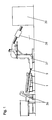
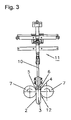
- Fig. 2 shows a side view of a liftable height guide 10 in a singulator 1, and Fig. 3 a view with a view in the conveying direction 42.
- This lift-off height guide 10 is arranged in front of the outlet end 40 of the singulator 1.
- the singling device 1 has a per se known roller conveyor 41 with two parallel rollers 7.
- the height guide 10 is attached to a lifting device 11 and by operation of lifting cylinders 20 which are pivotally connected to the height guide 10, can be raised.
- the height guide 10 is arranged above a conveyor track 16, in which the preforms 2 are conveyed in a single row 8.
- the single row 8 is formed in a known manner in a gap 12 between two counter-rotating rollers or rollers 7.
- the preforms 2 have a substantially cylindrical shape, with an end region 4 with a collar 5 and a threaded connector 6 at a first end, and a cylinder part 3 at the second end.
- the cylinder part 3 has a smaller diameter than the collar 5, so that the preform 2 is caught between the guide rollers 7 on the collar 5.
- the single row 8 is conveyed under the height guide 10 through to a drain rail 9.
- a first light barrier 14 is arranged with a first reflector 32 so that it responds when one or more of the preforms 2 are in this area of the conveyor track 16.
- a second light barrier 15 is arranged with a second reflector 33, which responds when one or more of the preforms 2 are in this area of the conveyor track 16.
- a jamming detection device 13 detects the state of the two light barriers via signal connections (not shown) and controls it accordingly via (not shown) further control connections to the lifting cylinder 20 for lifting the height guide 10 at.
- the jammed preforms 2 separate from each other and from the height guide 10 and slip through the sequence 9.
- the detachment of the preforms 2 from each other and the slipping their collar 5 together is facilitated by the fact that the preforms 2 are accelerated on the increasingly inclined flow 9 and no Preforms 2 are in the process 9, which slow this movement and separation of the preforms 2.
- the height guide 10 is raised for about half to one and a half seconds, typically about one second, and then lowered again.
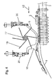
- Fig. 4 shows a view of such a height guide 10 in combination with a scrubstaurad or Kickerrad 17.
- the grillstaurad 17 has paddles or blades 18, which are each provided with a slot-like recess 19, in which the height guide 10 extends.
- the tips of the blades 18 preferably extend at least as deep as the height guide 10 at its lowest point, in a range (seen in the conveying direction) in front of the height guide the tips protrude further beyond the height guide 10 out.
- the backstay wheel 17 thus detects excessively protruding preforms 2 which protrude into the area of the blades 18 or which lie on top of one another and throws them back again to the rear.
- Preforms 2 which are not detected by the backwater 17, can still lead to a jamming with the height guide 10, which is fixed as described by raising the height guide 10.
- the height guide 10 and the remindurad 17 may be adjustable together or individually by itself in height, whereby an adaptation to different geometries of the preforms 2 is possible.
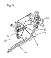
- Fig. 5 shows a perspective view of the mutual arrangement of height guide 10 and backstay 17, in which the recesses 19 and the course of the height guide 10 in the recesses 19 of the rotating blades 18 can be seen.
- the recesses 19 are deep enough so that even with raised height guide 10, this does not collide with the blades 18.
- the remindurad 17 is raised briefly together with the height guide 10.
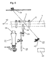
- Fig. 6 shows a side view of a first ejection device 21 in a roller conveyor.
- This ejection device 21 is arranged in the described example, in the conveying direction 42, in front of the height guide 10.
- the ejection device 21 has an ejection means 26, in this case a vertically movable body, which is vertically movable from underneath between the guide rollers 7 and pushes in such a movement located between the guide rollers 7 and incorrectly positioned preform 2 upwards.
- the ejection device 21 also has a detection device in the form of a parallel position detection device 22, which is set up to evaluate signals from a presence detector 23 and a position detector 24.
- the presence detector 23 determines whether a preform 2 is present at a predetermined measuring point of the roller conveyor 41 or the conveyor track 16.
- the presence detector 23 is for example a light barrier 43 with a reflector 34, which are arranged so that the light beam is passed through the gap 12 between the rollers 7 of the conveyor track 16 and responds when a preform 2 is present at the measuring point.
- the position detector 24 determines at the same time whether this preform 2 also hangs vertically.
- it preferably has an ultrasonic sensor 25 on, which determines a distance to the expected lower end of a preform 2 at the measuring point.
- a detection area 44, in which the ultrasonic sensor 25 responds, is shown schematically in the figure.
- the parallel position detection device 22 if this distance is too large and at the same time the presence detector 23 reports the presence of a preform 2, automatically triggers an actuation of the ejection means 26 and thereby the ejection of the misplaced preform 2.
- the location where the parallel position is controlled is upstream of the location where the ejection means 26 operates. Therefore, a delay is switched on between the time of detection of a wrong respectively horizontal preform 2 and the time of ejection. This depends on the conveying speed (depending on the size of the preforms, for example, about 15,000 to 80,000 pieces / hour) and is for example about half a second.
- the functions of the parallel position detection device 22 described herein may also be integrated into an optoelectronic sensor system having an optical image sensor 48 as shown in FIG Fig. 10 is suggested as an alternative.
- Such optoelectronic sensor systems are known per se in conveyor systems with pattern recognition.
- the ejection means 26 may comprise an asymmetrically designed ejector plunger 26 which pushes the preform 2 laterally or rearwardly in a preferred direction.
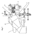
- a second ejection device with a blow-out device 27 (see Fig. 7 ), which is activated together with the ejection means 26 and the preform 2 blows away laterally.
- Fig. 7 shows a perspective view of the ejection device 21 during ejection of a conveyed body or preform 2 and a possible position of the optional blow-out device 27.
- the blow-off device 27 opposite a collecting device 45 is located. This begins the blown-off preforms 2, which are then returned to the beginning of the singulator 1.
- Fig. 8 shows a view of a pad detection device 28 with a blower 31 for removing horizontally and / or obliquely lying preforms.
- Fig. 9 shows a view of this arrangement from below.
- the support detection device 28 has a light barrier 29 with a reflector 35.
- the beam 30 of the light barrier 29 runs a little above the correct position of the preforms 2, so that it does not respond when the aligned preform 2 lie at the normal height between the guide rollers 7. If one or more of the preforms 2 lie as shown on the aligned preforms 2, they interrupt the beam 30.
- the support detection device 28 automatically triggers an air blast through the blower 31, which blows away the preforms 2 laterally.
- a plurality of air nozzles 46 distributed along the conveying direction 42 are present as part of the blow-out device 31, so that the preforms 2 are reliably detected by the air blast.
- two light barriers 29, in each case with associated air nozzles 46 are also arranged one after the other in the conveying direction 42. If, after blowing out, preforms 2 still rest on the basis of the signal of the first light barrier 29, they are detected by the second light barrier 29. This further increases the reliability of the system.
- an optical image sensor 48 see Fig. 10
- the support detection is also integrated into the system of pattern recognition and the visual barriers can then be at least partially eliminated.
- the ejection device 21 with the ejection means 26 and the support-detecting device 28 with the blow-out device 31 can be realized separately.
- the blow-out device 27 of the ejection device 21 is identical to the blow-out device 31 of the bearing-detection device 28.
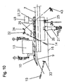
- Fig. 10 shows a side view of an embodiment of the invention with both the liftable height guide 10, and the ejector 21 and the In this illustration, the height guide 10 with the kicker 17, the ejector 21 with the associated blower 27 and the blower 31 are arranged at a preferred position along the conveyor track 16.
- the illustration also shows schematically the arrangement and orientation of the light barriers 15, 14 and 43 as well as of the ultrasonic sensor 25.
- the preforms 2 are conveyed in the conveying direction 42 through these components to the run-off rail 9. All preforms 2, which are wrong and / or disturbing, are removed or brought into a correct position by the combination of these components before the drain rail 9 from the conveyor track 16.
- Fig. 10 shows a side view of an embodiment of the invention with both the liftable height guide 10, and the ejector 21 and the In this illustration, the height guide 10 with the kicker 17, the ejector 21 with the associated blower 27 and the blower 31 are arranged at a preferred position along the conveyor track 16.
- the illustration also
- a detection device in the form of an optoelectronic sensor or an optical image sensor 48 for pattern recognition.
- This image sensor 48 comprises an optics, an image recorder and a processor and a control device for controlling the first ejection device 21 and / or the second ejection device with the blow-out device 27, 31.
- the optoelectronic image sensor 48 the light barriers 43, 29 and the ultrasonic sensor 25 omitted, since the functions of these sensors are taken over by the image sensor 48. However, they can also be used, at least partially, to improve the safety of the overall system.
Landscapes
- Engineering & Computer Science (AREA)
- Mechanical Engineering (AREA)
- Manufacturing & Machinery (AREA)
- Attitude Control For Articles On Conveyors (AREA)
- Blow-Moulding Or Thermoforming Of Plastics Or The Like (AREA)
- Sorting Of Articles (AREA)
- Feeding Of Articles To Conveyors (AREA)
- Processing And Handling Of Plastics And Other Materials For Molding In General (AREA)
- Control Of Conveyors (AREA)
- Extrusion Moulding Of Plastics Or The Like (AREA)
- Branching, Merging, And Special Transfer Between Conveyors (AREA)
Claims (22)
- Dispositif séparateur (1) pour corps cylindriques (2), tels que des ébauches ou préformes pour corps creux, qui présentent, à une première extrémité, au moins une collerette (5), et, à une deuxième extrémité, un diamètre qui est inférieur au diamètre de la collerette (5), le dispositif séparateur (1) présentant une paire d'éléments de guidage (7) agencés de manière mutuellement parallèle, entre lesquels les corps cylindriques (2) peuvent être redressés, à savoir que les corps cylindriques (2) sont suspendus chacun par la collerette (5) aux éléments de guidage (7) et les corps cylindriques (2) forment une rangée individuelle (8) le long des éléments de guidage (7) et peuvent ainsi être menés vers une sortie (9) pour la poursuite du convoyage ou du transport des corps cylindriques (2), le dispositif séparateur comprenant un dispositif de détection qui détecte des ébauches ou préformes (2) positionnées de manière incorrecte et/ou imbriquées, et est équipé d'un dispositif de commande pour des dispositifs d'éjection, caractérisé en ce que le dispositif de détection est agencé dans la zone des éléments de guidage (7), et dans la zones des éléments de guidage (7) sont agencés un premier dispositif d'éjection (21) comprenant un moyen d'éjection (26) s'engageant du bas, entre les éléments de guidage (7), pour l'éjection d'ébauches ou de préformes (2), et un deuxième dispositif d'éjection comprenant un dispositif de soufflage (27, 31) pour éjecter des ébauches ou préformes (2) en les évacuant des éléments de guidage (7) par soufflage.
- Dispositif séparateur (1) selon la revendication 1, caractérisé en ce que le dispositif de détection est un détecteur optoélectronique, qui comprend une optique, un système de prise de vues et un processeur, et ce détecteur optoélectronique, vu dans la direction de transport ou de convoyage des ébauches ou préformes (2), est agencé, avec les moyens d'éjection (21, 27, 31), dans la zone du début du parcours partiel des éléments de guidage (7).
- Dispositif séparateur (1) selon la revendication 2, caractérisé en ce que le détecteur optoélectronique est équipé de moyens de comparaison, qui engendrent, au moyen d'un processeur, un signal de commande pour au moins l'un des moyens d'éjection (21, 27, 31), lorsqu'une ébauche ou préforme (2) repose de manière incorrecte sur les éléments de guidage (7) ou que deux ébauches ou préformes (2) ou davantage sont imbriquées les unes avec les autres.
- Dispositif séparateur (1) selon la revendication 1, caractérisé en ce que le dispositif de détection présente un dispositif de détection de position parallèle (22) avec un détecteur de présence (23) et un détecteur de position (24), le détecteur de présence (23) déterminant la présence d'un corps cylindrique (2) entre les éléments de guidage (7) et le détecteur de position (24) déterminant l'orientation du corps cylindrique (2), et en ce que le dispositif de détection de position parallèle (22) déclenche, en cas de présence d'un corps cylindrique (2), qui présente une orientation incorrecte, l'éjection du corps cylindrique (2).
- Dispositif séparateur (1) selon la revendication 4, caractérisé en ce que le détecteur de présence (23) est une barrière photoélectrique, et en particulier le rayon lumineux de la barrière photoélectrique (23) mène du haut vers le bas ou inversement à travers la rangée individuelle (8) des corps cylindriques (2).
- Dispositif séparateur (1) selon la revendication 4 ou la revendication 5, caractérisé en ce que le détecteur de position (24) détecte une présence des deuxièmes extrémités (3) des corps cylindriques (2), dans une zone sous les éléments de guidage (7).
- Dispositif séparateur (1) selon l'une des revendications 4 à 6, caractérisé en ce que le détecteur de position (24) comprend un détecteur à ultrasons (25), qui mesure la distance du détecteur à ultrasons (25) à la position attendue des deuxièmes extrémités (3) des corps cylindriques (2), et, dans le cas où cette distance dépasse une valeur prédéterminée, le détecteur de position (24) signale une orientation incorrecte du corps cylindrique (2) correspondant.
- Dispositif séparateur (1) selon l'une des revendications 1 à 7, caractérisé en ce que le premier dispositif d'éjection (21) comprend un moyen d'éjection mobile (26), qui, pour l'éjection d'un corps cylindrique (2) d'orientation incorrecte, se déplace à partir du bas, entre les éléments de guidage (7), en soulevant ainsi ce corps cylindrique (2) et en l'éjectant.
- Dispositif séparateur (1) selon l'une des revendications 1 à 8, caractérisé en ce que le deuxième dispositif d'éjection comprend un dispositif de soufflage (27) associé, pour l'évacuation latérale par soufflage après le soulèvement d'un corps cylindrique (2).
- Dispositif séparateur (1) selon l'une des revendications précédentes, caractérisé en ce que le dispositif séparateur (1) comprend par ailleurs un dispositif de détection de superposition (28), qui détecte si un corps cylindrique (2) repose sur les corps cylindriques (2) transportés ou convoyés dans la rangée individuelle (8), et, si cela est le cas, active un dispositif de soufflage (31) associé, pour l'évacuation latérale par soufflage d'un corps cylindrique (2), en le dégageant des éléments de guidage (7) respectivement de la rangée individuelle (8).
- Dispositif séparateur (1) selon la revendication 10, caractérisé en ce que le dispositif de détection de superposition (28) comprend une barrière photoélectrique (29) dont le rayon (30) s'étend horizontalement et en formant un angle par rapport au parcours des éléments de guidage (7) respectivement de la rangée individuelle (8), et dont la hauteur est réglée de façon telle que la barrière photoélectrique (28) déclenche dans le cas de corps cylindriques (2) superposés.
- Dispositif séparateur (1) selon la revendication 10 ou la revendication 11, en relation avec la revendication 9, caractérisé en ce que le dispositif de soufflage (27), qui est associé au deuxième dispositif d'éjection, est identique au dispositif de soufflage (31), qui est associé au dispositif de détection de superposition (28).
- Dispositif séparateur (1) selon l'une des revendications précédentes, caractérisé en ce que le dispositif séparateur (1) comprend un guidage de hauteur (10) agencé au-dessus de la rangée individuelle (8), une distance entre le guidage de hauteur (10) et les corps cylindriques (2), vu dans la direction de transport ou de convoyage, se réduisant jusqu'à une distance prédéterminée par rapport aux éléments de guidage (7), ce qui fait que des corps cylindriques (2) dépassant verticalement, lorsqu'ils sont transportés dans la direction de transport, sont repoussés vers le bas par le dispositif de guidage de hauteur (10), et le dispositif de guidage de hauteur (10) peut être soulevé brièvement au moyen d'un dispositif de levage (11) conformément à un signal de déclenchement.
- Dispositif séparateur (1) selon la revendication 13, caractérisé en ce que les éléments de guidage (7) sont des rouleaux, notamment en rotation opposée, et les corps cylindriques (2) sont transportés dans un espace intermédiaire (12) entre les rouleaux (7).
- Dispositif séparateur (1) selon la revendication 13 ou la revendication 14, caractérisé en ce que le dispositif séparateur (1) comprend un dispositif de détection de coincement (13), qui est conçu pour détecter un blocage d'un ou de plusieurs corps cylindriques (2) contre le guidage de hauteur (10), et engendrer alors le signal de déclenchement pour soulever le guidage de hauteur (10).
- Dispositif séparateur (1) selon la revendication 15, caractérisé en ce que le dispositif de détection de coincement (13) est conçu pour détecter si des corps cylindriques (2) sont, en se référant à la direction de transport, bloqués devant le guidage de hauteur (10) et si dans une zone après le guidage de hauteur (10), il n'y a pas de corps cylindriques (2) présents, et engendrer le signal de déclenchement lorsque ces deux conditions sont remplies.
- Dispositif séparateur (1) selon la revendication 15 ou la revendication 16, caractérisé en ce que le dispositif de détection de coincement (13) comporte un premier détecteur de présence, notamment une première barrière photoélectrique (14), qui détecte la présence de corps cylindriques (2) dans une zone d'une voie de transport ou de convoyage (16) des corps cylindriques (2), située devant le guidage de hauteur (10), ainsi qu'un deuxième détecteur de présence, notamment une deuxième barrière photoélectrique (15), qui détecte la présence de corps cylindriques (2) dans une zone de la voie de transport (16) des corps cylindriques (2) située après le guidage de hauteur (10).
- Dispositif séparateur (1) selon la revendication 17, caractérisé en ce que l'un ou les deux détecteurs de présence est une barrière photoélectrique ou respectivement sont des barrières photoélectriques (14), (15), et sont agencés chacun par rapport à la voie de transport (16) de manière telle, que le rayon de la barrière photoélectrique (14), (15), lorsque les corps cylindriques (2) se succèdent directement sur la voie de transport (16), passe respectivement par plusieurs des corps cylindriques (2).
- Dispositif séparateur (1) selon l'une des revendications 13 à 18, caractérisé en ce que le guidage de hauteur (10) est agencé dans la zone d'une roue de retenue (17), et des aubes (18) de la roue de retenue (17) présentent chacune une encoche (19) qui correspond à la forme du guidage de hauteur (10), et les aubes (18) dépassent du guidage de hauteur (10) vers le bas, au moins dans une zone dans laquelle le guidage de hauteur (10) n'est pas encore actif.
- Procédé pour séparer des corps cylindriques (2), par exemple des ébauches ou préformes pour corps creux, qui présentent, à une première extrémité, au moins une collerette (5), et, à une deuxième extrémité, un diamètre qui est inférieur au diamètre de la collerette (5), les corps cylindriques (2) pouvant être redressés entre une paire d'éléments de guidage (7) agencés de manière mutuellement parallèle, à savoir que les corps cylindriques (2) sont suspendus chacun par la collerette (5) aux éléments de guidage (7) et les corps cylindriques (2) forment une rangée individuelle (8) le long des éléments de guidage (7) et sont ainsi menés vers une sortie (9) pour la poursuite du transport ou du convoyage des corps cylindriques (2), le procédé étant tel qu'avant le transfert des corps cylindriques (2) à la sortie (9), dans la zone des éléments de guidage (7), on effectue une détection de présence et simultanément une détection de position, et on détermine si un corps cylindrique (2) est certes présent en un endroit prédéterminé le long des éléments de guidage, mais n'est pas suspendu à la collerette (5), vers le bas, ou si deux corps cylindriques (2) ou davantage sont mutuellement imbriqués les uns avec les autres, et si cela est le cas, le corps cylindrique (2) est repoussé du bas vers le haut, hors de la rangée individuelle (8), par des moyens d'éjection s'engageant entre les éléments de guidage, et est évacué par soufflage à l'aide d'un dispositif de soufflage.
- Procédé selon la revendication 20, caractérisé en ce que les corps cylindriques (2) sont transportés ou convoyés sous un guidage de hauteur (10) agencé au-dessus de la rangée individuelle (8), une distance entre le guidage de hauteur (10) et les corps cylindriques (2), vu dans la direction de transport ou de convoyage, se réduisant jusqu'à une distance prédéterminée des éléments de guidage (7), ce qui fait que des corps cylindriques (2) dépassant verticalement, lorsqu'ils sont transportés dans la direction de transport, sont repoussés vers le bas par le dispositif de guidage de hauteur (10), et le dispositif de guidage de hauteur (10) pouvant être soulevé brièvement au moyen d'un dispositif de levage (11) conformément à un signal de déclenchement.
- Procédé selon la revendication 20 ou la revendication 21, caractérisé en ce que dans la zone des éléments de guidage (7), on détermine en plus si un corps cylindrique (2) repose sur les corps cylindriques (2) transportés ou convoyés dans la rangée individuelle (8), et, si cela est le cas, le corps cylindrique (2) est évacué par soufflage en le dégageant des éléments de guidage (7) respectivement de la rangée individuelle (8), et à cet effet, on émet un signal de détection et on engendre un jet d'air au-dessus des éléments de guidage (7) et environ perpendiculairement à la direction de transport des corps cylindriques (2), lorsqu'un corps (2) en position incorrecte est détecté.
Applications Claiming Priority (2)
| Application Number | Priority Date | Filing Date | Title |
|---|---|---|---|
| CH01110/08A CH699223A1 (de) | 2008-07-17 | 2008-07-17 | Vorrichtung und Verfahren zum Vereinzeln von zylindrischen Körpern. |
| PCT/CH2009/000256 WO2010006462A1 (fr) | 2008-07-17 | 2009-07-15 | Dispositif et procédé pour séparer des corps cylindriques |
Publications (2)
| Publication Number | Publication Date |
|---|---|
| EP2303733A1 EP2303733A1 (fr) | 2011-04-06 |
| EP2303733B1 true EP2303733B1 (fr) | 2012-01-04 |
Family
ID=40303713
Family Applications (1)
| Application Number | Title | Priority Date | Filing Date |
|---|---|---|---|
| EP09797340A Active EP2303733B1 (fr) | 2008-07-17 | 2009-07-15 | Dispositif et procédé pour séparer des corps cylindriques |
Country Status (6)
| Country | Link |
|---|---|
| US (1) | US8522956B2 (fr) |
| EP (1) | EP2303733B1 (fr) |
| CN (1) | CN102099269B (fr) |
| AT (1) | ATE539986T1 (fr) |
| CH (1) | CH699223A1 (fr) |
| WO (1) | WO2010006462A1 (fr) |
Cited By (2)
| Publication number | Priority date | Publication date | Assignee | Title |
|---|---|---|---|---|
| EP2650101A1 (fr) * | 2012-04-10 | 2013-10-16 | Krones AG | Convoyeur à rouleaux pour préformes en matière plastique |
| DE102012011762A1 (de) * | 2012-06-15 | 2013-12-19 | Khs Corpoplast Gmbh | Vereinzelungsvorrichtung für Vorformlinge mit einer Einrichtung zum Aussondern von falsch positionierten Vorformlingen |
Families Citing this family (21)
| Publication number | Priority date | Publication date | Assignee | Title |
|---|---|---|---|---|
| CH699222A1 (de) * | 2008-07-17 | 2010-01-29 | M Tanner Ag | Vorrichtung und Verfahren zum Vereinzeln von zylindrischen Körpern. |
| CH702406A1 (de) * | 2009-12-11 | 2011-06-15 | M Tanner Ag | Vorrichtung zum Aussortieren von falsch positionierten zylindrischen Körpern in einer Vereinzelungs- und Fördereinrichtung. |
| DE102010008367A1 (de) * | 2010-02-17 | 2011-08-18 | Krones Ag, 93073 | Rollensortiereinrichtung und Sortierverfahren zum Sortieren von Vorformlingen sowie Transportvorrichtung mit solcher Rollensortiereinrichtung |
| CH704401A1 (de) * | 2011-01-28 | 2012-07-31 | M Tanner Ag | Fördereinrichtung für zylindrische Körper, mit in Förderrichtung geneigten Ablaufschienen. |
| DE102011016858B4 (de) | 2011-04-13 | 2026-03-26 | Krones Aktiengesellschaft | Vorrichtung und Verfahren zum Transportieren von Kunststoffvorformlingen |
| DE102012101653A1 (de) * | 2012-02-29 | 2013-08-29 | Krones Ag | Preformtransport mit individueller Auswurfmöglichkeit |
| DE102012017699A1 (de) * | 2012-09-07 | 2014-03-13 | Khs Corpoplast Gmbh | Vereinzelungsvorrichtung für Vorformlinge |
| US9533833B2 (en) * | 2013-08-08 | 2017-01-03 | Norwalt Design, Inc. | Unjamming system for product feeders |
| DE102014102203A1 (de) | 2014-02-20 | 2015-08-20 | Krones Ag | Verfahren zum Transportieren von Kunststoffvorformlingen, Vorrichtung zum Transportieren von Kunststoffvorformlingen und Schaltungsanordnung für eine derartige Vorrichtung |
| EP3157729B1 (fr) * | 2014-06-18 | 2018-08-01 | Sacmi Imola S.C. | Système de convoyage des préforms |
| DE102014010862B4 (de) * | 2014-07-25 | 2021-01-07 | Khs Corpoplast Gmbh | Verfahren und Vorrichtung zum Transport von Vorformlingen |
| DE102015205984A1 (de) * | 2015-04-02 | 2016-10-06 | Krones Aktiengesellschaft | Verfahren und Führungssystem für den Transport von Behältern oder Behälter-komponenten in Industrieanlagen für die Behälterherstellung und/oder Produktabfüllung |
| DE102015215366A1 (de) * | 2015-08-12 | 2017-02-16 | Robert Bosch Gmbh | Vorrichtung und Verfahren zum Zuführen von Produkten |
| CH711442A1 (de) * | 2015-08-21 | 2017-02-28 | M Tanner Ag | Vorrichtung zum Ruhigstellen von Vorformlingen für Kunststoffbehälter. |
| EP3239077A1 (fr) | 2016-04-29 | 2017-11-01 | M. Tanner AG | Dispositif d'approvisionnement d'une installation de transformation en objets utilises comme produits en vrac |
| FR3051780A1 (fr) * | 2016-05-25 | 2017-12-01 | Sidel Participations | Procede de deblocage du defilement de corps creux dans un convoyeur a glissiere |
| IT201600128336A1 (it) * | 2016-12-19 | 2018-06-19 | True Keg S R L | Un sistema per l’alimentazione di preforme in materiale polimerico ad una macchina di stirosoffiaggio |
| EP4007884B1 (fr) * | 2019-08-01 | 2025-02-19 | MGS Machine Corporation | Machine automatisée pour l'organisation et l'alimentation de produits cylindriques |
| DE102022114820A1 (de) * | 2022-06-13 | 2023-12-14 | Krones Aktiengesellschaft | Rollensortierer DirectLink |
| DE102022117742A1 (de) * | 2022-07-15 | 2024-01-18 | Krones Aktiengesellschaft | Vorrichtung und Verfahren zum Umformen von Kunststoffvorformlingen zu Kunststoffbehältnissen mit Wechselroboter |
| DE102023109658A1 (de) * | 2023-04-18 | 2024-10-24 | Krones Aktiengesellschaft | Vorrichtung und Verfahren zum Transportieren von Kunststoffvorformlingen mit Störungsbeseitigung |
Family Cites Families (10)
| Publication number | Priority date | Publication date | Assignee | Title |
|---|---|---|---|---|
| US3506840A (en) * | 1967-09-08 | 1970-04-14 | Anchor Hocking Glass Corp | Down-ware rejector system |
| US4223778A (en) * | 1978-05-12 | 1980-09-23 | Owens-Illinois, Inc. | Parison handling assemblies and methods for handling parisons |
| US4440286A (en) * | 1981-03-13 | 1984-04-03 | Avdel Limited | Orientating device |
| FR2556273B1 (fr) * | 1983-12-09 | 1986-07-25 | Pont A Mousson | Procede de fabrication de bouteilles en matiere plastique a partir d'ebauches et ebauche obtenue a partir de ce procede |
| JP2991000B2 (ja) * | 1993-04-22 | 1999-12-13 | 神鋼電機株式会社 | 部品整送装置 |
| JPH09156751A (ja) * | 1995-12-06 | 1997-06-17 | Ykk Corp | 部品整送フィーダ |
| IT1305277B1 (it) * | 1998-10-20 | 2001-04-19 | Sipa Spa | Dispositivo di individuazione e di eliminazione di preformeagganciate da una linea di trasferimento continuo. |
| FR2816297B1 (fr) | 2000-11-03 | 2003-01-10 | Sidel Sa | Systeme d'alimentation de preformes destine notamment a une machine de soufflage de recipients |
| FR2864050B1 (fr) * | 2003-12-23 | 2007-04-06 | Sidel Sa | Systeme d'alimentation de preformes comportant un dispositif d'elimination selective des preformes mal positionnees de type allonge |
| US7322458B1 (en) * | 2006-08-02 | 2008-01-29 | Norwalt Design Inc. | Orienting and feeding apparatus for manufacturing line |
-
2008
- 2008-07-17 CH CH01110/08A patent/CH699223A1/de not_active Application Discontinuation
-
2009
- 2009-07-15 CN CN200980128043.5A patent/CN102099269B/zh not_active Expired - Fee Related
- 2009-07-15 US US13/002,754 patent/US8522956B2/en active Active
- 2009-07-15 EP EP09797340A patent/EP2303733B1/fr active Active
- 2009-07-15 WO PCT/CH2009/000256 patent/WO2010006462A1/fr not_active Ceased
- 2009-07-15 AT AT09797340T patent/ATE539986T1/de active
Cited By (2)
| Publication number | Priority date | Publication date | Assignee | Title |
|---|---|---|---|---|
| EP2650101A1 (fr) * | 2012-04-10 | 2013-10-16 | Krones AG | Convoyeur à rouleaux pour préformes en matière plastique |
| DE102012011762A1 (de) * | 2012-06-15 | 2013-12-19 | Khs Corpoplast Gmbh | Vereinzelungsvorrichtung für Vorformlinge mit einer Einrichtung zum Aussondern von falsch positionierten Vorformlingen |
Also Published As
| Publication number | Publication date |
|---|---|
| US20110120833A1 (en) | 2011-05-26 |
| CN102099269B (zh) | 2014-08-13 |
| CN102099269A (zh) | 2011-06-15 |
| ATE539986T1 (de) | 2012-01-15 |
| WO2010006462A1 (fr) | 2010-01-21 |
| US8522956B2 (en) | 2013-09-03 |
| CH699223A1 (de) | 2010-01-29 |
| EP2303733A1 (fr) | 2011-04-06 |
Similar Documents
| Publication | Publication Date | Title |
|---|---|---|
| EP2303733B1 (fr) | Dispositif et procédé pour séparer des corps cylindriques | |
| EP2303732B1 (fr) | Dispositif et procédé pour séparer des corps cylindriques | |
| EP2509894B1 (fr) | Dispositif pour trier et éliminer des corps cylindriques mal positionnés dans un dispositif de séparation et de transport | |
| EP2845715B1 (fr) | Unité d'éjecteur et d'inspection | |
| EP2765558A1 (fr) | Dispositif de séparation de pièces de monnaie | |
| WO2012163978A2 (fr) | Procédé et dispositif permettant le transport d'objets vers une station | |
| EP0996531B1 (fr) | Procede et dispositif pour produire des corps creux en matiere plastique | |
| DE102016101027B4 (de) | Rundläufertablettenpresse | |
| EP0699396B1 (fr) | Dispositif pour le transport des barette de filtres | |
| DE102009003844B4 (de) | Vorrichtung und Verfahren zum Ausleiten von Objekten von einer sich bewegenden Transporteinrichtung | |
| EP2295156A2 (fr) | Dispositif de transport avec moyens de détection d'articles renversés et son procédé de commande | |
| DE102020134010B3 (de) | Freies glasverpacken | |
| EP4601976A1 (fr) | Dispositif de transport et de séparation de pièces | |
| EP3453648A1 (fr) | Dispositif d'alimentation | |
| EP3028963A1 (fr) | Procede d'orientation d'un recipient | |
| EP3453651B1 (fr) | Unité de transport et d'alimentation pour préformes | |
| EP4269288A2 (fr) | Dispositif de transport et procédé de transport d'applicateurs de tampon | |
| EP3199333B1 (fr) | Presse rotative pour comprimés | |
| EP4520691A1 (fr) | Dispositif de séparation, agencement de soufflage et procédé de fonctionnement | |
| DE102011016858A1 (de) | Vorrichtung und Verfahren zum Transportieren von Kunststoffvorformlingen | |
| DE202019106352U1 (de) | Sternradeinheit | |
| DE3211543C2 (de) | Behandlungsmaschine für Gegenstände, insbesondere Füll- oder Etikettiermaschine für Flaschen | |
| DE3914360C2 (fr) | ||
| EP3571146B1 (fr) | Procédé de tri pour corps creux et dispositif de tri | |
| EP4339136A1 (fr) | Dispositif de séparation ainsi que procédé de séparation de préformes |
Legal Events
| Date | Code | Title | Description |
|---|---|---|---|
| PUAI | Public reference made under article 153(3) epc to a published international application that has entered the european phase |
Free format text: ORIGINAL CODE: 0009012 |
|
| 17P | Request for examination filed |
Effective date: 20101221 |
|
| AK | Designated contracting states |
Kind code of ref document: A1 Designated state(s): AT BE BG CH CY CZ DE DK EE ES FI FR GB GR HR HU IE IS IT LI LT LU LV MC MK MT NL NO PL PT RO SE SI SK SM TR |
|
| AX | Request for extension of the european patent |
Extension state: AL BA RS |
|
| GRAP | Despatch of communication of intention to grant a patent |
Free format text: ORIGINAL CODE: EPIDOSNIGR1 |
|
| DAX | Request for extension of the european patent (deleted) | ||
| GRAS | Grant fee paid |
Free format text: ORIGINAL CODE: EPIDOSNIGR3 |
|
| GRAA | (expected) grant |
Free format text: ORIGINAL CODE: 0009210 |
|
| AK | Designated contracting states |
Kind code of ref document: B1 Designated state(s): AT BE BG CH CY CZ DE DK EE ES FI FR GB GR HR HU IE IS IT LI LT LU LV MC MK MT NL NO PL PT RO SE SI SK SM TR |
|
| REG | Reference to a national code |
Ref country code: GB Ref legal event code: FG4D Free format text: NOT ENGLISH |
|
| REG | Reference to a national code |
Ref country code: CH Ref legal event code: EP |
|
| REG | Reference to a national code |
Ref country code: AT Ref legal event code: REF Ref document number: 539986 Country of ref document: AT Kind code of ref document: T Effective date: 20120115 |
|
| REG | Reference to a national code |
Ref country code: IE Ref legal event code: FG4D |
|
| REG | Reference to a national code |
Ref country code: CH Ref legal event code: NV Representative=s name: FREI PATENTANWALTSBUERO AG |
|
| REG | Reference to a national code |
Ref country code: DE Ref legal event code: R096 Ref document number: 502009002437 Country of ref document: DE Effective date: 20120308 |
|
| REG | Reference to a national code |
Ref country code: NL Ref legal event code: VDEP Effective date: 20120104 |
|
| PG25 | Lapsed in a contracting state [announced via postgrant information from national office to epo] |
Ref country code: SI Free format text: LAPSE BECAUSE OF FAILURE TO SUBMIT A TRANSLATION OF THE DESCRIPTION OR TO PAY THE FEE WITHIN THE PRESCRIBED TIME-LIMIT Effective date: 20120104 |
|
| REG | Reference to a national code |
Ref country code: CH Ref legal event code: NV Representative=s name: PATENTANWAELTE SCHAAD, BALASS, MENZL & PARTNER AG |
|
| LTIE | Lt: invalidation of european patent or patent extension |
Effective date: 20120104 |
|
| PG25 | Lapsed in a contracting state [announced via postgrant information from national office to epo] |
Ref country code: NO Free format text: LAPSE BECAUSE OF FAILURE TO SUBMIT A TRANSLATION OF THE DESCRIPTION OR TO PAY THE FEE WITHIN THE PRESCRIBED TIME-LIMIT Effective date: 20120404 Ref country code: HR Free format text: LAPSE BECAUSE OF FAILURE TO SUBMIT A TRANSLATION OF THE DESCRIPTION OR TO PAY THE FEE WITHIN THE PRESCRIBED TIME-LIMIT Effective date: 20120104 Ref country code: NL Free format text: LAPSE BECAUSE OF FAILURE TO SUBMIT A TRANSLATION OF THE DESCRIPTION OR TO PAY THE FEE WITHIN THE PRESCRIBED TIME-LIMIT Effective date: 20120104 Ref country code: IS Free format text: LAPSE BECAUSE OF FAILURE TO SUBMIT A TRANSLATION OF THE DESCRIPTION OR TO PAY THE FEE WITHIN THE PRESCRIBED TIME-LIMIT Effective date: 20120504 Ref country code: BG Free format text: LAPSE BECAUSE OF FAILURE TO SUBMIT A TRANSLATION OF THE DESCRIPTION OR TO PAY THE FEE WITHIN THE PRESCRIBED TIME-LIMIT Effective date: 20120404 Ref country code: LT Free format text: LAPSE BECAUSE OF FAILURE TO SUBMIT A TRANSLATION OF THE DESCRIPTION OR TO PAY THE FEE WITHIN THE PRESCRIBED TIME-LIMIT Effective date: 20120104 |
|
| REG | Reference to a national code |
Ref country code: IE Ref legal event code: FD4D |
|
| PG25 | Lapsed in a contracting state [announced via postgrant information from national office to epo] |
Ref country code: PT Free format text: LAPSE BECAUSE OF FAILURE TO SUBMIT A TRANSLATION OF THE DESCRIPTION OR TO PAY THE FEE WITHIN THE PRESCRIBED TIME-LIMIT Effective date: 20120504 Ref country code: FI Free format text: LAPSE BECAUSE OF FAILURE TO SUBMIT A TRANSLATION OF THE DESCRIPTION OR TO PAY THE FEE WITHIN THE PRESCRIBED TIME-LIMIT Effective date: 20120104 Ref country code: GR Free format text: LAPSE BECAUSE OF FAILURE TO SUBMIT A TRANSLATION OF THE DESCRIPTION OR TO PAY THE FEE WITHIN THE PRESCRIBED TIME-LIMIT Effective date: 20120405 Ref country code: LV Free format text: LAPSE BECAUSE OF FAILURE TO SUBMIT A TRANSLATION OF THE DESCRIPTION OR TO PAY THE FEE WITHIN THE PRESCRIBED TIME-LIMIT Effective date: 20120104 Ref country code: PL Free format text: LAPSE BECAUSE OF FAILURE TO SUBMIT A TRANSLATION OF THE DESCRIPTION OR TO PAY THE FEE WITHIN THE PRESCRIBED TIME-LIMIT Effective date: 20120104 |
|
| PG25 | Lapsed in a contracting state [announced via postgrant information from national office to epo] |
Ref country code: CY Free format text: LAPSE BECAUSE OF FAILURE TO SUBMIT A TRANSLATION OF THE DESCRIPTION OR TO PAY THE FEE WITHIN THE PRESCRIBED TIME-LIMIT Effective date: 20120104 |
|
| PG25 | Lapsed in a contracting state [announced via postgrant information from national office to epo] |
Ref country code: DK Free format text: LAPSE BECAUSE OF FAILURE TO SUBMIT A TRANSLATION OF THE DESCRIPTION OR TO PAY THE FEE WITHIN THE PRESCRIBED TIME-LIMIT Effective date: 20120104 Ref country code: CZ Free format text: LAPSE BECAUSE OF FAILURE TO SUBMIT A TRANSLATION OF THE DESCRIPTION OR TO PAY THE FEE WITHIN THE PRESCRIBED TIME-LIMIT Effective date: 20120104 Ref country code: SE Free format text: LAPSE BECAUSE OF FAILURE TO SUBMIT A TRANSLATION OF THE DESCRIPTION OR TO PAY THE FEE WITHIN THE PRESCRIBED TIME-LIMIT Effective date: 20120104 Ref country code: EE Free format text: LAPSE BECAUSE OF FAILURE TO SUBMIT A TRANSLATION OF THE DESCRIPTION OR TO PAY THE FEE WITHIN THE PRESCRIBED TIME-LIMIT Effective date: 20120104 Ref country code: IE Free format text: LAPSE BECAUSE OF FAILURE TO SUBMIT A TRANSLATION OF THE DESCRIPTION OR TO PAY THE FEE WITHIN THE PRESCRIBED TIME-LIMIT Effective date: 20120104 Ref country code: RO Free format text: LAPSE BECAUSE OF FAILURE TO SUBMIT A TRANSLATION OF THE DESCRIPTION OR TO PAY THE FEE WITHIN THE PRESCRIBED TIME-LIMIT Effective date: 20120104 |
|
| PLBE | No opposition filed within time limit |
Free format text: ORIGINAL CODE: 0009261 |
|
| STAA | Information on the status of an ep patent application or granted ep patent |
Free format text: STATUS: NO OPPOSITION FILED WITHIN TIME LIMIT |
|
| PG25 | Lapsed in a contracting state [announced via postgrant information from national office to epo] |
Ref country code: SK Free format text: LAPSE BECAUSE OF FAILURE TO SUBMIT A TRANSLATION OF THE DESCRIPTION OR TO PAY THE FEE WITHIN THE PRESCRIBED TIME-LIMIT Effective date: 20120104 |
|
| 26N | No opposition filed |
Effective date: 20121005 |
|
| BERE | Be: lapsed |
Owner name: M. TANNER A.G. Effective date: 20120731 |
|
| REG | Reference to a national code |
Ref country code: DE Ref legal event code: R097 Ref document number: 502009002437 Country of ref document: DE Effective date: 20121005 |
|
| PG25 | Lapsed in a contracting state [announced via postgrant information from national office to epo] |
Ref country code: MC Free format text: LAPSE BECAUSE OF NON-PAYMENT OF DUE FEES Effective date: 20120731 Ref country code: MK Free format text: LAPSE BECAUSE OF FAILURE TO SUBMIT A TRANSLATION OF THE DESCRIPTION OR TO PAY THE FEE WITHIN THE PRESCRIBED TIME-LIMIT Effective date: 20120104 |
|
| PG25 | Lapsed in a contracting state [announced via postgrant information from national office to epo] |
Ref country code: ES Free format text: LAPSE BECAUSE OF FAILURE TO SUBMIT A TRANSLATION OF THE DESCRIPTION OR TO PAY THE FEE WITHIN THE PRESCRIBED TIME-LIMIT Effective date: 20120415 |
|
| PG25 | Lapsed in a contracting state [announced via postgrant information from national office to epo] |
Ref country code: BE Free format text: LAPSE BECAUSE OF NON-PAYMENT OF DUE FEES Effective date: 20120731 |
|
| PG25 | Lapsed in a contracting state [announced via postgrant information from national office to epo] |
Ref country code: MT Free format text: LAPSE BECAUSE OF FAILURE TO SUBMIT A TRANSLATION OF THE DESCRIPTION OR TO PAY THE FEE WITHIN THE PRESCRIBED TIME-LIMIT Effective date: 20120104 |
|
| PGFP | Annual fee paid to national office [announced via postgrant information from national office to epo] |
Ref country code: GB Payment date: 20130719 Year of fee payment: 5 |
|
| PG25 | Lapsed in a contracting state [announced via postgrant information from national office to epo] |
Ref country code: TR Free format text: LAPSE BECAUSE OF FAILURE TO SUBMIT A TRANSLATION OF THE DESCRIPTION OR TO PAY THE FEE WITHIN THE PRESCRIBED TIME-LIMIT Effective date: 20120104 |
|
| PG25 | Lapsed in a contracting state [announced via postgrant information from national office to epo] |
Ref country code: LU Free format text: LAPSE BECAUSE OF NON-PAYMENT OF DUE FEES Effective date: 20120715 Ref country code: SM Free format text: LAPSE BECAUSE OF FAILURE TO SUBMIT A TRANSLATION OF THE DESCRIPTION OR TO PAY THE FEE WITHIN THE PRESCRIBED TIME-LIMIT Effective date: 20120104 |
|
| PG25 | Lapsed in a contracting state [announced via postgrant information from national office to epo] |
Ref country code: HU Free format text: LAPSE BECAUSE OF FAILURE TO SUBMIT A TRANSLATION OF THE DESCRIPTION OR TO PAY THE FEE WITHIN THE PRESCRIBED TIME-LIMIT Effective date: 20090715 |
|
| GBPC | Gb: european patent ceased through non-payment of renewal fee |
Effective date: 20140715 |
|
| PG25 | Lapsed in a contracting state [announced via postgrant information from national office to epo] |
Ref country code: GB Free format text: LAPSE BECAUSE OF NON-PAYMENT OF DUE FEES Effective date: 20140715 |
|
| REG | Reference to a national code |
Ref country code: FR Ref legal event code: PLFP Year of fee payment: 8 |
|
| REG | Reference to a national code |
Ref country code: FR Ref legal event code: PLFP Year of fee payment: 9 |
|
| REG | Reference to a national code |
Ref country code: FR Ref legal event code: PLFP Year of fee payment: 10 |
|
| REG | Reference to a national code |
Ref country code: DE Ref legal event code: R081 Ref document number: 502009002437 Country of ref document: DE Owner name: M. TANNER AG, CH Free format text: FORMER OWNER: M. TANNER AG, ILLNAU, CH |
|
| PGFP | Annual fee paid to national office [announced via postgrant information from national office to epo] |
Ref country code: DE Payment date: 20250722 Year of fee payment: 17 |
|
| PGFP | Annual fee paid to national office [announced via postgrant information from national office to epo] |
Ref country code: IT Payment date: 20250724 Year of fee payment: 17 |
|
| PGFP | Annual fee paid to national office [announced via postgrant information from national office to epo] |
Ref country code: AT Payment date: 20250722 Year of fee payment: 17 Ref country code: FR Payment date: 20250725 Year of fee payment: 17 |
|
| PGFP | Annual fee paid to national office [announced via postgrant information from national office to epo] |
Ref country code: CH Payment date: 20250801 Year of fee payment: 17 |