EP2650596A2 - Lampe et connecteur à fiche - Google Patents
Lampe et connecteur à fiche Download PDFInfo
- Publication number
- EP2650596A2 EP2650596A2 EP13405044.2A EP13405044A EP2650596A2 EP 2650596 A2 EP2650596 A2 EP 2650596A2 EP 13405044 A EP13405044 A EP 13405044A EP 2650596 A2 EP2650596 A2 EP 2650596A2
- Authority
- EP
- European Patent Office
- Prior art keywords
- unit
- contacting
- base unit
- base
- luminaire
- Prior art date
- Legal status (The legal status is an assumption and is not a legal conclusion. Google has not performed a legal analysis and makes no representation as to the accuracy of the status listed.)
- Granted
Links
- 238000000034 method Methods 0.000 claims abstract description 7
- 238000006073 displacement reaction Methods 0.000 claims description 7
- 230000013011 mating Effects 0.000 claims description 2
- 238000005192 partition Methods 0.000 description 3
- 230000001771 impaired effect Effects 0.000 description 2
- 239000002184 metal Substances 0.000 description 2
- 241001295925 Gegenes Species 0.000 description 1
- 239000004020 conductor Substances 0.000 description 1
- 230000001419 dependent effect Effects 0.000 description 1
- 230000003993 interaction Effects 0.000 description 1
- 239000002932 luster Substances 0.000 description 1
- 230000001681 protective effect Effects 0.000 description 1
Images

Classifications
-
- F—MECHANICAL ENGINEERING; LIGHTING; HEATING; WEAPONS; BLASTING
- F21—LIGHTING
- F21S—NON-PORTABLE LIGHTING DEVICES; SYSTEMS THEREOF; VEHICLE LIGHTING DEVICES SPECIALLY ADAPTED FOR VEHICLE EXTERIORS
- F21S8/00—Lighting devices intended for fixed installation
- F21S8/03—Lighting devices intended for fixed installation of surface-mounted type
-
- F—MECHANICAL ENGINEERING; LIGHTING; HEATING; WEAPONS; BLASTING
- F21—LIGHTING
- F21V—FUNCTIONAL FEATURES OR DETAILS OF LIGHTING DEVICES OR SYSTEMS THEREOF; STRUCTURAL COMBINATIONS OF LIGHTING DEVICES WITH OTHER ARTICLES, NOT OTHERWISE PROVIDED FOR
- F21V23/00—Arrangement of electric circuit elements in or on lighting devices
- F21V23/06—Arrangement of electric circuit elements in or on lighting devices the elements being coupling devices, e.g. connectors
-
- H—ELECTRICITY
- H01—ELECTRIC ELEMENTS
- H01R—ELECTRICALLY-CONDUCTIVE CONNECTIONS; STRUCTURAL ASSOCIATIONS OF A PLURALITY OF MUTUALLY-INSULATED ELECTRICAL CONNECTING ELEMENTS; COUPLING DEVICES; CURRENT COLLECTORS
- H01R13/00—Details of coupling devices of the kinds covered by groups H01R12/70 or H01R24/00 - H01R33/00
- H01R13/62—Means for facilitating engagement or disengagement of coupling parts or for holding them in engagement
- H01R13/629—Additional means for facilitating engagement or disengagement of coupling parts, e.g. aligning or guiding means, levers, gas pressure electrical locking indicators, manufacturing tolerances
- H01R13/631—Additional means for facilitating engagement or disengagement of coupling parts, e.g. aligning or guiding means, levers, gas pressure electrical locking indicators, manufacturing tolerances for engagement only
- H01R13/6315—Additional means for facilitating engagement or disengagement of coupling parts, e.g. aligning or guiding means, levers, gas pressure electrical locking indicators, manufacturing tolerances for engagement only allowing relative movement between coupling parts, e.g. floating connection
Definitions
- the invention relates to the field of electric lighting and in particular to a lamp, a connector and a method for mounting a lamp according to the preamble of the corresponding independent claims.
- the luminaire thus has a base unit with a base housing, as well as a luminous means unit with a luminous means carrier and a luminous means, wherein the Illuminant unit can be mounted on the base unit and in a mounted state of the luminaire, the base unit carries the illuminant unit.
- the base unit has a first contacting unit and the lighting unit has a second contacting unit.
- the first contacting unit and the second contacting unit form two or more electrical connections between the base unit and the lighting unit.
- the first contacting unit is fixedly mounted on the base unit and the second contacting unit is fixedly mounted on the lighting unit.
- the base unit can be mounted on the ceiling, and then readily be mounted without the usual intermediate step for establishing an electrical connection between the base unit and lamp unit, for example by means of luster terminals, cables with plugs, or to terminals of a ballast without the usual intermediate step.
- base housing is not necessarily a complete housing with closed walls to understand it may be, for example, after one or more pages open housing part, or even a plate, such as a metal plate, which can be attached to a wall or ceiling , or which forms part of a floor lamp.
- the fixed connection of the two contacting units to the base unit or lighting unit is in contrast to known connectors in which plugs or sockets are flexibly mounted on a unit to compensate for inaccuracies, or in which a plug attached to the electrical conductors but otherwise is free to move.
- the electrical connections between the contacting remain.
- the two contacting units are displaceable relative to one another by at least two or at least four millimeters in the respective direction, without interrupting the electrical contacts.
- the tolerances in the relative position of the two contacting units make it possible to compensate for position inaccuracies between the base unit and the lighting unit and / or inaccuracies in the attachment of the two contacting units to the respective unit, while ensuring a secure electrical contact.
- a tolerance with respect to rotation ie with respect to rotation of the contacting units relative to one another, is present around an axis of rotation which is normal to the first and normal to the second direction. For example, a rotation of at least +/- 10 degrees or at least +/- 20 degrees or more is allowed without interrupting the electrical contacts.
- the two contacting units are additionally displaceable by at least 0.5 millimeters in a third direction, which is perpendicular to the first and perpendicular to the second direction. This tolerance can be achieved by elasticity of the electrical contacts and by space between interlocking elements of the contacting units.
- these two tolerances are possible, for example, in that spring contacts and, to a limited extent, also contact lugs of the contacting units are elastic, and secondly because the shape of interlocking elements of the contacting units leaves room for the mutual movement.
- the tolerance for rotations about an axis parallel to the first direction is at least +/- 5 degrees or at least +/- 8 degrees or at least +/- 10 degrees and the tolerance for rotations about an axis parallel to the second direction is at least + /. - 5 degrees or at least +/- 10 degrees.
- either the first contacting unit mounted on the base unit has a first guiding element
- the illuminating unit has a second guiding element which is not part of the second contacting unit mounted on the illuminating unit, or it points the second contacting unit mounted on the illuminating unit has a second guiding element
- the base unit has a first guiding element, which is not part of the first contacting unit mounted on the base unit.
- the two guide elements engage each other and thereby define the relative position of the base unit and the lighting unit to each other in at least the second direction. It is thus possible to compensate for inaccuracies in the assembly of the (in the first case) on the lighting unit respectively (in the second case) of the base unit mounted contacting unit, so that the Position (in the first case) of the lighting unit respectively (in the second case) of the base unit with respect to the other contacting unit, which has the first guide element is precisely defined by the interaction of the two guide elements.
- the lamp has fastening elements for fastening the lamp unit to the base unit, wherein the fastening elements in the first direction allow a relative displacement between the base unit and the lamp unit of at least five millimeters.
- the fasteners are for example brackets, tabs, screws, etc.
- the holding force refers to the connector as a whole, so it is the force that must be used to pull apart the connector respectively to separate.
- the two contacting units in a mated and contacted state, do not engage one another. So they do not form a latching or snapping connection. As a result, the mutual displacement remains within the tolerances - depending on the direction of displacement - even after mating.
- An electrical plug connection preferably for a luminaire, thus has a first contacting unit and a second contacting unit, wherein in a mated and contacted state, the two contacting units in a first direction, in which the contacting units are plugged together, by at least two millimeters, and in one second direction, which is normal to the first direction, are displaceable by at least five millimeters relative to each other, wherein electrical connections between the two contacting units remain.
- FIG. 1 1 schematically shows a luminaire 1 in a not completely assembled state, with a base unit 2 and a luminous means unit 3.
- the luminous means unit 3 has a luminous means carrier 31, which carries a luminous means 32.
- the illuminant carrier 31 and the luminous means 32 can be designed as an integrated unit, or in such a way that the illuminant 32 can be exchanged while maintaining the illuminant carrier 31.
- the base unit 2 may have an operating device, such as a ballast 22, which is designed to power the illuminant 32.
- a first contacting unit 23 is arranged on the base unit 2 and a second contacting unit 33 is arranged on the lighting unit 3, typically as a plug and socket, or vice versa.
- the two contacting units 23, 33 are in each case fixedly connected to the base unit 2 or lighting unit 3, for example by means of screws, rivets, clamps, Snap connection, etc. This has the consequence that in the mechanical assembly of the lighting unit 3 to the base unit 2, the electrical contact between these units is readily made.
- the connector formed from the two contacting units 23, 33 is provided for low voltages, ie for voltages up to 1000 volts AC, in particular for 230 volts or 400 volts AC.
- the ballast 22 may also be arranged on the lamp unit 3, in which case the plug connection is arranged in the feed before the ballast 22 and may need to be designed for a different voltage.
- FIG. 2 shows the lamp 1 in an assembled state in which the lighting unit 3 is mounted by means of schematically illustrated fastening elements 25 to the base unit 2 and the two contacting units 23, 33 establish the electrical connection.
- the fastening elements 25 can also be present in places other than drawn in and are typically detachable connections, for example by means of screws, clamps, snap connections, etc.
- the illuminating unit 3 is guided with a translatory movement against the base unit 2 and thus also the first contacting unit 23 against the second contacting unit 33.
- FIG. 3 shows a variant of a lamp.
- the illuminating unit 3 is guided for assembly with a rotary movement or rotational movement against the base unit 2 and thus also the first contacting unit 23 against the second contacting unit 33.
- a hinge 39 between the base unit 2 and the illuminating unit 3 are present.
- FIG. 4 shows a section with guide elements 24, 34 for mutual positioning of base unit 2 and lighting unit 3. It is a first Guiding element 24 is arranged on the base housing 21, and a second guide element 34 on the second contacting unit 33 on the illuminant carrier 31.
- the two guide elements 24, 34 define the mutual position of the base housing 21 and the illuminant carrier 31 at least in one direction. Since the first guide member 24 is disposed on the base housing 21 and not on the first contacting unit 23, inaccuracies in positioning (represented by a double arrow) of the first contacting unit 23 on the base housing 21 can be corrected. Because, as will be explained below, a relative displacement between the two contacting units 23, 33 is also permissible, the contacting is not impaired by this inaccurate positioning of the first contacting unit 23.
- one guide element is arranged on the illuminant carrier 31 and the other is arranged on the first contacting unit 23. Accordingly, an inaccuracy of the positioning of the second contacting unit 33 on the illuminant carrier 31 is permissible and is absorbed by the tolerance between the two contacting units 23, 33.
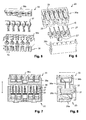
- FIG. 5 shows in an exploded view a contacting unit 33 in the form of a plug, with spring contacts 37 and a plug housing of a housing lower part 36a and a lid 36b.
- the spring contacts 37 are exemplified as spring-type terminals respectively spring terminals.
- an insulating contact protection 38 is arranged as part of the lower housing part 36a around each contact area of a spring contact 37.
- FIG. 6 shows in an exploded view a contacting unit 23 in the form of a socket, with contact lugs 27 for contacting the spring contacts 37 of a plug and a socket housing of a housing lower part 26a and a cover 26b.
- One of the contact lugs is formed as a ground contact 27 'and has a Connection element for screwing and contacting with a metal housing. Between the contact lugs 27 each partition walls 29 are arranged.
- the outer width d a of the contact protection 38 is about 3.5 millimeters and the inner width d i of the recess 28 is about 4.5 millimeters.
- the connector has dimensions of a few centimeters, for example, a width (in the direction along which the contacts are lined up) of two to five centimeters and a height (in the first direction) of one to three or four centimeters.
- FIGS. 7 to 8 show sections through the contacting units in the assembled state (corresponding to the mounted state of the lamp 1), with the elements already described.
- FIG. 7 is a relative displaceability between first contacting unit 23 and second contacting unit 33 in a first direction, in which the contacting units 23, 33 are pluggable, shown by a double arrow.
- This displaceability is, for example, two, three, five, ten millimeters or more, without the electrical contacts between the two contacting units 23, 33 being impaired.
- FIG. 8 is a relative displaceability between the first contacting unit 23 and the second contacting unit 33 in a second direction, perpendicular to the first direction, shown by a double arrow.
- This displacement is, for example, four, five, ten millimeters or more, without affecting the electrical contacts.
- the second direction runs parallel to the surface of the contact lugs 27.
- the displaceability in the first direction is two to three millimeters and in the second direction four to six millimeters.
Landscapes
- Engineering & Computer Science (AREA)
- General Engineering & Computer Science (AREA)
- Arrangement Of Elements, Cooling, Sealing, Or The Like Of Lighting Devices (AREA)
- Non-Portable Lighting Devices Or Systems Thereof (AREA)
- Fastening Of Light Sources Or Lamp Holders (AREA)
Applications Claiming Priority (1)
| Application Number | Priority Date | Filing Date | Title |
|---|---|---|---|
| CH5052012A CH706349A2 (de) | 2012-04-12 | 2012-04-12 | Leuchte und Steckverbindung. |
Publications (3)
| Publication Number | Publication Date |
|---|---|
| EP2650596A2 true EP2650596A2 (fr) | 2013-10-16 |
| EP2650596A3 EP2650596A3 (fr) | 2014-08-13 |
| EP2650596B1 EP2650596B1 (fr) | 2017-08-09 |
Family
ID=48446225
Family Applications (1)
| Application Number | Title | Priority Date | Filing Date |
|---|---|---|---|
| EP13405044.2A Not-in-force EP2650596B1 (fr) | 2012-04-12 | 2013-04-10 | Lampe et connecteur à fiche |
Country Status (4)
| Country | Link |
|---|---|
| EP (1) | EP2650596B1 (fr) |
| CH (1) | CH706349A2 (fr) |
| DK (1) | DK2650596T3 (fr) |
| NO (1) | NO2650596T3 (fr) |
Citations (1)
| Publication number | Priority date | Publication date | Assignee | Title |
|---|---|---|---|---|
| DE20114642U1 (de) | 2001-09-05 | 2002-03-14 | Kopp, Rupert, 72160 Horb | Leuchte für Leuchtstoffröhren mit getrenntem elektronischem Betriebsgerät |
Family Cites Families (6)
| Publication number | Priority date | Publication date | Assignee | Title |
|---|---|---|---|---|
| DE19746493C1 (de) * | 1997-10-22 | 1999-08-05 | Vossloh Schwabe Gmbh | Elektrisches Kupplungssystem |
| DE602005005392T2 (de) * | 2004-06-30 | 2009-04-23 | Tyco Electronics Nederland B.V. | Verbinder für elektronische Bauteile |
| US7448873B2 (en) * | 2007-01-08 | 2008-11-11 | Tyco Electronics Corporation | Connector assembly for end mounting panel members |
| DE102007030920B3 (de) * | 2007-07-03 | 2008-10-23 | Erni Electronics Gmbh | Steckverbinder |
| JP5171661B2 (ja) * | 2009-01-20 | 2013-03-27 | シャープ株式会社 | Led照明器具 |
| JP4719305B1 (ja) * | 2010-08-27 | 2011-07-06 | イリソ電子工業株式会社 | コネクタ |
-
2012
- 2012-04-12 CH CH5052012A patent/CH706349A2/de not_active Application Discontinuation
-
2013
- 2013-04-10 DK DK13405044.2T patent/DK2650596T3/da active
- 2013-04-10 EP EP13405044.2A patent/EP2650596B1/fr not_active Not-in-force
- 2013-04-10 NO NO13405044A patent/NO2650596T3/no unknown
Patent Citations (1)
| Publication number | Priority date | Publication date | Assignee | Title |
|---|---|---|---|---|
| DE20114642U1 (de) | 2001-09-05 | 2002-03-14 | Kopp, Rupert, 72160 Horb | Leuchte für Leuchtstoffröhren mit getrenntem elektronischem Betriebsgerät |
Also Published As
| Publication number | Publication date |
|---|---|
| DK2650596T3 (da) | 2017-11-20 |
| NO2650596T3 (fr) | 2018-01-06 |
| EP2650596A3 (fr) | 2014-08-13 |
| CH706349A2 (de) | 2013-10-15 |
| EP2650596B1 (fr) | 2017-08-09 |
Similar Documents
| Publication | Publication Date | Title |
|---|---|---|
| DE102008046983B4 (de) | Fahrzeuginnenraum-Beleuchtungslampeneinheit | |
| DE112014005994B4 (de) | Verbinder mit Bewegungsrichtungs-Wandlungsmechanismus | |
| DE102013226950A1 (de) | Profilleuchtensystem und Montageverfahren dafür | |
| DE102020132994A1 (de) | Elektrische Steckvorrichtung mit einem durch ein Gegengehäuse lösbaren Arretiermechanismus für ein Lagesicherungselement | |
| DE102017110385A1 (de) | Verbinderdose mit werkzeugloser Stifteinsatzdemontage | |
| DE102014116490A1 (de) | Anschlussvorrichtung für Mehrleiterkabel | |
| DE2055546A1 (de) | Elektrische Verbinderanordnung | |
| DE102007005737A1 (de) | Kopfstützensystem für einen Fahrzeugsitz | |
| EP4026204A1 (fr) | Dispositif de raccordement pour pilote de source lumineuse | |
| EP3015359B1 (fr) | Dispositif de fixation et mise en contact électrique d'un carénage d'un aéronef sur une structure porteuse | |
| EP2650596B1 (fr) | Lampe et connecteur à fiche | |
| DE202018106703U1 (de) | Wand- oder Deckenleuchte | |
| DE102006013144A1 (de) | Lichtbandleuchte | |
| EP2920852B1 (fr) | Insert de prise | |
| DE102004018381B4 (de) | Deckenleuchte | |
| EP3568885B1 (fr) | Dispositif de connexion électrique pour l'alimentation électrique de wagons accouplés d'un véhicule ferroviaire | |
| EP1372365B1 (fr) | Borne à connexion | |
| DE102024100353B4 (de) | Leuchte mit verriegelbarem Befestigungsabgriff und Verfahren zur Montage einer Leuchte | |
| DE102018131996B4 (de) | Leuchte und zu deren Realisierung vorgesehenes System und Verfahren | |
| DE102018132142A1 (de) | Steckverbinderanordnung zur Kontaktierung in mehreren Raumrichtungen | |
| EP3931924B1 (fr) | Assemblage avec une armoire électrique et au moins une barre multiprise | |
| EP3534473B1 (fr) | Appareil d'installation électronique de la technique des systèmes de bâtiments | |
| EP3577725A1 (fr) | Connecteur enfichable équipé d'un pont de connexion de conducteurs de protection | |
| DE102017102241B4 (de) | Steckdosenerweiterung | |
| DE102013104957B4 (de) | Steckverbindungsvorrichtung, Steckverbindung und konfektioniertes Kabel |
Legal Events
| Date | Code | Title | Description |
|---|---|---|---|
| PUAI | Public reference made under article 153(3) epc to a published international application that has entered the european phase |
Free format text: ORIGINAL CODE: 0009012 |
|
| AK | Designated contracting states |
Kind code of ref document: A2 Designated state(s): AL AT BE BG CH CY CZ DE DK EE ES FI FR GB GR HR HU IE IS IT LI LT LU LV MC MK MT NL NO PL PT RO RS SE SI SK SM TR |
|
| AX | Request for extension of the european patent |
Extension state: BA ME |
|
| PUAL | Search report despatched |
Free format text: ORIGINAL CODE: 0009013 |
|
| AK | Designated contracting states |
Kind code of ref document: A3 Designated state(s): AL AT BE BG CH CY CZ DE DK EE ES FI FR GB GR HR HU IE IS IT LI LT LU LV MC MK MT NL NO PL PT RO RS SE SI SK SM TR |
|
| AX | Request for extension of the european patent |
Extension state: BA ME |
|
| RIC1 | Information provided on ipc code assigned before grant |
Ipc: H01R 13/631 20060101ALN20140704BHEP Ipc: F21V 23/06 20060101ALI20140704BHEP Ipc: F21S 8/00 20060101AFI20140704BHEP |
|
| RBV | Designated contracting states (corrected) |
Designated state(s): AL AT BE BG CH CY CZ DE DK EE ES FI FR GB GR HR HU IE IS IT LI LT LU LV MC MK MT NL NO PL PT RO RS SE SI SK SM TR |
|
| 17P | Request for examination filed |
Effective date: 20150128 |
|
| 17Q | First examination report despatched |
Effective date: 20151019 |
|
| RIC1 | Information provided on ipc code assigned before grant |
Ipc: F21V 23/06 20060101ALI20160719BHEP Ipc: F21S 8/00 20060101AFI20160719BHEP Ipc: H01R 13/631 20060101ALN20160719BHEP |
|
| STAA | Information on the status of an ep patent application or granted ep patent |
Free format text: STATUS: EXAMINATION IS IN PROGRESS |
|
| GRAP | Despatch of communication of intention to grant a patent |
Free format text: ORIGINAL CODE: EPIDOSNIGR1 |
|
| STAA | Information on the status of an ep patent application or granted ep patent |
Free format text: STATUS: GRANT OF PATENT IS INTENDED |
|
| RIC1 | Information provided on ipc code assigned before grant |
Ipc: F21V 23/06 20060101ALI20170127BHEP Ipc: H01R 13/631 20060101ALN20170127BHEP Ipc: F21S 8/00 20060101AFI20170127BHEP |
|
| INTG | Intention to grant announced |
Effective date: 20170302 |
|
| GRAS | Grant fee paid |
Free format text: ORIGINAL CODE: EPIDOSNIGR3 |
|
| GRAA | (expected) grant |
Free format text: ORIGINAL CODE: 0009210 |
|
| STAA | Information on the status of an ep patent application or granted ep patent |
Free format text: STATUS: THE PATENT HAS BEEN GRANTED |
|
| AK | Designated contracting states |
Kind code of ref document: B1 Designated state(s): AL AT BE BG CH CY CZ DE DK EE ES FI FR GB GR HR HU IE IS IT LI LT LU LV MC MK MT NL NO PL PT RO RS SE SI SK SM TR |
|
| REG | Reference to a national code |
Ref country code: GB Ref legal event code: FG4D Free format text: NOT ENGLISH |
|
| REG | Reference to a national code |
Ref country code: CH Ref legal event code: EP Ref country code: AT Ref legal event code: REF Ref document number: 917251 Country of ref document: AT Kind code of ref document: T Effective date: 20170815 |
|
| REG | Reference to a national code |
Ref country code: IE Ref legal event code: FG4D Free format text: LANGUAGE OF EP DOCUMENT: GERMAN |
|
| REG | Reference to a national code |
Ref country code: DE Ref legal event code: R096 Ref document number: 502013007999 Country of ref document: DE |
|
| REG | Reference to a national code |
Ref country code: CH Ref legal event code: NV Representative=s name: FREI PATENTANWALTSBUERO AG, CH |
|
| REG | Reference to a national code |
Ref country code: DK Ref legal event code: T3 Effective date: 20171114 |
|
| REG | Reference to a national code |
Ref country code: SE Ref legal event code: TRGR |
|
| REG | Reference to a national code |
Ref country code: NL Ref legal event code: MP Effective date: 20170809 |
|
| REG | Reference to a national code |
Ref country code: LT Ref legal event code: MG4D |
|
| REG | Reference to a national code |
Ref country code: NO Ref legal event code: T2 Effective date: 20170809 |
|
| PG25 | Lapsed in a contracting state [announced via postgrant information from national office to epo] |
Ref country code: HR Free format text: LAPSE BECAUSE OF FAILURE TO SUBMIT A TRANSLATION OF THE DESCRIPTION OR TO PAY THE FEE WITHIN THE PRESCRIBED TIME-LIMIT Effective date: 20170809 Ref country code: LT Free format text: LAPSE BECAUSE OF FAILURE TO SUBMIT A TRANSLATION OF THE DESCRIPTION OR TO PAY THE FEE WITHIN THE PRESCRIBED TIME-LIMIT Effective date: 20170809 Ref country code: FI Free format text: LAPSE BECAUSE OF FAILURE TO SUBMIT A TRANSLATION OF THE DESCRIPTION OR TO PAY THE FEE WITHIN THE PRESCRIBED TIME-LIMIT Effective date: 20170809 Ref country code: NL Free format text: LAPSE BECAUSE OF FAILURE TO SUBMIT A TRANSLATION OF THE DESCRIPTION OR TO PAY THE FEE WITHIN THE PRESCRIBED TIME-LIMIT Effective date: 20170809 |
|
| PG25 | Lapsed in a contracting state [announced via postgrant information from national office to epo] |
Ref country code: ES Free format text: LAPSE BECAUSE OF FAILURE TO SUBMIT A TRANSLATION OF THE DESCRIPTION OR TO PAY THE FEE WITHIN THE PRESCRIBED TIME-LIMIT Effective date: 20170809 Ref country code: IS Free format text: LAPSE BECAUSE OF FAILURE TO SUBMIT A TRANSLATION OF THE DESCRIPTION OR TO PAY THE FEE WITHIN THE PRESCRIBED TIME-LIMIT Effective date: 20171209 Ref country code: GR Free format text: LAPSE BECAUSE OF FAILURE TO SUBMIT A TRANSLATION OF THE DESCRIPTION OR TO PAY THE FEE WITHIN THE PRESCRIBED TIME-LIMIT Effective date: 20171110 Ref country code: LV Free format text: LAPSE BECAUSE OF FAILURE TO SUBMIT A TRANSLATION OF THE DESCRIPTION OR TO PAY THE FEE WITHIN THE PRESCRIBED TIME-LIMIT Effective date: 20170809 Ref country code: BG Free format text: LAPSE BECAUSE OF FAILURE TO SUBMIT A TRANSLATION OF THE DESCRIPTION OR TO PAY THE FEE WITHIN THE PRESCRIBED TIME-LIMIT Effective date: 20171109 Ref country code: RS Free format text: LAPSE BECAUSE OF FAILURE TO SUBMIT A TRANSLATION OF THE DESCRIPTION OR TO PAY THE FEE WITHIN THE PRESCRIBED TIME-LIMIT Effective date: 20170809 Ref country code: PL Free format text: LAPSE BECAUSE OF FAILURE TO SUBMIT A TRANSLATION OF THE DESCRIPTION OR TO PAY THE FEE WITHIN THE PRESCRIBED TIME-LIMIT Effective date: 20170809 |
|
| REG | Reference to a national code |
Ref country code: FR Ref legal event code: PLFP Year of fee payment: 6 |
|
| PG25 | Lapsed in a contracting state [announced via postgrant information from national office to epo] |
Ref country code: RO Free format text: LAPSE BECAUSE OF FAILURE TO SUBMIT A TRANSLATION OF THE DESCRIPTION OR TO PAY THE FEE WITHIN THE PRESCRIBED TIME-LIMIT Effective date: 20170809 Ref country code: CZ Free format text: LAPSE BECAUSE OF FAILURE TO SUBMIT A TRANSLATION OF THE DESCRIPTION OR TO PAY THE FEE WITHIN THE PRESCRIBED TIME-LIMIT Effective date: 20170809 |
|
| REG | Reference to a national code |
Ref country code: DE Ref legal event code: R097 Ref document number: 502013007999 Country of ref document: DE |
|
| PG25 | Lapsed in a contracting state [announced via postgrant information from national office to epo] |
Ref country code: SK Free format text: LAPSE BECAUSE OF FAILURE TO SUBMIT A TRANSLATION OF THE DESCRIPTION OR TO PAY THE FEE WITHIN THE PRESCRIBED TIME-LIMIT Effective date: 20170809 Ref country code: IT Free format text: LAPSE BECAUSE OF FAILURE TO SUBMIT A TRANSLATION OF THE DESCRIPTION OR TO PAY THE FEE WITHIN THE PRESCRIBED TIME-LIMIT Effective date: 20170809 Ref country code: EE Free format text: LAPSE BECAUSE OF FAILURE TO SUBMIT A TRANSLATION OF THE DESCRIPTION OR TO PAY THE FEE WITHIN THE PRESCRIBED TIME-LIMIT Effective date: 20170809 Ref country code: SM Free format text: LAPSE BECAUSE OF FAILURE TO SUBMIT A TRANSLATION OF THE DESCRIPTION OR TO PAY THE FEE WITHIN THE PRESCRIBED TIME-LIMIT Effective date: 20170809 |
|
| PLBE | No opposition filed within time limit |
Free format text: ORIGINAL CODE: 0009261 |
|
| STAA | Information on the status of an ep patent application or granted ep patent |
Free format text: STATUS: NO OPPOSITION FILED WITHIN TIME LIMIT |
|
| 26N | No opposition filed |
Effective date: 20180511 |
|
| PG25 | Lapsed in a contracting state [announced via postgrant information from national office to epo] |
Ref country code: SI Free format text: LAPSE BECAUSE OF FAILURE TO SUBMIT A TRANSLATION OF THE DESCRIPTION OR TO PAY THE FEE WITHIN THE PRESCRIBED TIME-LIMIT Effective date: 20170809 |
|
| PG25 | Lapsed in a contracting state [announced via postgrant information from national office to epo] |
Ref country code: MT Free format text: LAPSE BECAUSE OF FAILURE TO SUBMIT A TRANSLATION OF THE DESCRIPTION OR TO PAY THE FEE WITHIN THE PRESCRIBED TIME-LIMIT Effective date: 20170809 |
|
| REG | Reference to a national code |
Ref country code: CH Ref legal event code: PCAR Free format text: NEW ADDRESS: POSTFACH, 8032 ZUERICH (CH) |
|
| PG25 | Lapsed in a contracting state [announced via postgrant information from national office to epo] |
Ref country code: MC Free format text: LAPSE BECAUSE OF FAILURE TO SUBMIT A TRANSLATION OF THE DESCRIPTION OR TO PAY THE FEE WITHIN THE PRESCRIBED TIME-LIMIT Effective date: 20170809 |
|
| REG | Reference to a national code |
Ref country code: IE Ref legal event code: MM4A |
|
| PG25 | Lapsed in a contracting state [announced via postgrant information from national office to epo] |
Ref country code: LU Free format text: LAPSE BECAUSE OF NON-PAYMENT OF DUE FEES Effective date: 20180410 |
|
| PG25 | Lapsed in a contracting state [announced via postgrant information from national office to epo] |
Ref country code: IE Free format text: LAPSE BECAUSE OF NON-PAYMENT OF DUE FEES Effective date: 20180410 |
|
| PG25 | Lapsed in a contracting state [announced via postgrant information from national office to epo] |
Ref country code: TR Free format text: LAPSE BECAUSE OF FAILURE TO SUBMIT A TRANSLATION OF THE DESCRIPTION OR TO PAY THE FEE WITHIN THE PRESCRIBED TIME-LIMIT Effective date: 20170809 |
|
| PG25 | Lapsed in a contracting state [announced via postgrant information from national office to epo] |
Ref country code: PT Free format text: LAPSE BECAUSE OF FAILURE TO SUBMIT A TRANSLATION OF THE DESCRIPTION OR TO PAY THE FEE WITHIN THE PRESCRIBED TIME-LIMIT Effective date: 20170809 Ref country code: HU Free format text: LAPSE BECAUSE OF FAILURE TO SUBMIT A TRANSLATION OF THE DESCRIPTION OR TO PAY THE FEE WITHIN THE PRESCRIBED TIME-LIMIT; INVALID AB INITIO Effective date: 20130410 |
|
| PGFP | Annual fee paid to national office [announced via postgrant information from national office to epo] |
Ref country code: CH Payment date: 20200324 Year of fee payment: 8 |
|
| PG25 | Lapsed in a contracting state [announced via postgrant information from national office to epo] |
Ref country code: CY Free format text: LAPSE BECAUSE OF FAILURE TO SUBMIT A TRANSLATION OF THE DESCRIPTION OR TO PAY THE FEE WITHIN THE PRESCRIBED TIME-LIMIT Effective date: 20170809 Ref country code: MK Free format text: LAPSE BECAUSE OF NON-PAYMENT OF DUE FEES Effective date: 20170809 |
|
| PG25 | Lapsed in a contracting state [announced via postgrant information from national office to epo] |
Ref country code: AL Free format text: LAPSE BECAUSE OF FAILURE TO SUBMIT A TRANSLATION OF THE DESCRIPTION OR TO PAY THE FEE WITHIN THE PRESCRIBED TIME-LIMIT Effective date: 20170809 |
|
| PGFP | Annual fee paid to national office [announced via postgrant information from national office to epo] |
Ref country code: FR Payment date: 20200420 Year of fee payment: 8 Ref country code: DK Payment date: 20200422 Year of fee payment: 8 Ref country code: NO Payment date: 20200422 Year of fee payment: 8 Ref country code: DE Payment date: 20200420 Year of fee payment: 8 |
|
| PGFP | Annual fee paid to national office [announced via postgrant information from national office to epo] |
Ref country code: SE Payment date: 20200427 Year of fee payment: 8 Ref country code: GB Payment date: 20200427 Year of fee payment: 8 Ref country code: BE Payment date: 20200427 Year of fee payment: 8 |
|
| PGFP | Annual fee paid to national office [announced via postgrant information from national office to epo] |
Ref country code: AT Payment date: 20200421 Year of fee payment: 8 |
|
| REG | Reference to a national code |
Ref country code: DE Ref legal event code: R119 Ref document number: 502013007999 Country of ref document: DE |
|
| REG | Reference to a national code |
Ref country code: DK Ref legal event code: EBP Effective date: 20210430 |
|
| REG | Reference to a national code |
Ref country code: NO Ref legal event code: MMEP |
|
| REG | Reference to a national code |
Ref country code: SE Ref legal event code: EUG |
|
| REG | Reference to a national code |
Ref country code: AT Ref legal event code: MM01 Ref document number: 917251 Country of ref document: AT Kind code of ref document: T Effective date: 20210410 |
|
| GBPC | Gb: european patent ceased through non-payment of renewal fee |
Effective date: 20210410 |
|
| REG | Reference to a national code |
Ref country code: BE Ref legal event code: MM Effective date: 20210430 |
|
| PG25 | Lapsed in a contracting state [announced via postgrant information from national office to epo] |
Ref country code: NO Free format text: LAPSE BECAUSE OF NON-PAYMENT OF DUE FEES Effective date: 20210430 Ref country code: AT Free format text: LAPSE BECAUSE OF NON-PAYMENT OF DUE FEES Effective date: 20210410 Ref country code: CH Free format text: LAPSE BECAUSE OF NON-PAYMENT OF DUE FEES Effective date: 20210430 Ref country code: LI Free format text: LAPSE BECAUSE OF NON-PAYMENT OF DUE FEES Effective date: 20210430 Ref country code: DE Free format text: LAPSE BECAUSE OF NON-PAYMENT OF DUE FEES Effective date: 20211103 Ref country code: SE Free format text: LAPSE BECAUSE OF NON-PAYMENT OF DUE FEES Effective date: 20210411 Ref country code: GB Free format text: LAPSE BECAUSE OF NON-PAYMENT OF DUE FEES Effective date: 20210410 Ref country code: FR Free format text: LAPSE BECAUSE OF NON-PAYMENT OF DUE FEES Effective date: 20210430 |
|
| PG25 | Lapsed in a contracting state [announced via postgrant information from national office to epo] |
Ref country code: DK Free format text: LAPSE BECAUSE OF NON-PAYMENT OF DUE FEES Effective date: 20210430 |
|
| PG25 | Lapsed in a contracting state [announced via postgrant information from national office to epo] |
Ref country code: BE Free format text: LAPSE BECAUSE OF NON-PAYMENT OF DUE FEES Effective date: 20210430 |