EP2651046A2 - Verfahren und Systeme zur Überprüfung der Konsistenz und Erkennung von Anomalien in automatischen Identifikationssystemsignaldaten - Google Patents
Verfahren und Systeme zur Überprüfung der Konsistenz und Erkennung von Anomalien in automatischen Identifikationssystemsignaldaten Download PDFInfo
- Publication number
- EP2651046A2 EP2651046A2 EP12189310.1A EP12189310A EP2651046A2 EP 2651046 A2 EP2651046 A2 EP 2651046A2 EP 12189310 A EP12189310 A EP 12189310A EP 2651046 A2 EP2651046 A2 EP 2651046A2
- Authority
- EP
- European Patent Office
- Prior art keywords
- message
- ais
- transmitter
- signals
- characteristic
- Prior art date
- Legal status (The legal status is an assumption and is not a legal conclusion. Google has not performed a legal analysis and makes no representation as to the accuracy of the status listed.)
- Granted
Links
Images




Classifications
-
- H—ELECTRICITY
- H04—ELECTRIC COMMUNICATION TECHNIQUE
- H04B—TRANSMISSION
- H04B7/00—Radio transmission systems, i.e. using radiation field
- H04B7/14—Relay systems
- H04B7/15—Active relay systems
- H04B7/185—Space-based or airborne stations; Stations for satellite systems
- H04B7/1851—Systems using a satellite or space-based relay
- H04B7/18513—Transmission in a satellite or space-based system
-
- G—PHYSICS
- G06—COMPUTING OR CALCULATING; COUNTING
- G06F—ELECTRIC DIGITAL DATA PROCESSING
- G06F11/00—Error detection; Error correction; Monitoring
- G06F11/07—Responding to the occurrence of a fault, e.g. fault tolerance
- G06F11/0703—Error or fault processing not based on redundancy, i.e. by taking additional measures to deal with the error or fault not making use of redundancy in operation, in hardware, or in data representation
- G06F11/0751—Error or fault detection not based on redundancy
Definitions
- Embodiments described herein relate to systems and methods for processing Automatic Identification System signals. More particularly, embodiments described herein relate to systems and methods for detecting anomalous Automatic Identification System (AIS) messages.
- AIS Automatic Identification System
- the Automatic Identification System is a maritime communications system designed for short-range (typically 20-30 nautical miles) ship-to-ship and ship-to-shore communications.
- the AIS system uses narrowband (i.e. 25 kHz Bandwidth) Very High Frequency (VHF) channels centered at 161.975 MHz and 162.025 MHz, with a possible additional channel at 157.375 MHz, and a communication method called Self-Organizing Time Division Multiple Access (SOTDMA).
- VHF Very High Frequency
- SOTDMA Self-Organizing Time Division Multiple Access
- the AIS system is specified in ITU document ITU-R M.1371-2, "Technical characteristics for a universal shipborne automatic identification system using time division multiple access in the VHF maritime mobile band", ITU 1998-2006, the entire contents of which is hereby incorporated by reference.
- the AIS system supports a number of different types of signal.
- the principal AIS signal sent by a ship is a position report that provides information pertaining to the ship's identification, location, course, speed, and other details.
- the AIS also includes the use of a receiver, enabling a ship to receive AIS signals emitted by ships around it.
- Each minute, each VHF channel is divided into 2,250 time slots, each of which can accommodate one 26.67 ms AIS transmission (i.e. AIS signal).
- the time slots are accurately synchronized to Coordinated Universal Time (UTC) typically using Global Positioning System (GPS), and each AIS unit reserves time slots for future AIS transmissions from the ship.
- Other AIS units within range can therefore maintain a map of reserved slots and avoid transmitting during these intervals. This self-organizing feature avoids signal collisions over the short ranges involved in surface transmissions.
- AIS AIS is now mandatory on all ships over 300 tons engaged on international voyages, and it is also being extended to other vessels. It was originally conceived as an aid to navigation and safety, and also has potential security applications for monitoring maritime traffic.
- a method for detecting anomalous Automatic Identification System (AIS) message signals in a plurality of AIS message signals received by at least one satellite in space comprising: identifying a plurality of message characteristics associated with the plurality of AIS message signals; computing one or more group characterization criteria for the plurality of AIS message signals based on the plurality of message characteristics; and computing a computed message characteristic for a selected message signal based on the one or more group characterization criteria; detecting whether an actual message characteristic associated with the selected message signal conforms to the computed message characteristic within a predetermined tolerance.
- AIS Automatic Identification System
- the method may further comprise: identifying a plurality of AIS message signals from a selected AIS transmitter in the plurality of AIS message signals; determining at least one transmitter characteristic based on the plurality of AIS message signals from the selected AIS transmitter; and using this transmitter characteristic to refine the estimates of other message characteristics associated with that particular transmitter.
- an apparatus for detecting anomalous Automatic Identification System (AIS) message signals in a plurality of AIS message signals received by at least one satellite in space comprising: a memory, the memory storing the plurality of AIS message signals; a processor, the processor configured to: identify a plurality of message characteristics associated with the plurality of AIS message signals; compute one or more group characterization criteria for the plurality of AIS message signals based on the plurality of message characteristics; and compute a computed message characteristic for a selected message signal based on the one or more group characterization criteria; detect whether an actual message characteristic associated with the selected message signal conforms to the computed message characteristic within a predetermined tolerance.
- AIS Automatic Identification System
- the processor may be further configured to: identify a plurality of AIS message signals from a selected AIS transmitter in the plurality of AIS message signals; determine at least one transmitter characteristic based on the plurality of AIS message signals from the selected AIS transmitter; and use this transmitter characteristic to refine the estimates of other message characteristics associated with that particular transmitter.
- the selected message signal is in the plurality of AIS message signals.
- the one or more group characterization criteria comprise a computational function. In some cases, computing the one or more group characterization criteria comprises fitting the computational function to the plurality of message characteristics.
- the computational function comprises a linear combination of spherical harmonics.
- the at least one transmitter characteristic comprises a transmitter timing offset and/or a frequency offset.
- the computed message characteristic comprises Doppler shift, propagation delay, and/or a position of the AIS transmitter.
- the computed message characteristic may also comprise at least one characteristic selecting from the group consisting of: amplitude of the message signal and polarization of the message signal.
- AIS signals are strong enough to be detected by a satellite. Satellites, and low earth orbiting (LEO) satellites in particular, may also provide coverage for areas that are out of range of coastal/ground stations.
- FOV field of view
- the large field of view (FOV) of a LEO satellite means that the LEO satellite may receive signals from large numbers of ships at once, particularly as the LEO satellite passes over high volume shipping areas, which typically results in a large number of AIS signals colliding or overlapping with one another.
- the large FOV of a LEO satellite means that ships in the FOV may be very far from each other and at great distances the SOTDMA communication method may not be effective at avoiding signal collisions. Propagation delays may also affect accurate time synchronization.
- LEO satellite based AIS detection one problem encountered in LEO satellite based AIS detection is that many of the AIS signals sent by ships will collide or overlap with one another. For example, it is estimated that there may be 2,000 ships in the FOV of a LEO satellite in high traffic areas. Each ship will typically send 10 AIS position reports per minute so for 2,000 ships a LEO satellite will receive 20,000 AIS signals per minute. This is a very large number compared to the number of available time slots (i.e. 4,500 across both VHF channels) and as a result many AIS signals will collide with one another.
- FIG. 1 shows a general diagram of an AIS processing system 10 including at least one LEO satellite 12 and a ground station 14 for receiving and decoding AIS signals.
- FIG. 1 illustrates numerous ships 16 that have an AIS transmitter device 18 for transmitting AIS signals that are received by the LEO satellite 12.
- an AIS transmitter device 18 for transmitting AIS signals that are received by the LEO satellite 12.
- only one satellite 12 is shown, but a plurality of satellites may be provided for receiving AIS signals.
- a given ship 16 will transmit AIS signals over two narrowband (i.e. 25 kHz) VHF channels.
- AIS VHF channels include AIS1 at 161.975 MHz, AIS2 at 162.025 MHz, and USAIS at 157.375 MHz.
- the transmitting unit of the AIS transmitter device 18 employs a 9.6 kbps Gaussian minimum shift keying (GMSK) modulation, which is commonly known to imply that the AIS signal will be contained within a 14 kHz bandwidth.
- GMSK Gaussian minimum shift keying
- the LEO satellite 12 is equipped with at least one VHF antenna (see Figures 2 and 3 ) and receives the AIS signal transmitted by the ship 16.
- the LEO satellite 12 travels at a high velocity, such as 7,500 m/s for example, and consequently the AIS signal received by the LEO satellite 12 undergoes a Doppler shift of up to +/- 3.5 kHz.
- the AIS signals received by the LEO satellite 12 will have a range of amplitudes, depending on the location of the ship 16 and its angular position as seen by the LEO satellite 12.
- the transmitting antenna used in the AIS transmitter device 18 of a given ship 16 does not radiate directly upwards, and this may create a reception hole directly underneath the LEO satellite 12.
- the radiation patterns of the transmitting antenna of the AIS transmitter device 18 tend to balance the reduced signal strength caused by increased range, and the range of received signal amplitudes is relatively modest, and is most likely less than 10 dB for most of the FOV of the LEO satellite 12.
- Received AIS signals may be pre-processed at the LEO satellite 12 to create digital input data, which is subsequently processed by a processing unit so that detected AIS signals can be decoded to extract the message segment contained therein.
- the digital input data is downlinked from the LEO satellite 12 to the ground station 14 where processing occurs to produce the extracted message segments, as will be explained with reference to FIG. 2 .
- LEO satellite 12 there may be more than one LEO satellite 12 that receives and pre-processes, as well as possibly detects and decodes, the AIS signals.
- one or more ground stations 14 may be used to decode the pre-processed AIS signals.
- the processing required for detection and decoding can be separated between the LEO satellite 12 and the ground station 14 in a variety of ways, with some or all of the processing being performed on the satellite, and the remainder of the processing being performed on the ground; this scheme can also be extended to the cases in which there is more than one LEO satellite 12 and one ground station 14, one LEO satellite 12 and more than one ground station 14, or more than one LEO satellite 12 and more than one ground station 14.
- data can be transmitted between the LEO satellite(s) and ground station(s) for processing in a variety of fashions.
- the embodiments described herein are with regards to a system with one LEO satellite 12 and one ground station 14, but the processing methodology can be extended to several LEO satellites and/or several ground stations. It is also conceivable that inter-satellite links (ISL) amongst a constellation of LEO satellites could be employed.
- ISL inter-satellite links
- the LEO satellite 12 comprises a receiver 20, a control unit 22, and a transmitter unit 26.
- the receiver 20 comprises a first receiver channel 28, and a second receiver channel 30.
- the first receiver channel 28 comprising a first receiver antenna 32, an RF front end 34, the latter comprising a front end filter and a low noise amplifier, a filter stage 36, an amplifier stage 38, a mixing stage 40, an ADC 42 and a filter bank 44.
- the second receiver channel 30 comprises similar components numbered 46 to 58. In some embodiments the second receiver channel 30 is not used, as will be described in more detail below. Also, in some embodiments, the mixing stages 40 and 54 are not used if the ADC 42 and 56 operates at a sufficiently adequate sampling rate.
- the transmitter 26 generally comprises a modulator 68, a transmitter unit 70 and a transmitter antenna 72.
- the receiver 20 may receive a plurality of AIS signals, pre-process the plurality of AIS signals to obtain digital input data.
- the digital input data can be provided to control unit 22.
- the digitized signal data can be modulated by the modulator 68 and transmitted via the transmitter antenna 72, as transmitted digitized signal data 74 to the ground station 14.
- the ground station 14 is equipped with a processing unit 24, control unit 76, a receiver 78 and a data store 80, such as a database stored on a suitable storage medium.
- the receiver 78 includes a receive antenna 82 and a de-modulator 84 to de-modulate the transmitted digitized signal data 74 that are received by the ground station 14.
- the control unit 76 controls the operation of the ground station 14, and can be used to retrieve the decoded message segments from the processor 24, store these decoded message segments on the data store 80, and later recall the stored decoded message segments.
- the ground station 14 can also include a transmitter (not shown) for sending the decoded message segments to interested parties. For example, various security and intelligence organizations may be interested in reviewing all validated decoded message segments, and as such it is necessary to store them in the data store 80 for later recall. For instance, the decoded messages can be distributed in encrypted form via the Internet.
- the processing unit 24 comprises a processing module 60, a refining module 62, a decoder 64 and a validation module 66.
- the refining module 62 is not used, as will be described in more detail below.
- the receiver 20 may comprise multiple antennas and multiple receiver channels; in FIG. 2 there are two receiver channels 28 and 30, one for each receiver antenna 32 and 46. However, in some embodiments only one receiver channel is used. Accordingly, for simplicity of explanation, the components of only one receiver path will be described.
- the receiver antenna 32 is a Very High Frequency (VHF) antenna that can be configured to receive AIS signals transmitted over the AIS1, AIS2 and USAIS channels.
- VHF Very High Frequency
- the receiver antennas 32 and 46 can be polarized in a different manner to provide an additional processing gain for detecting and decoding AIS signals.
- the receiver antenna 32 can have a right circular polarization
- the receiver antenna 46 can have a left circular polarization.
- the transmitter antenna used by the AIS transmitter device 18 of a given ship 16 transmits AIS signals with a vertical linear polarization, which generally implies that transmissions from particular locations have fairly well defined polarizations.
- this polarization may manifest itself as a phase shift between the AIS signals received by the two receiver antennas 32 and 46. That is, the AIS signal received by the receiver 46 may be a phase-shifted version of the corresponding AIS signal received by the receiver 32. This phase shift may provide a mechanism for distinguishing between overlapping AIS signals, or for detecting anomalous message signals.
- the AIS signals that are received by the circularly polarized receiver antennas 32 and 46 and correspond with one another generally have similar amplitudes.
- the receiver 20 is configured to receive an AIS signal in the Radio Frequency (RF) range and convert it to a baseband digital signal (i.e. digital input data).
- RF Radio Frequency
- This pre-processing and conversion performed by the receiver 20 may be achieved in numerous ways and incorporates standard operations in signal processing. For instance, according to the exemplary embodiment shown in FIG. 2 , considering receiver channel 28, an AIS signal is first received by the receiver antenna 32 and processed by the RF front end 34.
- the RF front end 34 comprises filtering and amplification components.
- the filtering components provide a first level of filtering to remove interfering signals, including intermodulation products caused by out of band carriers, as well as other noise.
- the filters may generally only have modest selectivity, but generally have very low loss since any loss at this stage comes directly off the overall system noise figure.
- the filtering components can include a VHF filter, which can be an LC type filter, and the amplification components may comprise a low noise amplifier following the first level of filtering to boost the signal to a reasonable level.
- the output of the RF front end 34 then can be processed by the filter stage 36 that provides another level of more selective filtering.
- the filter stage 36 includes a wide band channel filter with a passband for transmitting all three AIS channels (i.e. AIS1 at 161.975 MHz, AIS2 at 162.025 MHz, and USAIS at 157.375 MHz).
- AIS1 at 161.975 MHz
- AIS2 at 162.025 MHz
- USAIS at 157.375 MHz
- two combined filters may be used, one filter for the AIS1 and AIS2 channel and one filter for the USAIS channel, which may eliminate some interference between the two channels (i.e. AIS1/AIS2 and USAIS).
- the filter stage 36 generally employs a surface acoustic wave filter that can provide the sharp filtering that is needed.
- the received signals then can be processed by the amplifier stage 38 for adjustment of signal amplitude so that the full quantization range of the ADC 42 can be utilized during digitization.
- the amplification stage 38 comprises variable gain amplifiers and feedback can be provided from the mixing stage 40 so that an automatic gain control (AGC) block (not shown) in the amplifier stage 38 or the mixing stage 40 can adjust the amount of gain, or alternatively attenuation, that is provided by the amplifier stage 38.
- the control unit 22 can comprise an AGC component for controlling the amount of gain, or attenuation, provided by the amplifier stage 36.
- the receiver channel 28 employs distributed amplifying and filtering using several amplification and filtering components to reduce the performance burden on any one of the components and avoid any non-linearities that may otherwise be encountered.
- the way in which amplification is distributed throughout this RF processing chain is a matter that depends on detailed considerations of power consumption, noise figure, and intermodulation products.
- the output of the amplifier stage 38 is then processed by the mixing stage 40, and digitized by the ADC 42.
- the mixing stage 40 downconverts the VHF signals to an Intermediate Frequency (IF) band such as 25 MHz, which means that a lower sampling rate can be employed to reduce the requirements of the ADC 42.
- the ADC 42 samples the data. If a sufficiently fast ADC is available, with sampling rates greater than 400 MHz for example, then the conversion to an intermediate frequency can be omitted altogether and digitization can occur at this point. If an I and Q mixer were used, then the mixing stage 40 can provide output data at baseband.
- the mixing stage 40 also generally comprises filters and amplifiers to provide further filtering and amplification or buffering. For example, filtering is employed at the output of the mixing stage 40 to eliminate image bands and local oscillator leakage.
- the mixing stage 40 can comprise a post mixer IF filter which can be an LC type filter.
- the digitized data is then processed by the filter bank 44.
- the filter bank 44 comprises means for downconversion to baseband, and narrowband filters to remove all out of band signals. For instance, a 20 kHz bandwidth linear phase digital filter can be used for each AIS channel to account for the expected range in possible Doppler shifts. A component for performing decimation (not shown) can also be included at this point to reduce the output sampling rate.
- a Digital Signal Processor can be used to implement the filter bank 44. In this case, the DSP can downconvert the digitized data to baseband, perform narrowband filtering, and perform decimation to produce digital input data.
- the AD6620 digital receive signal processor is one example of a DSP that can be used to produce digital input data that includes I and Q baseband data for each of the AIS channels.
- Control unit 22 receives the digital input data from the receiver 20, and provides this data to the transmitter 26 which possibly encrypts, then modulates and transmits this data as transmitted digitized signal data 74 to the ground station 14.
- the modulator 68 may employ various digital modulation techniques such as a phase-shift keying (PSK) digital modulation scheme (i.e. modulates the phase of a signal). Examples include quadrature PSK or a higher-order PSK such as 8-PSK.
- the digitally modulated signal data may then be received by the transmitter unit 70 which includes circuitry for generating analog signals that correspond to the digital data, upconverts these analog signals to the frequency range required for transmission, and amplifies these signals so that they have the required signal strength that is needed for transmission to the ground station 14. These signals are then provided to the transmitter antenna 72 for transmission to the ground station 14.
- the transmitter antenna 72 at the LEO satellite 12 and the receiver antenna 78 at the ground station 14 can be configured for operation in, for example, the S band or the X band.
- the transmitter 26 may comprise an encryption module (not shown) for encrypting the digital signal data before the modulator 68 modulates these message segments.
- the ground station 14 includes a corresponding decryption module (not shown) to decrypt the received data, after demodulation, to recover the original digital signal data.
- the receiver 78 of the ground station 14 receives the transmitted digitized signal data 74, and pre-processes the received AIS signals to produce digital input data.
- receiver 78 may de-modulate the digitized signal data via de-modulator 84 to produce received digital input data that is provided to the processing unit 24 in order to detect and decode candidate AIS message signals.
- This pre-processing may comprise fairly standard signal processing operations that can be performed with standard commercial hardware.
- the organization of the hardware and the processing can be modified in various ways as is commonly known by those skilled in the art. Accordingly, the embodiments discussed herein are simply intended to provide exemplary illustrations for performing this pre-processing.
- the digital input data then can be provided to the processing unit 24 for detection and decoding of the AIS message segments.
- the processing unit 24 may provide the capability for parallel processing to potentially reduce computation time, as is commonly understood by those skilled in art.
- processing of the digital input data may be shared with, or offloaded to, another processing unit 24.
- the processing unit 24 can be provided to the processing module 60 for processing.
- the processing module 60 processes the digital input data to identify one or more candidate message signals and determine a corresponding Doppler offset estimate and time estimate for each candidate message signal.
- the processing module 60 generally processes the digital input data by employing correlation techniques. For example, the processing module 60 can process the digital input data with a plurality of predefined signals that correspond to Doppler offsets of a predetermined AIS code sequence (e.g. a training sequence and start flag as shown in FIG. 3 can be used) to compute a plurality of correlation signals.
- a predetermined AIS code sequence e.g. a training sequence and start flag as shown in FIG. 3 can be used
- the processing module 60 may scan the correlation signals for correlation peaks (i.e. amplitude peaks) that exceed other peaks by a predetermined amount in order to identify the one or more candidate message signals.
- the correlation peak should exceed the amplitude of any subsequent peaks that lie within one signal length (i.e. 26.67 ms) of the data segment that is being analyzed.
- the correlation peak associated with a candidate message signal may provide an estimate of its Doppler offset and timing.
- the processing module 60 may be implemented using a cluster of processing components, described in more detail below, to compute the correlation signals using the predefined signals that correspond to Doppler offsets of a predetermined AIS code sequence in parallel to reduce the processing time.
- the processing module 60 may provide this group of candidate message signals to the refining module 62.
- the refining module 62 refines the group of candidate message signals by sorting the candidate message signals in this group by their corresponding time estimate.
- the refining module 62 may then determine whether any of these candidate message signals is repeated at a different Doppler offset estimate; if so, the refining module 62 removes all repeated candidate message signals from the group.
- the refining module 62 may remove all candidate message signals that are overlapped on their high time side by a stronger candidate message signal. This operation ensures that time is not wasted trying to decode questionable signals.
- the remaining candidate message signals comprise a refined group of candidate message signals, which the refining module 62 forwards to the decoder 64.
- the refining module 62 will typically alleviate the computational time required to decode all candidate message signals that are identified by the processing module 60, since the refined group of candidate message signals is generally (much) smaller in size than the group of candidate message signals identified by the processing module 60.
- the decoder 64 decodes one or more candidate message signals to obtain (or extract) the AIS message segment contained therein. In some embodiments, the decoder 64 receives the one or more candidate message signals from the processing module 60. In other embodiments, the decoder 64 receives the one or more candidate message signals from the refining module 62. In both cases, there are no predetermined code sequences within the message segment, so correlation techniques may not be helpful to decode a candidate message signal. In some circumstances, the candidate message signals may contain specific identification numbers, such as a Maritime Mobile Service Identity, or specific locations. As such, in some cases, there may be some fixed known code sequences within the message segment, which can be used to employ correlation techniques.
- the decoder 64 may employ various decoding procedures to extract message segments from the one or more candidate message signals.
- the decoder 64 may perform Viterbi Decoding (or more generally dynamic programming), as is explained in further detail below.
- a more precise Doppler offset estimate and time estimate is obtained for the candidate message signals, as will be discussed below, regardless of whether the candidate message signals have been previously refined.
- the validation module 66 may initially validate the decoded message segments for proper AIS signal message formatting by checking each decoded message segment for valid bit stuffing and then removing all bit stuffing.
- the bit stuffing is specified by the AIS signal specification, where a 0 is inserted into the message segment after any sequence of five successive 1's in the message and frame check sequence portion of the message segment. This is done to avoid the occurrence of spurious start and stop flags.
- the validation module 66 may also verify a frame check sequence field of the decoded message segment. If a decoded message segment passes these checks, it may be temporarily stored in a list of decoded message segments that have been validated initially.
- validation module 66 may perform additional validation as described further herein.
- the processing unit 24 can be a computing cluster and may be implemented as a parallel processing system using standard components such as a server (local or remote), a plurality of processors, a non-transitory computer readable memory (both volatile and/or non-volatile) and a computer operating system. These components can be linked via local or wide area network. Although they are illustrated as being contained within a single ground station 14, various components may be geographically remote with respect to the ground station 14.
- the system 10 can be configured such that the downlink path accommodates a data transmission rate of around 3 Mbps.
- control units 22 and 76 and the processing unit 24 also can be implemented using a processor.
- the control unit 76 and the processing unit 24 can be implemented with the same processor.
- the transmitter 26 and the receiver 78 can also employ a processor.
- the various embodiments of the LEO 12 and the ground station 14 generally employ a combination of hardware and software.
- the components of the processing unit 24, the modulator 68 and the de-modulator 84 can be implemented using software executed by a processor.
- there can be embodiments in which these components are organized in a different fashion but perform the same functionality.
- FIG. 2 illustrates a particular system configuration
- the processing unit can be implemented at a LEO satellite, such as the processing module.
- the AIS message signal 120 includes a ramp-up field 122, a training sequence 124, a start flag field 126, and a message segment field 128 including a ship ID field 130, a longitude field 132, a latitude field 134 and several other fields 136.
- the AIS message signal 120 also includes a Frame Check Sequence (FCS) field 138, an end flag field 140 and a buffer field 142.
- FCS Frame Check Sequence
- the ramp-up field 122 usually coincides with the powering up of the AIS transmitter device 18 of a given ship 16.
- the training sequence field 124 is included to allow the receiver of a conventional AIS 18 to perform carrier recovery.
- the start flag field 126 is a predetermined AIS code sequence that indicates the start of the message field.
- the message segment field 128 contains information relating to the ship 16 from which the AIS signal was sent, such as the ship ID 130 and the longitude 132 and the latitude 134 of the ship location.
- the other fields 136 also include information related to the ship including the navigation status, rate of turn, true heading, etc. as well as other information such as a time stamp indicating when the information was obtained.
- the frame check sequence field 138 is used for error detection, and can be used to determine whether any AIS message signal data is altered during transmission.
- the end flag field 140 is another predetermined AIS code sequence that indicates the end of the message and frame check sequence fields.
- the buffer field 142 generally contains no information and is included to prevent the message overlapping into an adjacent time slot; the transmitter typically starts to power down once the stop flag is transmitted.
- AIS transmitter devices may exhibit some timing and frequency error, due to specific implementation and construction details. However, in general, most AIS transmitter devices can be assumed to be transmitting valid information. But there may be certain AIS transmitter devices that transmit intentionally incorrect data, for example to falsify position reports, spoof position reports of other ships, or simply due to malfunction.
- Conventional AIS detection systems may lack the ability to validate the accuracy of AIS position reports.
- they may offer limited ability to validate AIS message signals, they may rely on precise time and position references on board the satellite (e.g., satellite ephemeris and highly accurate synchronized time sources).
- precise time and position references on board the satellite e.g., satellite ephemeris and highly accurate synchronized time sources.
- one conventional system checks reported position by determining the propagation delay from the ship to the satellite and comparing this to a predicted delay based on the reported ship position as compared to the satellite position.
- This requires precise position references on board the satellite and a satellite timing clock that is accurately synchronized to that on the ship, and it can only be used to determine the range of the transmitter from the satellite.
- Inaccuracies in the on-board time source, or the lack of ephemeris for the specific satellite that received the AIS message signals in question may significantly degrade or disable the ability to perform such validation.
- the described methods and systems describe embodiments that enable the validation of AIS message signals, for example to detect ships that are attempting to falsify their position reports or to falsify their identities.
- the described methods and systems can perform validation without the need for satellite ephemeris or for synchronized clocks, and can generate a model of the satellite position from a set of AIS message signals received from a plurality of ship-based transmitters. This may be of particular interest for national and international security applications, and may be used in conjunction with other systems, such as space-based radar, or as part of a comprehensive shipping traffic monitoring system.
- AIS Automatic Identification System
- auxiliary parameters or message characteristics obtained during the AIS message decoding, can be used to validate the reported AIS transmitter positions and to characterize each AIS transmitter itself.
- the proposed method checks position using both timing and Doppler shift, and can obtain both range and directional information. No on-board references are required; the necessary calibration is derived from the data set itself. In addition, the method has provision for characterizing the timing and frequency errors of individual transmitters, and this can be used to enhance the accuracy of the position determinations.
- AIS was conceived as a means for improving short range ship to ship communications and enhancing maritime safety, it also has many other potential applications. Detection of AIS signals by LEO satellites is possible, and constellations of such satellites provide a means for global monitoring of shipping traffic, which is of considerable interest for national and international security.
- Satellite detection also enables a number of auxiliary parameters or message characteristics to be determined, some of which may be useful to characterize individual transmitters, and some of which may be useful to characterize the locations of those transmitters. This enables a number of consistency checks to be performed, and allows anomalous messages to be flagged.
- parameters and message characteristics that can be identified comprise:
- amplitude and phase shift parameters may be included to characterize all of the available signals.
- each satellite has at least two differently polarized antennas.
- the use of at least two antennas with different polarizations allows the polarization orientation of an incoming AIS signal to be determined, and allows increased discrimination between signals overlapping in time.
- VHF antennas that can be mounted on small LEO satellites have very little directivity, and give very little indication of the origins of an AIS signal. If additional spatially separated antennas are available then directivity can be further increased.
- the described methods and systems can also be used with a single antenna polarization, possibly with reduced accuracy and directivity.
- the first five of the above parameters generally provide information about the location of the AIS transmitter, while parameters such as the training sequence and modulation index generally provide information about the transmitter itself.
- each AIS message generally contains reported position (e.g., provided in values of latitude and longitude).
- the arrival time and the Doppler shift can be of particular importance for providing an independent determination of position.
- the propagation delay of an AIS signal from a ground based transmitter to a LEO satellite typically varies from between 2 to 10 ms, depending on whether the transmitter is directly below the satellite or is on the horizon. Transmitters are accurately synchronized to UTC, and if the satellite also has a synchronized clock, then the propagation delay of a message relative to the start of its transmission slot can be determined from the arrival time.
- timing jitter may be present in the transmitter (e.g., the AIS standard permits up to ⁇ 3 bits, which equates to ⁇ 312 ⁇ s, which can result in a position determination error of ⁇ 94 km).
- the propagation delay can be calculated, and this expected value compared to the directly measured value.
- the Doppler shift of an AIS message signal can also be used in a similar way to determine position. If the location, speed and direction of travel of the satellite are known, then the expected Doppler shift for a given transmitter location can be computed and compared to the Doppler shift measured at the satellite. However, this measurement is also subject to error, principally due to the frequency tolerance on the transmitter. In practice, frequency errors are generally indistinguishable from Doppler shift.
- the AIS standard permits an error of ⁇ 3 ppm ( ⁇ 480 Hz), which is approximately 14% of the maximum expected Doppler shift in satellite detection. Accordingly, frequency error may produce position estimation errors comparable to those associated with the propagation delay.
- the signal amplitude and polarization of AIS messages can also be used to provide positional information.
- the received signal amplitude is weakly dependent on the transmitter location, as the increased transmitter antenna gain at low elevations may balance out the effects of the greater distance to the satellite.
- the signal amplitude may be dependent on effects such as multi-path propagation and atmospheric attenuation.
- Transmitter antennas generally have a vertical polarization, and, in principle, two nearby ships should produce similarly polarized signals at the satellite. In practice, however, errors may arise due to the motion of the ships. Moreover, the signal polarization may experience a large Faraday rotation in the ionosphere (in some cases several full rotations). In simulations, this strong dependence on the propagation path limited the ability to estimate position based on polarization alone.
- the training sequence is part of a standard preamble in AIS signals that is used to synchronize AIS receivers. This generally provides no information about the transmitter location but can serve to characterize the transmitter itself.
- the AIS standard specifies that the training sequence should be a sequence of twenty-four (24) alternating 0's and 1's, and in practice this may be either "010101" or "101010", depending on the transmitter.
- the AIS standard specifies that non-return to zero inverted (NRZI) encoding of the data is to be used.
- NRZI non-return to zero inverted
- a signal transition occurs for a 0 in the input data stream, and no transition occurs for a 1 in the input data stream.
- the sense of the transitions at a given point in the training sequence may be -1 ⁇ 1 or 1 ⁇ -1, and both situations may arise in practice. These factors are generally fixed for a given transmitter. Therefore characterization of the training sequence, both in terms of bit selection and transition sense, can provide a useful characterization of the transmitter.
- the modulation index used by a transmitter should have a value of 0.5, meaning that each bit in the input sequence advances or retards the signal phase by ⁇ /2.
- transmitters generally fail to honor this requirement with any great accuracy. Accordingly, modulation index values in the range of 0.4 to 0.6 may be encountered. However, the modulation index generally remains remain relatively constant for a given transmitter, and therefore may provide another useful characterization.
- the above parameter set may comprise statistical error estimates for the accuracy of the message characteristics or parameters, which can provide a useful comparative guide.
- the mismatch is equal to 1 when the two functions are identical apart from a multiplicative constant.
- Mismatch values between the ideal waveform and the actual signals received by the two antennas can also be included in the parameter set. These can provide a useful figure of merit for assessing parameter reliability when strong interference is present.
- Position dependent parameters generally facilitate the detection of ships spoofing their positions.
- Transmitter dependent parameters can be used to detect ships trying to spoof their identities.
- propagation delay and Doppler shift are only weakly dependent on the properties of the transmission medium, a property that can make these parameters suitable for verifying transmitter position. Moreover, propagation delay and Doppler shift can provide independent position estimates that are in many ways complementary.
- the sensitivity of propagation delay to transmitter position is generally at a minimum when a ship is located directly under the receiving satellite.
- the variation of sensitivity with increasing distance is quite slow, particularly at long ranges.
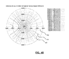
- FIG. 4A there is illustrated a plot of AIS transmitter distance from a satellite, as a function of angle for various propagation delays.
- the satellite is assumed to have an orbital radius of 7024 km. This orbital radius causes the minimum propagation delay (i.e., for a transmitter directly under the satellite) to be approximately 2.2 ms, while for a ship on the horizon the propagation delay is approximately 9.9 ms.
- the minimum propagation delay plot is shown as a point in the centre of the plot.
- the horizon propagation delay plot is shown as contour line 414. Additional contour lines 402 to 412 illustrate other propagation delays. It can be observed in FIG. 4A that the contour lines are closest together at long ranges, indicating that these are the regions of greatest sensitivity, where a shift in a ship's position produces the greatest change in propagation delay. Nevertheless, propagation delay generally provides fairly constant range sensitivity.
- Doppler shift can be another useful parameter for verification purposes.
- the Doppler shift can be approximately zero, but this is also the point where the rate of change of Doppler shift with respect to position is greatest.
- a change in Doppler shift of 10 -6 corresponds approximately to a 26 km change in the position of such a ship in the direction of the satellite's orbit.
- Doppler shift varies very slowly with position.
- contour line 452 corresponds to a Doppler shift of -2.25x10 -5 . From right to left, each successive contour line represents an increase in Doppler shift of 0.25x10 -5 .
- contour line 454 corresponds to a Doppler shift of -2.00x10 -5
- contour line 456 corresponds to a Doppler shift of -1.75x10 -5 and so on (except that there is no contour line for zero Doppler shift).
- FIG. 4B is an approximation, which takes into account Doppler effects due to the motion of the satellite, but not those due to the rotation of the earth.
- contour 452 for a Doppler shift of -2.25x10 -5
- contour 454 for a Doppler shift of -2.00x10 -5
- the corresponding change in range is approximately 400 km for a Doppler shift of 10 -6 . Accordingly, at longer ranges, measuring change in Doppler shift can be less accurate than the corresponding measurement based on propagation delay.
- both the expected propagation delay and the expected Doppler shift can be calculated for a given transmitter location.
- the Doppler shift can also be measured directly, as can the propagation delay, though f or Doppler shift the local time reference (e.g., clock) on the satellite does not need to be accurately synchronized to UTC. These measured values can then be compared to the expected values to determine the reliability of the reported position.
- the synchronized clock and accurate position and velocity information would normally rely on GPS, and the necessary information would need to be provided by the satellite when downlinking AIS data (e.g., embedded into the downlinked data).
- a synchronized time reference and accurate satellite position and velocity information e.g., ephemeris
- this GPS capability may not be present on the satellite, or may not be transmitted with downlinked AIS data.
- the arrival time and Doppler shift may still be used to check transmitter location. That is, a plurality of AIS message signals, forming a data set captured by one or more satellites, may be gathered. This plurality of AIS message signals can then be validated to identify selected message signals that are inconsistent with the characteristics of the larger plurality, as described further herein.
- FIG. 5 there is illustrated an exemplary process flow diagram of a method for detecting anomalous AIS message signals in a plurality of AIS message signals received by at least one satellite in space.
- Process flow 500 can begin at 505, by identifying a plurality of message characteristics associated with the plurality of AIS message signals.
- Message characteristics may comprise parameters associated with individual (e.g., selected) AIS message signals, such as propagation delay, Doppler shift, amplitude, polarization, etc.
- one or more group characterization criteria can be computed based on the set of message characteristics associated with the plurality of AIS message signals.
- the computation may comprise fitting a three variable function (e.g., where the variables comprise arrival time, and reported latitude and longitude) to selected message characteristics (e.g., propagation delay, Doppler shift, etc.), to provide a smoothed representation based on the average values for all of the ships in the field of view.
- a selected message may be identified for validation and, at 517, an actual message characteristic may be determined.
- the actual message characteristic may be a measured message characteristic (e.g., arrival time, Doppler shift) or a reported position contained within the message.
- message characteristics for the selected message can be computed based on the group characterization criteria, for comparison with actual (e.g., measured or reported) message characteristics at 525.
- the group characterization criterion is a smoothing function
- the computed message characteristics can be generated using the smoothing function.
- the estimated Doppler shift can be computed for a selected message based on the arrival time and the reported latitude and longitude of the transmitter contained within the selected message.
- an estimated transmitter position can be computed based on the measured message characteristics of selected messages. That is, the measured propagation delay and Doppler shift values for the selected message can be used, in conjunction with the group criteria, to estimate the latitude and longitude of the transmitter.
- the actual message characteristic of the selected message signal may be compared to the computed message characteristic, to determine if the characteristics conform within a predetermined tolerance.
- the predetermined tolerance may be a simple percentage value or a statistical measure such as standard deviation.
- the size of predetermined tolerance may also vary according to the value and type of the message characteristic being evaluated. For example, the predetermined tolerance may be larger when computations are based on Doppler shift and a large distance from the satellite is computed, since Doppler shift exhibits a relatively large range of possible values at longer distances.
- message characteristics may exhibit errors due to uncertainties originating from a variety of sources, including transmitter errors, variations in the transmission channel, receiver uncertainties, and data fitting errors.
- Table 1 illustrates estimated standard deviations associated with various types of uncertainties.
- Table 1 Error sources Parameter Transmitter Channel Receiver Data Fitting Propagation Delay (sec) 1.0x10 -4 Negligible 1.0x10 -6 3.0x10 -5 Doppler Shift (v/c) 1.0x10 -6 Negligible 1.0x10 -8 3.7x10 -8 Polarization (deg) 11.0 ⁇ 54.0 2.0 9.0
- the propagation delay is only marginally affected by variations in the propagation channel, and the estimated error in the receiver is very small, as is the residual error obtained when the smoothing function is fitted to the data.
- the AIS standard permits a maximum synchronization error for transmitters of ⁇ 3 bits.
- the standard deviation for the timing error can be estimated at 1.0x10 -4 s. This uncertainty dominates all of the others, and would limit the sensitivity of any position checking to approximately 30 km.
- the sensitivity of propagation delay to position is a minimum when a ship is located directly under the satellite, but the variation of sensitivity with distance is quite slow, particularly at long ranges.
- the standard deviation for spoofed or anomalous AIS messages typically exceeds 3-4 standard deviations from their expected values. Accordingly, the predetermined tolerance can be set to at least 3 standard deviations, or even 4 standard deviations for rigorous checking.
- the associated selected AIS message signal may be flagged as anomalous at 530. Otherwise, the AIS message signal may be flagged as valid.
- fitting functions that are linear combinations of a certain group of basis functions such as spherical harmonics may be used.
- the computation of the resulting spherical harmonic coefficients may lead to computing the solution of a set of linear equations.
- the accuracy of position estimates may be limited by the timing jitter and frequency tolerances of the individual AIS transmitters. Accordingly, in some cases, such estimates may lack a position resolution better than 50 km. However, in any given plurality of AIS message signals, there may be multiple message signals from an individual transmitter. Accordingly, estimation of the transmitter's systematic timing and frequency offsets can allow for the refinement of the group characterization criteria (e.g., smoothing function) and thereby improve the position estimation accuracy.
- the additional data from an individual transmitter can also be used to characterize the transmitter itself, which can be useful if one transmitter is attempting to spoof another.
- the timing delay of a message relative to the start of its transmission slot is a useful characteristic for the purposes of consistency checking and AIS message validation. In some cases, the delay may be as much as 10 ms.
- This timing delay can be determined from the arrival time of an AIS message signal if the satellite local time reference is synchronized to the same source as that of the AIS transmitter (e.g., GPS). However, even without such synchronization, the time delay can still be determined up to an arbitrary time offset. This arbitrary time offset is not necessary to perform message signal consistency checking or validation.
- T D t A - t S ⁇ t A / t S ⁇
- t A is the message arrival time referred to some arbitrary start time
- ⁇ x ⁇ is a floor function that gives the largest integer that is less than or equal to x .
- the T D values thus obtained naturally fall in a band approximately 8 ms wide, corresponding to the range of delays (2 to 10 ms) observed in practice, and within this band the T D values give the correct relative propagation delays of all the messages in the data set, though all are arbitrary up to some constant time offset.
- FIG. 6 illustrates the results of applying this transformation to a sample plurality of AIS message signals captured by a satellite over a ninety second interval.
- the arrival time of each AIS message signal is plotted against the value of T D .
- there are a few messages that lie outside the possible range of propagation delays e.g., 0-8 ms. This indicates the presence of some unsynchronized transmissions for which it may not be possible to check the propagation delays by any means.
- Equations (3) and (4) are shown represented in terms of polar angles ( ⁇ and ⁇ ) referred to some suitably chosen set of axes. This is purely for mathematical convenience, and the polar angles can be obtained directly from the reported latitude and longitude, or vice versa.
- This fitting procedure does not require precise information about the satellite position or velocity, and does not require a clock synchronized to UTC.
- the message data set can be used to provide calibration. Detection of anomalous AIS message signals can thereafter be performed by identifying messages with T D and D values that deviate from the fitting functions by more than a predetermined threshold.
- equations (5) and (6) a least squares fitting criterion is used. Other criteria can also be used, but least squares may be the easiest mathematically. Least squares fitting may also be desirable when errors are normally distributed, as the normal or Gaussian distributions may be reasonable representations of the errors encountered in practice.
- a suitable functional form can be selected for the functions f and g .
- a form may be chosen that uses a linear combination of fixed basis functions; the function coefficients can then be determined by solving a system of linear equations in the usual fashion.
- At least one form that can be suitable for the applications described herein is described by F.W.J. Olver, D.W. Lozier, R.F. Boisvert and C.W. Clark, eds., "NIST Handbook of Mathematical Functions", New York: Cambridge University Press, 2010, the entire contents of which are hereby incorporated by reference.
- Equations (7) and (9) are general, and in general any function f ( ⁇ , ⁇ , t ) can be represented in this way.
- the maximum order of the spherical harmonics can be limited, and the time dependent coefficients can be represented in terms of discrete parameters.
- spherical harmonic order need not be greater than 10.
- the associated Legendre functions may have many representations, but for practical computation they can generally be determined by recurrence relationships.
- the recurrence relationship: n - m ⁇ P n m x 2 ⁇ n - 1 ⁇ x ⁇ P n - 1 m x - n + m - 1 ⁇ P n - 2 m x which is stable in upward recurrence in n for any value of x , may be a suitable choice.
- the polar angles ⁇ and ⁇ can be referred to any chosen set of axes.
- a set of axes that rotates at least approximately with the satellite may be convenient to use in practice, as this can minimize the time dependence of the a mn (t) coefficients.
- This choice of axes also eliminates the need to know the position of the satellite in its orbit (e.g., Equation (7)) as, for a circular orbit, one arc of the orbit may be transformed to any other by a constant rotation with respect to the new axes, and, with suitably chosen combinations of spherical harmonics, Equation (7) is invariant under such transformations.
- Comparisons between parameters or message characteristics for selected AIS messages, and values obtained from the fitting functions f and g may be subject to a variety of errors, including transmitter errors, variations in the transmission channel, receiver uncertainties and data fitting errors.
- transmitter timing jitter and frequency error are generally the most significant factors.
- Properties of the transmission channel may significantly affect the polarization shift, due to Faraday rotation in the ionosphere. To a lesser extent, the transmission channel may also affect signal amplitude, although the propagation delay and the Doppler shift are generally not affected significantly.
- Determination and detection of AIS message signal characteristics or parameters at the receiver may need to be performed in the presence of noise and interference, and thus may be subject to some errors. However, in general, such errors can be estimated statistically, and generally have a significantly lesser effect than transmitter errors.
- the described group characterization and data fitting procedure is an averaging process, and the presence of some residual errors can be tolerated with little negative effect.
- position determination can generally be performed primarily based on the propagation delay and Doppler shift.
- the accuracy achievable with these parameters may be strongly dependent on the ship's location relative to the satellite.
- accuracy can be improved by accounting for, or removing, some of the systematic errors associated with transmitters.
- frequency error for a selected transmitter is likely to remain constant during a data capture interval (e.g., a ship may remain in view of the satellite for up to ten minutes).
- the timing jitter in a particular transmitter may also have a significant systematic component over short intervals.
- MMSI Maritime Mobile Service Identity
- transmitter characteristics such as offsets for the systematic timing and frequency errors of a particular transmitter, may be estimated and used to refine the group characterization criteria.
- Transmitter characteristics may be a specific class of message characteristic, which describe a characteristic of the transmitter itself, rather than the location of the transmitter.
- T i o and D i o are the unknown timing and Doppler offsets for a ship generating the i 'th message.
- the quantities T i o and D i o can be additional adjustable parameters in the least squares fit.
- at least two messages (and preferably ten or more) are used for each of the ships that are assigned offset parameters to facilitate the fitting process. When multiple messages from a particular ship are present, use of this approach can greatly reduce the position uncertainty, and can also provide some characterization of the transmitters themselves through the characteristic offset parameters T i o and D i o .
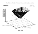
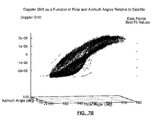
- FIGS. 7A and 7B there are illustrated plots of propagation delay and the Doppler shift, respectively, when applied to a set of simulated AIS data.
- the polar and azimuth angles ( ⁇ and ⁇ ) are referenced to a set of axes rotating approximately with the satellite; the origin of the axes is at the centre of the earth, and the z axis and x axes lie in the orbital plane of the satellite.
- the 'x' markers show the propagation delay and Doppler shift, respectively, as determined from the fitting functions for the reported latitude and longitude.
- the circled dot markers show the time delays and Doppler shift, respectively, determined directly from the individual AIS messages. It can be seen that the markers produce clearly defined surfaces, and that the 'x' and circled dot markers are generally in close agreement. However, some lines of 'x' markers can be seen that lie well outside these surfaces. These lines, which deviate beyond a predetermined threshold, represent transmitters that are reporting false positions or "spoofing".
- equations (22) and (23) are non-linear in ⁇ and ⁇ , but they can nonetheless be solved using iterative methods, such as the Newton-Raphson method, for example using the reported values, ⁇ i , and ⁇ i , as a starting point.
- a transmitter providing anomalous position data can then be flagged if the values of ⁇ and ⁇ deduced from the propagation delay and Doppler shift differed significantly from the reported values, ⁇ i and ⁇ i .
- the introduction of additional parameters to characterize systematic timing and frequency offsets associated with particular transmitters enables these parameters to be estimated as part of the general fitting procedure. This can reduce the uncertainties associated with particular transmitters, and significantly increase the accuracy of the associated position estimates.
- the estimated offsets provide some characterization of the individual transmitters, which may be used in conjunction with other parameters such as modulation index and training sequence polarity to test for transmitters trying to spoof their identities.
- three parameters could be used to determine satellite location and a further three parameters could be used to determine the velocity, where all of the parameters are functions of time.
- the time dependences could be parameterized by spline functions, for instance, and the predicted Doppler shifts and time delays could then be expressed in terms of these spline coefficients, and in terms of the message arrival time and the reported latitude and longitude. Fitting functions formulated in this way could then be fitted to the data using a least squares method as described herein, although this would result in a non-linear problem, which is more complicated mathematically, and is subject to additional uncertainties. Accordingly, a representation that uses a linear expansion in terms of standard basis functions, as described herein, is generally preferred. Although the resulting coefficients have no simple relationship to the satellite location and velocity, this is not information that is actually required in the analysis.
- the described methods and systems can be performed as post-processing operations on a set of collected AIS message signal data captured by one or more satellites.
- Such operations can be performed on the ground, particularly since accurate satellite references are not required.
- some or all of the operations could also be performed on board one or more satellites.
Landscapes
- Engineering & Computer Science (AREA)
- Physics & Mathematics (AREA)
- General Physics & Mathematics (AREA)
- Theoretical Computer Science (AREA)
- Astronomy & Astrophysics (AREA)
- Aviation & Aerospace Engineering (AREA)
- Computer Networks & Wireless Communication (AREA)
- Signal Processing (AREA)
- Quality & Reliability (AREA)
- General Engineering & Computer Science (AREA)
- Position Fixing By Use Of Radio Waves (AREA)
- Radar Systems Or Details Thereof (AREA)
Applications Claiming Priority (1)
| Application Number | Priority Date | Filing Date | Title |
|---|---|---|---|
| US13/445,552 US9015567B2 (en) | 2012-04-12 | 2012-04-12 | Methods and systems for consistency checking and anomaly detection in automatic identification system signal data |
Publications (3)
| Publication Number | Publication Date |
|---|---|
| EP2651046A2 true EP2651046A2 (de) | 2013-10-16 |
| EP2651046A3 EP2651046A3 (de) | 2015-08-12 |
| EP2651046B1 EP2651046B1 (de) | 2017-05-31 |
Family
ID=47215391
Family Applications (1)
| Application Number | Title | Priority Date | Filing Date |
|---|---|---|---|
| EP12189310.1A Active EP2651046B1 (de) | 2012-04-12 | 2012-10-19 | Verfahren und Systeme zur Überprüfung der Konsistenz und Erkennung von Anomalien in automatischen Identifikationssystemsignaldaten |
Country Status (5)
| Country | Link |
|---|---|
| US (1) | US9015567B2 (de) |
| EP (1) | EP2651046B1 (de) |
| CA (1) | CA2791395C (de) |
| IL (1) | IL235068A (de) |
| WO (1) | WO2013152427A1 (de) |
Cited By (6)
| Publication number | Priority date | Publication date | Assignee | Title |
|---|---|---|---|---|
| US8780788B2 (en) | 2009-09-25 | 2014-07-15 | Com Dev International Ltd. | Systems and methods for decoding automatic identification system signals |
| WO2014134707A1 (en) | 2013-03-05 | 2014-09-12 | Exactearth Ltd. | Methods and systems for enhanced detection of e-navigation messages |
| US9331774B2 (en) | 2010-06-09 | 2016-05-03 | Exactearth Ltd. | Systems and methods for segmenting a satellite field of view for detecting radio frequency signals |
| US9762265B2 (en) | 2013-03-05 | 2017-09-12 | Exactearth Ltd. | Methods and systems for enhanced detection of electronic tracking messages |
| CN108055090A (zh) * | 2017-09-13 | 2018-05-18 | 交通运输部水运科学研究所 | 一种ais台站的时频功率稳定性检测方法 |
| CN110138416A (zh) * | 2019-04-11 | 2019-08-16 | 上海卫星工程研究所 | 星载ais船舶有线多通道检测概率测试方法 |
Families Citing this family (36)
| Publication number | Priority date | Publication date | Assignee | Title |
|---|---|---|---|---|
| US8249540B1 (en) | 2008-08-07 | 2012-08-21 | Hypres, Inc. | Two stage radio frequency interference cancellation system and method |
| US9015567B2 (en) | 2012-04-12 | 2015-04-21 | Com Dev International Ltd. | Methods and systems for consistency checking and anomaly detection in automatic identification system signal data |
| US9285981B1 (en) | 2012-07-16 | 2016-03-15 | Wickr Inc. | Discouraging screen capture |
| FR2997252B1 (fr) * | 2012-10-23 | 2014-12-12 | Astrium Sas | Procede et systeme de detection de signaux de diffusion emis par des sources terrestres et recus par un satellite |
| US10129260B1 (en) | 2013-06-25 | 2018-11-13 | Wickr Inc. | Mutual privacy management |
| US9830089B1 (en) | 2013-06-25 | 2017-11-28 | Wickr Inc. | Digital data sanitization |
| US10567349B2 (en) | 2013-06-25 | 2020-02-18 | Wickr Inc. | Secure time-to-live |
| US9866591B1 (en) * | 2013-06-25 | 2018-01-09 | Wickr Inc. | Enterprise messaging platform |
| WO2015065492A1 (en) * | 2013-11-04 | 2015-05-07 | Intel Corporation | Shortened training field preamble structure for high efficiency wi-fi environment |
| US9698976B1 (en) | 2014-02-24 | 2017-07-04 | Wickr Inc. | Key management and dynamic perfect forward secrecy |
| WO2015127540A1 (en) * | 2014-02-25 | 2015-09-03 | Maerospace Corporation | System and method for tracking and forecasting the positions of marine vessels |
| US9584530B1 (en) | 2014-06-27 | 2017-02-28 | Wickr Inc. | In-band identity verification and man-in-the-middle defense |
| CN104301019A (zh) * | 2014-09-26 | 2015-01-21 | 南京理工大学 | 星载ais基于接收盲波束成形的同信道干扰抑制方法 |
| US9654288B1 (en) | 2014-12-11 | 2017-05-16 | Wickr Inc. | Securing group communications |
| JP6445329B2 (ja) * | 2015-01-07 | 2018-12-26 | 三菱スペース・ソフトウエア株式会社 | ドップラー推定装置、プログラム及びドップラー推定方法 |
| US9779594B2 (en) * | 2015-08-13 | 2017-10-03 | The Boeing Company | Estimating vessel intent |
| DE102015118204B4 (de) * | 2015-10-26 | 2017-05-24 | Deutsches Zentrum für Luft- und Raumfahrt e.V. | Verfahren zur Integritätsüberprüfung bei der Datenkommunikation, Kommunikationsteilnehmer sowie Kommunikationssystem hierzu |
| US9584493B1 (en) | 2015-12-18 | 2017-02-28 | Wickr Inc. | Decentralized authoritative messaging |
| US10152596B2 (en) * | 2016-01-19 | 2018-12-11 | International Business Machines Corporation | Detecting anomalous events through runtime verification of software execution using a behavioral model |
| US10291607B1 (en) | 2016-02-02 | 2019-05-14 | Wickr Inc. | Providing real-time events to applications |
| US9596079B1 (en) | 2016-04-14 | 2017-03-14 | Wickr Inc. | Secure telecommunications |
| US9590958B1 (en) | 2016-04-14 | 2017-03-07 | Wickr Inc. | Secure file transfer |
| EP3493432A4 (de) * | 2016-07-29 | 2020-03-18 | Furuno Electric Co., Ltd. | Tdma-kommunikationsvorrichtung und tdma-kommunikationsverfahren |
| FR3058528B1 (fr) * | 2016-11-10 | 2019-01-25 | Thales | Procede de controle de la compatibilite electromagnetique d'un detecteur de radars avec au moins un emetteur de bord de signaux impulsionnels |
| US10901093B2 (en) | 2017-01-11 | 2021-01-26 | Aireon Llc | Position validation |
| US11330003B1 (en) | 2017-11-14 | 2022-05-10 | Amazon Technologies, Inc. | Enterprise messaging platform |
| CN108055068B (zh) * | 2017-12-08 | 2020-08-25 | 上海埃威航空电子有限公司 | 一种机载接收海上ais信号的模拟仿真系统的测试方法 |
| US11363049B1 (en) | 2021-03-25 | 2022-06-14 | Bank Of America Corporation | Information security system and method for anomaly detection in data transmission |
| CN113986678B (zh) * | 2021-11-05 | 2022-06-24 | 江苏鼎驰电子科技有限公司 | 基于数据训练的设备状态监测系统 |
| CN114665946B (zh) * | 2021-12-29 | 2023-11-07 | 北京空间飞行器总体设计部 | 一种卫星测控测试通道完好性快速自检评估系统及方法 |
| US12270915B2 (en) | 2022-03-17 | 2025-04-08 | Eagle Technology, Llc | Satellite automatic identification system (AIS) for estimating position of potential spoofing maritime vessels and related methods |
| US12061272B2 (en) | 2022-03-17 | 2024-08-13 | Eagle Technology, Llc | Satellite automatic identification system (AIS) for determining potential spoofing maritime vessels based upon actual frequency of arrival of AIS messages and related methods |
| US12352869B2 (en) | 2022-03-17 | 2025-07-08 | Eagle Technology, Llc | Satellite automatic identification system (AIS) for determining actual spoofing maritime vessels and associated geographic spoof sizes and related methods |
| CN115374231B (zh) * | 2022-08-25 | 2025-11-07 | 中远海运科技股份有限公司 | 一种船舶运输管理数据的整合方法 |
| CN115908989B (zh) * | 2022-10-26 | 2026-03-03 | 航天恒星科技有限公司 | 一种基于位置修订的星载ais引导成像数据有效性判别方法 |
| CN118316829B (zh) * | 2024-06-05 | 2024-08-09 | 交通运输部北海航海保障中心天津航标处 | 一种自组织时分多址接入的时隙预约合规性检测方法 |
Citations (1)
| Publication number | Priority date | Publication date | Assignee | Title |
|---|---|---|---|---|
| US7876865B2 (en) | 2007-06-08 | 2011-01-25 | COM DEV International Ltd | System and method for decoding automatic identification system signals |
Family Cites Families (97)
| Publication number | Priority date | Publication date | Assignee | Title |
|---|---|---|---|---|
| US3307188A (en) | 1957-09-16 | 1967-02-28 | Avco Mfg Corp | Steerable antenna array and method of operating the same |
| US3725938A (en) | 1970-10-05 | 1973-04-03 | Sperry Rand Corp | Direction finder system |
| US3825928A (en) | 1972-02-14 | 1974-07-23 | Hughes Aircraft Co | High resolution bistatic radar system |
| US3842417A (en) | 1972-02-14 | 1974-10-15 | Hughes Aircraft Co | Bistatic radar system |
| US4023170A (en) | 1973-12-28 | 1977-05-10 | Texas Instruments Incorporated | Charge transfer device range gate filter |
| US4028699A (en) | 1974-12-13 | 1977-06-07 | Sanders Associates, Inc. | Search radar |
| US4114142A (en) | 1975-07-24 | 1978-09-12 | Keith H. Wycoff | Decoder operable only on reception of predetermined number of words |
| US4129873A (en) | 1976-11-15 | 1978-12-12 | Motorola Inc. | Main lobe signal canceller in a null steering array antenna |
| US4276551A (en) | 1979-06-01 | 1981-06-30 | Hughes Aircraft Company | Electronically scanned antenna |
| US4359733A (en) | 1980-09-23 | 1982-11-16 | Neill Gerard K O | Satellite-based vehicle position determining system |
| US5233358A (en) | 1989-04-24 | 1993-08-03 | Hughes Aircraft Company | Antenna beam forming system |
| US5157687A (en) | 1989-06-29 | 1992-10-20 | Symbol Technologies, Inc. | Packet data communication network |
| US5668803A (en) | 1989-06-29 | 1997-09-16 | Symbol Technologies, Inc. | Protocol for packet data communication system |
| US5280498A (en) | 1989-06-29 | 1994-01-18 | Symbol Technologies, Inc. | Packet data communication system |
| US5815811A (en) | 1989-06-29 | 1998-09-29 | Symbol Technologies, Inc. | Preemptive roaming in a cellular local area wireless network |
| US5132694A (en) | 1989-06-29 | 1992-07-21 | Ball Corporation | Multiple-beam array antenna |
| US5103461A (en) | 1989-06-29 | 1992-04-07 | Symbol Technologies, Inc. | Signal quality measure in packet data communication |
| US6002918A (en) | 1989-06-29 | 1999-12-14 | Symbol Technologies, Inc. | Power-saving arrangement and method for mobile units in communications network |
| US5528621A (en) | 1989-06-29 | 1996-06-18 | Symbol Technologies, Inc. | Packet data communication system |
| US5142550A (en) | 1989-06-29 | 1992-08-25 | Symbol Technologies, Inc. | Packet data communication system |
| US5610815A (en) | 1989-12-11 | 1997-03-11 | Caterpillar Inc. | Integrated vehicle positioning and navigation system, apparatus and method |
| US5029184A (en) | 1990-01-24 | 1991-07-02 | Harris Corporation | Low probability of intercept communication system |
| US5375059A (en) | 1990-02-05 | 1994-12-20 | Caterpillar Inc. | Vehicle position determination system and method |
| US5838562A (en) | 1990-02-05 | 1998-11-17 | Caterpillar Inc. | System and a method for enabling a vehicle to track a preset path |
| US5401944A (en) | 1990-11-20 | 1995-03-28 | Symbol Technologies, Inc. | Traveler security and luggage control system |
| FR2677135B1 (fr) | 1991-05-28 | 1997-09-12 | Commissariat Energie Atomique | Systeme d'identification automatique d'objets ou d'individus par interrogation a distance |
| RU2108627C1 (ru) | 1991-07-01 | 1998-04-10 | Ланс Хокан | Система индикации положения |
| US5379448A (en) | 1991-08-05 | 1995-01-03 | International Business Machines | Load balancing in a digital communications network using radio links |
| US5442558A (en) | 1992-08-06 | 1995-08-15 | Caterpillar Inc. | Method and system for determining vehicle position based on a projected position of a satellite |
| US5359521A (en) | 1992-12-01 | 1994-10-25 | Caterpillar Inc. | Method and apparatus for determining vehicle position using a satellite based navigation system |
| US5490073A (en) | 1993-04-05 | 1996-02-06 | Caterpillar Inc. | Differential system and method for a satellite based navigation |
| US5420809A (en) | 1993-11-30 | 1995-05-30 | Texas Instruments Incorporated | Method of operating a data processing apparatus to compute correlation |
| GB2321831B (en) | 1994-07-22 | 1999-02-17 | Int Mobile Satellite Org | Satellite communication method and apparatus |
| US5706313A (en) | 1994-11-01 | 1998-01-06 | Motorola, Inc. | Soft decision digital communication method and apparatus |
| GB2295296A (en) | 1994-11-18 | 1996-05-22 | Int Maritime Satellite Organiz | Mobile satellite communications system |
| US5550743A (en) | 1995-02-15 | 1996-08-27 | Eaton Corporation | Geographic locator of a vehicle using GPS and angles between pairs of adjacent boundary coordinate points |
| US5579016A (en) | 1995-09-20 | 1996-11-26 | Trw Inc. | Phased array multiple area nulling antenna architecture |
| US5726659A (en) * | 1995-09-21 | 1998-03-10 | Stanford University | Multipath calibration in GPS pseudorange measurements |
| US6185427B1 (en) | 1996-09-06 | 2001-02-06 | Snaptrack, Inc. | Distributed satellite position system processing and application network |
| US5754139A (en) | 1996-10-30 | 1998-05-19 | Motorola, Inc. | Method and intelligent digital beam forming system responsive to traffic demand |
| FR2765421B1 (fr) | 1997-06-26 | 1999-09-24 | Alsthom Cge Alcatel | Systeme de telecommunication |
| US6044323A (en) | 1997-10-20 | 2000-03-28 | Motorola, Inc. | Satellite based commercial and military intercity and intercontinental air traffic control |
| IT1296896B1 (it) | 1997-12-19 | 1999-08-02 | Italtel Spa | Procedimento di discriminazione di un segnale utile da una pluralita' di interferenti isofrequenziali ricevuti da antenne a schiera di |
| US6011512A (en) | 1998-02-25 | 2000-01-04 | Space Systems/Loral, Inc. | Thinned multiple beam phased array antenna |
| US6104978A (en) | 1998-04-06 | 2000-08-15 | General Electric Company | GPS-based centralized tracking system with reduced energy consumption |
| US6236354B1 (en) | 1998-07-02 | 2001-05-22 | Snaptrack, Inc. | Reducing satellite signal interference in a global positioning system receiver |
| US6307487B1 (en) | 1998-09-23 | 2001-10-23 | Digital Fountain, Inc. | Information additive code generator and decoder for communication systems |
| US6321338B1 (en) | 1998-11-09 | 2001-11-20 | Sri International | Network surveillance |
| US20050060739A1 (en) | 1999-01-12 | 2005-03-17 | Tony Verna | Systems, devices and methods for reviewing selected signal segments |
| US6301545B1 (en) | 1999-04-30 | 2001-10-09 | Sirf Technology, Inc. | Global positioning system tag system |
| US6522643B1 (en) | 1999-07-21 | 2003-02-18 | Lockheed Martin Corporation | Apparatus, method, and computer program products for cell-hopping satellite communications |
| US6298242B1 (en) | 1999-07-22 | 2001-10-02 | Qualcomm Inc. | Method and apparatus for reducing frame error rate through signal power adjustment |
| US6148040A (en) | 1999-10-29 | 2000-11-14 | The Aerospace Corporation | Precoded gaussian minimum shift keying carrier tracking loop |
| US6611755B1 (en) | 1999-12-19 | 2003-08-26 | Trimble Navigation Ltd. | Vehicle tracking, communication and fleet management system |
| ATE414349T1 (de) | 1999-12-20 | 2008-11-15 | Research In Motion Ltd | Hybrid-wiederholungsaufforderungsystem und - verfahren |
| US6421000B1 (en) | 2000-06-08 | 2002-07-16 | Rockwell Collins, Inc. | GPS multipath mitigation using a multi-element antenna array |
| US6823170B1 (en) | 2000-07-26 | 2004-11-23 | Ericsson Inc. | Satellite communications system using multiple earth stations |
| US6738358B2 (en) | 2000-09-09 | 2004-05-18 | Intel Corporation | Network echo canceller for integrated telecommunications processing |
| US7317916B1 (en) | 2000-09-14 | 2008-01-08 | The Directv Group, Inc. | Stratospheric-based communication system for mobile users using additional phased array elements for interference rejection |
| JP3641582B2 (ja) | 2000-10-27 | 2005-04-20 | 日本無線株式会社 | Ais用adeユニット |
| US7454222B2 (en) | 2000-11-22 | 2008-11-18 | Dragonwave, Inc. | Apparatus and method for controlling wireless communication signals |
| US6658349B2 (en) | 2001-05-14 | 2003-12-02 | James Douglas Cline | Method and system for marine vessel tracking system |
| US8160575B2 (en) | 2001-07-23 | 2012-04-17 | Space Systems/Loral, Inc. | Methods for testing multibeam satellite systems using input power telemetry and output noise power |
| GB2382250B (en) | 2001-08-03 | 2006-01-04 | Furuno Electric Co | Vehicle information display apparatus |
| JP2003109200A (ja) | 2001-09-28 | 2003-04-11 | Mitsui Eng & Shipbuild Co Ltd | 船舶航行情報システム |
| US6933884B2 (en) | 2001-10-03 | 2005-08-23 | Kenneth L. Martin | System for tracking and monitoring vessels |
| US6536354B1 (en) | 2001-11-26 | 2003-03-25 | Harsco Technologies Corporation | Railway tie bed scarifier |
| AUPR910301A0 (en) | 2001-11-26 | 2001-12-20 | Marine-Watch Limited | Satellite system for vessel identification |
| US6512720B1 (en) | 2002-05-14 | 2003-01-28 | The United States Of America As Represented By The Secretary Of The Navy | Underwater telemetry method using doppler compensation |
| WO2004010572A1 (en) | 2002-07-24 | 2004-01-29 | Bae Systems Information And Electronic Systems Integration Inc | Co-channel interference receiver |
| US7653021B2 (en) | 2002-09-27 | 2010-01-26 | Telefonaktiebolaget Lm Ericsson (Publ0 | Evaluating orthogonal codes transmitted in a wireless communications network |
| US20040183673A1 (en) | 2003-01-31 | 2004-09-23 | Nageli Hans Peter | Portable detachable self-contained tracking unit for two-way satellite communication with a central server |
| US6978118B2 (en) | 2003-02-20 | 2005-12-20 | Nokia Corporation | Apparatus, system, method and computer program product for implementing an automatic identification system with a personal communication device to improve functionality |
| JP4014517B2 (ja) | 2003-03-04 | 2007-11-28 | 古野電気株式会社 | Tdma通信装置 |
| US7047114B1 (en) | 2003-10-23 | 2006-05-16 | Charles David Rogers | System and apparatus for automatic and continuous monitoring, proactive warning and control of one or more independently operated vessels |
| JP2005181078A (ja) | 2003-12-18 | 2005-07-07 | Tokimec Inc | 船舶用航行支援装置 |
| TW200537118A (en) | 2004-05-06 | 2005-11-16 | Mitac Technology Corp | A dynamic direction adjustment control device for a satellite disk antenna on a moving carrier |
| US7526249B2 (en) | 2004-07-13 | 2009-04-28 | Mediaur Technologies, Inc. | Satellite ground station to receive signals with different polarization modes |
| US7205933B1 (en) | 2004-09-10 | 2007-04-17 | Rockwell Collins, Inc. | Hostile platform position location utilizing networked communications |
| US7630724B2 (en) | 2004-09-21 | 2009-12-08 | Advanced Ground Information Systems, Inc. | Method of providing a cellular phone/PDA communication system |
| US7339469B2 (en) | 2004-11-22 | 2008-03-04 | Maersk Logistics Usa, Inc. | Shipping container monitoring and tracking system |
| JP4486483B2 (ja) | 2004-11-26 | 2010-06-23 | 古野電気株式会社 | Tdma通信装置 |
| US7081851B1 (en) | 2005-02-10 | 2006-07-25 | Raytheon Company | Overlapping subarray architecture |
| US7509110B2 (en) | 2005-03-14 | 2009-03-24 | Broadcom Corporation | High-order harmonic rejection mixer using multiple LO phases |
| WO2007098787A1 (en) | 2006-03-03 | 2007-09-07 | Agence Spatiale Europeenne | Method of processing positioning signals, in particular for indoor applications. |
| CA2653203A1 (en) | 2006-05-30 | 2007-12-13 | Orbcomm, Inc. | Space based network for detection and monitoring of global maritime shipping using automatic identification system |
| DE602007012469D1 (de) | 2006-12-20 | 2011-03-24 | Astrium Ltd | Strahlformungssystem und -verfahren |
| US8295325B2 (en) | 2007-01-12 | 2012-10-23 | Telefonaktiebolaget L M Ericsson (Publ) | Signature sequences and methods for time-frequency selective channel |
| CN101675606A (zh) | 2007-03-08 | 2010-03-17 | 维尔塞特公司 | 卫星参考终端系统和方法 |
| US20090161797A1 (en) | 2007-06-08 | 2009-06-25 | Cowles Philip R | Satellite detection of automatic identification system signals |
| AU2013200747B2 (en) | 2007-06-08 | 2014-12-04 | Exactearth Ltd | System and Method for Decoding Automatic Identification System Signals |
| DK2081163T3 (da) * | 2008-01-21 | 2012-02-13 | Thales Nederland Bv | Sikkerheds- og sikringssystem mod flere trusler og fremgangsmåde til specifikation deraf |
| US7817079B1 (en) * | 2008-04-17 | 2010-10-19 | The United States Of America As Represented By The Secretary Of The Navy | System and method for collection of global AIS and radar track information |
| US8193975B2 (en) | 2008-11-12 | 2012-06-05 | Atc Technologies | Iterative antenna beam forming systems/methods |
| US8780788B2 (en) | 2009-09-25 | 2014-07-15 | Com Dev International Ltd. | Systems and methods for decoding automatic identification system signals |
| US9331774B2 (en) | 2010-06-09 | 2016-05-03 | Exactearth Ltd. | Systems and methods for segmenting a satellite field of view for detecting radio frequency signals |
| US9015567B2 (en) | 2012-04-12 | 2015-04-21 | Com Dev International Ltd. | Methods and systems for consistency checking and anomaly detection in automatic identification system signal data |
-
2012
- 2012-04-12 US US13/445,552 patent/US9015567B2/en active Active
- 2012-10-04 CA CA2791395A patent/CA2791395C/en active Active
- 2012-10-19 EP EP12189310.1A patent/EP2651046B1/de active Active
-
2013
- 2013-04-10 WO PCT/CA2013/000341 patent/WO2013152427A1/en not_active Ceased
-
2014
- 2014-10-07 IL IL235068A patent/IL235068A/en active IP Right Grant
Patent Citations (1)
| Publication number | Priority date | Publication date | Assignee | Title |
|---|---|---|---|---|
| US7876865B2 (en) | 2007-06-08 | 2011-01-25 | COM DEV International Ltd | System and method for decoding automatic identification system signals |
Non-Patent Citations (1)
| Title |
|---|
| "NIST Handbook of Mathematical Functions", 2010, CAMBRIDGE UNIVERSITY PRESS |
Cited By (9)
| Publication number | Priority date | Publication date | Assignee | Title |
|---|---|---|---|---|
| US8780788B2 (en) | 2009-09-25 | 2014-07-15 | Com Dev International Ltd. | Systems and methods for decoding automatic identification system signals |
| US9331774B2 (en) | 2010-06-09 | 2016-05-03 | Exactearth Ltd. | Systems and methods for segmenting a satellite field of view for detecting radio frequency signals |
| WO2014134707A1 (en) | 2013-03-05 | 2014-09-12 | Exactearth Ltd. | Methods and systems for enhanced detection of e-navigation messages |
| EP2965479A4 (de) * | 2013-03-05 | 2016-11-02 | Exactearth Ltd | Verfahren und systeme zur verbesserten erkennung von e-navigationsnachrichten |
| US9762265B2 (en) | 2013-03-05 | 2017-09-12 | Exactearth Ltd. | Methods and systems for enhanced detection of electronic tracking messages |
| CN108055090A (zh) * | 2017-09-13 | 2018-05-18 | 交通运输部水运科学研究所 | 一种ais台站的时频功率稳定性检测方法 |
| CN108055090B (zh) * | 2017-09-13 | 2020-12-29 | 交通运输部水运科学研究所 | 一种ais台站的时频功率稳定性检测方法 |
| CN110138416A (zh) * | 2019-04-11 | 2019-08-16 | 上海卫星工程研究所 | 星载ais船舶有线多通道检测概率测试方法 |
| CN110138416B (zh) * | 2019-04-11 | 2021-08-03 | 上海卫星工程研究所 | 星载ais船舶有线多通道检测概率测试方法 |
Also Published As
| Publication number | Publication date |
|---|---|
| US20130275842A1 (en) | 2013-10-17 |
| IL235068A (en) | 2017-11-30 |
| CA2791395C (en) | 2019-02-26 |
| CA2791395A1 (en) | 2013-10-12 |
| EP2651046B1 (de) | 2017-05-31 |
| EP2651046A3 (de) | 2015-08-12 |
| WO2013152427A1 (en) | 2013-10-17 |
| US9015567B2 (en) | 2015-04-21 |
Similar Documents
| Publication | Publication Date | Title |
|---|---|---|
| EP2651046B1 (de) | Verfahren und Systeme zur Überprüfung der Konsistenz und Erkennung von Anomalien in automatischen Identifikationssystemsignaldaten | |
| EP2156207B1 (de) | System und verfahren zur dekodierung von signalen eines automatischen identifikationssystems | |
| EP2211486B1 (de) | Satellitendetektion von automatischen Identifikationssystemsignalen | |
| EP2302821B1 (de) | Systeme und Verfahren zur Dekodierung automatischer Identifikationssystemsignale | |
| US11175634B2 (en) | Robust and resilient timing architecture for critical infrastructure | |
| O'Hanlon et al. | Real‐time GPS spoofing detection via correlation of encrypted signals | |
| NL8515007A (nl) | Verbeteringen met betrekking tot ionosfeersondering. | |
| Johnson et al. | Initial results of MF-DGNSS R-Mode as an alternative position navigation and timing service | |
| AU2013200747A1 (en) | System and Method for Decoding Automatic Identification System Signals | |
| US9804254B2 (en) | Method for determining the timing of the receipt of a radio message | |
| Lo et al. | Design of a passive ranging system using existing distance measuring equipment (DME) signals & transmitters | |
| Lo et al. | Message design for a robust time signal using distance measuring equipment (DME) pulse pair position modulated (PPPM) pseudo lite | |
| Jayasimha et al. | Satellite-based AIS receiver for dense maritime zones | |
| Moser | Modern Attacker Models and Countermeasures in Wireless Communication Systems–The Case of Air Traffic Communication | |
| Terris Gallego | Analysis and Implementation of Anti-Spoofing Detection Methods based on Galileo Signal Authentication Service | |
| Zeng et al. | DME potential for data capability | |
| US20140105099A1 (en) | System for synchronizing a satellite pointing device | |
| EP4639196A1 (de) | Verfahren und vorrichtung zur unabhängigen nicht-terrestrischen luftverkehrsüberwachung | |
| Curtin | Sensor-based communication | |
| Swaszek | Initial Results of MF-DGNSS R-Mode as an Alternative Position Navigation and Timing Service |
Legal Events
| Date | Code | Title | Description |
|---|---|---|---|
| PUAI | Public reference made under article 153(3) epc to a published international application that has entered the european phase |
Free format text: ORIGINAL CODE: 0009012 |
|
| AK | Designated contracting states |
Kind code of ref document: A2 Designated state(s): AL AT BE BG CH CY CZ DE DK EE ES FI FR GB GR HR HU IE IS IT LI LT LU LV MC MK MT NL NO PL PT RO RS SE SI SK SM TR |
|
| AX | Request for extension of the european patent |
Extension state: BA ME |
|
| 17P | Request for examination filed |
Effective date: 20150311 |
|
| PUAL | Search report despatched |
Free format text: ORIGINAL CODE: 0009013 |
|
| AK | Designated contracting states |
Kind code of ref document: A3 Designated state(s): AL AT BE BG CH CY CZ DE DK EE ES FI FR GB GR HR HU IE IS IT LI LT LU LV MC MK MT NL NO PL PT RO RS SE SI SK SM TR |
|
| AX | Request for extension of the european patent |
Extension state: BA ME |
|
| RIC1 | Information provided on ipc code assigned before grant |
Ipc: H04B 7/185 20060101AFI20150703BHEP |
|
| 17Q | First examination report despatched |
Effective date: 20150727 |
|
| RBV | Designated contracting states (corrected) |
Designated state(s): AL AT BE BG CH CY CZ DE DK EE ES FI FR GB GR HR HU IE IS IT LI LT LU LV MC MK MT NL NO PL PT RO RS SE SI SK SM TR |
|
| RAP1 | Party data changed (applicant data changed or rights of an application transferred) |
Owner name: EXACTEARTH LTD. |
|
| RAP1 | Party data changed (applicant data changed or rights of an application transferred) |
Owner name: EXACTEARTH LTD. |
|
| GRAP | Despatch of communication of intention to grant a patent |
Free format text: ORIGINAL CODE: EPIDOSNIGR1 |
|
| INTG | Intention to grant announced |
Effective date: 20161214 |
|
| GRAS | Grant fee paid |
Free format text: ORIGINAL CODE: EPIDOSNIGR3 |
|
| GRAA | (expected) grant |
Free format text: ORIGINAL CODE: 0009210 |
|
| AK | Designated contracting states |
Kind code of ref document: B1 Designated state(s): AL AT BE BG CH CY CZ DE DK EE ES FI FR GB GR HR HU IE IS IT LI LT LU LV MC MK MT NL NO PL PT RO RS SE SI SK SM TR |
|
| REG | Reference to a national code |
Ref country code: CH Ref legal event code: EP Ref country code: GB Ref legal event code: FG4D |
|
| REG | Reference to a national code |
Ref country code: AT Ref legal event code: REF Ref document number: 898297 Country of ref document: AT Kind code of ref document: T Effective date: 20170615 |
|
| REG | Reference to a national code |
Ref country code: IE Ref legal event code: FG4D |
|
| REG | Reference to a national code |
Ref country code: DE Ref legal event code: R096 Ref document number: 602012032910 Country of ref document: DE |
|
| RAP2 | Party data changed (patent owner data changed or rights of a patent transferred) |
Owner name: EXACTEARTH LTD. |
|
| REG | Reference to a national code |
Ref country code: NL Ref legal event code: MP Effective date: 20170531 |
|
| REG | Reference to a national code |
Ref country code: LT Ref legal event code: MG4D |
|
| REG | Reference to a national code |
Ref country code: AT Ref legal event code: MK05 Ref document number: 898297 Country of ref document: AT Kind code of ref document: T Effective date: 20170531 |
|
| REG | Reference to a national code |
Ref country code: FR Ref legal event code: PLFP Year of fee payment: 6 |
|
| PG25 | Lapsed in a contracting state [announced via postgrant information from national office to epo] |
Ref country code: FI Free format text: LAPSE BECAUSE OF FAILURE TO SUBMIT A TRANSLATION OF THE DESCRIPTION OR TO PAY THE FEE WITHIN THE PRESCRIBED TIME-LIMIT Effective date: 20170531 Ref country code: AT Free format text: LAPSE BECAUSE OF FAILURE TO SUBMIT A TRANSLATION OF THE DESCRIPTION OR TO PAY THE FEE WITHIN THE PRESCRIBED TIME-LIMIT Effective date: 20170531 Ref country code: HR Free format text: LAPSE BECAUSE OF FAILURE TO SUBMIT A TRANSLATION OF THE DESCRIPTION OR TO PAY THE FEE WITHIN THE PRESCRIBED TIME-LIMIT Effective date: 20170531 Ref country code: ES Free format text: LAPSE BECAUSE OF FAILURE TO SUBMIT A TRANSLATION OF THE DESCRIPTION OR TO PAY THE FEE WITHIN THE PRESCRIBED TIME-LIMIT Effective date: 20170531 Ref country code: GR Free format text: LAPSE BECAUSE OF FAILURE TO SUBMIT A TRANSLATION OF THE DESCRIPTION OR TO PAY THE FEE WITHIN THE PRESCRIBED TIME-LIMIT Effective date: 20170901 Ref country code: LT Free format text: LAPSE BECAUSE OF FAILURE TO SUBMIT A TRANSLATION OF THE DESCRIPTION OR TO PAY THE FEE WITHIN THE PRESCRIBED TIME-LIMIT Effective date: 20170531 Ref country code: NO Free format text: LAPSE BECAUSE OF FAILURE TO SUBMIT A TRANSLATION OF THE DESCRIPTION OR TO PAY THE FEE WITHIN THE PRESCRIBED TIME-LIMIT Effective date: 20170831 |
|
| PG25 | Lapsed in a contracting state [announced via postgrant information from national office to epo] |
Ref country code: NL Free format text: LAPSE BECAUSE OF FAILURE TO SUBMIT A TRANSLATION OF THE DESCRIPTION OR TO PAY THE FEE WITHIN THE PRESCRIBED TIME-LIMIT Effective date: 20170531 Ref country code: BG Free format text: LAPSE BECAUSE OF FAILURE TO SUBMIT A TRANSLATION OF THE DESCRIPTION OR TO PAY THE FEE WITHIN THE PRESCRIBED TIME-LIMIT Effective date: 20170831 Ref country code: IS Free format text: LAPSE BECAUSE OF FAILURE TO SUBMIT A TRANSLATION OF THE DESCRIPTION OR TO PAY THE FEE WITHIN THE PRESCRIBED TIME-LIMIT Effective date: 20170930 Ref country code: SE Free format text: LAPSE BECAUSE OF FAILURE TO SUBMIT A TRANSLATION OF THE DESCRIPTION OR TO PAY THE FEE WITHIN THE PRESCRIBED TIME-LIMIT Effective date: 20170531 Ref country code: LV Free format text: LAPSE BECAUSE OF FAILURE TO SUBMIT A TRANSLATION OF THE DESCRIPTION OR TO PAY THE FEE WITHIN THE PRESCRIBED TIME-LIMIT Effective date: 20170531 Ref country code: RS Free format text: LAPSE BECAUSE OF FAILURE TO SUBMIT A TRANSLATION OF THE DESCRIPTION OR TO PAY THE FEE WITHIN THE PRESCRIBED TIME-LIMIT Effective date: 20170531 |
|
| PG25 | Lapsed in a contracting state [announced via postgrant information from national office to epo] |
Ref country code: EE Free format text: LAPSE BECAUSE OF FAILURE TO SUBMIT A TRANSLATION OF THE DESCRIPTION OR TO PAY THE FEE WITHIN THE PRESCRIBED TIME-LIMIT Effective date: 20170531 Ref country code: DK Free format text: LAPSE BECAUSE OF FAILURE TO SUBMIT A TRANSLATION OF THE DESCRIPTION OR TO PAY THE FEE WITHIN THE PRESCRIBED TIME-LIMIT Effective date: 20170531 Ref country code: RO Free format text: LAPSE BECAUSE OF FAILURE TO SUBMIT A TRANSLATION OF THE DESCRIPTION OR TO PAY THE FEE WITHIN THE PRESCRIBED TIME-LIMIT Effective date: 20170531 Ref country code: CZ Free format text: LAPSE BECAUSE OF FAILURE TO SUBMIT A TRANSLATION OF THE DESCRIPTION OR TO PAY THE FEE WITHIN THE PRESCRIBED TIME-LIMIT Effective date: 20170531 Ref country code: SK Free format text: LAPSE BECAUSE OF FAILURE TO SUBMIT A TRANSLATION OF THE DESCRIPTION OR TO PAY THE FEE WITHIN THE PRESCRIBED TIME-LIMIT Effective date: 20170531 |
|
| PG25 | Lapsed in a contracting state [announced via postgrant information from national office to epo] |
Ref country code: SM Free format text: LAPSE BECAUSE OF FAILURE TO SUBMIT A TRANSLATION OF THE DESCRIPTION OR TO PAY THE FEE WITHIN THE PRESCRIBED TIME-LIMIT Effective date: 20170531 Ref country code: IT Free format text: LAPSE BECAUSE OF FAILURE TO SUBMIT A TRANSLATION OF THE DESCRIPTION OR TO PAY THE FEE WITHIN THE PRESCRIBED TIME-LIMIT Effective date: 20170531 Ref country code: PL Free format text: LAPSE BECAUSE OF FAILURE TO SUBMIT A TRANSLATION OF THE DESCRIPTION OR TO PAY THE FEE WITHIN THE PRESCRIBED TIME-LIMIT Effective date: 20170531 |
|
| REG | Reference to a national code |
Ref country code: DE Ref legal event code: R097 Ref document number: 602012032910 Country of ref document: DE |
|
| PLBE | No opposition filed within time limit |
Free format text: ORIGINAL CODE: 0009261 |
|
| STAA | Information on the status of an ep patent application or granted ep patent |
Free format text: STATUS: NO OPPOSITION FILED WITHIN TIME LIMIT |
|
| 26N | No opposition filed |
Effective date: 20180301 |
|
| PG25 | Lapsed in a contracting state [announced via postgrant information from national office to epo] |
Ref country code: MC Free format text: LAPSE BECAUSE OF FAILURE TO SUBMIT A TRANSLATION OF THE DESCRIPTION OR TO PAY THE FEE WITHIN THE PRESCRIBED TIME-LIMIT Effective date: 20170531 Ref country code: SI Free format text: LAPSE BECAUSE OF FAILURE TO SUBMIT A TRANSLATION OF THE DESCRIPTION OR TO PAY THE FEE WITHIN THE PRESCRIBED TIME-LIMIT Effective date: 20170531 |
|
| REG | Reference to a national code |
Ref country code: CH Ref legal event code: PL |
|
| REG | Reference to a national code |
Ref country code: IE Ref legal event code: MM4A |
|
| PG25 | Lapsed in a contracting state [announced via postgrant information from national office to epo] |
Ref country code: LI Free format text: LAPSE BECAUSE OF NON-PAYMENT OF DUE FEES Effective date: 20171031 Ref country code: LU Free format text: LAPSE BECAUSE OF NON-PAYMENT OF DUE FEES Effective date: 20171019 Ref country code: CH Free format text: LAPSE BECAUSE OF NON-PAYMENT OF DUE FEES Effective date: 20171031 |
|
| REG | Reference to a national code |
Ref country code: BE Ref legal event code: MM Effective date: 20171031 |
|
| PG25 | Lapsed in a contracting state [announced via postgrant information from national office to epo] |
Ref country code: BE Free format text: LAPSE BECAUSE OF NON-PAYMENT OF DUE FEES Effective date: 20171031 |
|
| PG25 | Lapsed in a contracting state [announced via postgrant information from national office to epo] |
Ref country code: MT Free format text: LAPSE BECAUSE OF NON-PAYMENT OF DUE FEES Effective date: 20171019 |
|
| REG | Reference to a national code |
Ref country code: FR Ref legal event code: PLFP Year of fee payment: 7 |
|
| PG25 | Lapsed in a contracting state [announced via postgrant information from national office to epo] |
Ref country code: IE Free format text: LAPSE BECAUSE OF NON-PAYMENT OF DUE FEES Effective date: 20171019 |
|
| PG25 | Lapsed in a contracting state [announced via postgrant information from national office to epo] |
Ref country code: HU Free format text: LAPSE BECAUSE OF FAILURE TO SUBMIT A TRANSLATION OF THE DESCRIPTION OR TO PAY THE FEE WITHIN THE PRESCRIBED TIME-LIMIT; INVALID AB INITIO Effective date: 20121019 |
|
| PG25 | Lapsed in a contracting state [announced via postgrant information from national office to epo] |
Ref country code: CY Free format text: LAPSE BECAUSE OF NON-PAYMENT OF DUE FEES Effective date: 20170531 |
|
| PG25 | Lapsed in a contracting state [announced via postgrant information from national office to epo] |
Ref country code: MK Free format text: LAPSE BECAUSE OF FAILURE TO SUBMIT A TRANSLATION OF THE DESCRIPTION OR TO PAY THE FEE WITHIN THE PRESCRIBED TIME-LIMIT Effective date: 20170531 |
|
| PG25 | Lapsed in a contracting state [announced via postgrant information from national office to epo] |
Ref country code: TR Free format text: LAPSE BECAUSE OF FAILURE TO SUBMIT A TRANSLATION OF THE DESCRIPTION OR TO PAY THE FEE WITHIN THE PRESCRIBED TIME-LIMIT Effective date: 20170531 |
|
| PG25 | Lapsed in a contracting state [announced via postgrant information from national office to epo] |
Ref country code: PT Free format text: LAPSE BECAUSE OF FAILURE TO SUBMIT A TRANSLATION OF THE DESCRIPTION OR TO PAY THE FEE WITHIN THE PRESCRIBED TIME-LIMIT Effective date: 20170531 |
|
| PG25 | Lapsed in a contracting state [announced via postgrant information from national office to epo] |
Ref country code: AL Free format text: LAPSE BECAUSE OF FAILURE TO SUBMIT A TRANSLATION OF THE DESCRIPTION OR TO PAY THE FEE WITHIN THE PRESCRIBED TIME-LIMIT Effective date: 20170531 |
|
| REG | Reference to a national code |
Ref country code: DE Ref legal event code: R082 Ref document number: 602012032910 Country of ref document: DE |
|
| P01 | Opt-out of the competence of the unified patent court (upc) registered |
Effective date: 20230830 |
|
| PGFP | Annual fee paid to national office [announced via postgrant information from national office to epo] |
Ref country code: DE Payment date: 20251029 Year of fee payment: 14 |
|
| PGFP | Annual fee paid to national office [announced via postgrant information from national office to epo] |
Ref country code: GB Payment date: 20251027 Year of fee payment: 14 |
|
| PGFP | Annual fee paid to national office [announced via postgrant information from national office to epo] |
Ref country code: FR Payment date: 20251027 Year of fee payment: 14 |