EP2651194A2 - Dispositif de détection extérieur et lampe extérieure commandée par un détecteur de mouvements - Google Patents
Dispositif de détection extérieur et lampe extérieure commandée par un détecteur de mouvements Download PDFInfo
- Publication number
- EP2651194A2 EP2651194A2 EP13162997.4A EP13162997A EP2651194A2 EP 2651194 A2 EP2651194 A2 EP 2651194A2 EP 13162997 A EP13162997 A EP 13162997A EP 2651194 A2 EP2651194 A2 EP 2651194A2
- Authority
- EP
- European Patent Office
- Prior art keywords
- distance
- signal
- change
- detection
- detection object
- Prior art date
- Legal status (The legal status is an assumption and is not a legal conclusion. Google has not performed a legal analysis and makes no representation as to the accuracy of the status listed.)
- Granted
Links
Images


Classifications
-
- G—PHYSICS
- G01—MEASURING; TESTING
- G01S—RADIO DIRECTION-FINDING; RADIO NAVIGATION; DETERMINING DISTANCE OR VELOCITY BY USE OF RADIO WAVES; LOCATING OR PRESENCE-DETECTING BY USE OF THE REFLECTION OR RERADIATION OF RADIO WAVES; ANALOGOUS ARRANGEMENTS USING OTHER WAVES
- G01S7/00—Details of systems according to groups G01S13/00, G01S15/00, G01S17/00
- G01S7/02—Details of systems according to groups G01S13/00, G01S15/00, G01S17/00 of systems according to group G01S13/00
- G01S7/28—Details of pulse systems
- G01S7/2813—Means providing a modification of the radiation pattern for cancelling noise, clutter or interfering signals, e.g. side lobe suppression, side lobe blanking, null-steering arrays
-
- G—PHYSICS
- G01—MEASURING; TESTING
- G01S—RADIO DIRECTION-FINDING; RADIO NAVIGATION; DETERMINING DISTANCE OR VELOCITY BY USE OF RADIO WAVES; LOCATING OR PRESENCE-DETECTING BY USE OF THE REFLECTION OR RERADIATION OF RADIO WAVES; ANALOGOUS ARRANGEMENTS USING OTHER WAVES
- G01S13/00—Systems using the reflection or reradiation of radio waves, e.g. radar systems; Analogous systems using reflection or reradiation of waves whose nature or wavelength is irrelevant or unspecified
- G01S13/02—Systems using reflection of radio waves, e.g. primary radar systems; Analogous systems
- G01S13/06—Systems determining position data of a target
- G01S13/08—Systems for measuring distance only
- G01S13/32—Systems for measuring distance only using transmission of continuous waves, whether amplitude-, frequency-, or phase-modulated, or unmodulated
- G01S13/36—Systems for measuring distance only using transmission of continuous waves, whether amplitude-, frequency-, or phase-modulated, or unmodulated with phase comparison between the received signal and the contemporaneously transmitted signal
- G01S13/38—Systems for measuring distance only using transmission of continuous waves, whether amplitude-, frequency-, or phase-modulated, or unmodulated with phase comparison between the received signal and the contemporaneously transmitted signal wherein more than one modulation frequency is used
-
- G—PHYSICS
- G01—MEASURING; TESTING
- G01S—RADIO DIRECTION-FINDING; RADIO NAVIGATION; DETERMINING DISTANCE OR VELOCITY BY USE OF RADIO WAVES; LOCATING OR PRESENCE-DETECTING BY USE OF THE REFLECTION OR RERADIATION OF RADIO WAVES; ANALOGOUS ARRANGEMENTS USING OTHER WAVES
- G01S13/00—Systems using the reflection or reradiation of radio waves, e.g. radar systems; Analogous systems using reflection or reradiation of waves whose nature or wavelength is irrelevant or unspecified
- G01S13/02—Systems using reflection of radio waves, e.g. primary radar systems; Analogous systems
- G01S13/50—Systems of measurement based on relative movement of target
- G01S13/52—Discriminating between fixed and moving objects or between objects moving at different speeds
- G01S13/56—Discriminating between fixed and moving objects or between objects moving at different speeds for presence detection
-
- G—PHYSICS
- G01—MEASURING; TESTING
- G01S—RADIO DIRECTION-FINDING; RADIO NAVIGATION; DETERMINING DISTANCE OR VELOCITY BY USE OF RADIO WAVES; LOCATING OR PRESENCE-DETECTING BY USE OF THE REFLECTION OR RERADIATION OF RADIO WAVES; ANALOGOUS ARRANGEMENTS USING OTHER WAVES
- G01S13/00—Systems using the reflection or reradiation of radio waves, e.g. radar systems; Analogous systems using reflection or reradiation of waves whose nature or wavelength is irrelevant or unspecified
- G01S13/86—Combinations of radar systems with non-radar systems, e.g. sonar, direction finder
-
- H—ELECTRICITY
- H05—ELECTRIC TECHNIQUES NOT OTHERWISE PROVIDED FOR
- H05B—ELECTRIC HEATING; ELECTRIC LIGHT SOURCES NOT OTHERWISE PROVIDED FOR; CIRCUIT ARRANGEMENTS FOR ELECTRIC LIGHT SOURCES, IN GENERAL
- H05B47/00—Circuit arrangements for operating light sources in general, i.e. where the type of light source is not relevant
- H05B47/10—Controlling the light source
- H05B47/105—Controlling the light source in response to determined parameters
- H05B47/115—Controlling the light source in response to determined parameters by determining the presence or movement of objects or living beings
-
- G—PHYSICS
- G01—MEASURING; TESTING
- G01S—RADIO DIRECTION-FINDING; RADIO NAVIGATION; DETERMINING DISTANCE OR VELOCITY BY USE OF RADIO WAVES; LOCATING OR PRESENCE-DETECTING BY USE OF THE REFLECTION OR RERADIATION OF RADIO WAVES; ANALOGOUS ARRANGEMENTS USING OTHER WAVES
- G01S13/00—Systems using the reflection or reradiation of radio waves, e.g. radar systems; Analogous systems using reflection or reradiation of waves whose nature or wavelength is irrelevant or unspecified
- G01S13/02—Systems using reflection of radio waves, e.g. primary radar systems; Analogous systems
- G01S13/06—Systems determining position data of a target
- G01S13/42—Simultaneous measurement of distance and other co-ordinates
- G01S13/44—Monopulse radar, i.e. simultaneous lobing
- G01S13/4454—Monopulse radar, i.e. simultaneous lobing phase comparisons monopulse, i.e. comparing the echo signals received by an interferometric antenna arrangement
-
- G—PHYSICS
- G01—MEASURING; TESTING
- G01S—RADIO DIRECTION-FINDING; RADIO NAVIGATION; DETERMINING DISTANCE OR VELOCITY BY USE OF RADIO WAVES; LOCATING OR PRESENCE-DETECTING BY USE OF THE REFLECTION OR RERADIATION OF RADIO WAVES; ANALOGOUS ARRANGEMENTS USING OTHER WAVES
- G01S13/00—Systems using the reflection or reradiation of radio waves, e.g. radar systems; Analogous systems using reflection or reradiation of waves whose nature or wavelength is irrelevant or unspecified
- G01S13/87—Combinations of radar systems, e.g. primary radar and secondary radar
- G01S13/878—Combination of several spaced transmitters or receivers of known location for determining the position of a transponder or a reflector
-
- Y—GENERAL TAGGING OF NEW TECHNOLOGICAL DEVELOPMENTS; GENERAL TAGGING OF CROSS-SECTIONAL TECHNOLOGIES SPANNING OVER SEVERAL SECTIONS OF THE IPC; TECHNICAL SUBJECTS COVERED BY FORMER USPC CROSS-REFERENCE ART COLLECTIONS [XRACs] AND DIGESTS
- Y02—TECHNOLOGIES OR APPLICATIONS FOR MITIGATION OR ADAPTATION AGAINST CLIMATE CHANGE
- Y02B—CLIMATE CHANGE MITIGATION TECHNOLOGIES RELATED TO BUILDINGS, e.g. HOUSING, HOUSE APPLIANCES OR RELATED END-USER APPLICATIONS
- Y02B20/00—Energy efficient lighting technologies, e.g. halogen lamps or gas discharge lamps
- Y02B20/40—Control techniques providing energy savings, e.g. smart controller or presence detection
Definitions
- the present invention relates to an outdoor sensor device according to the preamble of claim 1. Further, the present invention relates to a motion sensor-controlled outdoor lamp using such an outdoor sensor device.
- sensors for motion detection in the form of various detection technologies and principles.
- PIR Passive Infrared
- lighting control which are based on detected infrared radiation in the detection area (more precisely: a the movement of the detection object to be detected detecting infrared radiation in the image of the detection area) to generate a detection signal and in response to this typically to activate a lighting device.
- Such devices are established and widely used in particular in combination with an external sensor device with a luminaire device as so-called sensor luminaires, not least because of their robust design, which is also suitable for use under weather conditions.
- infrared-based sensors can be influenced against environmental influences, such as changes in the temperature and / or light conditions, and lead to potentially unwanted false activations of the luminaire device.
- high-frequency or radar sensors which are reflected and detected on the basis of a change, are becoming increasingly established as an alternative to PIR sensors
- High frequency waves work and for this purpose usually take advantage of the Doppler principle, ie a movement (or movement speed) of a detection object to be detected in the detection area and evaluated for detection frequency shift of the high frequency signal.
- Object of the present invention is therefore to provide an outdoor sensor device for the movement-controlled activation of a lighting device after the Generate preamble of the main claim, which is optimized in terms of their suitability for a building exterior, in particular a (compared to conventional PIR sensors) extended detection range allows, at the same time is particularly favorable for the motion detection of people, regardless of their direction of movement and speed relative to the outdoor sensor device, in particular is insensitive to disturbances and movements of objects or artifacts not to be detected.
- the high frequency marginal conditions determined by the geometrical relationships of the arrangement or the distance, furthermore the selected frequency band for the Doppler high frequency detector means allow the reflection signal obtained in the form of the first and second intermediate frequency signal the detection range by the digital signal processing on properties of the detection area in the detection area or moving object, in particular a distance of the detection object of the housing of the sensor device, a change in distance (rate of change) of this distance, further an angle (so-called azimuth angle) of the detection object in its plane of movement (in practical operation typically corresponding to a ground surface of a ground), and an angular velocity corresponding to an angular change of this azimuth angle.
- the control unit configured according to the invention determines whether the activation of the lighting device, ie the intended mode change, is triggered. Typically and advantageously in the context of the present invention, this is done by assigning the distance signal to the detection object to the desired distance range according to the movement behavior of a person in the detection area, typically linked to the distance change signal which is set up corresponding to a movement speed of the detection object.
- the angle change signal is evaluated and then closed from a suitable combination of these signals to a detection-relevant movement of the detection object, which then activated in the manner according to the invention, the lighting device.
- the disadvantage of known Doppler devices used for detecting movement is initially apparent overcome having directionality in the detection quality.
- the present invention makes it possible to limit the detection range both in the near range and in terms of a remote boundary of the detection range.
- independent protection is requested for an outdoor sensor device according to the independent claims 10 and 11.
- the distance signal and the distance change signal on the one hand and the angle signal or the angle change signal on the other and according to predetermined limits or change parameters of these signals isolated to activate the electrical device, in particular the lighting device to use. This is based on the knowledge that it may be sufficient according to a respective context of use to capture only the distance signal or its change and make this evaluation accessible, or it may be useful and sufficient in another context of use, only the angle signal or the Evaluate angle change signal for the desired activation functionality.
- these variants according to the invention do not require the radio-frequency detector pair with the at least two RF reception antennas aligned by the predetermined distance, and in each case associated mixers
- it is sufficient to provide an RF antenna with associated mixer wherein it is advantageous here for the realization of the invention (as in the case of the main claim) to modulate the mixer means supplied oscillator signal, such that (approximately in rectangular form) alternately two (one another frequency-adjacent, approximately by less than 1% in frequency deviating, however different) mixer frequencies generated locally and for the modulation be used.
- the mixer means downstream signal processing unit generate the distance signal or distance change signal and provide for the downstream evaluation and control.
- the present invention is thus particularly suitable for being mounted with the housing on walls or ceilings (such as overhangs) in the outer area, so that the present invention is outstandingly suitable as a replacement for known sensor lamp units. It is particularly preferred to integrate the associated lighting device in a common housing or to allow a modular connection; however, the present invention can also be used to advantage by mounting and operating the outdoor sensor device separately from the lighting device.
- any, in particular wireless connectable by suitable radio or other connecting means arrangements of a plurality of lighting devices realized by a single (or in turn a plurality of) outdoor sensor device (s) are activated in the inventive manner, so that maximum Flexibility in use and created for a variety of outdoor areas.
- the integrated lighting device in a realization for wall mounting, it is preferred in the context of further embodiments of the invention to design the integrated lighting device with a plurality of light exit surfaces, which may be formed approximately opposite each other on or in the common housing.
- a plurality of light exit surfaces which may be formed approximately opposite each other on or in the common housing.
- the possibilities of constructive design are diverse and can be adapted to almost any purpose and control and lighting tasks.
- the outdoor sensor device is associated with means for detecting time of day and / or ambient brightness.
- the control unit makes it possible, for example, to make the activation and / or operating mode change behavior by the control unit dependent on influences of the ambient brightness or a current time of day:
- the activation of the lighting device can be prevented, even if a relevant movement is detected by the high-frequency detector means in the detection area.
- a permanent activation of the luminaire device possibly with reduced light output, can be preset, which further preferably then increases the light output in response to a detected movement.
- this natural light can then be compensated or compensated during the detection operation of the means for ambient brightness, in order to prevent an adverse effect on a self-light caused by the luminaire device.
- control unit for the motion-dependent activation or operating mode change of the lighting device, but also to monitor the temperature of the lighting device in an additional and synergistic manner and, if necessary, in response to a detected Schwellwerterreichung or another detected To influence temperature behavior.
- this could be realized, for example, by advantageously and further developing a relevant housing temperature of the luminaire device realized by means of LEDs (in which case an excessively high operating temperature of power LEDs becomes an undesired one Lifetime reduction would lead) is detected and in response to the achievement or exceeding of a temperature threshold then a control power for the LED lighting is lowered until a desired target temperature is reached again.
- This idea can also be transferred according to the invention to various other luminaire constellations or illuminant variants, for example particularly high heat-generating (and thus potentially fire-endangering) halogen lamps.
- Einrichte- or configuration means more preferably wireless, such as Form of a remote control connected, provided.
- the present invention thus makes it possible to realize an outdoor motion detection infrastructure which is outstandingly suitable for motion detection and motion-dependent activation of lighting devices and also other electrical consumers.
- a possible use in the interior is not excluded by the present invention and equally claimed as belonging to the invention.
- FIG. 1 illustrates the essential functional components of a first embodiment for the realization of the outdoor sensor device according to the invention. This is assigned as a luminaire device, a symbolically illustrated LED array, comprising a plurality of power LED bulbs.
- the exemplary embodiment shown has a Doppler high-frequency unit 12 with a pair of high-frequency input parts 14, 16, each consisting of a suitably designed high-frequency antenna 14a or 16a, a downstream associated mixer unit 14m or 16m ( Fig. 2 ) and this in turn on the intermediate frequency (IF) side a suitable repeater 14v or 16v.
- a Doppler high-frequency unit 12 with a pair of high-frequency input parts 14, 16, each consisting of a suitably designed high-frequency antenna 14a or 16a, a downstream associated mixer unit 14m or 16m ( Fig. 2 ) and this in turn on the intermediate frequency (IF) side a suitable repeater 14v or 16v.
- the Doppler high-frequency unit 12 transmits to a downstream signal processing unit 18 the processed intermediate frequency signals of the first (14) and second (16) high-frequency channels, respectively, wherein both the first intermediate frequency signal IF A in the form of two frequency-different signals IF A1 and IF A2, as Also, the second intermediate frequency signal in the form of two signals IF B1 and IF B2 is present.
- the signal processing unit 18 From these (analog) intermediate frequency signals, the signal processing unit 18 generates a total of four detector magnitudes of an object 20 in the (common) detection area 22 (which is to be explained below in detail and with reference to the description appendix) Fig. 1
- distance data of the object 20 relative to an aperture area 15 determined by both receiving antennas 14a, 16a is provided to a control unit 18 downstream of the signal processing unit 18, moreover one of a temporal change Velocity information of the (radial) distance obtained in the radial direction, data relating to a currently detected azimuth angle of the object 20 with respect to the aperture area and a temporal change of this azimuth angle (to that extent corresponding to an angular velocity), wherein the azimuth angle relative to a plane of movement of the Object 20 (about one person), so far typically about corresponding to a plane parallel to the ground surface when mounted on the wall in Fig. 1 schematically shown and housed in a (not shown) housing together with the lamp device outer sensor device.
- the control unit 24 In response to the data signals received from the digital signal processing unit 18, the control unit 24 initiates activation of the light fixture 10 in accordance with a predetermined configuration or parameterization (established by an associated configuration unit 26 operable by, for example, a remote control). For example, in the context of a typical configuration, activation of the luminaire device 10 would be triggered by the control unit 24, in particular, if the detection object 20 is within a range determined by in Fig. 1
- the control unit 24 takes into account the distance change and the angular velocity signal generated by the signal processing unit 18 to determine whether it is actually at the object 20 at a typical movement speed Moving person is, as distinct from other, in the outer area moving objects (such as bushes od. Like.).
- activation of the luminaire device 10 is effected by the control unit 24. It is also provided in the concrete implementation with the aid of suitable, manually operable setting means (such as variable resistors or trimmers) suitable parameters for such a decision set, alike can with these regulators typical limits or parameters relating to an ambient brightness (see above), a lighting period in the activated state or the like. be set.
- suitable, manually operable setting means such as variable resistors or trimmers
- the in Fig. 1 shown sensor light a twilight circuit functionality, realized by the control unit 24 associated ambient brightness detection unit 28 assigned.
- the unit 28 provides an ambient brightness for the in Fig. 1 Sensor light detected and provided as a threshold value for the control function of the control unit 24, such that (if positive determination of a movement of the object 20 in the detection area) an activation of the lighting device 10 is omitted if bright ambient light makes the activation of the lighting device 10 unnecessary.
- control unit 24 is associated with a temperature sensor unit 30, which monitors a current operating temperature of the LED lighting device 10 via a suitable temperature sensor and causes approximately in response to exceeding a (life critical) temperature threshold of the lighting device by appropriate interaction with the control unit 24, that Lowering the temperature is set a reduced drive power of the lighting device.
- a temperature sensor unit 30 which monitors a current operating temperature of the LED lighting device 10 via a suitable temperature sensor and causes approximately in response to exceeding a (life critical) temperature threshold of the lighting device by appropriate interaction with the control unit 24, that Lowering the temperature is set a reduced drive power of the lighting device.
- the microprocessor or microcontroller infrastructure which is typically used anyway for the realization of the signal processing unit 18 and the control unit 24 can be used for additional lifetime increase and operational monitoring of the (LED) light source in the luminaire device 10.
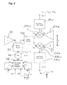
- the Fig. 2 illustrates further design details of the Doppler RF unit 12 in Fig. 1 , As in Fig. 2 Shown radiates a high-frequency transmission antenna 34 (in Fig. 1 not shown) the processed by a local oscillator 36 and a downstream power division stage 32 transmission signal in the detection range 22 from.
- the oscillator signal 36 is also suitably square-modulated by an upstream modulator unit 38, for the realization of the respective intermediate frequency pattern 1 and 2.
- the local oscillator signal is also coupled via a further power divider 40 in the channel-specific mixing stages 14b and 16b.
- an input TUN of the modulator unit 38 receives a square-wave modulated signal which causes a corresponding switching between a first frequency f 1 and a second frequency f 2 for the outputs OUT A and OUT B, in accordance with this square modulation of the period Ts.
- the (adjacent) frequencies f 1 and f 2 can be adjusted by the trimmers R 1 and R 2 shown.
- the period T s is 1 ms in the illustrated embodiment. According to the rectangular modulation, cf.
- the Doppler signal U A1 or U A2 is formed in a half period T 2/2 , as described in the appendix in Table 3.1 for the intermediate frequency signals IF A1 and IF A2 . Since the frequencies f 1 and f 2 are close to each other (and fall in the practical example only about 0.17%) can be, see. Formula 3.5, simplifying the Doppler frequency.
- the phase of the modulated Doppler signal IF A1 depends, as shown, on the distance R A of the target from the antenna 14a and on the frequency f 1 , whereas the phase of the Doppler signal IF A2 depends on R A and f 2 . Accordingly, from the difference of the phases of the signals IF A1 and IF A2, the distance R A of the target can be determined (Formula 3.15). In an analogous manner, the mixing stage 16m is moved with the Doppler signals U B1 and U B2 , corresponding to the associated intermediate frequency signals IF B1 and IF B2 .
- the Fig. 2 illustrates corresponding to the respective preparation or composition of the intermediate frequency signals IF A1 and IF A2 for the first channel and IF B1 and IF B2 for the second receiving channel. It is also shown that the receiving antennas 14a and 16a are spaced apart by a small distance S (approximately 2.5 cm in the illustrated embodiment) in the aperture area (relative to the detection distance). Also, for further processing and evaluation of these high frequency signals or their demodulated intermediate frequency signals reference is made to the description appendix, which in addition hereinafter with reference to the Fig. 3 is explained in addition.
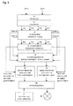
- the Fig. 3 illustrates the schematic realization of the signal processing unit 18 according to Fig. 1 comprising the Doppler radio frequency unit (according to Fig. 2 ) present signals OUT A and OUT B are present.
- These intermediate-frequency signals are first digitized in an A / D converter unit 44 and subsequently spectrally analyzed or suitably demodulated in a spectral analysis unit 48 and a (preceding) Doppler demodulation unit 46.
- the analog signals OUT A and OUT B having the sampling time T s / 2 in the middle of the half period of the signal TUN (FIG. Fig. 2 ).
- the respective sections of signal OUT A and OUT B are distributed to the Doppler signals U A1 and U A2 or U B1 and U B2 , wherein the (modulated) Doppler signals are defined with maximum amplitude.
- This maximum spectral component is searched for by the spectral analysis unit 48, for example using the so-called Görtzel algorithm (formulas 6.1 to 6.3 in the appended note), each spectral component being determined by its frequency, amplitude and phase. Because the modulated Doppler signals must have the same frequency F, this frequency is determined as the average of the frequencies of the maximum spectral components.
- the statistical evaluation unit 60 determines the variances between the applied signals.
- the formulas 7.1 to 7.15 in the description appendix explain the operation of the Kalman filters, wherein for each step a measured value is compared with the extrapolated value from a previous step, then in turn the most probable value is determined as the value with the greatest accuracy.
- the coordinates of the detection object (target) 20 resulting as a result of these filter processes are transferred to a decision unit 80 for activation of the lamp unit 10, wherein criteria (such as twilight and / or ambient brightness threshold values, minimum threshold values) that are suitably adjustable at a parameter or threshold unit 90 are provided Duty cycle or the like) are suitably preselected. Also, a maximum distance od. Like. Preselected by appropriate setting.
- the Fig. 1 realized as a sensor wall lamp with integrated into the common housing lamp device 10, which further preferably two (up and up) offers light exit surfaces and in the described embodiment, the aperture plane for the detection area for generating a horizontal detection range is formed vertically.
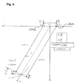
- an effective detection range distances N 1 , N 2 from the housing
- 1 m as a minimum distance
- 6 m 6 m as the maximum distance
- a definite maximum distance according to formula 4.6 (Description) depends on the difference of the frequencies f 1 and f 2 and these frequencies are set in the range between 5 MHz and 8 MHz, maximum distances between about 10 m and 15 m can be achieved.
- the target's radial velocity should be in the range between about 9.1 m / s and 1.2 m / s.
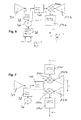
- Fig. 5 in this respect analogous to Fig. 2 ) variant of the invention provides that only the distance and distance change signal is generated.
- This variant is particularly suitable for an application context in which these detection variables are sufficient for a desired detector purpose.
- this variant of the invention which on the same constructive and signal evaluation principle as the embodiment of the Fig. 1 to 4 , based, only one channel, so far in this variant, the representation of Fig. 2 With a pair of antennas or upstream mixers shown configuration reduced to one antenna and mixer, although nevertheless this variant is then also controlled or mixed with the (square-wave modulated) stepped varied local oscillator signal.
- the representation of Fig. 6 is in this respect analogous to Fig. 3 ,
- the intermediate-frequency signal OUT (FIG. Figure 5 ) would be generated and used after demodulation ( Fig. 6 , Unit 46 ') and the spectral analysis (unit 48') intermediate frequency signals IF 1 and IF 2, further illustrated by the table 3.1 in section 8.
- the phase of the Doppler signal IF 1 is dependent on the distance R of the target from the (here single) antenna 14 and the frequency f 1
- the phase of the Doppler signal IF 2 is dependent on R and f 2 .
- This relationship makes it possible (see Formula 3.7 in Section 8), from the Phase difference to determine the distance R of the target, reference being made for further explanation to the section "8. Isolated determination of distance and distance change" and the further analysis for uniqueness, signal analysis and filtering analogous to the two-channel solution according to Fig. 1 to 4 be valid.
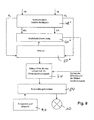
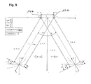
- the (isolated) determination of azimuth angle or angle change implements the two-channel realization Fig. 7 , as far as analog Fig. 2 preceded by, in departure from the solution according to the first embodiment, no variation of the frequency of the local oscillator (mutually adjacent frequencies) is necessary, but rather takes place here a simplified realization of the high-frequency module, as in Fig. 7 shown in analogy to Fig. 2 designated functional components.
- corresponding intermediate frequency signals OUT A and OUT B are produced as receiver-side mixer products, which are treated in the attached manner in accordance with Section "9.
- Isolated determination of azimuth angle and angle change" Fig. 8 and Fig. 9 for this variant, again the signal analysis and downstream filtering analogous to the first described embodiment of Fig. 1 to 4 he follows.
- Measured signals are labeled on OUT A as u A and on OUT B as u B.
- the signals u PQ are replaced by the model IF PQ and noise w .
- u PQ i IF PQ i + w i
- t ⁇ 0 PQ ⁇ 2 - ⁇ PQ 2 ⁇ ⁇ F
- F PQ k PQ 32 ⁇ T
- F 1 4 ⁇ F A ⁇ 1 + F A ⁇ 2 + F B ⁇ 1 + F B ⁇ 2
- D [w V ] of the radial velocity is calculated.
- the destination is determined if
- the spectral components are calculated by the Görtzel algorithm.
- the component becomes like the output sample IIR (Infiniti Impulse Response) of the linear system in time N.
- the searched spectral line X [k] is the Nth sample of the series y k [N] for any real k .
- s n x n + 2 ⁇ cos 2 ⁇ ⁇ k N ⁇ s ⁇ n - 1 - s ⁇ n - 2
- ⁇ P n ⁇ ⁇ A ⁇ ⁇ P ⁇ n - 1 ⁇ + ⁇ b n ⁇ + ⁇ q n ⁇ ⁇ A ⁇ ... ... Transition matrix .
- Known vector . with us ⁇ b n ⁇ ⁇ 0 0 ⁇ q n ⁇ ... ... white random process .
- the accuracy is by covariant matrix of the error of the extrapolated estimate for the time T from the last measurement.
- ⁇ B - ⁇ A 2 ⁇ ⁇ ⁇ s ⁇ f c ⁇ sin ⁇ + ⁇ + ⁇ B - ⁇ A
Landscapes
- Engineering & Computer Science (AREA)
- Radar, Positioning & Navigation (AREA)
- Remote Sensing (AREA)
- Computer Networks & Wireless Communication (AREA)
- Physics & Mathematics (AREA)
- General Physics & Mathematics (AREA)
- Radar Systems Or Details Thereof (AREA)
Applications Claiming Priority (1)
| Application Number | Priority Date | Filing Date | Title |
|---|---|---|---|
| DE102012103177.0A DE102012103177B4 (de) | 2012-04-12 | 2012-04-12 | Außensensorvorrichtung sowie Bewegungssensor-gesteuerte Außenleuchte |
Publications (3)
| Publication Number | Publication Date |
|---|---|
| EP2651194A2 true EP2651194A2 (fr) | 2013-10-16 |
| EP2651194A3 EP2651194A3 (fr) | 2015-06-24 |
| EP2651194B1 EP2651194B1 (fr) | 2020-06-03 |
Family
ID=48095624
Family Applications (1)
| Application Number | Title | Priority Date | Filing Date |
|---|---|---|---|
| EP13162997.4A Active EP2651194B1 (fr) | 2012-04-12 | 2013-04-09 | Dispositif de détection extérieur et lampe extérieure commandée par un détecteur de mouvements |
Country Status (2)
| Country | Link |
|---|---|
| EP (1) | EP2651194B1 (fr) |
| DE (1) | DE102012103177B4 (fr) |
Cited By (4)
| Publication number | Priority date | Publication date | Assignee | Title |
|---|---|---|---|---|
| WO2015144405A1 (fr) | 2014-03-26 | 2015-10-01 | Steinel Gmbh | Dispositif d'éclairage commandé |
| WO2016201597A1 (fr) * | 2015-06-15 | 2016-12-22 | 李文嵩 | Lampe frontale à détection de tête |
| AT16454U1 (de) * | 2016-06-09 | 2019-10-15 | Zumtobel Lighting Gmbh | Anwesenheitsdetektion mittels Funksignalen in einem Beleuchtungssystem |
| EP4071508A1 (fr) * | 2021-04-09 | 2022-10-12 | Tridonic GmbH & Co. KG | Détecteur de mouvement pour un luminaire |
Families Citing this family (2)
| Publication number | Priority date | Publication date | Assignee | Title |
|---|---|---|---|---|
| DE102014104299A1 (de) | 2014-03-27 | 2015-10-01 | Steinel Gmbh | Bewegungssensorvorrichtung sowie Verwendung einer solchen |
| DE102016104466A1 (de) * | 2016-03-11 | 2017-09-14 | Osram Gmbh | Leuchteinrichtung |
Family Cites Families (4)
| Publication number | Priority date | Publication date | Assignee | Title |
|---|---|---|---|---|
| US8232909B2 (en) * | 2008-09-30 | 2012-07-31 | Cooper Technologies Company | Doppler radar motion detector for an outdoor light fixture |
| US8159344B2 (en) * | 2008-10-28 | 2012-04-17 | Honeywell International, Inc. | Microwave motion detectors utilizing multi-frequency ranging and target angle detection |
| US8199012B2 (en) * | 2009-02-12 | 2012-06-12 | Honeywell International Inc. | Microwave curtain sensor |
| WO2012023087A1 (fr) * | 2010-08-16 | 2012-02-23 | Koninklijke Philips Electronics N.V. | Système de radars multiples |
-
2012
- 2012-04-12 DE DE102012103177.0A patent/DE102012103177B4/de active Active
-
2013
- 2013-04-09 EP EP13162997.4A patent/EP2651194B1/fr active Active
Cited By (6)
| Publication number | Priority date | Publication date | Assignee | Title |
|---|---|---|---|---|
| WO2015144405A1 (fr) | 2014-03-26 | 2015-10-01 | Steinel Gmbh | Dispositif d'éclairage commandé |
| DE102014104174A1 (de) | 2014-03-26 | 2015-10-01 | Steinel Gmbh | Gesteuerte Leuchtenvorrichtung |
| WO2016201597A1 (fr) * | 2015-06-15 | 2016-12-22 | 李文嵩 | Lampe frontale à détection de tête |
| AT16454U1 (de) * | 2016-06-09 | 2019-10-15 | Zumtobel Lighting Gmbh | Anwesenheitsdetektion mittels Funksignalen in einem Beleuchtungssystem |
| EP4071508A1 (fr) * | 2021-04-09 | 2022-10-12 | Tridonic GmbH & Co. KG | Détecteur de mouvement pour un luminaire |
| WO2022214327A1 (fr) * | 2021-04-09 | 2022-10-13 | Tridonic Gmbh & Co Kg | Détecteur de mouvement pour un luminaire |
Also Published As
| Publication number | Publication date |
|---|---|
| DE102012103177B4 (de) | 2026-01-08 |
| DE102012103177A1 (de) | 2013-10-17 |
| EP2651194A3 (fr) | 2015-06-24 |
| EP2651194B1 (fr) | 2020-06-03 |
Similar Documents
| Publication | Publication Date | Title |
|---|---|---|
| EP2651194B1 (fr) | Dispositif de détection extérieur et lampe extérieure commandée par un détecteur de mouvements | |
| DE2613845C3 (de) | Die Dopplerverschiebung der Rflexion von elektromagnetischer und Ultraschall-Strahlung auswertendes Einbruchalarmgerät | |
| DE2002012A1 (de) | Vorrichtung und Verfahren zum Melden von Hindernissen und zur Anzeige der Entfernung der Hindernisse | |
| EP1342101A1 (fr) | Procede radar a impulsions, detecteur radar a impulsions et systeme correspondant | |
| EP2025067A1 (fr) | Émetteur radio, récepteur radio, système et procédé impliquant un émetteur radio et un récepteur radio | |
| DE102014114107A1 (de) | Radarsensor | |
| DE112017003596T5 (de) | 1 - 18Hochsicherheits-Bewegungsmelder | |
| DE10100416A1 (de) | Radareinrichtung und Verfahren zum Unterdrücken von Störungen einer Radareinrichtung | |
| DE10249866A1 (de) | Verfahren und Vorrichtung zur Positionsbestimmung wenigstens einer zweiten Sende- und Empfangseinrichtung bezüglich einer ersten Sende- und Empfangseinrichtung in einem GHz-Bereich arbeitenden passiven Zugangskontrollsystem | |
| EP3381025A1 (fr) | Procédé et dispositif de normalisation de données de signal d'écho ultrasonore | |
| EP2850739B1 (fr) | Procédé de transmission radio par transmission ultra-large bande | |
| EP1831720A1 (fr) | Systeme de radar pour la surveillance de cibles dans differentes zones de distance | |
| EP0777131A1 (fr) | Dispositif de surveillance avec une sonde radar | |
| DE102009013300A1 (de) | Funktionsmoduliertes FMCW-Radar mit Integratorempfänger | |
| DE102020107012A1 (de) | Fahrerassistenzsystem zur Erkennung fremder Signale | |
| EP3391079B1 (fr) | Détection de présence au moyen de signaux radio dans un système d'éclairage | |
| EP2465310B1 (fr) | Procédé et agencement pour la mesure de la durée de propagation d'un signal entre deux stations de l'agencement | |
| WO2018064994A1 (fr) | Procédé et dispositif de détermination de position | |
| DE2615985C2 (de) | Vorrichtung zur Meldung des Luftdruckabfalls in Fah rzeugreifen | |
| DE102017118324B4 (de) | Anordnung und Verfahren zur Abstandsmessung zwischen Geräten in einem Funksystem | |
| EP2551697B1 (fr) | Procédé de detection d'une variation d'un détecteur de présence ou de mouvements associé à une zone de surveillance | |
| EP3136124B1 (fr) | Procédé pour mettre en service des capteurs radar dans un véhicule à moteur et véhicule à moteur | |
| DE3920302C1 (de) | Radargerät | |
| DE102018122870A1 (de) | Verfahren zur Auswertung eines Radarsignals und System | |
| EP1790994A1 (fr) | Procédé de déclenchement d'un événement en réponse à un mouvement, système avec un capteur de mouvement et capteur de mouvement |
Legal Events
| Date | Code | Title | Description |
|---|---|---|---|
| PUAI | Public reference made under article 153(3) epc to a published international application that has entered the european phase |
Free format text: ORIGINAL CODE: 0009012 |
|
| AK | Designated contracting states |
Kind code of ref document: A2 Designated state(s): AL AT BE BG CH CY CZ DE DK EE ES FI FR GB GR HR HU IE IS IT LI LT LU LV MC MK MT NL NO PL PT RO RS SE SI SK SM TR |
|
| AX | Request for extension of the european patent |
Extension state: BA ME |
|
| RIC1 | Information provided on ipc code assigned before grant |
Ipc: G01S 13/56 20060101ALI20150204BHEP Ipc: H05B 37/02 20060101AFI20150204BHEP Ipc: G01S 13/86 20060101ALI20150204BHEP Ipc: G01S 7/28 20060101ALI20150204BHEP Ipc: G01S 13/38 20060101ALI20150204BHEP |
|
| PUAL | Search report despatched |
Free format text: ORIGINAL CODE: 0009013 |
|
| AK | Designated contracting states |
Kind code of ref document: A3 Designated state(s): AL AT BE BG CH CY CZ DE DK EE ES FI FR GB GR HR HU IE IS IT LI LT LU LV MC MK MT NL NO PL PT RO RS SE SI SK SM TR |
|
| AX | Request for extension of the european patent |
Extension state: BA ME |
|
| RIC1 | Information provided on ipc code assigned before grant |
Ipc: G01S 13/86 20060101ALI20150520BHEP Ipc: G01S 13/38 20060101ALI20150520BHEP Ipc: G01S 7/28 20060101ALI20150520BHEP Ipc: H05B 37/02 20060101AFI20150520BHEP Ipc: G01S 13/56 20060101ALI20150520BHEP |
|
| 17P | Request for examination filed |
Effective date: 20151223 |
|
| RBV | Designated contracting states (corrected) |
Designated state(s): AL AT BE BG CH CY CZ DE DK EE ES FI FR GB GR HR HU IE IS IT LI LT LU LV MC MK MT NL NO PL PT RO RS SE SI SK SM TR |
|
| STAA | Information on the status of an ep patent application or granted ep patent |
Free format text: STATUS: EXAMINATION IS IN PROGRESS |
|
| 17Q | First examination report despatched |
Effective date: 20170726 |
|
| GRAP | Despatch of communication of intention to grant a patent |
Free format text: ORIGINAL CODE: EPIDOSNIGR1 |
|
| STAA | Information on the status of an ep patent application or granted ep patent |
Free format text: STATUS: GRANT OF PATENT IS INTENDED |
|
| INTG | Intention to grant announced |
Effective date: 20191105 |
|
| GRAS | Grant fee paid |
Free format text: ORIGINAL CODE: EPIDOSNIGR3 |
|
| GRAA | (expected) grant |
Free format text: ORIGINAL CODE: 0009210 |
|
| STAA | Information on the status of an ep patent application or granted ep patent |
Free format text: STATUS: THE PATENT HAS BEEN GRANTED |
|
| AK | Designated contracting states |
Kind code of ref document: B1 Designated state(s): AL AT BE BG CH CY CZ DE DK EE ES FI FR GB GR HR HU IE IS IT LI LT LU LV MC MK MT NL NO PL PT RO RS SE SI SK SM TR |
|
| REG | Reference to a national code |
Ref country code: GB Ref legal event code: FG4D Free format text: NOT ENGLISH |
|
| REG | Reference to a national code |
Ref country code: CH Ref legal event code: EP Ref country code: AT Ref legal event code: REF Ref document number: 1278464 Country of ref document: AT Kind code of ref document: T Effective date: 20200615 |
|
| REG | Reference to a national code |
Ref country code: DE Ref legal event code: R096 Ref document number: 502013014752 Country of ref document: DE |
|
| REG | Reference to a national code |
Ref country code: LT Ref legal event code: MG4D |
|
| PG25 | Lapsed in a contracting state [announced via postgrant information from national office to epo] |
Ref country code: SE Free format text: LAPSE BECAUSE OF FAILURE TO SUBMIT A TRANSLATION OF THE DESCRIPTION OR TO PAY THE FEE WITHIN THE PRESCRIBED TIME-LIMIT Effective date: 20200603 Ref country code: NO Free format text: LAPSE BECAUSE OF FAILURE TO SUBMIT A TRANSLATION OF THE DESCRIPTION OR TO PAY THE FEE WITHIN THE PRESCRIBED TIME-LIMIT Effective date: 20200903 Ref country code: FI Free format text: LAPSE BECAUSE OF FAILURE TO SUBMIT A TRANSLATION OF THE DESCRIPTION OR TO PAY THE FEE WITHIN THE PRESCRIBED TIME-LIMIT Effective date: 20200603 Ref country code: GR Free format text: LAPSE BECAUSE OF FAILURE TO SUBMIT A TRANSLATION OF THE DESCRIPTION OR TO PAY THE FEE WITHIN THE PRESCRIBED TIME-LIMIT Effective date: 20200904 Ref country code: LT Free format text: LAPSE BECAUSE OF FAILURE TO SUBMIT A TRANSLATION OF THE DESCRIPTION OR TO PAY THE FEE WITHIN THE PRESCRIBED TIME-LIMIT Effective date: 20200603 |
|
| REG | Reference to a national code |
Ref country code: NL Ref legal event code: MP Effective date: 20200603 |
|
| PG25 | Lapsed in a contracting state [announced via postgrant information from national office to epo] |
Ref country code: HR Free format text: LAPSE BECAUSE OF FAILURE TO SUBMIT A TRANSLATION OF THE DESCRIPTION OR TO PAY THE FEE WITHIN THE PRESCRIBED TIME-LIMIT Effective date: 20200603 Ref country code: RS Free format text: LAPSE BECAUSE OF FAILURE TO SUBMIT A TRANSLATION OF THE DESCRIPTION OR TO PAY THE FEE WITHIN THE PRESCRIBED TIME-LIMIT Effective date: 20200603 Ref country code: LV Free format text: LAPSE BECAUSE OF FAILURE TO SUBMIT A TRANSLATION OF THE DESCRIPTION OR TO PAY THE FEE WITHIN THE PRESCRIBED TIME-LIMIT Effective date: 20200603 Ref country code: BG Free format text: LAPSE BECAUSE OF FAILURE TO SUBMIT A TRANSLATION OF THE DESCRIPTION OR TO PAY THE FEE WITHIN THE PRESCRIBED TIME-LIMIT Effective date: 20200903 |
|
| PG25 | Lapsed in a contracting state [announced via postgrant information from national office to epo] |
Ref country code: NL Free format text: LAPSE BECAUSE OF FAILURE TO SUBMIT A TRANSLATION OF THE DESCRIPTION OR TO PAY THE FEE WITHIN THE PRESCRIBED TIME-LIMIT Effective date: 20200603 Ref country code: AL Free format text: LAPSE BECAUSE OF FAILURE TO SUBMIT A TRANSLATION OF THE DESCRIPTION OR TO PAY THE FEE WITHIN THE PRESCRIBED TIME-LIMIT Effective date: 20200603 |
|
| PG25 | Lapsed in a contracting state [announced via postgrant information from national office to epo] |
Ref country code: PT Free format text: LAPSE BECAUSE OF FAILURE TO SUBMIT A TRANSLATION OF THE DESCRIPTION OR TO PAY THE FEE WITHIN THE PRESCRIBED TIME-LIMIT Effective date: 20201006 Ref country code: IT Free format text: LAPSE BECAUSE OF FAILURE TO SUBMIT A TRANSLATION OF THE DESCRIPTION OR TO PAY THE FEE WITHIN THE PRESCRIBED TIME-LIMIT Effective date: 20200603 Ref country code: RO Free format text: LAPSE BECAUSE OF FAILURE TO SUBMIT A TRANSLATION OF THE DESCRIPTION OR TO PAY THE FEE WITHIN THE PRESCRIBED TIME-LIMIT Effective date: 20200603 Ref country code: EE Free format text: LAPSE BECAUSE OF FAILURE TO SUBMIT A TRANSLATION OF THE DESCRIPTION OR TO PAY THE FEE WITHIN THE PRESCRIBED TIME-LIMIT Effective date: 20200603 Ref country code: SM Free format text: LAPSE BECAUSE OF FAILURE TO SUBMIT A TRANSLATION OF THE DESCRIPTION OR TO PAY THE FEE WITHIN THE PRESCRIBED TIME-LIMIT Effective date: 20200603 Ref country code: CZ Free format text: LAPSE BECAUSE OF FAILURE TO SUBMIT A TRANSLATION OF THE DESCRIPTION OR TO PAY THE FEE WITHIN THE PRESCRIBED TIME-LIMIT Effective date: 20200603 Ref country code: ES Free format text: LAPSE BECAUSE OF FAILURE TO SUBMIT A TRANSLATION OF THE DESCRIPTION OR TO PAY THE FEE WITHIN THE PRESCRIBED TIME-LIMIT Effective date: 20200603 |
|
| PG25 | Lapsed in a contracting state [announced via postgrant information from national office to epo] |
Ref country code: SK Free format text: LAPSE BECAUSE OF FAILURE TO SUBMIT A TRANSLATION OF THE DESCRIPTION OR TO PAY THE FEE WITHIN THE PRESCRIBED TIME-LIMIT Effective date: 20200603 Ref country code: PL Free format text: LAPSE BECAUSE OF FAILURE TO SUBMIT A TRANSLATION OF THE DESCRIPTION OR TO PAY THE FEE WITHIN THE PRESCRIBED TIME-LIMIT Effective date: 20200603 Ref country code: IS Free format text: LAPSE BECAUSE OF FAILURE TO SUBMIT A TRANSLATION OF THE DESCRIPTION OR TO PAY THE FEE WITHIN THE PRESCRIBED TIME-LIMIT Effective date: 20201003 |
|
| REG | Reference to a national code |
Ref country code: DE Ref legal event code: R097 Ref document number: 502013014752 Country of ref document: DE |
|
| PLBE | No opposition filed within time limit |
Free format text: ORIGINAL CODE: 0009261 |
|
| STAA | Information on the status of an ep patent application or granted ep patent |
Free format text: STATUS: NO OPPOSITION FILED WITHIN TIME LIMIT |
|
| PG25 | Lapsed in a contracting state [announced via postgrant information from national office to epo] |
Ref country code: DK Free format text: LAPSE BECAUSE OF FAILURE TO SUBMIT A TRANSLATION OF THE DESCRIPTION OR TO PAY THE FEE WITHIN THE PRESCRIBED TIME-LIMIT Effective date: 20200603 |
|
| 26N | No opposition filed |
Effective date: 20210304 |
|
| PG25 | Lapsed in a contracting state [announced via postgrant information from national office to epo] |
Ref country code: SI Free format text: LAPSE BECAUSE OF FAILURE TO SUBMIT A TRANSLATION OF THE DESCRIPTION OR TO PAY THE FEE WITHIN THE PRESCRIBED TIME-LIMIT Effective date: 20200603 |
|
| PG25 | Lapsed in a contracting state [announced via postgrant information from national office to epo] |
Ref country code: MC Free format text: LAPSE BECAUSE OF FAILURE TO SUBMIT A TRANSLATION OF THE DESCRIPTION OR TO PAY THE FEE WITHIN THE PRESCRIBED TIME-LIMIT Effective date: 20200603 |
|
| PG25 | Lapsed in a contracting state [announced via postgrant information from national office to epo] |
Ref country code: LU Free format text: LAPSE BECAUSE OF NON-PAYMENT OF DUE FEES Effective date: 20210409 |
|
| REG | Reference to a national code |
Ref country code: BE Ref legal event code: MM Effective date: 20210430 |
|
| PG25 | Lapsed in a contracting state [announced via postgrant information from national office to epo] |
Ref country code: LI Free format text: LAPSE BECAUSE OF NON-PAYMENT OF DUE FEES Effective date: 20210430 Ref country code: CH Free format text: LAPSE BECAUSE OF NON-PAYMENT OF DUE FEES Effective date: 20210430 |
|
| PG25 | Lapsed in a contracting state [announced via postgrant information from national office to epo] |
Ref country code: IE Free format text: LAPSE BECAUSE OF NON-PAYMENT OF DUE FEES Effective date: 20210409 |
|
| PG25 | Lapsed in a contracting state [announced via postgrant information from national office to epo] |
Ref country code: IS Free format text: LAPSE BECAUSE OF FAILURE TO SUBMIT A TRANSLATION OF THE DESCRIPTION OR TO PAY THE FEE WITHIN THE PRESCRIBED TIME-LIMIT Effective date: 20201003 |
|
| REG | Reference to a national code |
Ref country code: AT Ref legal event code: MM01 Ref document number: 1278464 Country of ref document: AT Kind code of ref document: T Effective date: 20210409 |
|
| PG25 | Lapsed in a contracting state [announced via postgrant information from national office to epo] |
Ref country code: BE Free format text: LAPSE BECAUSE OF NON-PAYMENT OF DUE FEES Effective date: 20210430 |
|
| PG25 | Lapsed in a contracting state [announced via postgrant information from national office to epo] |
Ref country code: AT Free format text: LAPSE BECAUSE OF NON-PAYMENT OF DUE FEES Effective date: 20210409 |
|
| PG25 | Lapsed in a contracting state [announced via postgrant information from national office to epo] |
Ref country code: HU Free format text: LAPSE BECAUSE OF FAILURE TO SUBMIT A TRANSLATION OF THE DESCRIPTION OR TO PAY THE FEE WITHIN THE PRESCRIBED TIME-LIMIT; INVALID AB INITIO Effective date: 20130409 |
|
| P01 | Opt-out of the competence of the unified patent court (upc) registered |
Effective date: 20230512 |
|
| PG25 | Lapsed in a contracting state [announced via postgrant information from national office to epo] |
Ref country code: CY Free format text: LAPSE BECAUSE OF FAILURE TO SUBMIT A TRANSLATION OF THE DESCRIPTION OR TO PAY THE FEE WITHIN THE PRESCRIBED TIME-LIMIT Effective date: 20200603 |
|
| PG25 | Lapsed in a contracting state [announced via postgrant information from national office to epo] |
Ref country code: MK Free format text: LAPSE BECAUSE OF FAILURE TO SUBMIT A TRANSLATION OF THE DESCRIPTION OR TO PAY THE FEE WITHIN THE PRESCRIBED TIME-LIMIT Effective date: 20200603 |
|
| REG | Reference to a national code |
Ref country code: DE Ref legal event code: R082 Ref document number: 502013014752 Country of ref document: DE Representative=s name: MATHYS & SQUIRE EUROPE PATENTANWAELTE PARTNERS, DE |
|
| PG25 | Lapsed in a contracting state [announced via postgrant information from national office to epo] |
Ref country code: TR Free format text: LAPSE BECAUSE OF FAILURE TO SUBMIT A TRANSLATION OF THE DESCRIPTION OR TO PAY THE FEE WITHIN THE PRESCRIBED TIME-LIMIT Effective date: 20200603 |
|
| PG25 | Lapsed in a contracting state [announced via postgrant information from national office to epo] |
Ref country code: MT Free format text: LAPSE BECAUSE OF FAILURE TO SUBMIT A TRANSLATION OF THE DESCRIPTION OR TO PAY THE FEE WITHIN THE PRESCRIBED TIME-LIMIT Effective date: 20200603 |
|
| PGFP | Annual fee paid to national office [announced via postgrant information from national office to epo] |
Ref country code: DE Payment date: 20250414 Year of fee payment: 13 |
|
| PGFP | Annual fee paid to national office [announced via postgrant information from national office to epo] |
Ref country code: GB Payment date: 20250429 Year of fee payment: 13 |
|
| PGFP | Annual fee paid to national office [announced via postgrant information from national office to epo] |
Ref country code: FR Payment date: 20250428 Year of fee payment: 13 |