EP2653311A2 - Dispositif de découpage à coupure variable - Google Patents
Dispositif de découpage à coupure variable Download PDFInfo
- Publication number
- EP2653311A2 EP2653311A2 EP20130164106 EP13164106A EP2653311A2 EP 2653311 A2 EP2653311 A2 EP 2653311A2 EP 20130164106 EP20130164106 EP 20130164106 EP 13164106 A EP13164106 A EP 13164106A EP 2653311 A2 EP2653311 A2 EP 2653311A2
- Authority
- EP
- European Patent Office
- Prior art keywords
- cylinder
- cutting
- web
- knife
- anvil
- Prior art date
- Legal status (The legal status is an assumption and is not a legal conclusion. Google has not performed a legal analysis and makes no representation as to the accuracy of the status listed.)
- Granted
Links
Images
Classifications
-
- B—PERFORMING OPERATIONS; TRANSPORTING
- B41—PRINTING; LINING MACHINES; TYPEWRITERS; STAMPS
- B41F—PRINTING MACHINES OR PRESSES
- B41F13/00—Common details of rotary presses or machines
- B41F13/54—Auxiliary folding, cutting, collecting or depositing of sheets or webs
- B41F13/56—Folding or cutting
- B41F13/58—Folding or cutting lengthwise
-
- B—PERFORMING OPERATIONS; TRANSPORTING
- B65—CONVEYING; PACKING; STORING; HANDLING THIN OR FILAMENTARY MATERIAL
- B65H—HANDLING THIN OR FILAMENTARY MATERIAL, e.g. SHEETS, WEBS, CABLES
- B65H35/00—Delivering articles from cutting or line-perforating machines; Article or web delivery apparatus incorporating cutting or line-perforating devices, e.g. adhesive tape dispensers
- B65H35/04—Delivering articles from cutting or line-perforating machines; Article or web delivery apparatus incorporating cutting or line-perforating devices, e.g. adhesive tape dispensers from or with transverse cutters or perforators
- B65H35/08—Delivering articles from cutting or line-perforating machines; Article or web delivery apparatus incorporating cutting or line-perforating devices, e.g. adhesive tape dispensers from or with transverse cutters or perforators from or with revolving, e.g. cylinder, cutters or perforators
-
- B—PERFORMING OPERATIONS; TRANSPORTING
- B26—HAND CUTTING TOOLS; CUTTING; SEVERING
- B26D—CUTTING; DETAILS COMMON TO MACHINES FOR PERFORATING, PUNCHING, CUTTING-OUT, STAMPING-OUT OR SEVERING
- B26D1/00—Cutting through work characterised by the nature or movement of the cutting member or particular materials not otherwise provided for; Apparatus or machines therefor; Cutting members therefor
- B26D1/01—Cutting through work characterised by the nature or movement of the cutting member or particular materials not otherwise provided for; Apparatus or machines therefor; Cutting members therefor involving a cutting member which does not travel with the work
- B26D1/12—Cutting through work characterised by the nature or movement of the cutting member or particular materials not otherwise provided for; Apparatus or machines therefor; Cutting members therefor involving a cutting member which does not travel with the work having a cutting member moving about an axis
- B26D1/25—Cutting through work characterised by the nature or movement of the cutting member or particular materials not otherwise provided for; Apparatus or machines therefor; Cutting members therefor involving a cutting member which does not travel with the work having a cutting member moving about an axis with a non-circular cutting member
- B26D1/34—Cutting through work characterised by the nature or movement of the cutting member or particular materials not otherwise provided for; Apparatus or machines therefor; Cutting members therefor involving a cutting member which does not travel with the work having a cutting member moving about an axis with a non-circular cutting member moving about an axis parallel to the line of cut
- B26D1/40—Cutting through work characterised by the nature or movement of the cutting member or particular materials not otherwise provided for; Apparatus or machines therefor; Cutting members therefor involving a cutting member which does not travel with the work having a cutting member moving about an axis with a non-circular cutting member moving about an axis parallel to the line of cut and coacting with a rotary member
- B26D1/405—Cutting through work characterised by the nature or movement of the cutting member or particular materials not otherwise provided for; Apparatus or machines therefor; Cutting members therefor involving a cutting member which does not travel with the work having a cutting member moving about an axis with a non-circular cutting member moving about an axis parallel to the line of cut and coacting with a rotary member for thin material, e.g. for sheets, strips or the like
-
- B—PERFORMING OPERATIONS; TRANSPORTING
- B26—HAND CUTTING TOOLS; CUTTING; SEVERING
- B26D—CUTTING; DETAILS COMMON TO MACHINES FOR PERFORATING, PUNCHING, CUTTING-OUT, STAMPING-OUT OR SEVERING
- B26D5/00—Arrangements for operating and controlling machines or devices for cutting, cutting-out, stamping-out, punching, perforating, or severing by means other than cutting
- B26D5/02—Means for moving the cutting member into its operative position for cutting
-
- B—PERFORMING OPERATIONS; TRANSPORTING
- B41—PRINTING; LINING MACHINES; TYPEWRITERS; STAMPS
- B41F—PRINTING MACHINES OR PRESSES
- B41F13/00—Common details of rotary presses or machines
- B41F13/54—Auxiliary folding, cutting, collecting or depositing of sheets or webs
- B41F13/56—Folding or cutting
- B41F13/60—Folding or cutting crosswise
-
- B—PERFORMING OPERATIONS; TRANSPORTING
- B41—PRINTING; LINING MACHINES; TYPEWRITERS; STAMPS
- B41F—PRINTING MACHINES OR PRESSES
- B41F13/00—Common details of rotary presses or machines
- B41F13/54—Auxiliary folding, cutting, collecting or depositing of sheets or webs
- B41F13/56—Folding or cutting
- B41F13/62—Folding-cylinders or drums
-
- Y—GENERAL TAGGING OF NEW TECHNOLOGICAL DEVELOPMENTS; GENERAL TAGGING OF CROSS-SECTIONAL TECHNOLOGIES SPANNING OVER SEVERAL SECTIONS OF THE IPC; TECHNICAL SUBJECTS COVERED BY FORMER USPC CROSS-REFERENCE ART COLLECTIONS [XRACs] AND DIGESTS
- Y10—TECHNICAL SUBJECTS COVERED BY FORMER USPC
- Y10T—TECHNICAL SUBJECTS COVERED BY FORMER US CLASSIFICATION
- Y10T83/00—Cutting
- Y10T83/04—Processes
- Y10T83/05—With reorientation of tool between cuts
-
- Y—GENERAL TAGGING OF NEW TECHNOLOGICAL DEVELOPMENTS; GENERAL TAGGING OF CROSS-SECTIONAL TECHNOLOGIES SPANNING OVER SEVERAL SECTIONS OF THE IPC; TECHNICAL SUBJECTS COVERED BY FORMER USPC CROSS-REFERENCE ART COLLECTIONS [XRACs] AND DIGESTS
- Y10—TECHNICAL SUBJECTS COVERED BY FORMER USPC
- Y10T—TECHNICAL SUBJECTS COVERED BY FORMER US CLASSIFICATION
- Y10T83/00—Cutting
- Y10T83/465—Cutting motion of tool has component in direction of moving work
- Y10T83/4766—Orbital motion of cutting blade
- Y10T83/4795—Rotary tool
- Y10T83/483—With cooperating rotary cutter or backup
- Y10T83/4838—With anvil backup
Definitions
- the present invention relates generally to printing press equipment and more particularly to cutting devices and cutting folders.
- U.S. 5,865,082 discloses a first conveyor assembly and a second conveyor assembly.
- Cooperating cutting cylinders having a knife and an anvil are integrated into paths of the conveying elements of the first and second conveyor assemblies, seizing a web of material prior to a cutting operation.
- U.S. 6,684,746 discloses cutting a web by linearly moving a plurality of cutting elements in a same direction as web in a signature formation area and cutting the web with the cutting elements to form signatures. A length of the signatures is varied by varying the spacing between the cutting elements in the signature formation area.
- U.S. 8,104,755 discloses an adjustable delivery web conversion apparatus.
- a variable cutoff printing unit prints pages on a web is slit into ribbons.
- a cutting apparatus cuts the ribbons into signatures.
- a controller controls the cutting apparatus based on the printing by the variable cutoff printing unit so the pages are properly positioned on the signatures.
- An object of the present invention provides discrete cut length changes of a product by sliding cutting cylinders sets of different diameters and/or knife arrangements into and out of the web path in a folder. This allows the production of 203 mm, 244 mm and 305 mm products from a 1220 mm blanket circumference.
- Another object of the present invention provides cutting cylinder sets which can change speeds relative to the web in order to produce discrete sizes within a 10 mm range. For example, product lengths varying between 305 mm and 315 mm may be cut by rotating the 315 mm size cutting cylinder set faster relative to the web speed.
- the present invention provides a folder for a printing press including: a cutting cylinder assembly having at least two knife and anvil cylinder sets positioned near the cutting region of a folder.
- the cutting cylinder assembly slides or actuates one of the knife and anvil cylinder sets into a cutting position for a desired cut length.
- the web passes between the knife and anvil cylinder set and is cut.
- the assembly is relocated to such a position that a second or further set of knife and anvil cylinders is aligned with the web.
- a folder for a printing press includes a movable assembly which includes a first cutting cylinder pair including a first knife cylinder and a first anvil cylinder for cutting a web into signatures, and a second cutting cylinder pair including a second knife cylinder and a second anvil cylinder for cutting the web into signatures.
- the movable assembly supports the first cutting cylinder pair and second cutting cylinder pair, and the assembly is movable to selectively position either the first cutting cylinder pair or the second cutting cylinder pair into a cutting position for cutting the web.
- the aforementioned embodiment may also include other optional components and features.
- the following features may be included, in any combination:
- the movable assembly maybe movable perpendicular to a transport path of the web.
- the folder may include one or more rails, and wherein the movable assembly is movable perpendicular to a transport path of the web on the one or more rails.
- a linear bearing or bushing may be provided, wherein the movable assembly is movable perpendicular to a transport path of the web via the linear bearing or bushing.
- an actuator is coupled to the movable assembly, the actuator moving the movable assembly to selectively position either the first cutting cylinder pair or the second cutting cylinder pair into a cutting position for cutting the web.
- the actuator may, for example, be one of a hydraulic actuator, a pneumatic actuator, and a motor.
- a former provided upstream of the movable assembly, is arranged to impart a longitudinal fold to a web.
- a plurality of guide belts is provided downstream of the movable assembly, the plurality of guide belts are arranged to receive the cut web from the movable assembly, and the moveable assembly is movable perpendicular to a web path of the web.
- the first knife cylinder includes a first, second, third and fourth knife box positions, the first and third knife box positions equally spaced apart from each other around a circumference of the first knife cylinder.
- the first, second, and fourth knife box positions are equally spaced apart from each other around the circumference.
- the first anvil cylinder may include a first, second, third and fourth anvil positions, the first and third anvil positions equally spaced apart from each other around a circumference of the first anvil cylinder, and the first, second, and fourth anvil positions equally spaced apart from each other around the circumference.
- the second knife cylinder may include a first knife box and a second knife box equally spaced apart from each other around a circumference of the second knife cylinder
- the second anvil cylinder may include a first anvil and a second anvil equally spaced apart from each other around a circumference of the second anvil cylinder
- the first and third knife box positions may each have removably secured therein a knife box, while in the remaining knife box positions no knife box may be present
- the first and third anvil positions may each have removably secured therein an anvil, while in the remaining anvil positions no anvil may be present, so that the first cutting cylinder pair provides, in particular exclusively, four cuts for each revolution of a plate cylinder of the printing press.
- the first, second and fourth knife box positions may each have removably secured therein a knife box
- the first, second and fourth anvil positions may each have removably secured therein an anvil.
- a filler piece can be provided in anvil or knife box positions when no anvil or knife box is present.
- a method of cutting a web into variable length signatures includes the steps of: (a) supporting a first cutting cylinder pair and a second cutting cylinder pair with an assembly; (b) positioning either the first cutting cylinder pair or second cutting cylinder pair into a cutting position with respect to the web; (c) cutting the web into signatures using the positioned cylinder pair; (d) repositioning the first and/or second cylinder pairs so the other cutting pair is in a cutting position with respect to the web; and (e) cutting the web into signatures using the other positioned cylinder pair.
- the aforementioned embodiment may also include other optional steps. For example, the following additional steps may be included:
- the step of positioning includes moving the assembly perpendicular to a transport path of the web.
- the step of cutting the web into signatures using the positioned cylinder pair includes providing, in particular exclusively, four cuts per revolution of a plate cylinder of a printing press located upstream of the assembly.
- the step of cutting the web into signatures using the positioned cylinder pair includes providing, in particular exclusively, six cuts per revolution of a plate cylinder of a printing press located upstream of the assembly.
- the step of cutting the web into signatures using the other positioned cylinder pair includes providing, in particular exclusively, five cuts per revolution of the plate cylinder of the printing press located upstream of the assembly.
- the method comprises, after either step (c) or step (e): (f) cutting the web into signatures using the positioned cylinder pair, the positioned cylinder pair providing, in particular exclusively, six cuts per revolution of the plate cylinder of the printing press located upstream of the assembly.
- the first knife cylinder may include a first, second, third and fourth knife box positions, where the first and third knife box positions are equally spaced apart from each other around a circumference of the first knife cylinder, and the first, second, and fourth knife box positions are equally spaced apart from each other around the circumference.
- the first and third knife box positions each have removably secured therein a knife box, while in the remaining knife box positions no knife box may be present, and before step (f), the method may include removing the knife box from the third knife position, and removably securing in each of the second and fourth knife positions a respective knife box.
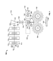
- Fig. 1 shows a schematic representation of a printing press including a cutting folder according to the present invention.
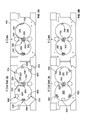
- Figure 2a illustrates the cutting assembly of the folder of Figure 1 configured to provide 4 or 5 cuts per plate cylinder revolution
- Figure 2b illustrates the cutting assembly of the folder of Figure 1 configured to provide 6 or 5 cuts per plate cylinder revolution.
- Fig. 1 shows a schematic representation of a printing press including a folder in accordance with the present invention.
- Printing press 100 may be, for example, a four color web offset printing press.
- Printing units 112 may each include two print couples, each couple including a plate cylinder 113 and a blanket cylinder 114. Each couple prints on either side of a web 101.
- Each print unit 112 may print a different a color, for example, magenta, cyan, yellow or black.
- web 101 may be slit into a plurality of ribbons by a slitter 116, if desired.
- the ribbons may be combined and transported to a former 120 for longitudinal folding.
- the former fold 122 is in line with a direction of travel A of web 101.
- Printing press 100 may include a folder 110 for folding, cutting and processing web 101 into signatures 102.
- Folder 110 may be a pinless former folder, for example.
- Cutting section 128 may include an assembly 140 supporting two pairs of cutting cylinders 136, 146.
- Each cutting cylinder pair 136, 146 includes a respective knife cylinder 132, 142 and a corresponding anvil cylinder 134, 144.
- the assembly 140 is positioned with respect to web 101 so either first cutting cylinder pair 136 or second cutting cylinder pair 146 is in a cutting position with respect to web 101.
- first cutting cylinder pair 136 is in position with respect to web 101.
- the dashed line outlines a second position of assembly 140 which would align second cutting cylinder pair 146 into a cutting position with respect to web 101.
- Cutting cylinder pair 136 may include, for example, three knives and cut web 101 into signatures have a length of 203.33 mm each.
- Second knife cylinder 142 may have a different diameter than first cutting cylinder 132 and may include two or three knives, for example.
- Anvil cylinders 134, 144 include cutting rubbers for the knives to cut against.
- Knife cylinders 132, 142 may be designed to accommodate a number of knives.
- knife cylinders 132, 142 may include four knife box positions. However, for a specific cutting job, only two knife box positions may include knives. The other two knife box positions may include a filler piece. For a subsequent cutting job, one or both of the filler pieces may be removed and additional knives may be installed.
- knife cylinders 132, 142 may support two equally spaced knives or three equally spaced knives for example.
- cutting cylinder pair 136 may be configured to provide an even number of cuts per plate cylinder revolution whereas cutting cylinder pair 146 may be configured to provide an odd number of cuts per plate cylinder revolution.
- cylinder pair 136 may be configured with different numbers of cutting knives/anvil rubbers to provide further variability.
- cutting cylinder 132 may be configured to hold 2 knife boxes equally spaced apart around the cutting cylinder circumference to provide 4 cuts per plate cylinder revolution, and may be configured to hold 3 knife boxes equally spaced apart around the cutting cylinder circumference to provide 6 cuts per plate cylinder revolution.
- Cutting cylinder pair 146 may be configured to provide 5 cut per plate cylinder revolution.
- Figures 2(a) and 2(b) shows cutting cylinder pair 136 configured to provide 4 cuts per plate cylinder revolution and 6 cuts per plate cylinder revolution respectively.
- Cutting cylinder pair 146 provides 5 cuts per plate cylinder revolution.
- Cutting cylinder 132 of cylinder pair 136 has four knife box positions 232, 332, 432, and 532 which can each be configured to hold a knife box 500 or a filler piece 600.
- Anvil cylinder 134 includes four anvil rubber positions 234, 334, 434, 534, which can each be configured to hold an anvil rubber 700 or a filler piece 600'. Knife box positions 232, 332, and 532 are equally spaced apart from each other around the cylinder circumference.
- Knife boxes 500 and filler pieces 600 can be removably secured to the cylinder 132 at positions 232, 332, 432, and 532.
- Anvil rubbers 700 and filler pieces 600' can be removably secured to the cylinder 134 at positions 234, 334, 434, and 534.
- Cutting cylinder 142 of cylinder pair 146 has two knife box positions 242, 342 equally spaced apart around the cylinder circumference, each holding a knife box 500.
- Anvil cylinder 144 includes two anvil rubber positions 244, 344 equally spaced apart around the cylinder circumference, each holding an anvil rubber 700.
- Knife boxes 500 can be permanently or removably secured to the cylinder 142 at positions 242, 342.
- Anvil rubbers 700 can be permanently or removably secured to the cylinder 144 at positions 244, 344.
- the aforementioned components can be removed and secured with fasteners or in any known or desired manner.
- cutting cylinder 132 has been configured to includes knife boxes 500 in knife box positions 232 and 432 to provide two knife boxes equally spaced apart around the cylinder circumference.
- Anvil cylinder 134 have similarly be configured each include two anvil rubbers 700 in anvil rubber positions 234 and 334.
- anvils 700 are typically made of natural or synthetic rubber, and are thus referred to in the art as “anvil rubbers", and that convention is used herein for convenience, any suitable material can be used therefore.
- Positions 332 and 532 include filler pieces 600, and positions 334 and 534 include filler pieces 600'.
- cutting cylinder pair 136 will provide 4 cuts per plate cylinder revolution whereas cutting cylinder pair 146 will provide 5 cuts per plate cylinder revolution.
- assembly 140 is moveable so that either cylinder pair 136 or cylinder pair 146 can be positioned in the path of web 101 to cut the web into signatures.
- cutting cylinder 136 has been configured to include knife boxes 500 in knife box positions 232, 432, and 532.
- the knife box 500 is removed from knife box position 432 and replaced with a filler piece 600; the filler pieces 600 are removed from knife box positions 332 and 532 and replaced with knife boxes 500; the anvil 700 is removed from anvil position 434 and replaced with a filler piece 600'; and the filler pieces 600' are removed from anvil positions 334 and 534 and replaced with anvils 700.
- cutting cylinder pair 136 will provide 6 cuts per plate cylinder revolution whereas cutting cylinder pair 146 will provide 5 cuts per plate cylinder revolution.
- the present invention can be used with most "double around" long grain or short grain print unit sizes. It may also be used with one-around print units.
- Set forth in the table below are examples of product mixes that are possible for a variety of common printing press cut-offs. It should be noted that each row corresponds to a given assembly 140 with cylinders 132, 134, 142, 144 having sizes selected for the referenced cut-off. In other words, the cylinders 132, 134, 142, and 144 would be manufactured in different sizes for a 610 mm cut-off than for a 630 mm cutoff. The particular sizes required for a given cut-off are a matter of simple geometry and will not be discussed herein:
- an apparatus could generate 3 cuts per plate cylinder rotation to provide 290 mm signatures with cylinder pair 146 and 4 cuts per plate cylinder rotation to provide 217.5 mm signatures with cylinder pair 136 configured as show in Figure 2(a) .
- an apparatus constructed according to the present invention could generate 5 cuts per plate cylinder rotation to provide 244 mm signatures with cylinder pair 146, and 4 cuts per plate cylinder rotation to provide 305 mm signatures with a cylinder pair 136 configured as shown in Figure 2(a) , and 6 cuts per plate cylinder rotation to provide 203.3 mm signatures with the cylinder pair 136 configured as shown in Figure 2(b) .
- Assembly 140 may be a linear rail set, a set of V rails, or a flat track. When assembly 140 moves, a lock down is released, the movement is actuated by, for example, hydraulic cylinders. Air cylinders or motor(s) may also be used. Assembly 140 is then moved into the proper cutting position and locked into place. Other components of folder 110 or cutting section 128 may need to be temporarily repositioned or relocated in order to provide sufficient clearance for moving and repositioning assembly 140.
- the assembly 140 may for example, have extendable or retractable wheels.
- the wheels When the assembly 140 is to be moved, the wheels extend, the assembly is moved along the rails or track under the control of a motor, hydraulic cylinder, or pneumatic cylinder. When assembly 140 is in place, the wheels retract thereby fixing the assembly in position.
- Locating devices such as pin/hole combinations, can be used to ensure that the assembly is in the proper position.
- Linear slide mechanisms such as linear bearings or bushings may alternatively be used. Such mechanisms would not employ the retractable wheels, and would not necessarily need locating devices.
- Cutting cylinder pairs 136, 146 may be driven independently to allow variation in the cut off length.
- Assembly 140 may also support the drive necessary to rotate the cylinders, for example, a gear train, a belt drive or individual motors.
- tapes 150 may support web 101 and signatures 102 cut therefrom.
- Fan cylinders 152, 154 may receive signatures 102 and deposit signatures 102 on conveyor 156 for further processing.
- Fan delivery is product length sensitive.
- a tail belt registers the signatures 102 against the strippers. The strippers force the signature out of the fan pocket. The signature then lands on the delivery belts 156.
- Conventional mechanisms allow quick make-ready adjustments to the belt and stripper to accommodate quick changes in product length, and therefore will not be discussed herein.
Landscapes
- Engineering & Computer Science (AREA)
- Mechanical Engineering (AREA)
- Life Sciences & Earth Sciences (AREA)
- Forests & Forestry (AREA)
- Folding Of Thin Sheet-Like Materials, Special Discharging Devices, And Others (AREA)
Applications Claiming Priority (1)
| Application Number | Priority Date | Filing Date | Title |
|---|---|---|---|
| US201261625429P | 2012-04-17 | 2012-04-17 |
Publications (3)
| Publication Number | Publication Date |
|---|---|
| EP2653311A2 true EP2653311A2 (fr) | 2013-10-23 |
| EP2653311A3 EP2653311A3 (fr) | 2015-09-02 |
| EP2653311B1 EP2653311B1 (fr) | 2018-09-12 |
Family
ID=48139801
Family Applications (1)
| Application Number | Title | Priority Date | Filing Date |
|---|---|---|---|
| EP13164106.0A Active EP2653311B1 (fr) | 2012-04-17 | 2013-04-17 | Dispositif et procédé de découpage à coupure variable |
Country Status (2)
| Country | Link |
|---|---|
| US (2) | US20130269493A1 (fr) |
| EP (1) | EP2653311B1 (fr) |
Cited By (1)
| Publication number | Priority date | Publication date | Assignee | Title |
|---|---|---|---|---|
| DE102012103711B4 (de) * | 2012-04-27 | 2021-04-01 | Manroland Goss Web Systems Gmbh | Querschneideeinrichtung einer Rollendruckmaschine |
Citations (3)
| Publication number | Priority date | Publication date | Assignee | Title |
|---|---|---|---|---|
| US5865082A (en) | 1996-09-04 | 1999-02-02 | Heidelberg Harris Inc. | Apparatus for transporting signatures |
| US6684746B2 (en) | 1999-12-02 | 2004-02-03 | Heidelberger Druckmaschinen Ag | Variable-length cut-off folder and method |
| US8104755B2 (en) | 2009-02-06 | 2012-01-31 | Goss International Americas, Inc. | Adjustable delivery web conversion apparatus and method |
Family Cites Families (89)
| Publication number | Priority date | Publication date | Assignee | Title |
|---|---|---|---|---|
| US1798910A (en) * | 1929-06-13 | 1931-03-31 | Goss Printing Press Co Ltd | Sheet cutting and handling mechanism |
| GB339480A (en) * | 1929-11-30 | 1930-12-11 | Wood Newspaper Mach Corp | Improvements in and relating to folding mechanism for printing machines |
| CH156131A (de) * | 1931-08-14 | 1932-07-31 | Albert Schnellpressen | Schneidwerk für Papierbahnen. |
| US2139241A (en) * | 1937-11-04 | 1938-12-06 | Cottrell C B & Sons Co | Cutting and folding machine |
| US2318953A (en) * | 1942-08-05 | 1943-05-11 | Cottrell C B & Sons Co | Sheet and signature handling mechanism |
| GB565365A (en) * | 1942-12-23 | 1944-11-07 | Beweg A G Werkstatte Fur Das G | Improvements in means for cutting and folding paper as delivered from printing and like machines |
| US3188084A (en) * | 1963-04-22 | 1965-06-08 | Levey Fred K H Co Inc | Folders and feeding operators |
| US3506255A (en) * | 1967-06-07 | 1970-04-14 | Leipzig Veb Druckmasch Werke | Apparatus for the manufacture of a second cross-fold on folding devices of rotary printing machines |
| DE1611283C2 (de) * | 1967-08-09 | 1975-11-27 | Koenig & Bauer Ag, 8700 Wuerzburg | Schneid- und Falzapparat an Rollenrotationsmaschinen |
| SE330702B (fr) * | 1967-08-21 | 1970-11-30 | Winkler Fallert & Co Maschf | |
| DE1761074C3 (de) * | 1968-03-30 | 1975-04-17 | Koenig & Bauer Ag, 8700 Wuerzburg | Räderfalzapparat für Rotationsdruckmaschinen |
| DE1960565B2 (de) * | 1969-12-03 | 1974-11-21 | Koenig & Bauer Ag, 8700 Wuerzburg | Austauschbares Falzwerk für Rollenrotationsdruckmaschinen |
| DE2444704C3 (de) * | 1974-09-19 | 1979-03-01 | Bhs-Bayerische Berg-, Huetten- Und Salzwerke Ag, 8000 Muenchen | Maschine zum Querschneiden einer laufenden Materialbahn, insbesondere Wellpappenbahn |
| DE2704813C2 (de) * | 1977-02-05 | 1985-08-08 | M.A.N. Maschinenfabrik Augsburg-Nürnberg AG, 8900 Augsburg | Falzapparat für Rotationsdruckmaschinen mit einer Magazin-Schneidmöglichkeit |
| US4113243A (en) * | 1977-08-08 | 1978-09-12 | Gregg Engineering Corp. | Combination web tucker and knife with web grippers and anvil |
| DE2846191C3 (de) * | 1978-10-24 | 1981-08-13 | Koenig & Bauer AG, 8700 Würzburg | Falzapparat für Rollenrotationsdruckmaschinen |
| DE2931968B1 (de) * | 1979-08-07 | 1981-07-16 | Heidelberger Druckmaschinen Ag, 6900 Heidelberg | Falzapparat an Rollen-Rotationsdruckmaschinen |
| EP0046851A1 (fr) * | 1980-09-03 | 1982-03-10 | Heidelberger Druckmaschinen Aktiengesellschaft | Dispositif de pliage pour machines rotatives à imprimer à bobines |
| DE3629359A1 (de) * | 1985-11-04 | 1987-05-14 | Koenig & Bauer Ag | Raederfalzapparat |
| GB8627184D0 (en) * | 1986-11-13 | 1986-12-10 | Drg Uk Ltd | Cutting webs of material |
| DE3721516C1 (de) * | 1987-06-30 | 1989-01-05 | Roland Man Druckmasch | Vorrichtung zum Aufteilen eines Stromes aus Druckexemplaren |
| DE3726239A1 (de) * | 1987-08-07 | 1989-02-16 | Frankenthal Ag Albert | Falzapparat |
| DE3810439C1 (fr) * | 1988-03-26 | 1989-08-10 | Man Roland Druckmaschinen Ag, 6050 Offenbach, De | |
| US5088972A (en) * | 1989-11-02 | 1992-02-18 | Eco-Pack Industries, Inc. | Folding and crimping apparatus |
| DE9200575U1 (de) * | 1991-04-11 | 1992-04-23 | Heidelberger Druckmaschinen Ag, 6900 Heidelberg | Vorrichtung zur Sicherung des Papierlaufs in einem Falzapparat |
| US5186444A (en) * | 1991-04-11 | 1993-02-16 | Heidelberg Harris Gmbh | Method and device for assuring orderly web travel in a folder by punching holes in a paper width direction |
| DE4120628A1 (de) * | 1991-06-22 | 1992-12-24 | Roland Man Druckmasch | Einrichtung zum querschneiden und/oder -perforieren von bahnen |
| DE4204254C2 (de) * | 1992-02-13 | 1995-03-16 | Koenig & Bauer Ag | Einrichtung zum Längsfalzen mehrerer gleichbreiter Papierbahnen in einer Rollenrotationsdruckmaschine |
| JP3197974B2 (ja) * | 1993-03-19 | 2001-08-13 | 東芝機械株式会社 | 可変サイズ折機 |
| FR2711576B1 (fr) * | 1993-10-26 | 1996-01-19 | Heidelberg Harris Sa | Dispositif de commande de l'accumulation ou non accumulation d'un cylindre coupeur-accumulateur d'une plieuse. |
| DE4344362C2 (de) * | 1993-12-24 | 1998-02-26 | Koenig & Bauer Albert Ag | Vorrichtung zum Herstellen von Falzprodukten |
| US5740709A (en) * | 1994-03-30 | 1998-04-21 | Goss Graphic Systems, Inc. | Two stage continuous web cutting system and method |
| US5622113A (en) * | 1995-09-28 | 1997-04-22 | Goss Graphic Systems, Inc. | Gripping surface for cutting cylinders in a folding machine |
| DK172773B1 (da) * | 1996-02-22 | 1999-07-12 | Tetra Laval Food Hoyer As | Klippeanordning til klipning af især rørformede papirbaner |
| US6073527A (en) * | 1997-04-11 | 2000-06-13 | Marquip, Inc. | Method and apparatus for direct shingling of cut sheets at the cutoff knife |
| ATE419789T1 (de) * | 1997-05-23 | 2009-01-15 | Prorhythm Inc | Wegwerfbarer fokussierender ultraschallapplikator hoher intensität |
| FR2767804B1 (fr) * | 1997-09-02 | 1999-11-26 | Heidelberger Druckmasch Ag | Dispositif de coupe de matiere dans une plieuse d'une machine rotative a imprimer |
| FR2771958B1 (fr) * | 1997-12-08 | 2000-02-25 | Heidelberger Druckmasch Ag | Dispositif de coupe transversale de bandes de matiere et plieuse avec ou sans pointure comportant un tel dispositif de coupe |
| US6009781A (en) * | 1998-02-27 | 2000-01-04 | The Procter & Gamble Company | Differential-spacing perforating roll |
| DE69818005T2 (de) * | 1998-03-19 | 2004-06-24 | Fameccanica Data S.P.A. | Vorrichtung zum Schneiden bestimmter Längen von blattförmigen Elementen, insbesondere zum Herstellen von Sanitärprodukten |
| US6012365A (en) * | 1998-04-20 | 2000-01-11 | Heidelberger Druckmaschinen Ag | Reduced maintenance cutting machine |
| US6604444B1 (en) * | 1998-10-29 | 2003-08-12 | Heidelberger Druckmaschinen Ag | Low maintenance cutting rubber |
| US6460439B2 (en) * | 1998-11-04 | 2002-10-08 | Heidelberger Druckmaschinen Ag | Integrated knife assembly |
| US6360640B1 (en) * | 1999-07-13 | 2002-03-26 | Heidelberger Druckmaschinen | Variable velocity cutting cylinders |
| US6152034A (en) * | 1999-07-26 | 2000-11-28 | Heidelberger Druckmaschinen, Ag | Former board arrangement in a web-fed rotary newspaper printing press |
| US6422552B1 (en) * | 1999-07-26 | 2002-07-23 | Heidelberger Druckmaschinen Ag | Movable folders and former board arrangement |
| US7338425B1 (en) * | 2000-01-12 | 2008-03-04 | Goss International Americas, Inc. | Variable length cutting device |
| US7765908B1 (en) * | 2000-03-23 | 2010-08-03 | Goss International Americas, Inc. | Double-cut folder with combination cut and nip cylinder |
| DE10018772C2 (de) * | 2000-04-15 | 2002-03-28 | Koenig & Bauer Ag | Vorrichtung zum Querschneiden von mindestens einer Bahn in einem Falzapparat einer Rotationsdruckmaschine |
| US6481318B1 (en) * | 2000-07-31 | 2002-11-19 | Kraft Food Holdings, Inc. | Cutting knife arrangement for use with soft materials |
| DE10040580A1 (de) * | 2000-08-15 | 2002-02-28 | Heidelberger Druckmasch Ag | Vorrichtung zum Führen von Signaturen, insbesondere im Bereich eines Auslauf-Zwickels einer Schneidzylinderanordnung in einem Falzapparat einer Rotationsdruckmaschine |
| DE10043211A1 (de) * | 2000-09-01 | 2002-03-14 | Heidelberger Druckmasch Ag | Einrichtung zur elektrischen Isolation rotierender Bauteile in Rotationsdruckmaschinen |
| ITMI20011800A1 (it) * | 2001-08-17 | 2003-02-17 | Studio Design S A S Di Stefano | Macchina per la produzione di materiale flessibile in fogli |
| US6843763B2 (en) * | 2001-12-13 | 2005-01-18 | Goss International Americas, Inc. | Folder cylinder with support plate |
| DE10209213B4 (de) * | 2002-03-04 | 2004-03-25 | Koenig & Bauer Ag | Transportvorrichtung |
| DE10213978A1 (de) * | 2002-03-28 | 2003-10-09 | Roland Man Druckmasch | Verfahren zum Querschneiden einer laufenden Bahn |
| US7008497B2 (en) * | 2002-08-22 | 2006-03-07 | Zuiko Corporation | Method and apparatus for producing wearing article |
| JP3715612B2 (ja) * | 2002-10-18 | 2005-11-09 | 株式会社東京機械製作所 | シート出し装置 |
| ES2318824T3 (es) * | 2002-12-18 | 2009-05-01 | KOENIG & BAUER AKTIENGESELLSCHAFT | Dispositivo de combinacion de laminas y un procedimiento para la combinacion de laminas. |
| JP3717167B2 (ja) * | 2003-02-13 | 2005-11-16 | 株式会社イソワ | スリッタスコアラの制御方法 |
| US20050000842A1 (en) * | 2003-06-03 | 2005-01-06 | Lee Timmerman | Bundled printed sheets |
| US20050166733A1 (en) * | 2004-01-29 | 2005-08-04 | Piscitello Marc C. | Rotary web cutting system with resilient mounting assembly for shaped knife blades |
| WO2005085108A1 (fr) * | 2004-03-05 | 2005-09-15 | Zuiko Corporation | Système de changement de vitesse de web |
| WO2005097645A1 (fr) * | 2004-04-05 | 2005-10-20 | Koenig & Bauer Aktiengesellschaft | Procede et dispositifs pour couper et/ou acheminer une bande dans une phase de traitement ulterieur |
| ITBO20040522A1 (it) * | 2004-08-09 | 2004-11-09 | Gd Spa | Unita' per l'alimentazione ed il taglio in spezzoni di un nastro di materiale d'incarto |
| DE102005002683A1 (de) * | 2005-01-20 | 2006-08-03 | Man Roland Druckmaschinen Ag | Falzapparat für eine Rollenrotationsdruckmaschine |
| JP4980694B2 (ja) * | 2005-11-23 | 2012-07-18 | ハイデルベルガー ドルツクマシーネン アクチエンゲゼルシヤフト | 被印刷体である枚葉紙を処理するための胴 |
| US20080028902A1 (en) * | 2006-08-03 | 2008-02-07 | Kimberly-Clark Worldwide, Inc. | Dual roll, variable sheet-length, perforation system |
| JPWO2008066178A1 (ja) * | 2006-11-30 | 2010-03-11 | 三菱重工業株式会社 | 輪転印刷機 |
| US7980543B2 (en) * | 2007-08-10 | 2011-07-19 | Goss International Americas, Inc. | Printing press folder with parallel process transport tapes |
| EP2308786B1 (fr) * | 2008-05-23 | 2020-04-08 | M T C - Macchine Trasformazione Carta S.r.l. | Structure de machine interstitielle à plis multiples |
| US8602957B2 (en) * | 2008-10-16 | 2013-12-10 | Goss International Americas, Inc. | Incremental velocity changing apparatus for transporting printed products in a printing press folder |
| DE102008052151A1 (de) * | 2008-10-20 | 2010-04-22 | Manroland Ag | Falzapparat und Falzverfahren |
| US8100038B2 (en) * | 2008-11-19 | 2012-01-24 | Goss International Americas, Inc. | Folder for adjustably tensioning a web and method of adjusting web tension as a web is cut |
| JP5367722B2 (ja) * | 2008-11-27 | 2013-12-11 | 三菱重工印刷紙工機械株式会社 | 印刷機 |
| IT1392970B1 (it) * | 2009-02-11 | 2012-04-02 | Tecnau Srl | Equipaggiamento di perforazione per moduli continui in movimento |
| DE112009004995B4 (de) * | 2009-06-23 | 2023-08-17 | Zuiko Corporation | Verfahren zum Herstellen eines Hygieneartikels zum Tragen, Einrichtung zum Herstellen eines Hygieneartikels zum Tragen |
| JP5517536B2 (ja) * | 2009-09-18 | 2014-06-11 | ユニ・チャーム株式会社 | 裁断装置 |
| JP2011110770A (ja) * | 2009-11-25 | 2011-06-09 | Olympus Corp | 画像記録装置及び画像記録装置の制御方法 |
| JP5508034B2 (ja) * | 2010-01-09 | 2014-05-28 | ユニ・チャーム株式会社 | 切断装置 |
| JP2011157168A (ja) * | 2010-01-29 | 2011-08-18 | Tokyo Kikai Seisakusho Ltd | 新聞製作装置 |
| DE102010003363B4 (de) * | 2010-03-26 | 2013-08-22 | Koenig & Bauer Aktiengesellschaft | Rollenoffsetdruckmaschine und Verfahren zur Herstellung eines Produktes |
| EP2397284B1 (fr) * | 2010-06-21 | 2013-08-14 | Tolerans AB | Cylindre, système et procédé pour poinçonner des trous dans une bande de papier et faire l'agrafage |
| ITTO20110008U1 (it) * | 2011-02-11 | 2012-08-12 | Sidel Spa Con Socio Unico | Gruppo lama statico |
| WO2013003839A1 (fr) * | 2011-06-30 | 2013-01-03 | Goss International Americas, Inc. | Dispositif de pliage collecteur pouvant être sélectionné et procédé de pliage |
| US20130019723A1 (en) * | 2011-07-22 | 2013-01-24 | Global Web Finishing | Printing system and method with variable rotary cutting capability |
| US9993932B2 (en) * | 2011-09-09 | 2018-06-12 | Vits International, Inc. | Rotary cutter |
| DE102012103711B4 (de) * | 2012-04-27 | 2021-04-01 | Manroland Goss Web Systems Gmbh | Querschneideeinrichtung einer Rollendruckmaschine |
| JP6156981B2 (ja) * | 2013-05-02 | 2017-07-05 | 株式会社Isowa | 段ボールシート製函機 |
-
2013
- 2013-04-15 US US13/862,807 patent/US20130269493A1/en not_active Abandoned
- 2013-04-17 EP EP13164106.0A patent/EP2653311B1/fr active Active
-
2019
- 2019-07-19 US US16/516,459 patent/US20190337752A1/en not_active Abandoned
Patent Citations (3)
| Publication number | Priority date | Publication date | Assignee | Title |
|---|---|---|---|---|
| US5865082A (en) | 1996-09-04 | 1999-02-02 | Heidelberg Harris Inc. | Apparatus for transporting signatures |
| US6684746B2 (en) | 1999-12-02 | 2004-02-03 | Heidelberger Druckmaschinen Ag | Variable-length cut-off folder and method |
| US8104755B2 (en) | 2009-02-06 | 2012-01-31 | Goss International Americas, Inc. | Adjustable delivery web conversion apparatus and method |
Cited By (1)
| Publication number | Priority date | Publication date | Assignee | Title |
|---|---|---|---|---|
| DE102012103711B4 (de) * | 2012-04-27 | 2021-04-01 | Manroland Goss Web Systems Gmbh | Querschneideeinrichtung einer Rollendruckmaschine |
Also Published As
| Publication number | Publication date |
|---|---|
| US20190337752A1 (en) | 2019-11-07 |
| EP2653311B1 (fr) | 2018-09-12 |
| US20130269493A1 (en) | 2013-10-17 |
| EP2653311A3 (fr) | 2015-09-02 |
Similar Documents
| Publication | Publication Date | Title |
|---|---|---|
| US9434083B2 (en) | Double cut folder with variable knife mounting locations on cutting cylinders | |
| US8104755B2 (en) | Adjustable delivery web conversion apparatus and method | |
| KR102064655B1 (ko) | 슬로터 장치 및 시트의 홈 절삭 가공 방법, 제함기 | |
| EP2818312B1 (fr) | Dispositif de pliage de feuille et dispositif de formation de cartons | |
| EP2199084B1 (fr) | Dispositif et procédé de fabrication de blocs de livres | |
| US20100058907A1 (en) | Apparatus for guiding and cutting web products and related methods | |
| CN103448352B (zh) | 卷筒纸胶印机以及用于运行卷筒纸胶印机的方法 | |
| US9150037B2 (en) | Individual sheet overlapping mechanism, folding device, and printing apparatus, and individual sheet overlapping method | |
| US20170066214A1 (en) | Box finishing machines | |
| US20100101386A1 (en) | Variable signature length web cutting apparatus | |
| JP7466320B2 (ja) | スロッタヘッドおよびスロッタ装置並びに製函機 | |
| JPH0323473B2 (fr) | ||
| US8833750B2 (en) | Device and method for folding a print substrate web | |
| US20100201058A1 (en) | Web conversion and collating apparatus and method | |
| US20190337752A1 (en) | Variable cutoff in a cutter folder | |
| EP2337686B1 (fr) | Section pour transporter des produits imprimés de découpes variables dans une plieuse pour machine à imprimer | |
| US20100201066A1 (en) | Multiple delivery web conversion apparatus and method of producing and delivering variable printed products | |
| JP2011098543A (ja) | 段ボールシートの折り曲げ方法及び装置 | |
| US20120049432A1 (en) | Digital printing signature production system and method of producing digital printing signature | |
| EP2562106A1 (fr) | Dispositif d'indexation de signature variable | |
| US9296197B2 (en) | Print product production device | |
| EP2687378B1 (fr) | Dispositif de production de produits d'impression | |
| US20090082188A1 (en) | Folder with common chopper | |
| EP2088109A1 (fr) | Presse rotative | |
| US6458066B1 (en) | Linear folding device and method |
Legal Events
| Date | Code | Title | Description |
|---|---|---|---|
| PUAI | Public reference made under article 153(3) epc to a published international application that has entered the european phase |
Free format text: ORIGINAL CODE: 0009012 |
|
| AK | Designated contracting states |
Kind code of ref document: A2 Designated state(s): AL AT BE BG CH CY CZ DE DK EE ES FI FR GB GR HR HU IE IS IT LI LT LU LV MC MK MT NL NO PL PT RO RS SE SI SK SM TR |
|
| AX | Request for extension of the european patent |
Extension state: BA ME |
|
| PUAL | Search report despatched |
Free format text: ORIGINAL CODE: 0009013 |
|
| AK | Designated contracting states |
Kind code of ref document: A3 Designated state(s): AL AT BE BG CH CY CZ DE DK EE ES FI FR GB GR HR HU IE IS IT LI LT LU LV MC MK MT NL NO PL PT RO RS SE SI SK SM TR |
|
| AX | Request for extension of the european patent |
Extension state: BA ME |
|
| RIC1 | Information provided on ipc code assigned before grant |
Ipc: B41F 13/58 20060101AFI20150730BHEP Ipc: B26D 5/02 20060101ALI20150730BHEP Ipc: B26D 1/40 20060101ALI20150730BHEP Ipc: B65H 35/08 20060101ALI20150730BHEP Ipc: B41F 13/62 20060101ALI20150730BHEP Ipc: B41F 13/60 20060101ALI20150730BHEP |
|
| 17P | Request for examination filed |
Effective date: 20160105 |
|
| RBV | Designated contracting states (corrected) |
Designated state(s): AL AT BE BG CH CY CZ DE DK EE ES FI FR GB GR HR HU IE IS IT LI LT LU LV MC MK MT NL NO PL PT RO RS SE SI SK SM TR |
|
| STAA | Information on the status of an ep patent application or granted ep patent |
Free format text: STATUS: EXAMINATION IS IN PROGRESS |
|
| 17Q | First examination report despatched |
Effective date: 20161128 |
|
| GRAP | Despatch of communication of intention to grant a patent |
Free format text: ORIGINAL CODE: EPIDOSNIGR1 |
|
| STAA | Information on the status of an ep patent application or granted ep patent |
Free format text: STATUS: GRANT OF PATENT IS INTENDED |
|
| INTG | Intention to grant announced |
Effective date: 20180115 |
|
| GRAJ | Information related to disapproval of communication of intention to grant by the applicant or resumption of examination proceedings by the epo deleted |
Free format text: ORIGINAL CODE: EPIDOSDIGR1 |
|
| STAA | Information on the status of an ep patent application or granted ep patent |
Free format text: STATUS: EXAMINATION IS IN PROGRESS |
|
| GRAS | Grant fee paid |
Free format text: ORIGINAL CODE: EPIDOSNIGR3 |
|
| STAA | Information on the status of an ep patent application or granted ep patent |
Free format text: STATUS: GRANT OF PATENT IS INTENDED |
|
| GRAP | Despatch of communication of intention to grant a patent |
Free format text: ORIGINAL CODE: EPIDOSNIGR1 |
|
| INTC | Intention to grant announced (deleted) | ||
| INTG | Intention to grant announced |
Effective date: 20180528 |
|
| GRAA | (expected) grant |
Free format text: ORIGINAL CODE: 0009210 |
|
| STAA | Information on the status of an ep patent application or granted ep patent |
Free format text: STATUS: THE PATENT HAS BEEN GRANTED |
|
| AK | Designated contracting states |
Kind code of ref document: B1 Designated state(s): AL AT BE BG CH CY CZ DE DK EE ES FI FR GB GR HR HU IE IS IT LI LT LU LV MC MK MT NL NO PL PT RO RS SE SI SK SM TR |
|
| REG | Reference to a national code |
Ref country code: GB Ref legal event code: FG4D |
|
| REG | Reference to a national code |
Ref country code: CH Ref legal event code: EP |
|
| REG | Reference to a national code |
Ref country code: IE Ref legal event code: FG4D |
|
| REG | Reference to a national code |
Ref country code: AT Ref legal event code: REF Ref document number: 1040076 Country of ref document: AT Kind code of ref document: T Effective date: 20181015 |
|
| REG | Reference to a national code |
Ref country code: DE Ref legal event code: R096 Ref document number: 602013043439 Country of ref document: DE |
|
| REG | Reference to a national code |
Ref country code: NL Ref legal event code: MP Effective date: 20180912 |
|
| REG | Reference to a national code |
Ref country code: LT Ref legal event code: MG4D |
|
| PG25 | Lapsed in a contracting state [announced via postgrant information from national office to epo] |
Ref country code: GR Free format text: LAPSE BECAUSE OF FAILURE TO SUBMIT A TRANSLATION OF THE DESCRIPTION OR TO PAY THE FEE WITHIN THE PRESCRIBED TIME-LIMIT Effective date: 20181213 Ref country code: SE Free format text: LAPSE BECAUSE OF FAILURE TO SUBMIT A TRANSLATION OF THE DESCRIPTION OR TO PAY THE FEE WITHIN THE PRESCRIBED TIME-LIMIT Effective date: 20180912 Ref country code: BG Free format text: LAPSE BECAUSE OF FAILURE TO SUBMIT A TRANSLATION OF THE DESCRIPTION OR TO PAY THE FEE WITHIN THE PRESCRIBED TIME-LIMIT Effective date: 20181212 Ref country code: LT Free format text: LAPSE BECAUSE OF FAILURE TO SUBMIT A TRANSLATION OF THE DESCRIPTION OR TO PAY THE FEE WITHIN THE PRESCRIBED TIME-LIMIT Effective date: 20180912 Ref country code: FI Free format text: LAPSE BECAUSE OF FAILURE TO SUBMIT A TRANSLATION OF THE DESCRIPTION OR TO PAY THE FEE WITHIN THE PRESCRIBED TIME-LIMIT Effective date: 20180912 Ref country code: RS Free format text: LAPSE BECAUSE OF FAILURE TO SUBMIT A TRANSLATION OF THE DESCRIPTION OR TO PAY THE FEE WITHIN THE PRESCRIBED TIME-LIMIT Effective date: 20180912 Ref country code: NO Free format text: LAPSE BECAUSE OF FAILURE TO SUBMIT A TRANSLATION OF THE DESCRIPTION OR TO PAY THE FEE WITHIN THE PRESCRIBED TIME-LIMIT Effective date: 20181212 |
|
| PG25 | Lapsed in a contracting state [announced via postgrant information from national office to epo] |
Ref country code: LV Free format text: LAPSE BECAUSE OF FAILURE TO SUBMIT A TRANSLATION OF THE DESCRIPTION OR TO PAY THE FEE WITHIN THE PRESCRIBED TIME-LIMIT Effective date: 20180912 Ref country code: HR Free format text: LAPSE BECAUSE OF FAILURE TO SUBMIT A TRANSLATION OF THE DESCRIPTION OR TO PAY THE FEE WITHIN THE PRESCRIBED TIME-LIMIT Effective date: 20180912 Ref country code: AL Free format text: LAPSE BECAUSE OF FAILURE TO SUBMIT A TRANSLATION OF THE DESCRIPTION OR TO PAY THE FEE WITHIN THE PRESCRIBED TIME-LIMIT Effective date: 20180912 |
|
| REG | Reference to a national code |
Ref country code: AT Ref legal event code: MK05 Ref document number: 1040076 Country of ref document: AT Kind code of ref document: T Effective date: 20180912 |
|
| PG25 | Lapsed in a contracting state [announced via postgrant information from national office to epo] |
Ref country code: RO Free format text: LAPSE BECAUSE OF FAILURE TO SUBMIT A TRANSLATION OF THE DESCRIPTION OR TO PAY THE FEE WITHIN THE PRESCRIBED TIME-LIMIT Effective date: 20180912 Ref country code: CZ Free format text: LAPSE BECAUSE OF FAILURE TO SUBMIT A TRANSLATION OF THE DESCRIPTION OR TO PAY THE FEE WITHIN THE PRESCRIBED TIME-LIMIT Effective date: 20180912 Ref country code: IT Free format text: LAPSE BECAUSE OF FAILURE TO SUBMIT A TRANSLATION OF THE DESCRIPTION OR TO PAY THE FEE WITHIN THE PRESCRIBED TIME-LIMIT Effective date: 20180912 Ref country code: AT Free format text: LAPSE BECAUSE OF FAILURE TO SUBMIT A TRANSLATION OF THE DESCRIPTION OR TO PAY THE FEE WITHIN THE PRESCRIBED TIME-LIMIT Effective date: 20180912 Ref country code: EE Free format text: LAPSE BECAUSE OF FAILURE TO SUBMIT A TRANSLATION OF THE DESCRIPTION OR TO PAY THE FEE WITHIN THE PRESCRIBED TIME-LIMIT Effective date: 20180912 Ref country code: ES Free format text: LAPSE BECAUSE OF FAILURE TO SUBMIT A TRANSLATION OF THE DESCRIPTION OR TO PAY THE FEE WITHIN THE PRESCRIBED TIME-LIMIT Effective date: 20180912 Ref country code: NL Free format text: LAPSE BECAUSE OF FAILURE TO SUBMIT A TRANSLATION OF THE DESCRIPTION OR TO PAY THE FEE WITHIN THE PRESCRIBED TIME-LIMIT Effective date: 20180912 Ref country code: PL Free format text: LAPSE BECAUSE OF FAILURE TO SUBMIT A TRANSLATION OF THE DESCRIPTION OR TO PAY THE FEE WITHIN THE PRESCRIBED TIME-LIMIT Effective date: 20180912 Ref country code: IS Free format text: LAPSE BECAUSE OF FAILURE TO SUBMIT A TRANSLATION OF THE DESCRIPTION OR TO PAY THE FEE WITHIN THE PRESCRIBED TIME-LIMIT Effective date: 20190112 |
|
| PG25 | Lapsed in a contracting state [announced via postgrant information from national office to epo] |
Ref country code: SK Free format text: LAPSE BECAUSE OF FAILURE TO SUBMIT A TRANSLATION OF THE DESCRIPTION OR TO PAY THE FEE WITHIN THE PRESCRIBED TIME-LIMIT Effective date: 20180912 Ref country code: PT Free format text: LAPSE BECAUSE OF FAILURE TO SUBMIT A TRANSLATION OF THE DESCRIPTION OR TO PAY THE FEE WITHIN THE PRESCRIBED TIME-LIMIT Effective date: 20190112 Ref country code: SM Free format text: LAPSE BECAUSE OF FAILURE TO SUBMIT A TRANSLATION OF THE DESCRIPTION OR TO PAY THE FEE WITHIN THE PRESCRIBED TIME-LIMIT Effective date: 20180912 |
|
| REG | Reference to a national code |
Ref country code: DE Ref legal event code: R097 Ref document number: 602013043439 Country of ref document: DE |
|
| PLBE | No opposition filed within time limit |
Free format text: ORIGINAL CODE: 0009261 |
|
| STAA | Information on the status of an ep patent application or granted ep patent |
Free format text: STATUS: NO OPPOSITION FILED WITHIN TIME LIMIT |
|
| PG25 | Lapsed in a contracting state [announced via postgrant information from national office to epo] |
Ref country code: DK Free format text: LAPSE BECAUSE OF FAILURE TO SUBMIT A TRANSLATION OF THE DESCRIPTION OR TO PAY THE FEE WITHIN THE PRESCRIBED TIME-LIMIT Effective date: 20180912 |
|
| 26N | No opposition filed |
Effective date: 20190613 |
|
| PG25 | Lapsed in a contracting state [announced via postgrant information from national office to epo] |
Ref country code: SI Free format text: LAPSE BECAUSE OF FAILURE TO SUBMIT A TRANSLATION OF THE DESCRIPTION OR TO PAY THE FEE WITHIN THE PRESCRIBED TIME-LIMIT Effective date: 20180912 |
|
| REG | Reference to a national code |
Ref country code: CH Ref legal event code: PL |
|
| REG | Reference to a national code |
Ref country code: BE Ref legal event code: MM Effective date: 20190430 |
|
| GBPC | Gb: european patent ceased through non-payment of renewal fee |
Effective date: 20190417 |
|
| PG25 | Lapsed in a contracting state [announced via postgrant information from national office to epo] |
Ref country code: LU Free format text: LAPSE BECAUSE OF NON-PAYMENT OF DUE FEES Effective date: 20190417 Ref country code: MC Free format text: LAPSE BECAUSE OF FAILURE TO SUBMIT A TRANSLATION OF THE DESCRIPTION OR TO PAY THE FEE WITHIN THE PRESCRIBED TIME-LIMIT Effective date: 20180912 |
|
| PG25 | Lapsed in a contracting state [announced via postgrant information from national office to epo] |
Ref country code: CH Free format text: LAPSE BECAUSE OF NON-PAYMENT OF DUE FEES Effective date: 20190430 Ref country code: GB Free format text: LAPSE BECAUSE OF NON-PAYMENT OF DUE FEES Effective date: 20190417 Ref country code: LI Free format text: LAPSE BECAUSE OF NON-PAYMENT OF DUE FEES Effective date: 20190430 |
|
| PG25 | Lapsed in a contracting state [announced via postgrant information from national office to epo] |
Ref country code: BE Free format text: LAPSE BECAUSE OF NON-PAYMENT OF DUE FEES Effective date: 20190430 |
|
| PG25 | Lapsed in a contracting state [announced via postgrant information from national office to epo] |
Ref country code: TR Free format text: LAPSE BECAUSE OF FAILURE TO SUBMIT A TRANSLATION OF THE DESCRIPTION OR TO PAY THE FEE WITHIN THE PRESCRIBED TIME-LIMIT Effective date: 20180912 |
|
| PG25 | Lapsed in a contracting state [announced via postgrant information from national office to epo] |
Ref country code: IE Free format text: LAPSE BECAUSE OF NON-PAYMENT OF DUE FEES Effective date: 20190417 |
|
| PG25 | Lapsed in a contracting state [announced via postgrant information from national office to epo] |
Ref country code: FR Free format text: LAPSE BECAUSE OF NON-PAYMENT OF DUE FEES Effective date: 20190430 |
|
| PG25 | Lapsed in a contracting state [announced via postgrant information from national office to epo] |
Ref country code: CY Free format text: LAPSE BECAUSE OF FAILURE TO SUBMIT A TRANSLATION OF THE DESCRIPTION OR TO PAY THE FEE WITHIN THE PRESCRIBED TIME-LIMIT Effective date: 20180912 |
|
| REG | Reference to a national code |
Ref country code: DE Ref legal event code: R082 Ref document number: 602013043439 Country of ref document: DE Representative=s name: DENNEMEYER & ASSOCIATES RECHTSANWALTSGESELLSCH, DE Ref country code: DE Ref legal event code: R082 Ref document number: 602013043439 Country of ref document: DE Ref country code: DE Ref legal event code: R082 Ref document number: 602013043439 Country of ref document: DE Representative=s name: DENNEMEYER & ASSOCIATES S.A., DE |
|
| REG | Reference to a national code |
Ref country code: DE Ref legal event code: R082 Ref document number: 602013043439 Country of ref document: DE Representative=s name: DENNEMEYER & ASSOCIATES RECHTSANWALTSGESELLSCH, DE Ref country code: DE Ref legal event code: R082 Ref document number: 602013043439 Country of ref document: DE Representative=s name: DENNEMEYER & ASSOCIATES S.A., DE |
|
| PG25 | Lapsed in a contracting state [announced via postgrant information from national office to epo] |
Ref country code: HU Free format text: LAPSE BECAUSE OF FAILURE TO SUBMIT A TRANSLATION OF THE DESCRIPTION OR TO PAY THE FEE WITHIN THE PRESCRIBED TIME-LIMIT; INVALID AB INITIO Effective date: 20130417 Ref country code: MT Free format text: LAPSE BECAUSE OF FAILURE TO SUBMIT A TRANSLATION OF THE DESCRIPTION OR TO PAY THE FEE WITHIN THE PRESCRIBED TIME-LIMIT Effective date: 20180912 |
|
| PG25 | Lapsed in a contracting state [announced via postgrant information from national office to epo] |
Ref country code: MK Free format text: LAPSE BECAUSE OF FAILURE TO SUBMIT A TRANSLATION OF THE DESCRIPTION OR TO PAY THE FEE WITHIN THE PRESCRIBED TIME-LIMIT Effective date: 20180912 |
|
| REG | Reference to a national code |
Ref country code: DE Ref legal event code: R082 Ref document number: 602013043439 Country of ref document: DE Representative=s name: DENNEMEYER & ASSOCIATES RECHTSANWALTSGESELLSCH, DE |
|
| PGFP | Annual fee paid to national office [announced via postgrant information from national office to epo] |
Ref country code: DE Payment date: 20250422 Year of fee payment: 13 |