EP2653323B1 - Achsanordnung für Reifenfüllsystem - Google Patents
Achsanordnung für Reifenfüllsystem Download PDFInfo
- Publication number
- EP2653323B1 EP2653323B1 EP12164828.1A EP12164828A EP2653323B1 EP 2653323 B1 EP2653323 B1 EP 2653323B1 EP 12164828 A EP12164828 A EP 12164828A EP 2653323 B1 EP2653323 B1 EP 2653323B1
- Authority
- EP
- European Patent Office
- Prior art keywords
- fluid
- spindle
- seal chamber
- annular seal
- rotatable member
- Prior art date
- Legal status (The legal status is an assumption and is not a legal conclusion. Google has not performed a legal analysis and makes no representation as to the accuracy of the status listed.)
- Not-in-force
Links
- 230000020347 spindle assembly Effects 0.000 title claims description 48
- 239000012530 fluid Substances 0.000 claims description 300
- 230000002093 peripheral effect Effects 0.000 claims description 114
- 238000007789 sealing Methods 0.000 claims description 78
- 239000002184 metal Substances 0.000 claims description 36
- 229910052751 metal Inorganic materials 0.000 claims description 36
- 239000004033 plastic Substances 0.000 claims description 32
- 244000186140 Asperula odorata Species 0.000 claims description 3
- 235000008526 Galium odoratum Nutrition 0.000 claims description 3
- 210000003746 feather Anatomy 0.000 claims description 3
- 230000000903 blocking effect Effects 0.000 claims description 2
- 241001125877 Gobio gobio Species 0.000 claims 1
- 238000007373 indentation Methods 0.000 description 31
- 239000003921 oil Substances 0.000 description 26
- 230000004323 axial length Effects 0.000 description 9
- 239000000463 material Substances 0.000 description 8
- XEEYBQQBJWHFJM-UHFFFAOYSA-N Iron Chemical compound [Fe] XEEYBQQBJWHFJM-UHFFFAOYSA-N 0.000 description 6
- 239000005060 rubber Substances 0.000 description 6
- 239000000314 lubricant Substances 0.000 description 4
- 229910000831 Steel Inorganic materials 0.000 description 3
- 229910052742 iron Inorganic materials 0.000 description 3
- 230000001050 lubricating effect Effects 0.000 description 3
- 239000007769 metal material Substances 0.000 description 3
- 239000010959 steel Substances 0.000 description 3
- 241001125879 Gobio Species 0.000 description 2
- 239000004810 polytetrafluoroethylene Substances 0.000 description 2
- 229920001343 polytetrafluoroethylene Polymers 0.000 description 2
- 238000005096 rolling process Methods 0.000 description 2
- 230000000295 complement effect Effects 0.000 description 1
- 238000011109 contamination Methods 0.000 description 1
- 230000001419 dependent effect Effects 0.000 description 1
- 238000000034 method Methods 0.000 description 1
- -1 polytetrafluoroethylene Polymers 0.000 description 1
- 239000012196 polytetrafluoroethylene based material Substances 0.000 description 1
- 239000013641 positive control Substances 0.000 description 1
Images


Classifications
-
- B—PERFORMING OPERATIONS; TRANSPORTING
- B60—VEHICLES IN GENERAL
- B60C—VEHICLE TYRES; TYRE INFLATION; TYRE CHANGING; CONNECTING VALVES TO INFLATABLE ELASTIC BODIES IN GENERAL; DEVICES OR ARRANGEMENTS RELATED TO TYRES
- B60C23/00—Devices for measuring, signalling, controlling, or distributing tyre pressure or temperature, specially adapted for mounting on vehicles; Arrangement of tyre inflating devices on vehicles, e.g. of pumps or of tanks; Tyre cooling arrangements
- B60C23/001—Devices for manually or automatically controlling or distributing tyre pressure whilst the vehicle is moving
- B60C23/003—Devices for manually or automatically controlling or distributing tyre pressure whilst the vehicle is moving comprising rotational joints between vehicle-mounted pressure sources and the tyres
- B60C23/00309—Devices for manually or automatically controlling or distributing tyre pressure whilst the vehicle is moving comprising rotational joints between vehicle-mounted pressure sources and the tyres characterised by the location of the components, e.g. valves, sealings, conduits or sensors
- B60C23/00336—Devices for manually or automatically controlling or distributing tyre pressure whilst the vehicle is moving comprising rotational joints between vehicle-mounted pressure sources and the tyres characterised by the location of the components, e.g. valves, sealings, conduits or sensors on the axles
-
- B—PERFORMING OPERATIONS; TRANSPORTING
- B60—VEHICLES IN GENERAL
- B60C—VEHICLE TYRES; TYRE INFLATION; TYRE CHANGING; CONNECTING VALVES TO INFLATABLE ELASTIC BODIES IN GENERAL; DEVICES OR ARRANGEMENTS RELATED TO TYRES
- B60C23/00—Devices for measuring, signalling, controlling, or distributing tyre pressure or temperature, specially adapted for mounting on vehicles; Arrangement of tyre inflating devices on vehicles, e.g. of pumps or of tanks; Tyre cooling arrangements
- B60C23/001—Devices for manually or automatically controlling or distributing tyre pressure whilst the vehicle is moving
- B60C23/003—Devices for manually or automatically controlling or distributing tyre pressure whilst the vehicle is moving comprising rotational joints between vehicle-mounted pressure sources and the tyres
- B60C23/00309—Devices for manually or automatically controlling or distributing tyre pressure whilst the vehicle is moving comprising rotational joints between vehicle-mounted pressure sources and the tyres characterised by the location of the components, e.g. valves, sealings, conduits or sensors
- B60C23/00318—Devices for manually or automatically controlling or distributing tyre pressure whilst the vehicle is moving comprising rotational joints between vehicle-mounted pressure sources and the tyres characterised by the location of the components, e.g. valves, sealings, conduits or sensors on the wheels or the hubs
-
- B—PERFORMING OPERATIONS; TRANSPORTING
- B60—VEHICLES IN GENERAL
- B60C—VEHICLE TYRES; TYRE INFLATION; TYRE CHANGING; CONNECTING VALVES TO INFLATABLE ELASTIC BODIES IN GENERAL; DEVICES OR ARRANGEMENTS RELATED TO TYRES
- B60C23/00—Devices for measuring, signalling, controlling, or distributing tyre pressure or temperature, specially adapted for mounting on vehicles; Arrangement of tyre inflating devices on vehicles, e.g. of pumps or of tanks; Tyre cooling arrangements
- B60C23/001—Devices for manually or automatically controlling or distributing tyre pressure whilst the vehicle is moving
- B60C23/003—Devices for manually or automatically controlling or distributing tyre pressure whilst the vehicle is moving comprising rotational joints between vehicle-mounted pressure sources and the tyres
- B60C23/00345—Details of the rotational joints
-
- B—PERFORMING OPERATIONS; TRANSPORTING
- B60—VEHICLES IN GENERAL
- B60C—VEHICLE TYRES; TYRE INFLATION; TYRE CHANGING; CONNECTING VALVES TO INFLATABLE ELASTIC BODIES IN GENERAL; DEVICES OR ARRANGEMENTS RELATED TO TYRES
- B60C23/00—Devices for measuring, signalling, controlling, or distributing tyre pressure or temperature, specially adapted for mounting on vehicles; Arrangement of tyre inflating devices on vehicles, e.g. of pumps or of tanks; Tyre cooling arrangements
- B60C23/001—Devices for manually or automatically controlling or distributing tyre pressure whilst the vehicle is moving
- B60C23/003—Devices for manually or automatically controlling or distributing tyre pressure whilst the vehicle is moving comprising rotational joints between vehicle-mounted pressure sources and the tyres
- B60C23/00363—Details of sealings
Definitions
- the invention relates to a spindle assembly for a tire inflation system.
- Tire inflation systems for industrial or agricultural vehicles such as trucks or tractors are designed to measure and control the fluid pressure of one or several pneumatic tires of the vehicle.
- a tire inflation system comprises a tire fluid pressure control unit including a fluid source and fluid pressure measuring means and fluid lines through which the control unit and the pneumatic tire are in fluid communication with each other.
- the control unit is configured to inflate and deflate the tire through the fluid lines.
- tire inflation systems known from the prior art comprise rotary seal arrangements which are disposed between a vehicle spindle and a wheel hub on which the wheel and the tire are mounted.
- Said rotary seal arrangements generally include sealing means disposed on the spindle and/or on the wheel hub wherein a first portion of the sealing means is in sliding sealing contact with a second portion of the sealing means, the sealing means thereby forming a dynamical annular seal chamber through which fluid can be transported from the control unit to the rotating tire and vice versa.
- fluid may at times be leaked out of the annular seal chamber. Since contamination of lubricants with the fluid leaked out of the annular seal chamber is to be avoided, means for efficiently leading away the leaked out fluid are required.
- US20080314487A1 relates to a seal arrangement for a tire pressure-regulating device for a motor vehicle, comprising a compressed-air supply to a vehicle tire through a hole in the inner ring of a rolling bearing of a wheel bearing, through a seal housing which is connected to a wheel hub in a rotationally fixed manner and through the wheel hub itself, wherein a flat seal is fixed on the inner ring of the rolling bearing, with the radially outer end of the said seal having a sealing lip which is directed towards the seal housing and bears against it.
- US20090084481A1 relates to an apparatus and method for controlling the air pressure within one or more tires on a vehicle. Means are provided for controlling air pressure dynamically or manually in response to road conditions. Instrumental in the invention is the ability to control the air pressure at each wheel from a remote location using positive control that substantially reduces the chance leaks anywhere else in the system would result in inadvertent flat tires.
- US20030159766A1 relates to a rotary feedthrough for a device to inflate and deflate a tire on a tractor wheel.
- the feedthrough has a housing with an inner member arranged at a radial distance within the housing. The radial gap is bridged by two radially distanced closing elements.
- the inner member is supported in the closing elements.
- Two seal combinations including respectively, a first sealing ring and a second sealing ring, are arranged mirror-invertedly to the inner member.
- the first sealing rings with a first sealing face, abut a counter sealing face of the closing elements, respectively.
- Each first sealing ring can be moved axially along the longitudinal axis Y.
- Each first sealing ring is fixed rotationally to the inner member.
- Each first sealing ring is acted upon by a second sealing ring.
- An annular edge of a sealing portion abuts the second sealing face of the first sealing ring and presses the same against the counter sealing face, respectively, under the
- a spindle assembly for a tire inflation system comprising means for efficiently draining fluid leaked out of fluid lines, and in particular for efficiently draining fluid leaked out of an annular seal chamber to a fluid drain, for example an external environment.
- a spindle assembly for a tire inflation system comprising:
- the dynamic annular seal chamber is dynamic in that sealing means forming the dynamic annular seal chamber are configured to be in sliding sealing contact with each other at least partially.
- the first volume and the second volume are directly adjacent to the annular seal chamber and are each arranged on a different side of the annular seal chamber along the axial direction. In other words, the first volume and the second volume are arranged on axially opposing sides of the annular seal chamber.
- the fluid channel can be arranged internal to the spindle and/or internal to the rotatable part. Then, a first end of the fluid channel ends in the first volume and a second end of the fluid channel ends in the second volume, thereby fluidly connecting the first and the second volume.
- the spindle can be a front axle or a rear axle of a vehicle, preferably for agricultural or for industrial applications, such as a tractor or a wheel loader. Also, the spindle can be used with or without traction, that is the spindle can be stationary or rotatable with respect to the vehicle. In a particular embodiment, the spindle can be coupled to a reduction gear, such as a planetary reduction gear.
- the spindle defines an axis of rotation about which the rotatable part is configured to rotate, the axis of rotation defining the axial direction or z-direction, wherein the positive z-direction is defined as pointing away from the vehicle. Directions perpendicular to the axial direction are radial directions, a positive radial direction being defined as pointing away from the z-axis.
- the terms “inner” and “outer” are defined to refer to the radial direction. That is, an inner peripheral side of any component described herein is a side of that component that faces the z-axis. An outer peripheral side, on the other hand, is a side that is averted from the z-axis.
- the terms “internal” and “external” are defined to refer to the axial direction. That is, an internal side or end of any component mentioned herein points in the negative z-direction, whereas an external side or end points in the positive z-direction.
- the fluid channel for leading away the leaked out fluid is not in fluid communication with the the annular seal chamber, the fluid conduit or the fluid passage which are or may be used for inflating and/or deflating the pneumatic tire.
- the fluid channel is fluidly separated from the annular seal chamber, from the fluid conduit and from the fluid passage.
- the fluid conduit comprised by the spindle is typically configured to be in fluid communication with a tire pressure control unit of the tire inflation system.
- the tire pressure control unit can comprise, inter alia, a fluid source, a fluid drain and one or several control valves.
- the fluid passage comprised by the rotatable part can be fluidly connected to the pneumatic tire via one or several valves, e. g. a retaining valve. Inflation of the tire can be realized by leading pressurized fluid, such as air, from the fluid source, to the pneumatic tire via the fluid conduit, the annular seal chamber and the fluid passage.
- the tire can be deflated by leading fluid from the tire to the fluid drain through the same fluid lines, namely the fluid passage, the annular seal chamber and the fluid conduit, but in the opposite direction.
- the tire can comprise a valve which is preferably arranged at a rim of the tire and which is in fluid communication with the fluid passage, so that the valve can be manipulated by means of a change of pressure in the fluid passage.
- said valve can be opened by a low pressure in the fluid passage, the annular seal chamber and the fluid conduit for deflating fluid from the tire through the valve to an external environment or to an additional vent.
- the spindle assembly can comprise a rotatable member which is preferably mounted on an inner peripheral side of the rotatable part.
- the rotatable member is configured to rotate about the axis of rotation defined by the spindle, and the annular seal chamber is preferably disposed radially inside an inner peripheral end of the rotatable member between the rotatable member and the spindle.
- the rotatable member then comprises at least one through hole for fluidly connecting the fluid passage with the annular seal chamber.
- the fluid channel is configured as an opening or as a through boring which extends through the rotatable member, typically along the axial direction.
- the rotatable member is mounted on an outer peripheral side of the spindle.
- the annular seal chamber is preferably disposed radially outside an outer peripheral end of the rotatable member between the rotatable member and the rotatable part.
- the through hole preferably fluidly connects an inner peripheral side or an inner peripheral end of the rotatable member with an outer peripheral side or an outer peripheral end of the rotatable member. That is, the through hole preferably extends through the rotatable member along the radial direction.
- the through hole can be configured as any suitable type of channel or opening extending through the rotatable member.
- the fluid channel preferably establishes fluid communication between axially opposing sides or axially opposing ends of the rotatable member, thereby being configured to lead fluid that is leaked out of the dynamic annular seal chamber across the rotatable member and/or around the annular seal chamber in the axial direction.
- the dynamic annular seal chamber and the through hole are arranged in series.
- the annular seal chamber and the through hole are typically configured as serial fluid lines. That is, fluid led from the fluid conduit to the fluid passage is preferably led sequentially at first through the dynamic annular seal chamber and subsequently through the through hole or vice versa.
- the rotatable part can be a wheel hub.
- the rotatable member can be a cartridge-like component.
- the rotatable part and/or the rotatable member are at least partially made of metal. Preferably, both are entirely made of metal.
- the rotatable member comprises a plastic material. In other words, the rotatable member can be made partially or entirely of a plastic material.
- the rotatable part and/or the rotatable member generally have an at least partially ring-like shape or a shape which at least partially resembles a hollow cylinder. Both the rotatable part and the rotatable member are then in concentric arrangement with respect to the z-axis and with respect to each other, the rotatable member being disposed radially inside the rotatable part.
- the sealing means forming the annular seal chamber are arranged radially - that is along the radial direction - between the inner peripheral end of the rotatable member and the spindle.
- the sealing means are then at least partially mounted on or attached to the inner peripheral end or the inner peripheral surface of the rotating member.
- the sealing means are usually at least partially mounted on or attached to the spindle or, more specifically, to an outer peripheral surface of the spindle.
- the spindle comprises at least one second fluid conduit; the rotatable part comprises at least one second fluid passage; at least one second rotatable member is preferably mounted on the inner peripheral side of the rotatable part, a second annular seal chamber then being disposed radially inside an inner peripheral end of the second rotatable member between the second rotatable member and the spindle, wherein the second rotatable member comprises at least one second through hole for fluidly connecting the second fluid passage with the second annular seal chamber; wherein the second fluid conduit and the second fluid passage are in fluid communication with each other through the second annular seal chamber, the second annular seal chamber being disposed axially between the second volume and a third volume; and wherein the second volume and the third volume are in fluid communication with each other through at least one second fluid channel for leading fluid leaked
- the second fluid channel can alternatively or additionally be arranged internal to the spindle and/or internal to the rotatable part.
- the second rotatable member can alternatively be mounted on the outer peripheral side of the spindle.
- the second annular seal chamber is preferably disposed radially outside an outer peripheral end of the second rotatable member between the second rotatable member and the rotatable part.
- fluid leaked out on all sides of the rotatable member and the second rotatable member and in particular also fluid leaked out in between the rotatable member and the second rotatable member can be efficiently drained through the fluid channel and/or the second fluid channel.
- the fluid conduit, the fluid passage and the fluid passageway are fluidly separated from the second fluid conduit, the second fluid passage and the second fluid passageway.
- the second fluid conduit can be configured to be in fluid communication with the above described tire pressure control unit.
- the second-fluid passage can be configured to be in fluid communication with the pneumatic tire.
- the second fluid passage can be used for piloting a retaining valve that requires an external pneumatic signal, the formerly described (first) fluid passage being in fluid connection with the same retaining valve. That is, fluid in the second fluid passage can be used for controlling the flow of fluid in the formerly described (first) fluid passage.
- a breather line arranged on the rotatable part or internal to the rotatable part, the breather line being in fluid communication with the fluid channel and/or the breather line being configured to lead the fluid leaked out of the annular seal chamber to an external environment.
- the breather line directly ends in the first volume, the second volume or the third volume.
- the breather line can be in direct fluid communication with the external environment.
- the breather line comprises a control valve configured to exhaust the leaked out fluid if a pressure of the leaked out fluid exceeds a threshold. If, on the other hand, the pressure of the leaked out fluid is below the threshold, the control valve seals the breather line from the external environment.
- the rotatable member is fixedly mounted on the rotatable part such that a relative radial motion and a relative rotational motion of the rotatable member with respect to the rotatable part is blocked or prevented.
- the rotatable part and the rotatable member are configured to co-rotate about the z-axis. Wear of the rotatable part and the rotatable member at an interface of the rotatable part and the rotatable member is advantageously avoided. Likewise, wear of sealing members arranged radially between the rotatable part and the rotatable member can be reduced.
- the tight mounting of the rotatable member on the rotatable part can be realized in that the inner peripheral surface of the rotatable part and the outer peripheral surface of the rotatable member have at least partially corresponding shapes and are in a preferably precisely machined form-fit with each other. Also, the rotatable part and the rotatable member can be fixed to each other by means of one or several mechanical connection members such as screws, bolts or rivets.
- a further embodiment provides that at least 5 percent, at least 10 percent, at least 15 percent or at least 20 percent of the outer peripheral surface of the rotatable member is in direct mechanical contact with and tightly fitted on the inner peripheral surface of the rotatable part for conducting heat from the rotatable member to the rotatable part. This way, heat produced by the sealing means when at least a portion of the sealing means is in sliding sealing contact with another portion of the sealing means is efficiently dissipated from the rotatable member to the rotatable part.
- Heat conductance from the rotatable member to the rotatable part is particularly effective if the rotatable part and the rotatable member are made of metal or if at least the sections of the surfaces of the rotatable part and the rotatable member which are in direct mechanical contact with each other are made of a metal material.
- the sealing means comprise a bushing, preferably a metal bushing, mounted on the spindle, there being a radial clearance between the spindle and the bushing along an axial extension of the bushing.
- an outer diameter of the spindle is slightly smaller than an inner diameter of the bushing, e. g. by less than one percent or by less than 0.1 percent of the inner diameter of the bushing.
- the diameters can differ by less than one millimetre, by less than half a millimetre or by less than a tenth of a millimetre.
- the bushing or a portion of an outer peripheral surface of the bushing forms an inner peripheral portion of the annular seal chamber.
- additional seal rings such as rubber rings or o-rings are disposed radially between the bushing and the spindle.
- the bushing preferably comprises at least one radial through hole for fluidly connecting the fluid conduit of the spindle with the annular seal chamber.
- sealing members such as o-rings are typically arranged between the outer peripheral surface of the spindle and an inner peripheral surface of the bushing, for example in order to seal a fluid connection between the fluid passage and the annular seal chamber.
- a further embodiment is characterized by corresponding mechanical features arranged in or on the outer peripheral surface of the spindle and in or on the inner peripheral surface of the bushing, the corresponding mechanical features being in mechanical engagement such as to block a relative rotational motion of the bushing with respect to the spindle.
- Said corresponding mechanical features can comprise a first recess in the outer peripheral surface of the spindle, a second recess in the inner peripheral surface of the bushing and a mechanical key, wherein the mechanical key is configured to be completely or at least partially received in the first recess and, simultaneously, to be completely or at least partially received in the second recess.
- the recesses and the mechanical key have precisely machined corresponding shapes and are in a form-fit such as to allow minimal rotational play between the bushing and the spindle.
- the first recess and/or the second recess can be configured as a spot face, a bore or a slot and the mechanical key can be configured as a metal sphere, a metal gudgeon, a Woodruff key or a feather key.
- the sealing means can additionally comprise a pair of annular sealing lips mounted on an inner peripheral end of the rotatable member, the annular sealing lips being in sliding sealing contact with the outer peripheral surface of the bushing.
- the annular sealing lips are then axially spaced with respect to each other, thereby enclosing and sealing the annular seal chamber at least along the axial direction. That is, the annular seal chamber is defined by or formed by at least a portion of the inner peripheral surface of the rotatable member, the annular sealing lips and at least a portion of the outer peripheral surface of the bushing.
- the annular sealing lips are preferably made of a flexible material such as plastic or rubber, polytetrafluoroethylene (PTFE) being an example material.
- the annular sealing lips can be clamped into or onto the inner peripheral end or the inner peripheral surface of the rotatable member. Alternatively, the annular sealing lips can be glued to the inner peripheral end or the inner peripheral surface of the rotatable member.
- the sealing means comprise an annular collar preferably made of metal and mounted on an outer peripheral surface of the spindle; an annular plastic component mounted on an inner peripheral surface of the rotatable member and received in the metal collar; and a flexible seal ring arranged between the metal collar and the plastic component.
- the seal chamber is configured to be formed by or enclosed by the annular plastic component, the annular collar and the flexible seal ring. More Specifically, the sealing means can be configured such that, when the seal chamber is pressurized, the seal ring is pressed against the plastic component and against the metal collar so that the plastic component is in sliding sealing contact with the seal ring, the seal ring thereby sealing the annular seal chamber; and the sealing means can be configured such that, when the seat chamber is not pressurized, the flexible ring clasps around the metal collar so that the plastic component is not in contact with the seal ring. In other words, when the annular seal chamber is not pressurized, there is no friction or only minimal friction between the rotatable plastic component on one hand and the collar and the seal ring on the other.
- a cross section of the plastic component taken along a plane comprising the z-axis has a U-like shape, the round end of the U pointing in the negative radial direction towards the z-axis.
- the seal ring is not a closed ring but features a cut, the cut allowing a radius of the seal ring to increase more easily when the seal chamber is pressurized.
- the seal ring typically comprises at least one radial through hole or opening for fluidly connecting the annular seal chamber with the fluid passage of the spindle.
- the rotatable part is mounted on the spindle by means of a pair of bearings, wherein the bearings are axially spaced with respect to each other and wherein the rotatable member and the sealing means are arranged axially between the bearings.
- the rotatable member is arranged between the pair of bearings along the axial direction. More specifically, the rotatable member can be entirely or at least partially disposed in an axial section extending between the bearings.
- the spindle assembly can additionally include a pair of annular oil seals, the oil seals sealing the annular seal chamber from the bearings.
- the oil seals are typically configured as rubber rings which are axially spaced with respect to each other, the annular seal chamber being disposed axially between the oil seals.
- the rotatable member and, if applicable, the second rotatable member are also arranged axially between the oil seals.
- the oil seals can be disposed between the spindle and the rotatable part or between the bushing and the rotatable part.
- the oil seals and the rotatable member are configured as separate components. That is, the oil seals are not integrated into the rotatable member. This way, the oils seals can be exchanged separately, if necessary.
- the oil seals usually define or enclose a sealed space, typically of annular shape, inside which the annular seal chamber is arranged.
- Said sealed space typically comprises the first volume, the second volume and the third volume, if applicable. Fluid leaked out of the annular seal chamber is then leaked into the sealed space.
- a breather line for draining the leaked out fluid such as the breather line comprised by the rotatable part described above, is in fluid communication with the sealed space.
- the breather line directly ends in the sealed space.
- the rotatable member and the sealing means typically divide the sealed space in two separate sections, said sections being situated axially on opposite sides of the rotatable member and/or the sealing means.
- the fluid channel advantageously establishes a fluid connection between these sections, thereby allowing leaked out fluid in both sections to be led away by the breather line.
- a single breather line is sufficient for efficiently draining the fluid leaked out of the annular seal chamber.
- a further special embodiment provides that the fluid conduit is completely or at least partially disposed internal to the spindle and/or the fluid passage is completely or at least partially disposed internal to the rotating part.
- the fluid conduit proximal to the fluid passageway is disposed internal to the rotatable part and/or at least an end section of the fluid passage proximal to the fluid passageway is disposed internal to the spindle.
- Internally disposed fluid lines are less prone to damage and are therefore advantageous over externally arranged fluid lines known from the prior art.
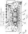
- Fig. 1 illustrates a first axial cross-sectional view of a spindle assembly 1 for a tire inflation system
- the term "axial” denotes that the cross-sectional view is taken along a cross-sectional plane which comprises a z-axis 2 of a cylindrical coordinate system, wherein the z-axis 2 is defined by a symmetry axis of a spindle 3.
- the arrow on the z-axis 2 defines a positive z-direction pointing to the right in Fig. 1 .
- a radial axis 4 of the cylindrical coordinate system is perpendicular to the z-axis 2.
- the stationary spindle 3 is part of a front axle of a tractor (not shown).
- a wheel hub 5 is made of steel or of another iron-based material and is rotatably mounted on the stationary spindle 3 by means of a pair of roller bearings comprising an external bearing 6a and an internal bearing 6b.
- the essentially cylindrically symmetric wheel hub 5 is arranged concentrically with respect to the z-axis 2 and can rotate about the z-axis 2.
- the bearings 6a and 6b are spaced with respect to each other along the z-axis 2, their mutual distance along the z-axis 2 defining an axial section 7 with a length of approximately 8 cm. Further details of the spindle assembly 1 related to the tire inflation system are illustrated in the following figures.
- Fig. 2 depicts a detail of a second axial cross-sectional view of the spindle assembly 1, the second axial cross-sectional view of Fig. 2 being tilted with respect to the first axial cross-sectional view of Fig. 1 by a given polar angle.
- Fig. 2 shows a fluid conduit 8a disposed internal to the spindle and extending in the z-direction.
- the first fluid conduit 8a ends in a port 9a which is arranged at an outer peripheral surface 10 of the spindle 3.
- the first fluid conduit 8a is configured to be in fluid communication with a tire inflation control unit which includes a high pressure air source (not shown).
- a diameter 11 of the first fluid conduit 8a is about 0.6 cm.
- the wheel hub 5 comprises a first fluid passage 12a which is disposed internal to the wheel hub 5.
- the first fluid passage 12a ends in a port 13a which is arranged at an inner peripheral surface 14 of the wheel hub 5, the ports 9a and 13a being situated at the same first axial position 15 along the z-axis 2.
- the first fluid passage 12a is configured to be in fluid communication with a pneumatic tire mounted on the front axle of the tractor.
- a metal bushing 16 is mounted on the spindle 3, the bushing 16 extending over the entire axial length of the axial section 7.
- An inner radius of the bushing has a length of approximately 10 cm and thus by about 0.5 mm larger than a radius of the spindle 3 on which the bushing 16 is mounted, resulting in a small radial clearance in between the inner peripheral surface 17 of the bushing and the outer peripheral surface 10 of the spindle 3 over an entire axial length of the bushing.
- 0-rings 18a, 18b and 18c are disposed radially between the spindle 3 and the bushing 16 and are partially received in corresponding annular recesses in the inner peripheral surface 17 of the bushing 16, the o-rings functioning as fluid seals.
- the bushing features a first annular indentation 20a and a second annular indentation 20b which are engraved in the inner peripheral surface 17 of the bushing, the indentations 20a and 20b thereby forming annular fluid channels between the bushing 16 and the spindle 3 (see Fig. 8 for an illustration of the annular fluid channel formed by the annular indentation 20b).
- Said annular fluid channels are fluidly sealed by the o-rings 18a, 18b and 18c.
- the first fluid conduit 8a is in fluid communication with the annular channel formed by the annular indentation 20a through the port 9a.
- fluid communication between the annular indentations 20a and 20b and an outer peripheral surface 21 of the bushing 16 is realized by means of radial through holes 32a and 32b which extend through the bushing 16 in the radial direction 4 and which are indicated by dashed lines in Fig. 2 .
- the radial through holes 32a and 32b are more clearly shown in Fig. 6 .
- the bushing 16 is fixed in between the bearings 6a and 6b. Relative rotational motion between the bushing 16 and the spindle 3 is blocked by a mechanical feature described in more detail further below (see Fig. 6 ).
- annular metal cartridges 22a and 22b are disposed radially between the wheel hub 5 and the bushing 16.
- the cartridges 22a and 22b can be made partially or entirely of a plastic material.
- the cartridges 22a and 22b are disposed radially between the wheel hub 5 and the spindle 3.
- the first cartridge 22a is fixedly mounted with its outer peripheral surface 23a on the inner peripheral surface 14 of the wheel hub 5.
- the second cartridge 22b is fixedly mounted with its outer peripheral surface 23b on the inner peripheral surface 14 of the wheel hub 5. Rotational motion of the cartridges 22a and 22b with respect to the wheel hub is thus prevented and the cartridges 22a and 22b are configured to co-rotate along with the wheel hub 5 about the z-axis 2.
- At least 20 percent of the outer peripheral surface 23a of the first metal cartridge 22a is in direct mechanical contact with and tightly fitted on the inner peripheral surface 14 of the metal wheel hub 5.
- at least 20 percent of the outer peripheral surface 23b of the second metal cartridge 22a is in direct mechanical contact with and tightly fitted on the inner peripheral surface 14 of the metal wheel hub 5.
- the tightly fitted metal to metal contact between the cartridges 22a and 22b and the wheel hub 5 additionally guarantees efficient heat conduction from the cartridges 22a and 22b to the wheel hub 5.
- the tight fit between the cartridges 22a and 22b and the wheel hub 5 is realized through corresponding shapes of the outer peripheral surfaces 23a and 23b of the cartridges 22a and 22b on one hand and of the inner peripheral surface 14 of the wheel hub 5 on the other, the corresponding shapes resulting in a tight form-fit between these components.
- an outer radius of the first cartridge 22a precisely fits an inner radius of the wheel hub 5.
- an outer radius of the second cartridge 22b precisely fits the inner radius of the wheel hub 5.
- the cartridges 22a and 22b can be brought into the afore-described tight fit with the wheel hub 5 by means of a mechanical press.
- the cartridges 22a and 22b are received radially inside the wheel hub 5 and are in tight mechanical engagement with the latter.
- the inner radius of the wheel hub 5 varies along the axial direction 2.
- the inner radius of the wheel hub 5 takes on different values, thereby forming a first shoulder 26a and a second shoulder 26b on the inner peripheral side 14 of the wheel hub 5.
- the first cartridge 22a is braced against the first shoulder 26a and the second cartridge 22b is braced against the second should 26b.
- the first cartridge 22a is fixed in between the first shoulder 26a and the second cartridge 22b and the second cartridge 22b is fixed in between the second shoulder 26b and an adapter 27, the adapter 27 itself being fixed in the axial direction 2 in between a third shoulder 26a on the inner peripheral side 14 of the wheel hub 5 and the external bearing 6a.
- the first cartridge 22a features at least one through hole 28a, the through hole 28a extending through the cartridge 22a in the radial direction 4.
- the through hole 28a of the first cartridge 22a extends from an inner peripheral end 29a of the first cartridge 22a to the outer peripheral surface 23a of the first cartridge 22a.
- the first cartridge 22a features a pair of annular sealing lips 30a which are mechanically clamped to the inner peripheral end 29a of the first cartridge 22a.
- the annular sealing lips 30a are made of a PTFE-based material.
- the first annular seal chamber 31a is thus disposed radially on the inside of the inner peripheral end 29a of the first cartridge.
- first annular seal chamber 31a is disposed radially on the outside of the outer peripheral surface 10 of the spindle 3 and radially on the outside of the outer peripheral surface 17 of the bushing 16.
- the sealing lips 30a are in sliding sealing contact with the bushing 16, making the first annular seal chamber 30a a dynamic annular seal chamber.
- the outer peripheral surface 23a of the first cartridge 22a features an annular indentation 33a which is enclosed on both sides axially by a pair of o-rings 34a, the o-rings 34a thereby enclosing and sealing the annular indentation 33a in the axial direction 2.
- the annular indentation 33a of the first cartridge 22a forms an annular fluid channel disposed radially between the inner peripheral surface 14 of the wheel hub 5 and the outer peripheral surface 23a of the first cartridge 22a.
- the through hole 28a fluidly connects the first annular seal chamber 30a with the annular indentation 33a of the first cartridge 22a. Fluid communication between the annular indentation 33a of the first cartridge 22a and the first fluid passage 12a internal to the wheel hub 5 is realized through the port 13a of the first fluid passage 12a, the fluid passage 12a ending in the annular indentation 33a of the first cartridge 22a at the port 13a.
- the first fluid conduit 8a internal to the spindle 3 is in fluid communication with the first fluid passage 12a internal to the wheel hub 5 through a first fluid passageway, the first fluid passageway comprising: the port 9a; the first annular indentation 20a of the bushing 16, the indentation 20a being axially sealed by the o-rings 18a and 18b; the through hole 32a in the bushing 16; the dynamic first annular seal chamber 30a; the through hole 28a through the first cartridge 22a; the annular indentation 33a of the first cartridge, the annular indentation 33a being axially sealed by the pair of o-rings 34a; and the port 13a.
- all of the fluid lines making up the first passageway are arranged at the same axial position 15 or at least in the same axial section 24a along the spindle axis 2.
- Fig. 3 shows a third axial cross-sectional view of the spindle assembly 1.
- the spindle 3 comprises a second fluid conduit 8b, the second fluid conduit 8b being disposed internal to the spindle 3 and being fluidly separated from the first fluid conduit 8a shown in Fig. 2 .
- the second fluid conduit 8b is configured to be in fluid communication with the tire pressure control unit briefly described above.
- the wheel hub 5 comprises a second fluid passage 12b, the second fluid passage 12b being disposed internal to the wheel hub 5 and being fluidly separated from the first fluid passage 12a shown in Fig. 2 .
- the second fluid passage 12b is used for piloting a retaining valve, wherein said retaining valve controls a fluid flow through the first fluid passage 12a which is used for inflating and deflating the pneumatic tire.
- the second fluid passage 12b is not used for piloting a retaining valve as shown here but is used like the first fluid passage 12a for directly inflating and/or deflating the pneumatic tire.
- the second fluid conduit 8b and the second fluid passage 12b are in fluid communication through a second fluid passageway, the second fluid passageway comprising: a port 9b at the outer peripheral surface 10 of the spindle 3; the second annular indentation 20b of the bushing 16, the indentation 20b being axially sealed by the o-rings 18b and 18c; a through hole 32b in the bushing 16; a dynamic second annular seal chamber 31b, said second annular seal chamber being formed by the outer peripheral surface 21 of the bushing, a pair of annular sealing lips 30b and an inner peripheral end 29b of the second cartridge 22b; a through hole 28b through the second cartridge 22b; an annular indentation 33b of the second cartridge 22b, the annular indentation 33b being axially sealed by a pair of o-rings 34b; and a port 13b at the inner peripheral surface 14 of the wheel hub 5. All of the fluid lines making up
- the spindle assembly 1 additionally shows an external rubber oil ring 35a and an internal rubber oil ring 35b, the oil rings 35a and 35b sealing the dynamic annular seal chambers 31a and 31b as well as the cartridges 22a and 22b from the bearings 6a and 6b. That is, the oil rings 35a and 35b seal the first and the second fluid passageway from the pair of bearings 6a and 6b, thereby preventing the mixing of fluid leaked out of the first or the second fluid passageway with lubricant used for lubricating the bearings 6a and 6b.
- the oil rings 35a and 35b are axially spaced with respect to each other and are axially disposed between the bearings 6a and 6b.
- the oil rings 6a and 6b are disposed radially between the wheel hub 5 and the spindle 3. More specifically, the internal oil ring 35b is mounted on the inner peripheral surface 14 of the wheel hub 5 and is in sliding sealing contact with the outer peripheral surface 21 of the bushing 16.
- the external oil ring 35a is mounted on the adapter 27. Like the oil ring 35b, the oil ring 35a is in sliding sealing contact with the outer peripheral surface 21 of the bushing 16.
- the oil rings 35a and 35b, the bushing 16, the adapter 27 and the wheel hub 5 form a sealed chamber 36.
- the sealed chamber 36 is disposed radially on the inside of the wheel hub 5 and is disposed radially on the outside of the spindle 3, more specifically on the outside of the bushing 16.
- the seal chamber 36 is enclosed and sealed by the wheel hub 5, the bushing 16, the adapter 27 and the oil rings 35a and 35b.
- the first cartridge 22a and the first annular seal chamber 31a on one hand, and the second cartridge 22b and the second annular seal chamber 31b on the other divide the sealed chamber 36 in three compartments 36a, 36b and 36c.
- the first compartment 36a is disposed axially between the external oil ring 35a and the second cartridge 22b
- the second compartment 36b is disposed axially between the second cartridge 22b and the internal first cartridge 22a
- the third compartment 36c is disposed axially between the first cartridge 22a and the internal oil ring 35b.
- Fig. 4 shows a fourth axial cross-sectional view of the spindle assembly 1.
- a breather line 38 is disposed internal to the wheel hub 5.
- the breather line 38 is in fluid communication with the compartment 36c through a port 39 which is arranged at the inner peripheral surface 14 of the wheel hub 5.
- a port 40 arranged at an external surface 41 of the wheel hub 5 the breather line 38 is configured to be in fluid communication with the external environment 37.
- a pressure relief valve 42 disposed at the port 40 is configured to exhaust the leaked out fluid to the external environment 37 if a fluid pressure in the breather line 38 exceeds a threshold value.
- a first fluid channel 43a of the first cartridge 22a which extends through the first cartridge 22a along the axial direction 2 fluidly connects the third compartment 36c with the second compartment 36b.
- the third compartment 36c is a volume which is disposed towards the negative z-direction with respect to the first passageway or with respect to the first dynamic annular seal chamber 31a or with respect to the first cartridge 22a.
- the second compartment 36b is a volume which is disposed towards the positive z-direction with respect to the first passageway or with respect to the first dynamic annular seal chamber 31a or with respect to the first cartridge 22a.
- the first fluid channel 43a bridges or leads across or leads around the first fluid passageway and the first annular seal chamber 31a.
- the second cartridge 22b comprises at least one fluid channel 44b (see Fig. 6 ) which extends through the second cartridge 22b along the axial direction, thereby fluidly connecting the first compartment 36a with the second compartment 36b.
- the first cartridge 22a features an annular indentation 45a.
- the second cartridge 22b features an annular indentation 45b.
- Said annular indentations 45a and 45b form an annular fluid channel disposed axially between the cartridges 22a and 22b, said channel forming part of the second compartment 36b.
- the axial fluid channel 43a and further axial fluid channels of the first cartridge 22a, such as the fluid channel 44a shown in Fig. 6 end in the annular fluid channel formed by the indentations 45a and 45b.
- the axial fluid channel 44b of the second cartridge 22b (see Fig. 6 ) and further axial fluid channels of the second cartridge 22b end in the annular fluid channel formed by the indentations 45a and 45b.
- the compartments 36a, 36b and 36c are in fluid communication with each other through the axial fluid channels in the cartridges 22a and 22b and through the annular fluid channel formed by the indentation 45a and 45b.
- FIG. 6 An illustration of the fluid connection between the compartments 36a, 36b and 36c with the breather line 38 through axial fluid channels 44a and 44b in the cartridge 22a and 22b is given in Fig. 6, Fig. 6 showing a detail of a fifth axial cross-sectional view of the spindle assembly 1.
- the afore described features related to the axial fluid channels of the cartridge 22a and 22b allow that fluid leaked out of the annular seal chambers 31a and 31b into any of the compartments 36a, 36b and 36c can be efficiently led away to the single breather line 38 and exhausted to the external environment 37.
- an unwanted build-up of high fluid pressure in the seal chamber 36 due to leaked out fluid is efficiently prevented.
- FIG. 7 A detail of radial cross-sectional view of the spindle assembly 1 corresponding to the axial position 19 (dashed line in Fig. 3 ) is shown in Fig. 7 .
- Fig. 7 shows the spindle 3 with the fluid conduits 8a and 8b, the fluid conduit 8b ending, at the port 9b at the outer peripheral surface 10 of the spindle 3, in the annular channel formed by the annular indentation 20b in the inner peripheral surface 17 of the bushing 16.
- the through hole 32b see Figs.
- Fig. 8 depicts a detail of a sixth axial cross-sectional view of the spindle assembly 1.
- Fig. 8 illustrates features that are not explicitly shown in the previous figures, such as the through holes 32a and 32b in the bushing 16 or the through hole 28b in the second cartridge 22b, the latter merely being shown as dashed lines in Fig. 2 .
- Fig. 8 illustrates features that are not explicitly shown in the previous figures, such as the through holes 32a and 32b in the bushing 16 or the through hole 28b in the second cartridge 22b, the latter merely being shown as dashed lines in Fig. 2 .
- Fig. 8 depicts a detail of a sixth axial cross-sectional view of the spindle assembly 1.
- Fig. 8 illustrates features that are not explicitly shown in the previous figures, such as the through holes 32a and 32b in the bushing 16 or the through hole 28b in the second cartridge 22b, the latter merely being shown as dashed lines in Fig. 2 .
- the sphere 47 is made of a metal material, e. g. steel or another iron-based material.
- the recesses 46a and 46b are configured as spot facings. In alternative embodiments they could be realized as bores, slots or any other type of recess.
- a modified embodiment can provide that the sphere 47 is replaced by a metal gudgeon, a Woodruff key, a feather key, preferably all made of a metal material such as steel or iron.
- the sphere 47 is tightly enclosed by the material of the bushing 16 surrounding the first recess 46a.
- the sphere and the recess 46a are in a tight and precisely machined form-fit, there being no or only minimal clearance between the bushing 16 and the sphere 47 at least in the angular direction.
- a depth of the first recess 46a in which the sphere 47 is received has a length 48 that is preferably 70 percent of a diameter 49 of the sphere 47.
- an axial length 50 of the recess 46a is about twice the diameter 49 of the sphere 47.
- both the sphere 47 and the bushing 16 are held in place by a mount 51 of the external bearing 6a.
- the second recess 46b has a shape which is precisely machined to be in a form-fit with a portion of the sphere 47 protruding from the first recess 46a in the radial direction 4. That is, the sphere 47 and the second recess 46b are in a tight form-fit along the angular direction. Accordingly, a rotational motion of the bushing 16 with respect to the spindle 3 that could be effected, for example, by friction between the pairs of sealing lips 30a and 30b clamped to the cartridges 22a and 22b and the bushing 16 is efficiently blocked.
- Fig. 9 shows a detail of a axial cross-sectional view of a second embodiment of a spindle assembly 1' for a tire inflation system.
- the embodiment shown in Fig. 9 features no bushing mounted on the spindle 3.
- the dynamic annular seal chambers 31a and 31b are realized by means of annular metal collars 52a and 52b, respectively, which are mounted on the outer peripheral surface 10 of the spindle 3.
- the annular seal chambers 31a and 31b are formed and enclosed by annular plastic components 53a and 53b, respectively, which are attached to the inner peripheral surface 29a of the single cartridge 22a.
- the single cartridge 22a comprises both radial through holes 28a and 28b which in the previously described embodiment were included in the two separate cartridges 22a and 22b.
- annular seal chambers 31a and 31b are formed by means of two pairs of flexible annular wedge rings, namely a first pair 54a and a second pair 54b, which are arranged radially between the plastic components 53a and 53b and the metal collars 52a and 52b, respectively.
- the oil seals 35a and 35b are directly mounted on the inner peripheral surface 29a of the cartridge 22a.
- annular seal chamber 31b formed by the annular metal collar 52b, the annular plastic component 53b and the pair of wedge rings 54b is now described with reference to Fig. 10 which shows a detail of Fig. 9 .
- An axial cross-sections of both the metal collar 52b and the annular plastic component 53b feature approximately U-like shapes, the round side of the U pointing towards the spindle axis 2, respectively.
- An axial length 55b of an inner axial diameter of the metal collar 52b is slightly larger than an axial length 56b of an outer axial diameter of the plastic component 53b attached to the cartridge 22a, the plastic component 53b thereby being at least partially received in the collar 52b.
- the length 55b can be larger than the length 56b by between 0.5 and 5 percent of the length 55b or by between 1 and 3 percent of the length 55b.
- an inner peripheral end 57b of the plastic component 53b is not in contact with an outer peripheral surface 59b of a central portion 58b of the collar 52b.
- the plastic component 53b is not in contact and/or not in sliding sealing contact with the metal collar 52b in which the plastic component 53b is at least partially received in the radial direction.
- the metal collar 52b features one or several radial through holes, for example the through hole 67b shown in Fig. 10 .
- the plastic component 53b features one or several radial through holes at its inner peripheral end 57b, for example the radial through hole 68b shown in Fig. 10 . Further through holes of the plastic component 53b may be disposed at different angular locations of the inner peripheral end 57b of the plastic component 53b.
- the sealing of the dynamic annular seal chamber 31b is effected by the pair of wedge rings 54b.
- An axial cross-sectional area of the wedge rings 54b has a wedge-like shape, the sharp end 60b of the wedge rings 54b pointing towards a central axis 61b of the metal collar 52b.
- An inner surface 62b of the wedge rings 54b, that is a surface of the wedge rings 54b facing the central axis 61b has a shape which is complementary to a shape of an outer surface 63b of a tapering portion 64b of the plastic component 53b.
- the wedge rings 54b are disposed axially in such as to abut on the axially outward lying upright sections 65b of the collar 52b.
- An axial length 66b of the rings 54b is about 25 percent of the axial length 55b of the inner axial diameter of the metal collar 52b. In slightly varied embodiments the axial length 66b can be between 10 percent and 40 percent, more typically between 15 percent and 30 percent of the axial length 55b of the inner axial diameter of the collar 52b.
- Fig. 10 shows the annular seal chamber 31b in a pressurized state.
- the annular wedge rings 54b are pressed in the positive radial direction such that they abut on and are pressed against the outer surface of the tapering portion 64b of the plastic component 53b, and such that they abut on and are pressed against an inner surface 69b of the upright sections 65b of the metal collar 52b, thereby sealing the annular seal chamber 31b.
- a non-pressurized state (not shown) the annular wedge rings 54b abut on the outer peripheral surface 59b of the central portion 58b of the metal collar 52b, that is in the non-pressurized state the wedge rings 54b clasp around the metal collar 52b.
- the radial movement of the wedge rings 54b between the pressurized and the non-pressurized state can be facilitated by a radial cut in the wedge rings 54b, the cut allowing a length of a radius of the wedge rings 54b to vary between a first length in the pressurized state, and a second length in the non-pressurized state, the first length being larger than the second length, for example by between 1 percent and 5 percent of the first length.
- Fig. 11 schematically shows a detail of an axial cross-sectional view of a further embodiment of a spindle assembly 100 comprising the spindle 3 and the wheel hub 5 which can rotate about the axis 2 defined by the spindle 3.
- a fluid passage 12c is arranged internal to the spindle 3 and a fluid conduit 8c is arranged internal to the wheel hub 5.
- the fluid conduit 8c is in fluid connection with a pneumatic tire and the fluid passage 12c is in fluid connection with a pressure control unit (not shown).
- the fluid conduit 8c and the fluid passage 12c are furthermore in fluid communication with each other through an annular seal chamber 31c.
- the annular seal chamber 31c is formed by a pair of rubber sealing lips 30c which are mounted on the inner peripheral surface 14 of the wheel hub 5 and which are in sliding sealing contact with the outer peripheral surface 10 of the spindle 3.
- the annular seal chamber 13c is arranged in between a first volume 70a and a second volume 70b along the axial direction 2, thereby separating the first volume 70a from the second volume 70b.
- a fluid channel 43c is arranged internal to the wheel hub 5 and fluidly connects the first volume 70a with the second volume 70b.
- fluid leaked out into the volumes 70a and/or 70b from the annular seal chamber 31c can be led through the fluid channel 43c:
- another fluid channel 43d is arranged internal to the spindle 3 and fluidly connects the first volume 70a with the second volume 70b.
- fluid leaked out into the volumes 70a and/or 70b from the annular seal chamber 31c can be led through the fluid channel 43d.
- the fluid channels 43c and 43d are fluidly separated from the fluid conduit 8c, the annular seal chamber 31c and the fluid passage 12c. In Fig. 11 this is indicated by fact that the fluid conduit 8c and the fluid passage 12c are drawn in dashed lines.
- a breather line which is arranged internal to the wheel hub 5 and which connects the first volume 70a with the external environment.
Landscapes
- Engineering & Computer Science (AREA)
- Mechanical Engineering (AREA)
- Sealing Devices (AREA)
Claims (16)
- Achsenanordnung (1; 100) für ein Reifenfüllsystem, welche Achsenanordnung (1) aufweist:einen Achszapfen (3), der eine axiale Richtung (2) definiert und eine Fluidleitung (8a, 8b; 8c) aufweist;ein drehbares Teil (5), das drehbar auf dem Achszapfen (3) angebracht ist und einen Fluiddurchgang (12a, 12b; 12c) aufweist, wobei der Fluiddurchgang (12a, 12b; 12c) konfiguriert ist, in Fluidverbindung mit einem pneumatischen Reifen zu sein; undeine dynamische ringförmige Abdichtkammer (31a, 31b; 31c), wobei die ringförmige Abdichtkammer (31a, 31b; 31c) radial zwischen dem Achszapfen (3) und dem drehbaren Teil (5) angeordnet ist;wobei die Fluidleitung (8a, 8b; 8c) und der Fluiddurchgang (12a, 12b; 12c) durch die ringförmige Abdichtkammer (31a, 31b; 31c) in Fluidverbindung miteinander sind und die ringförmige Abdichtkammer (31a, 31b; 31c) sich axial zwischen einem ersten Hohlraum und einem zweiten Hohlraum befindet;wobei der erste Hohlraum und der zweite Hohlraum durch einen Fluidkanal (43a, 43b, 44a, 44b; 43c, 43d) miteinander in Fluidverbindung sind zum Leiten von Fluid, das aus der ringförmigen Abdichtkammer (31a, 31b; 31c) entwichen ist und in den ersten Hohlraum und/oder in den zweiten Hohlraum entwichen ist, durch den Fluidkanal (43a, 43b, 44a, 44b; 43c, 43d), wobei ein erstes Ende des Fluidkanals in dem ersten Hohlraum endet, ein zweites Ende des Fluidkanals in dem zweiten Hohlraum endet und wobei der Fluidkanal um die ringförmige Abdichtkammer (31a, 31b; 31c) herum leitet.
- Achsenanordnung (1) nach Anspruch 1, gekennzeichnet durch ein drehbares Element (22a, 22b), das an einer inneren Umfangsseite (14) des drehbaren Teils (5) angebracht ist, wobei die ringförmige Abdichtkammer (31a, 31b) radial innerhalb eines inneren Umfangsendes (29a, 29b) des drehbaren Elements (22a, 22b) zwischen dem drehbaren Element (22a, 22b) und dem Achszapfen (3) angeordnet ist, wobei das drehbare Element (22a, 22b) zumindest ein Durchgangsloch (28a, 28b, 28c, 28d, 28e) zum fluidmäßigen Verbinden des Fluiddurchgangs (12a, 12b) mit der ringförmigen Abdichtkammer (31a, 31b) aufweist und wobei der Fluidkanal (43a, 43b, 44a, 44b) vorzugsweise als eine Öffnung oder als eine Durchgangsbohrung in dem drehbaren Element (22a, 22b) konfiguriert ist.
- Achsenanordnung (1) nach Anspruch 2, dadurch gekennzeichnet, dass der Achszapfen (3) zumindest eine zweite Fluidleitung (8b) aufweist;das drehbare Teil (5) zumindest einen zweiten Fluiddurchgang (12b) aufweist;zumindest ein zweites drehbares Element (22a, 2b) an der inneren Umfangsseite (14) des drehbaren Teils (5) angebracht ist, eine zweite ringförmige Abdichtkammer (31b) radial innerhalb eines inneren Umfangsendes (29b) des zweiten drehbaren Elements (22a, 22b) zwischen dem zweiten drehbaren Element (22a, 22b) und dem Achszapfen (3) angeordnet ist, wobei das zweite drehbare Element (22a, 22b) zumindest ein zweites Durchgangsloch (28b, 28c, 28d, 28e) zum fluidmäßigen Verbinden des zweiten Fluiddurchgangs (12b) mit der zweiten ringförmigen Abdichtkammer (31b) aufweist;wobei die zweite Fluidleitung (8b) und der zweite Fluiddurchgang (12b) durch die zweite ringförmige Abdichtkammer (31b) in Fluidverbindung miteinander sind und die zweite ringförmige Abdichtkammer (31b) axial zwischen dem zweiten Hohlraum und einem dritten Hohlraum angeordnet ist; undwobei der zweite Hohlraum und der dritte Hohlraum in Fluidverbindung miteinander sind durch zumindest einen zweiten Fluidkanal (43b, 44b) zum Leiten von Fluid, das aus der zweiten ringförmigen Abdichtkammer (31b) entwichen ist und in den zweiten Hohlraum und/oder in den dritten Hohlraum durch den zweiten Fluidkanal (43b, 44b) entwichen ist, wobei der zweite Fluidkanal (43b, 44b) als eine Öffnung oder als eine Durchgangsbohrung in dem zweiten drehbaren Element (22a, 22b) konfiguriert ist.
- Achsenanordnung (1) nach einem der vorhergehenden Ansprüche, gekennzeichnet durch eine Entlüftungsleitung (38), die auf dem drehbaren Teil oder innerhalb des drehbaren Teils (5) angeordnet ist, wobei die Entlüftungsleitung (38) in Fluidverbindung mit dem ersten Hohlraum und mit dem zweiten Hohlraum ist und die Entlüftungsleitung (38) konfiguriert ist zum Leiten von Fluid, das aus der ringförmigen Abdichtkammer (31a, 31b) zu einer externen Umgebung (37) hin entwichen ist.
- Achsenanordnung (1) nach einem der Ansprüche 2-4, dadurch gekennzeichnet, dass das drehbare Element (22a, 22b) fest an dem drehbaren Teil (5) derart angebracht ist, dass eine relative radiale Bewegung und eine relative Drehbewegung des drehbaren Elements (22a, 22b) mit Bezug auf das drehbare Teil (5) blockiert sind.
- Achsenanordnung (1) nach Anspruch 5, dadurch gekennzeichnet, dass zumindest 5 Prozent, zumindest 10 Prozent, zumindest 15 Prozent oder zumindest 20 Prozent einer äußeren Umfangsfläche des drehbaren Elements (22a, 22b) in direktem mechanischem Kontakt mit der und eng auf die innere Umfangsfläche des drehbaren Teils (5) aufgesetzt sind, um Wärme von dem drehbaren Element (22a, 22b) zu dem drehbaren Teil (5) zu leiten.
- Achsenanordnung (1) nach einem der vorhergehenden Ansprüche, dadurch gekennzeichnet, dass die ringförmige Abdichtkammer (31a, 31b) durch Abdichtmittel, die eine auf dem Achszapfen (3) angebrachte Buchse (16) aufweisen, gebildet ist, wobei ein radialer Abstand zwischen dem Achszapfen (3) und der Buchse (16) entlang einer axialen Verlängerung der Buchse (16) besteht.
- Achsenanordnung (1) nach Anspruch 7, gekennzeichnet durch entsprechende mechanische Merkmale, die auf einer äußeren Umfangsfläche des Achszapfens (3) und auf einer inneren Umfangsfläche der Buchse (16) angebracht sind, wobei die entsprechenden mechanischem Merkmale in einem gegenseitigen mechanischen Eingriff sind, wodurch eine relative Drehbewegung der Buchse (16) mit Bezug auf den Achszapfen (3) blockiert wird.
- Achsenanordnung (1) nach Anspruch 8, dadurch gekennzeichnet, dass die entsprechenden mechanischen Merkmale eine erste Vertiefung (46a) in der äußeren Umfangsfläche des Achszapfens (3), eine zweite Vertiefung (46b) in der inneren Umfangsfläche der Buchse (16) und einen mechanischen Keil aufweisen, wobei der mechanische Keil konfiguriert ist, vollständig oder zumindest teilweise in der ersten Vertiefung (46a) und gleichzeitig vollständig oder zumindest teilweise in der zweiten Vertiefung (46b) aufgenommen zu werden.
- Achsenanordnung (1) nach Anspruch 9, dadurch gekennzeichnet, dass die erste Vertiefung (46a) und/oder die zweite Vertiefung (46b) als eine Nabenfläche, eine Bohrung oder ein Schlitz konfiguriert sind und der mechanische Keil als eine Metallkugel (47), ein Metallzapfen, ein Woodruff-Keil oder ein Nutenkeil konfiguriert ist.
- Achsenanordnung (1) nach einem der Ansprüche 7 bis 10, dadurch gekennzeichnet, dass die Abdichtmittel weiterhin ein Paar von ringförmigen Abdichtlippen (30a, 30b) aufweisen, die an einem inneren Umfangsende (29a, 29b) des drehbaren Elements (22a, 22b) angebracht sind, wobei die ringförmigen Abdichtlippen (30a, 30b) in gleitendem abdichtendem Kontakt mit einer äußeren Umfangsfläche (21) der Buchse (16) sind.
- Achsenanordnung (1) nach einem der Ansprüche 1 bis 6, dadurch gekennzeichnet, dass die ringförmige Abdichtkammer (31a, 31b) durch Abdichtmittel gebildet ist, welche aufweisen:- einen ringförmigen Kragen (52a, 52b), der an einer äußeren Umfangsfläche (10) des Achszapfens (3) angebracht ist,- eine ringförmige Kunststoffkomponente (53a, 53b), die an einer inneren Umfangsfläche des drehbaren Elements (22a, 22b) angebracht und in dem Kragen (52a, 52b) aufgenommen ist,- und einen flexiblen Abdichtring (54a, 54b), der zwischen dem Kragen (52a, 52b) und der Kunststoffkomponente (53a, 53b) angeordnet ist.
- Achsenanordnung (1) nach einem der Ansprüche 2 bis 12, dadurch gekennzeichnet, dass das drehbare Teil (5) durch ein Paar von Lagern (6a, 6b) an dem Achszapfen (3) angebracht ist, wobei die Lager (6a, 6b) einen axialen Abstand zueinander aufweisen und wobei das drehbare Element (22a, 22b) und die Abdichtmittel axial zwischen den Lagern (6a, 6b) angeordnet sind.
- Achsenanordnung (1) nach Anspruch 13, gekennzeichnet durch ein Paar von ringförmigen Öldichtungen (35a, 35b), wobei die Öldichtungen (35a, 35b) die ringförmige Abdichtkammer (31a, 31b) gegenüber den Lagern (6a, 6b) abdichten.
- Achsenanordnung (1; 100) nach einem der vorhergehenden Ansprüche, dadurch gekennzeichnet, dass die Fluidleitung (8a, 8b; 8c) vollständig oder zumindest teilweise innerhalb des Achszapfens (3) angeordnet ist und/oder der Fluiddurchgang (12a, 12b; 12c) vollständig oder zumindest teilweise innerhalb des drehbaren Teils angeordnet ist.
- Achsenanordnung (1; 100) nach einem der vorhergehenden Ansprüche, dadurch gekennzeichnet, dass der Fluidkanal (43a, 43b, 44a, 44b; 43c, 43d) innerhalb des Achszapfens (3) oder innerhalb des drehbaren Teils (5) angeordnet ist.
Priority Applications (6)
| Application Number | Priority Date | Filing Date | Title |
|---|---|---|---|
| EP12164828.1A EP2653323B1 (de) | 2012-04-19 | 2012-04-19 | Achsanordnung für Reifenfüllsystem |
| RU2014146380/11A RU2570853C1 (ru) | 2012-04-19 | 2013-04-15 | Шпиндельный узел для системы накачивания шины |
| CN201380020919.0A CN104245367B (zh) | 2012-04-19 | 2013-04-15 | 用于轮胎充气系统的心轴组件 |
| PCT/EP2013/057781 WO2013156430A1 (en) | 2012-04-19 | 2013-04-15 | Spindle assembly for a tire inflation system |
| EP13717026.2A EP2838740A1 (de) | 2012-04-19 | 2013-04-15 | Spindelanordnung für reifenfüllsystem |
| US13/261,973 US9409449B2 (en) | 2012-04-19 | 2013-04-15 | Spindle assembly for a tire inflation system |
Applications Claiming Priority (1)
| Application Number | Priority Date | Filing Date | Title |
|---|---|---|---|
| EP12164828.1A EP2653323B1 (de) | 2012-04-19 | 2012-04-19 | Achsanordnung für Reifenfüllsystem |
Publications (2)
| Publication Number | Publication Date |
|---|---|
| EP2653323A1 EP2653323A1 (de) | 2013-10-23 |
| EP2653323B1 true EP2653323B1 (de) | 2016-03-23 |
Family
ID=45999691
Family Applications (2)
| Application Number | Title | Priority Date | Filing Date |
|---|---|---|---|
| EP12164828.1A Not-in-force EP2653323B1 (de) | 2012-04-19 | 2012-04-19 | Achsanordnung für Reifenfüllsystem |
| EP13717026.2A Withdrawn EP2838740A1 (de) | 2012-04-19 | 2013-04-15 | Spindelanordnung für reifenfüllsystem |
Family Applications After (1)
| Application Number | Title | Priority Date | Filing Date |
|---|---|---|---|
| EP13717026.2A Withdrawn EP2838740A1 (de) | 2012-04-19 | 2013-04-15 | Spindelanordnung für reifenfüllsystem |
Country Status (5)
| Country | Link |
|---|---|
| US (1) | US9409449B2 (de) |
| EP (2) | EP2653323B1 (de) |
| CN (1) | CN104245367B (de) |
| RU (1) | RU2570853C1 (de) |
| WO (1) | WO2013156430A1 (de) |
Families Citing this family (26)
| Publication number | Priority date | Publication date | Assignee | Title |
|---|---|---|---|---|
| EP2653323B1 (de) * | 2012-04-19 | 2016-03-23 | DANA ITALIA S.p.A | Achsanordnung für Reifenfüllsystem |
| EP2888119B1 (de) | 2012-08-20 | 2019-04-17 | Ice Adaptive Tires, LLC | Eisadaptives reifensystem |
| DE102013205399A1 (de) * | 2013-03-27 | 2014-10-02 | Robert Bosch Gmbh | Radnabenantrieb mit einem Planetengetriebe |
| DE102014210598A1 (de) | 2014-06-04 | 2015-12-17 | Zf Friedrichshafen Ag | Antreibbarer lenkbarer Radkopf |
| DE102014108028B3 (de) * | 2014-06-06 | 2015-09-24 | Kessler & Co. Gmbh & Co. Kg | Drehdurchführung für ein Kraftfahrzeugrad |
| WO2015195028A1 (en) * | 2014-06-18 | 2015-12-23 | Trelleborg Forsheda Ab | Sealing arrangement |
| RU2695714C2 (ru) * | 2014-07-02 | 2019-07-25 | Дана Италия Спа | Уплотнение вращательного соединения для системы централизированной накачки шин |
| DE102014213090A1 (de) | 2014-07-07 | 2016-01-07 | Zf Friedrichshafen Ag | Radkopf |
| US10266017B2 (en) | 2015-02-19 | 2019-04-23 | Dana Italia S.R.L. | Integration of sensor network and method of operation into a CTIS framework |
| EP3640062A1 (de) | 2015-12-29 | 2020-04-22 | Bridgestone Americas Tire Operations, LLC | Reifenschnellfüllverfahren |
| US11021023B2 (en) | 2015-12-29 | 2021-06-01 | Bridgestone Americas Tire Operations, Llc | Rapid tire inflation system with air compressor |
| US10953707B2 (en) | 2015-12-29 | 2021-03-23 | Bridgestone Americas Tire Operations, Llc | Air distribution system for rapid tire inflation |
| EP3208118A1 (de) | 2016-02-19 | 2017-08-23 | DANA ITALIA S.r.l. | Drehdurchführungsanordnung für eine reifenaufpumpanlage |
| EP3318427A1 (de) | 2016-11-04 | 2018-05-09 | DANA ITALIA S.r.l. | Drehkupplungsanordnung für ein reifenfüllsystem |
| WO2018136513A1 (en) * | 2017-01-17 | 2018-07-26 | Dana Automotive Systems Group, Llc | Ported wheel hub assembly and the tire inflation system made therewith |
| US10807413B2 (en) * | 2017-02-02 | 2020-10-20 | Dana Heavy Vehicle Systems Group, Llc | Front axle wheel assembly and the tire inflation system made therewith |
| FR3068300B1 (fr) * | 2017-06-30 | 2019-08-16 | Poclain Hydraulics Industrie | Appareil hydraulique ameliore comprenant une conduite pour la circulation d'air |
| IT201700085893A1 (it) * | 2017-07-27 | 2019-01-27 | Trelleborg Wheel Sys Italia Spa | Collettore rotante e sistema di regolazione della pressione di pneumatici. |
| WO2021212119A1 (en) * | 2020-04-17 | 2021-10-21 | Irh Inc. | A modular integrated tire inflation hub system and device |
| US11602952B2 (en) * | 2020-08-12 | 2023-03-14 | Arvinmeritor Technology, Llc | Wheel end assembly having a vent passage |
| US12583266B2 (en) * | 2022-05-09 | 2026-03-24 | Deere & Company | Tire inflation system |
| US12528318B2 (en) | 2022-05-27 | 2026-01-20 | Deere & Company | Compact rotary union assembly for a wheel hub |
| WO2024039840A2 (en) * | 2022-08-19 | 2024-02-22 | Consolidated Metco, Inc. | Wheel hub with passageway |
| DE202022107180U1 (de) | 2022-12-22 | 2024-03-27 | Dana Italia S.R.L. | Drehdurchführungsbaugruppe für ein Reifenfüllsystem |
| DE102023206415A1 (de) | 2023-07-06 | 2025-01-09 | Robert Bosch Gesellschaft mit beschränkter Haftung | Getriebeeinheit eines Fahrzeugs mit Drehdurchführungseinheit |
| DE102023206643A1 (de) * | 2023-07-13 | 2025-01-16 | Zf Friedrichshafen Ag | Reifendruckregelvorrichtung, landwirtschaftliches Nutzfahrzeug und Baumaschine |
Family Cites Families (39)
| Publication number | Priority date | Publication date | Assignee | Title |
|---|---|---|---|---|
| US5236028A (en) * | 1985-07-08 | 1993-08-17 | Am General Corporation | Vehicle wheel end assembly |
| US4730656A (en) * | 1985-07-08 | 1988-03-15 | Am General Corporation | Vehicle wheel end assembly |
| US5221381A (en) | 1989-06-28 | 1993-06-22 | General Motors Corporation | Vehicle tire pressure management system with easily removed wheel and tire |
| US4987937A (en) | 1989-07-03 | 1991-01-29 | Eaton Corporation | In-tire filter assembly for central tire inflation system |
| US5203391A (en) * | 1991-03-15 | 1993-04-20 | The Timken Company | Wheel mounting for tire pressure adjustment system |
| US5174839A (en) * | 1991-07-05 | 1992-12-29 | Eaton Corporation | Drive axle sleeve and seal assembly |
| EP0588595A1 (de) | 1992-09-15 | 1994-03-23 | Oshkosh Truck Corporation | Zentral-Reifendruckfülleinrichtung für originalen oder nachträglichen Einbau |
| SE503639C2 (sv) * | 1995-02-08 | 1996-07-22 | Ulf Rothman | Anordning för att manövrera en ventil |
| US5868881A (en) * | 1996-09-04 | 1999-02-09 | Equalaire Systems, Inc. | Rotary air coupling for tire inflation system |
| AT2364U1 (de) * | 1997-09-09 | 1998-09-25 | Steyr Daimler Puch Ag | Radträger für kraftfahrzeug mit reifenfüllanlage |
| US20050133134A1 (en) | 2001-11-13 | 2005-06-23 | Airgo Ip, Llc | Rotary union assembly for use in air pressure inflation systems for tractor trailer tires |
| AT3682U1 (de) * | 1999-01-13 | 2000-06-26 | Steyr Daimler Puch Ag | Anordnung mit konzentrisch zueinander angeordneten und relativ zueinander rotierbaren bauteilen und verwendung dieser anordnung bei einer reifenfüllanlage |
| US6363985B1 (en) * | 2000-04-18 | 2002-04-02 | Spice Technology, Inc. | Rotary air coupling for tire inflation system |
| US6182727B1 (en) * | 1999-06-30 | 2001-02-06 | Dana Corporation | Rotary air coupling for tire inflation system |
| DE19950191C1 (de) * | 1999-10-19 | 2001-05-10 | Tigges & Winckel Bonumwerke | Reifendruckregelanlage |
| US6283186B1 (en) * | 1999-11-23 | 2001-09-04 | Dana Corporation | Tire inflation system for live spindle wheel end |
| DE60206430T2 (de) * | 2001-02-22 | 2006-06-29 | ArvinMeritor Technology, LLC, Troy | Fahrzeugrad mit Endanordnung |
| DE10208024B4 (de) * | 2002-02-26 | 2005-06-02 | Gkn Walterscheid Gmbh | Drehdurchführung für eine Vorrichtung zum Füllen oder Entlüften eines Reifens eines Traktorrades |
| FR2836656B1 (fr) * | 2002-03-01 | 2004-05-28 | Michelin Soc Tech | Dispositif et procede de traitement des phenomenes de perte de pression et de roulage a plat des pneumatiques d'un vehicule |
| US6668888B1 (en) * | 2002-07-19 | 2003-12-30 | Torque-Traction Technologies, Inc. | Central tire inflation system for steering drive axle |
| US6892778B2 (en) * | 2003-09-09 | 2005-05-17 | Mark K. Hennig | Wheel end assembly high-temperature warning system |
| US20050161137A1 (en) | 2004-01-28 | 2005-07-28 | Hoang Quyen C. | Method for air pressure regulation and improved aesthetics in automobile wheels |
| FR2871537B1 (fr) * | 2004-06-15 | 2006-09-22 | Snr Roulements Sa | Palier a passage d'air dans un alesage pourvu de cannelures |
| JP4529899B2 (ja) * | 2005-12-28 | 2010-08-25 | トヨタ自動車株式会社 | 空気供給装置 |
| DE102006006143A1 (de) * | 2006-02-10 | 2007-08-23 | Schaeffler Kg | Dichtungsanordnung für eine Reifendruck-Reguliereinrichtung |
| US7896045B2 (en) * | 2006-11-13 | 2011-03-01 | The Board Of Regents For Oklahoma State University | Apparatus for delivering air through powered axle assemblies |
| DE102007058036A1 (de) * | 2007-02-06 | 2008-08-28 | Fereshteh Saadat | Fahrzeugfelge mit zentralem Ventil |
| DE102007005765A1 (de) * | 2007-02-06 | 2008-08-14 | Fereshteh Saadat | Radachse und Antriebs- oder Gelenkwelle |
| US20090084481A1 (en) * | 2007-10-01 | 2009-04-02 | Kalavitz Michael V | Tire inflation control method and apparatus |
| US7690412B1 (en) * | 2008-11-04 | 2010-04-06 | Arvinmeritor Technology, Llc | Drive axle with air passage for tire inflation system |
| EP2653323B1 (de) * | 2012-04-19 | 2016-03-23 | DANA ITALIA S.p.A | Achsanordnung für Reifenfüllsystem |
| US9604509B2 (en) * | 2012-10-26 | 2017-03-28 | Gv Engineering Gmbh | Vehicle axle assembly comprising integrated pressure medium line for filling tires |
| MX2015012956A (es) * | 2013-03-15 | 2015-12-01 | Dana Heavy Vehicle Sys Group | Ensamble. |
| US9315077B2 (en) * | 2013-09-04 | 2016-04-19 | Arvinmeritor Technology, Llc | Tire inflation system having a passage for routing pressurized gas through a hub |
| US9162539B2 (en) * | 2014-01-24 | 2015-10-20 | American Axle & Manufacturing, Inc. | Axle assembly having wheel hubs configured for use in vehicle with central tire inflation system |
| DE102014108028B3 (de) * | 2014-06-06 | 2015-09-24 | Kessler & Co. Gmbh & Co. Kg | Drehdurchführung für ein Kraftfahrzeugrad |
| US9481213B2 (en) * | 2014-06-24 | 2016-11-01 | Arvinmeritor Technology, Llc | Tire inflation system having a seal |
| US9511635B2 (en) * | 2014-07-10 | 2016-12-06 | Airgo Ip, Llc | Apparatus for delivering air through powered axle assemblies |
| US9352621B2 (en) * | 2014-07-15 | 2016-05-31 | Arvinmeritor Technology, Llc | Tire inflation system having a pressure relief valve |
-
2012
- 2012-04-19 EP EP12164828.1A patent/EP2653323B1/de not_active Not-in-force
-
2013
- 2013-04-15 RU RU2014146380/11A patent/RU2570853C1/ru not_active IP Right Cessation
- 2013-04-15 CN CN201380020919.0A patent/CN104245367B/zh not_active Expired - Fee Related
- 2013-04-15 EP EP13717026.2A patent/EP2838740A1/de not_active Withdrawn
- 2013-04-15 WO PCT/EP2013/057781 patent/WO2013156430A1/en not_active Ceased
- 2013-04-15 US US13/261,973 patent/US9409449B2/en active Active
Also Published As
| Publication number | Publication date |
|---|---|
| EP2838740A1 (de) | 2015-02-25 |
| CN104245367B (zh) | 2017-10-31 |
| US9409449B2 (en) | 2016-08-09 |
| CN104245367A (zh) | 2014-12-24 |
| US20150068653A1 (en) | 2015-03-12 |
| WO2013156430A1 (en) | 2013-10-24 |
| EP2653323A1 (de) | 2013-10-23 |
| RU2570853C1 (ru) | 2015-12-10 |
Similar Documents
| Publication | Publication Date | Title |
|---|---|---|
| EP2653323B1 (de) | Achsanordnung für Reifenfüllsystem | |
| EP3164273B1 (de) | Drehdichtung für eine zentrale reifenaufpumpanlage | |
| US6145558A (en) | Seal arrangement for a central tire inflation system | |
| US20090084481A1 (en) | Tire inflation control method and apparatus | |
| EP3439895B1 (de) | Verbindungsvorrichtung einer fahrzeugachse | |
| CA2465980A1 (en) | Erosion resistant drilling head assembly | |
| EP0362921B1 (de) | Ein an einen Wälzlager angeordneter Dichtungsring zur Verbindung von zwei Fluidbehältern mit unterschiedlichem Druck, wobei wenigstens einer bezüglich des anderen drehbar ist | |
| US20160368329A1 (en) | Pneumatic system for inflating a wheel, integrated to a driven axle | |
| US11298988B2 (en) | Rotary joint assembly for a tire inflation system | |
| CN106715162B (zh) | 用于对车辆车轮供应压缩空气的组件 | |
| JP2022532101A (ja) | シャフトの内部にある流体管に制御圧力及び/又は作動圧力を伝達する回転型伝達装置 | |
| EP3075574B1 (de) | Aktuator | |
| EP3416834B1 (de) | Drehdurchführungsanordnung für eine reifenaufpumpanlage | |
| WO2011090787A1 (en) | Drive axle seal body and tire inflation system | |
| EP3985272B1 (de) | Radnabe für ein landwirtschafts- oder arbeitsfahrzeug | |
| US11077726B2 (en) | Front axle rotary joint assembly and the tire inflation system made therewith | |
| US20250180145A1 (en) | Rotary joint assembly for providing a tire inflation system | |
| EP4565436A1 (de) | Drehdurchführungsanordnung | |
| EP3169537A1 (de) | Drehverbindungsanordnung für ein reifendruckverwaltungssystem | |
| JP2008230576A (ja) | 車両用空気供給機構 |
Legal Events
| Date | Code | Title | Description |
|---|---|---|---|
| PUAI | Public reference made under article 153(3) epc to a published international application that has entered the european phase |
Free format text: ORIGINAL CODE: 0009012 |
|
| AK | Designated contracting states |
Kind code of ref document: A1 Designated state(s): AL AT BE BG CH CY CZ DE DK EE ES FI FR GB GR HR HU IE IS IT LI LT LU LV MC MK MT NL NO PL PT RO RS SE SI SK SM TR |
|
| AX | Request for extension of the european patent |
Extension state: BA ME |
|
| 17P | Request for examination filed |
Effective date: 20140423 |
|
| RBV | Designated contracting states (corrected) |
Designated state(s): AL AT BE BG CH CY CZ DE DK EE ES FI FR GB GR HR HU IE IS IT LI LT LU LV MC MK MT NL NO PL PT RO RS SE SI SK SM TR |
|
| GRAP | Despatch of communication of intention to grant a patent |
Free format text: ORIGINAL CODE: EPIDOSNIGR1 |
|
| INTG | Intention to grant announced |
Effective date: 20150924 |
|
| GRAS | Grant fee paid |
Free format text: ORIGINAL CODE: EPIDOSNIGR3 |
|
| GRAA | (expected) grant |
Free format text: ORIGINAL CODE: 0009210 |
|
| AK | Designated contracting states |
Kind code of ref document: B1 Designated state(s): AL AT BE BG CH CY CZ DE DK EE ES FI FR GB GR HR HU IE IS IT LI LT LU LV MC MK MT NL NO PL PT RO RS SE SI SK SM TR |
|
| REG | Reference to a national code |
Ref country code: GB Ref legal event code: FG4D |
|
| REG | Reference to a national code |
Ref country code: CH Ref legal event code: EP |
|
| REG | Reference to a national code |
Ref country code: AT Ref legal event code: REF Ref document number: 782767 Country of ref document: AT Kind code of ref document: T Effective date: 20160415 |
|
| REG | Reference to a national code |
Ref country code: IE Ref legal event code: FG4D |
|
| REG | Reference to a national code |
Ref country code: FR Ref legal event code: PLFP Year of fee payment: 5 |
|
| REG | Reference to a national code |
Ref country code: DE Ref legal event code: R096 Ref document number: 602012015858 Country of ref document: DE |
|
| REG | Reference to a national code |
Ref country code: LT Ref legal event code: MG4D |
|
| REG | Reference to a national code |
Ref country code: NL Ref legal event code: MP Effective date: 20160323 |
|
| PG25 | Lapsed in a contracting state [announced via postgrant information from national office to epo] |
Ref country code: GR Free format text: LAPSE BECAUSE OF FAILURE TO SUBMIT A TRANSLATION OF THE DESCRIPTION OR TO PAY THE FEE WITHIN THE PRESCRIBED TIME-LIMIT Effective date: 20160624 Ref country code: FI Free format text: LAPSE BECAUSE OF FAILURE TO SUBMIT A TRANSLATION OF THE DESCRIPTION OR TO PAY THE FEE WITHIN THE PRESCRIBED TIME-LIMIT Effective date: 20160323 Ref country code: NO Free format text: LAPSE BECAUSE OF FAILURE TO SUBMIT A TRANSLATION OF THE DESCRIPTION OR TO PAY THE FEE WITHIN THE PRESCRIBED TIME-LIMIT Effective date: 20160623 Ref country code: HR Free format text: LAPSE BECAUSE OF FAILURE TO SUBMIT A TRANSLATION OF THE DESCRIPTION OR TO PAY THE FEE WITHIN THE PRESCRIBED TIME-LIMIT Effective date: 20160323 |
|
| REG | Reference to a national code |
Ref country code: AT Ref legal event code: MK05 Ref document number: 782767 Country of ref document: AT Kind code of ref document: T Effective date: 20160323 |
|
| PG25 | Lapsed in a contracting state [announced via postgrant information from national office to epo] |
Ref country code: BE Free format text: LAPSE BECAUSE OF NON-PAYMENT OF DUE FEES Effective date: 20160430 Ref country code: SE Free format text: LAPSE BECAUSE OF FAILURE TO SUBMIT A TRANSLATION OF THE DESCRIPTION OR TO PAY THE FEE WITHIN THE PRESCRIBED TIME-LIMIT Effective date: 20160323 Ref country code: LV Free format text: LAPSE BECAUSE OF FAILURE TO SUBMIT A TRANSLATION OF THE DESCRIPTION OR TO PAY THE FEE WITHIN THE PRESCRIBED TIME-LIMIT Effective date: 20160323 Ref country code: NL Free format text: LAPSE BECAUSE OF FAILURE TO SUBMIT A TRANSLATION OF THE DESCRIPTION OR TO PAY THE FEE WITHIN THE PRESCRIBED TIME-LIMIT Effective date: 20160323 Ref country code: LT Free format text: LAPSE BECAUSE OF FAILURE TO SUBMIT A TRANSLATION OF THE DESCRIPTION OR TO PAY THE FEE WITHIN THE PRESCRIBED TIME-LIMIT Effective date: 20160323 Ref country code: RS Free format text: LAPSE BECAUSE OF FAILURE TO SUBMIT A TRANSLATION OF THE DESCRIPTION OR TO PAY THE FEE WITHIN THE PRESCRIBED TIME-LIMIT Effective date: 20160323 |
|
| PG25 | Lapsed in a contracting state [announced via postgrant information from national office to epo] |
Ref country code: IS Free format text: LAPSE BECAUSE OF FAILURE TO SUBMIT A TRANSLATION OF THE DESCRIPTION OR TO PAY THE FEE WITHIN THE PRESCRIBED TIME-LIMIT Effective date: 20160723 Ref country code: PL Free format text: LAPSE BECAUSE OF FAILURE TO SUBMIT A TRANSLATION OF THE DESCRIPTION OR TO PAY THE FEE WITHIN THE PRESCRIBED TIME-LIMIT Effective date: 20160323 Ref country code: EE Free format text: LAPSE BECAUSE OF FAILURE TO SUBMIT A TRANSLATION OF THE DESCRIPTION OR TO PAY THE FEE WITHIN THE PRESCRIBED TIME-LIMIT Effective date: 20160323 |
|
| PG25 | Lapsed in a contracting state [announced via postgrant information from national office to epo] |
Ref country code: AT Free format text: LAPSE BECAUSE OF FAILURE TO SUBMIT A TRANSLATION OF THE DESCRIPTION OR TO PAY THE FEE WITHIN THE PRESCRIBED TIME-LIMIT Effective date: 20160323 Ref country code: CZ Free format text: LAPSE BECAUSE OF FAILURE TO SUBMIT A TRANSLATION OF THE DESCRIPTION OR TO PAY THE FEE WITHIN THE PRESCRIBED TIME-LIMIT Effective date: 20160323 Ref country code: RO Free format text: LAPSE BECAUSE OF FAILURE TO SUBMIT A TRANSLATION OF THE DESCRIPTION OR TO PAY THE FEE WITHIN THE PRESCRIBED TIME-LIMIT Effective date: 20160323 Ref country code: PT Free format text: LAPSE BECAUSE OF FAILURE TO SUBMIT A TRANSLATION OF THE DESCRIPTION OR TO PAY THE FEE WITHIN THE PRESCRIBED TIME-LIMIT Effective date: 20160725 Ref country code: ES Free format text: LAPSE BECAUSE OF FAILURE TO SUBMIT A TRANSLATION OF THE DESCRIPTION OR TO PAY THE FEE WITHIN THE PRESCRIBED TIME-LIMIT Effective date: 20160323 Ref country code: SK Free format text: LAPSE BECAUSE OF FAILURE TO SUBMIT A TRANSLATION OF THE DESCRIPTION OR TO PAY THE FEE WITHIN THE PRESCRIBED TIME-LIMIT Effective date: 20160323 Ref country code: SM Free format text: LAPSE BECAUSE OF FAILURE TO SUBMIT A TRANSLATION OF THE DESCRIPTION OR TO PAY THE FEE WITHIN THE PRESCRIBED TIME-LIMIT Effective date: 20160323 |
|
| REG | Reference to a national code |
Ref country code: CH Ref legal event code: PL |
|
| PG25 | Lapsed in a contracting state [announced via postgrant information from national office to epo] |
Ref country code: BE Free format text: LAPSE BECAUSE OF FAILURE TO SUBMIT A TRANSLATION OF THE DESCRIPTION OR TO PAY THE FEE WITHIN THE PRESCRIBED TIME-LIMIT Effective date: 20160323 Ref country code: IT Free format text: LAPSE BECAUSE OF FAILURE TO SUBMIT A TRANSLATION OF THE DESCRIPTION OR TO PAY THE FEE WITHIN THE PRESCRIBED TIME-LIMIT Effective date: 20160323 |
|
| REG | Reference to a national code |
Ref country code: DE Ref legal event code: R097 Ref document number: 602012015858 Country of ref document: DE |
|
| REG | Reference to a national code |
Ref country code: IE Ref legal event code: MM4A |
|
| PLBE | No opposition filed within time limit |
Free format text: ORIGINAL CODE: 0009261 |
|
| STAA | Information on the status of an ep patent application or granted ep patent |
Free format text: STATUS: NO OPPOSITION FILED WITHIN TIME LIMIT |
|
| PG25 | Lapsed in a contracting state [announced via postgrant information from national office to epo] |
Ref country code: DK Free format text: LAPSE BECAUSE OF FAILURE TO SUBMIT A TRANSLATION OF THE DESCRIPTION OR TO PAY THE FEE WITHIN THE PRESCRIBED TIME-LIMIT Effective date: 20160323 Ref country code: LI Free format text: LAPSE BECAUSE OF NON-PAYMENT OF DUE FEES Effective date: 20160430 Ref country code: CH Free format text: LAPSE BECAUSE OF NON-PAYMENT OF DUE FEES Effective date: 20160430 |
|
| PG25 | Lapsed in a contracting state [announced via postgrant information from national office to epo] |
Ref country code: BG Free format text: LAPSE BECAUSE OF FAILURE TO SUBMIT A TRANSLATION OF THE DESCRIPTION OR TO PAY THE FEE WITHIN THE PRESCRIBED TIME-LIMIT Effective date: 20160623 |
|
| 26N | No opposition filed |
Effective date: 20170102 |
|
| GBPC | Gb: european patent ceased through non-payment of renewal fee |
Effective date: 20160623 |
|
| REG | Reference to a national code |
Ref country code: FR Ref legal event code: PLFP Year of fee payment: 6 |
|
| PG25 | Lapsed in a contracting state [announced via postgrant information from national office to epo] |
Ref country code: SI Free format text: LAPSE BECAUSE OF FAILURE TO SUBMIT A TRANSLATION OF THE DESCRIPTION OR TO PAY THE FEE WITHIN THE PRESCRIBED TIME-LIMIT Effective date: 20160323 Ref country code: GB Free format text: LAPSE BECAUSE OF NON-PAYMENT OF DUE FEES Effective date: 20160623 Ref country code: IE Free format text: LAPSE BECAUSE OF NON-PAYMENT OF DUE FEES Effective date: 20160419 |
|
| REG | Reference to a national code |
Ref country code: FR Ref legal event code: PLFP Year of fee payment: 7 |
|
| PG25 | Lapsed in a contracting state [announced via postgrant information from national office to epo] |
Ref country code: CY Free format text: LAPSE BECAUSE OF FAILURE TO SUBMIT A TRANSLATION OF THE DESCRIPTION OR TO PAY THE FEE WITHIN THE PRESCRIBED TIME-LIMIT Effective date: 20160323 Ref country code: HU Free format text: LAPSE BECAUSE OF FAILURE TO SUBMIT A TRANSLATION OF THE DESCRIPTION OR TO PAY THE FEE WITHIN THE PRESCRIBED TIME-LIMIT; INVALID AB INITIO Effective date: 20120419 |
|
| PG25 | Lapsed in a contracting state [announced via postgrant information from national office to epo] |
Ref country code: LU Free format text: LAPSE BECAUSE OF NON-PAYMENT OF DUE FEES Effective date: 20160419 Ref country code: TR Free format text: LAPSE BECAUSE OF FAILURE TO SUBMIT A TRANSLATION OF THE DESCRIPTION OR TO PAY THE FEE WITHIN THE PRESCRIBED TIME-LIMIT Effective date: 20160323 Ref country code: MK Free format text: LAPSE BECAUSE OF FAILURE TO SUBMIT A TRANSLATION OF THE DESCRIPTION OR TO PAY THE FEE WITHIN THE PRESCRIBED TIME-LIMIT Effective date: 20160323 Ref country code: MT Free format text: LAPSE BECAUSE OF NON-PAYMENT OF DUE FEES Effective date: 20160430 Ref country code: MC Free format text: LAPSE BECAUSE OF FAILURE TO SUBMIT A TRANSLATION OF THE DESCRIPTION OR TO PAY THE FEE WITHIN THE PRESCRIBED TIME-LIMIT Effective date: 20160323 |
|
| PG25 | Lapsed in a contracting state [announced via postgrant information from national office to epo] |
Ref country code: AL Free format text: LAPSE BECAUSE OF FAILURE TO SUBMIT A TRANSLATION OF THE DESCRIPTION OR TO PAY THE FEE WITHIN THE PRESCRIBED TIME-LIMIT Effective date: 20160323 |
|
| PGFP | Annual fee paid to national office [announced via postgrant information from national office to epo] |
Ref country code: IT Payment date: 20190423 Year of fee payment: 8 |
|
| PGFP | Annual fee paid to national office [announced via postgrant information from national office to epo] |
Ref country code: FR Payment date: 20190425 Year of fee payment: 8 |
|
| PG25 | Lapsed in a contracting state [announced via postgrant information from national office to epo] |
Ref country code: FR Free format text: LAPSE BECAUSE OF NON-PAYMENT OF DUE FEES Effective date: 20200430 |
|
| PG25 | Lapsed in a contracting state [announced via postgrant information from national office to epo] |
Ref country code: IT Free format text: LAPSE BECAUSE OF FAILURE TO SUBMIT A TRANSLATION OF THE DESCRIPTION OR TO PAY THE FEE WITHIN THE PRESCRIBED TIME-LIMIT Effective date: 20200419 |
|
| P01 | Opt-out of the competence of the unified patent court (upc) registered |
Effective date: 20230524 |
|
| PGFP | Annual fee paid to national office [announced via postgrant information from national office to epo] |
Ref country code: DE Payment date: 20230321 Year of fee payment: 12 |
|
| REG | Reference to a national code |
Ref country code: DE Ref legal event code: R119 Ref document number: 602012015858 Country of ref document: DE |
|
| PG25 | Lapsed in a contracting state [announced via postgrant information from national office to epo] |
Ref country code: DE Free format text: LAPSE BECAUSE OF NON-PAYMENT OF DUE FEES Effective date: 20241105 |
|
| PG25 | Lapsed in a contracting state [announced via postgrant information from national office to epo] |
Ref country code: DE Free format text: LAPSE BECAUSE OF NON-PAYMENT OF DUE FEES Effective date: 20241105 |