EP2653616A2 - Elément structurel pour des constructions paysagères dans le domaine de la jardinerie - Google Patents
Elément structurel pour des constructions paysagères dans le domaine de la jardinerie Download PDFInfo
- Publication number
- EP2653616A2 EP2653616A2 EP13164726.5A EP13164726A EP2653616A2 EP 2653616 A2 EP2653616 A2 EP 2653616A2 EP 13164726 A EP13164726 A EP 13164726A EP 2653616 A2 EP2653616 A2 EP 2653616A2
- Authority
- EP
- European Patent Office
- Prior art keywords
- structural element
- positioning
- front side
- recesses
- structural
- Prior art date
- Legal status (The legal status is an assumption and is not a legal conclusion. Google has not performed a legal analysis and makes no representation as to the accuracy of the status listed.)
- Withdrawn
Links
- 239000002184 metal Substances 0.000 claims abstract description 8
- 239000002023 wood Substances 0.000 claims description 6
- 244000035744 Hura crepitans Species 0.000 claims description 4
- 238000005253 cladding Methods 0.000 claims description 4
- 238000004519 manufacturing process Methods 0.000 description 4
- 239000011093 chipboard Substances 0.000 description 2
- 238000000034 method Methods 0.000 description 2
- 208000027418 Wounds and injury Diseases 0.000 description 1
- 230000006378 damage Effects 0.000 description 1
- 238000005553 drilling Methods 0.000 description 1
- 238000005516 engineering process Methods 0.000 description 1
- 208000014674 injury Diseases 0.000 description 1
- 238000009434 installation Methods 0.000 description 1
- 230000003287 optical effect Effects 0.000 description 1
- 230000009993 protective function Effects 0.000 description 1
- 238000005096 rolling process Methods 0.000 description 1
- 239000007787 solid Substances 0.000 description 1
Images


Classifications
-
- E—FIXED CONSTRUCTIONS
- E02—HYDRAULIC ENGINEERING; FOUNDATIONS; SOIL SHIFTING
- E02D—FOUNDATIONS; EXCAVATIONS; EMBANKMENTS; UNDERGROUND OR UNDERWATER STRUCTURES
- E02D17/00—Excavations; Bordering of excavations; Making embankments
- E02D17/20—Securing of slopes or inclines
-
- E—FIXED CONSTRUCTIONS
- E04—BUILDING
- E04F—FINISHING WORK ON BUILDINGS, e.g. STAIRS, FLOORS
- E04F13/00—Coverings or linings, e.g. for walls or ceilings
- E04F13/07—Coverings or linings, e.g. for walls or ceilings composed of covering or lining elements; Sub-structures therefor; Fastening means therefor
- E04F13/08—Coverings or linings, e.g. for walls or ceilings composed of covering or lining elements; Sub-structures therefor; Fastening means therefor composed of a plurality of similar covering or lining elements
- E04F13/0862—Coverings or linings, e.g. for walls or ceilings composed of covering or lining elements; Sub-structures therefor; Fastening means therefor composed of a plurality of similar covering or lining elements composed of a number of elements which are identical or not, e.g. carried by a common web, support plate or grid
-
- E—FIXED CONSTRUCTIONS
- E04—BUILDING
- E04F—FINISHING WORK ON BUILDINGS, e.g. STAIRS, FLOORS
- E04F13/00—Coverings or linings, e.g. for walls or ceilings
- E04F13/07—Coverings or linings, e.g. for walls or ceilings composed of covering or lining elements; Sub-structures therefor; Fastening means therefor
- E04F13/08—Coverings or linings, e.g. for walls or ceilings composed of covering or lining elements; Sub-structures therefor; Fastening means therefor composed of a plurality of similar covering or lining elements
- E04F13/10—Coverings or linings, e.g. for walls or ceilings composed of covering or lining elements; Sub-structures therefor; Fastening means therefor composed of a plurality of similar covering or lining elements of wood or with an outer layer of wood
Definitions
- the present invention relates to a structural element which allows the uncomplicated cladding with decorative slats and can be used for the production of space-forming structures.
- the object of the invention is to avoid the disadvantages mentioned and to provide structural elements with which space-forming structures in the garden area, in particular raised beds, can be realized and which structural elements at the same time allow uncomplicated dressing with wooden slats.
- the wooden slats should be oriented to each other in a defined manner, preferably to form a grid-like structure.
- the structural elements have positioning elements with recesses, wherein the positioning elements are arranged on edges of the front sides. It is irrelevant whether the edge in the case of a designed as a polygon front consists of straight edges or in the case of a round, such as a circular or elliptical front of curved lines.
- the respective positioning element is from the front and is preferably designed as a bar.
- the respective positioning element can in particular enclose a right angle with the plane of the front side.
- the recesses are dimensioned so that in each case a wooden slat can be positioned.
- a wooden slat By positioning a wooden slat in two recesses of different positioning strips, the position of the wooden slat in the room is determined.
- a plurality of recesses per positioning element or positioning strip By arranging a plurality of recesses per positioning element or positioning strip, a variety of wooden slats can be positioned.
- a structural element according to the invention that this comprises a plate-shaped base body with a front and a back, wherein the front is bounded by an edge along which at least partially at least one positioning strip is arranged, which protrudes from the plane of the front, wherein the positioning strip has at least one recess for receiving and spatial alignment of a trim strip, preferably made of wood.
- the front side is formed as a polygon, i. the edge consists of edges.
- At least one edge of a positioning strip is arranged with a plurality of recesses.
- the recesses are arranged in a jagged manner on a side edge of the positioning strip which is preferably arranged parallel to the front side. "Jagged" means that recesses are not completely edged, but are open to one side, so that a wooden batten can be easily inserted into the recess.
- the resulting structure of the corresponding side edge of the positioning bar can also be referred to as comb-like.
- the edge of the front side is formed by edges and that along at least one of these edges a positioning strip is arranged with a plurality of recesses, wherein the recesses along a side edge of the respective positioning strip are arranged like a jag.
- the recesses not jagged, but run as completely edged holes.
- the wooden slats must be guided with one end in the direction of their longitudinal extent through the recesses in order to be positioned.
- a possible fixation of the wooden slats then serves only to prevent movement of the respective wooden slat in the direction of its longitudinal extent.
- the base body has a plurality of holes. These holes serve that a mounting bar, which is preferably made of wood, can be screwed to the base body. This is done before positioning the decorative slats or wooden slats. After the wooden slats are fixed in the recesses, the wooden slats can now be easily connected to the mounting bar, preferably by means of nails or screws or Chipboard screws. In the case of a polygonal front, which is bordered by edges, it is advisable to arrange the holes parallel to the course of those edges on which positioning strips are arranged.
- the structural elements can be connected directly to one another by screwing together two adjoining positioning strips of different structural elements.
- the at least one positioning strip has a plurality of bores.
- the bores are preferably arranged along a straight line which extends in each case parallel to that edge of the polygonal front side on which the respective positioning strip is arranged.
- walls can be made of structural elements that extend along one direction.
- preferably corresponding angle connecting elements are provided, with which in each case two positioning strips of different structural elements or walls are screwed.
- raised beds with rectangular -aber in the case of non-rectangular angle connecting elements with non-rectangular polygonal - outline easily.
- angle it is also possible with angle to be connected structural elements to dispense with the angle connecting elements by connecting the positioning strips in a corresponding (obtuse) angles are bent away from the front sides and bolted directly together.
- the structural element In order to enable a visually appealing conclusion of the structural elements or walls, it is provided in a particularly preferred embodiment of the structural element according to the invention that along the edge of the front side sections at least one boundary strip is arranged, which protrudes from the plane of the front and preferably has a plurality of holes , Preferably, the at least one boundary strip encloses a right angle with the plane of the front side.
- the holes in the bordering bar allow you to attach a finishing batten to the bordering strip.
- these end slats serve not only an optical purpose, but also as a handrail or allow the user comfortable support at the top of the raised bed.
- the final lath also fulfills a protective function, by avoiding injury to the user at the bordering strip, which may consist in particular of sheet metal.
- the structural element is made of metal.
- the entire structural element in unwound form can first be punched from a metal plate, including all the recesses and holes.
- the protruding from the front positioning strips and boundary strips are completed in the sequence by simply upending. Accordingly, it is in a particularly preferred embodiment of the invention Structural element provided that the structural element is made in one piece.
- the use of several structural elements according to the invention for producing a space-building structure such as a raised bed, a sandbox or garden shed, provided, wherein in the recesses at least one decorative plate is arranged and the structural elements preferably by means of screwed together and / or with angle connecting elements and / or connected to at least one door frame element.
- the structural elements according to the invention for the realization of space-forming structures, but to use for cladding a facade.
- the structural elements for example, together with mounting bars can be screwed to a facade of a house or a wall and then provided with wooden slats.
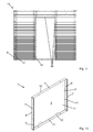
- an inventive structural element 1 which comprises a base body 2, which in turn has a rectangular front side 3 and a back side 4 (cf. Fig. 4 ) having.
- the front side 3 has a width 16 and a height 17, cf. Fig. 3 , wherein in the illustrated embodiment, the width 16 greater than the height 17 fails.
- the width 16 is typically 900 mm to 1000 mm and the height 17 is typically 750 mm.
- the height 17 may also have other values for raised beds 13, in particular it is adaptable to the size of the user and is usually in a range between 450 mm (for children) and 800 mm (for adults).
- the height 17 drops correspondingly lower and is usually in the range of 250 mm to 300 mm.
- the height 17 correspondingly larger and is in a range between 2000 mm and 2400 mm, typically 2200 mm.
- the front 3 has an edge 5, which is formed by four edges. On two opposite edges positioning strips 6 are arranged, which form a right angle with the plane of the front 3.
- Fig. 2 shows a plan view of a positioning strip 6, in which it can be clearly seen that the positioning strip 6 has a side edge 9, which is seen from the front side 3 in the direction normal to the plane of the front side 3 spaced. That is, the side edge 9 has the front side 3 at a normal distance greater than zero. The corresponding maximum normal distance from points on the side edge 9 to the front side 3 is equal to a width 18 of the positioning bar 6. A typical value for the width 18 would be 47 mm.
- the positioning strip 6 is provided with recesses 7, which are arranged along the side edge 9 so that a serrated or comb-like structure of the side edge 9 is given.
- the recesses 7 are used to position wooden slats 8 by each wooden slat 8 is placed or placed both in a recess 7 of a positioning bar 6 and in a recess 7 of the other positioning bar 6.
- Fig. 12 shows an alternative embodiment of the structural element 1 according to the invention, which is characterized by recesses 7, which are designed as completely edged recesses 7 and holes in the positioning strips 6.
- the wooden battens 8 must be guided with one end in the direction of their longitudinal extent through the recesses 7 in order to be positioned.
- a possible fixation of the wooden slats 8 then serves only to prevent movement of the respective wooden slat 8 in the direction of its longitudinal extent.
- mounting beams 12 made of wood with fastening means 21, such as nails or chipboard screws.
- fastening means 21 such as nails or chipboard screws.
- the mounting bars 12 are fixed to the front side 3 by means of screws 20.
- the base body 2 bores 11, which are arranged along a straight line on the front side 3, parallel to the positioning strips 6.
- the structural element 1 also has two boundary strips 10, which are each arranged along the edges, along which no positioning strips 6 are arranged. Accordingly, the positioning strips 6 and the boundary strips 10 at right angles to each other.
- the boundary strips 10 are also bent as well as the positioning strips 6 at a right angle out of the plane of the front side 3, ie the boundary strips 10 close with the plane of the front 3 also a right angle.
- the boundary strips 10 have holes 11, which facilitate the simple installation of a cover strip 22 by means of screws 20 enable. But it must not be mounted on both boundary strips 10 such end strips 22.
- the bores 11 of the boundary strip 10 can also be used for fixing the structural element 1 on a frame (not shown) or for connecting two structural elements 1 arranged one above the other, which abut one another with a respective boundary strip 10 (not shown).
- the boundary strips 10 have a width 19, which in Fig. 4 is clearly visible and the same size as the width 18 of the positioning strips 6 fails.
- the mounted on the bordering bar 10 graduation batten 22 can of course have larger dimensions and project beyond the boundary strip 10. This is in the side view of Fig. 7 Particularly well recognizable, where the final lath 10 projects beyond not only the boundary strip 10 but also the wooden slats 8.
- Fig. 8 shows for better illustration also an axonometric view of the wood slats 8 clad structural element. 1
- the structural element 1 is made of metal and in one piece.
- the complete structural element 1 is punched out of a metal plate in unwound form, cf. Fig. 5 , That is, in principle, in one step, the base body 2, the positioning strips 6 together with recesses 7 and the boundary strips 10 and all holes 11 are made. Then the positioning strips 6 and the boundary strips 10 only have to be tilted to the in Fig. 1 completed structural element 1 finished.
- Fig. 5 shows that the positioning strips have 6 holes 11. These are important for the production of space-forming structures by the structural elements 1 according to the invention.
- two structural elements 1 can by taking advantage of the holes 11 in the Positioning strips 6 are connected by screwing 15 of their abutting positioning strips 6 together, as in Fig. 9 is illustrated. In this way, a plurality of structural elements 1 can be connected in one direction to a wall.
- This in Fig. 9 raised bed 13 shown consists of four walls, which are arranged around a rectangular base. To connect each two walls or structural elements 1, which are at right angles to each other, are - for the in Fig. 9 shown raised bed 13 a total of four - rectangular angle connecting elements 23 is provided. Accordingly, in each case a positioning strip 6 of the structural elements 1 to be connected at right angles to each other is connected to the angle connecting element 23 by means of screw connection 24, so that the in Fig. 9 shown raised bed 13 results.
- Fig. 10 shows the same raised bed 13, but with mounted wooden slats 8 and end slats 22nd
- FIGS. 9 and 10 show that in FIGS. 9 and 10
- the structural elements 1 are connected to the door frame element 25 by positioning strips 6 and / or boundary strips 10 are fastened by means of screw 26 on the door frame element 25.
- the holes 11 in the positioning strips 6 and / or boundary strips 10 are used.
- the door frame element 25 has for this also appropriate holes on (in Fig. 11 not visible).
Landscapes
- Engineering & Computer Science (AREA)
- Architecture (AREA)
- Civil Engineering (AREA)
- Structural Engineering (AREA)
- Life Sciences & Earth Sciences (AREA)
- Mining & Mineral Resources (AREA)
- Wood Science & Technology (AREA)
- General Life Sciences & Earth Sciences (AREA)
- Paleontology (AREA)
- General Engineering & Computer Science (AREA)
- Grates (AREA)
Applications Claiming Priority (1)
| Application Number | Priority Date | Filing Date | Title |
|---|---|---|---|
| ATGM169/2012U AT13083U1 (de) | 2012-04-20 | 2012-04-20 | Strukturelement für raumbildende Aufbauten im Gartenbereich |
Publications (2)
| Publication Number | Publication Date |
|---|---|
| EP2653616A2 true EP2653616A2 (fr) | 2013-10-23 |
| EP2653616A3 EP2653616A3 (fr) | 2017-05-03 |
Family
ID=48222666
Family Applications (1)
| Application Number | Title | Priority Date | Filing Date |
|---|---|---|---|
| EP13164726.5A Withdrawn EP2653616A3 (fr) | 2012-04-20 | 2013-04-22 | Elément structurel pour des constructions paysagères dans le domaine de la jardinerie |
Country Status (2)
| Country | Link |
|---|---|
| EP (1) | EP2653616A3 (fr) |
| AT (1) | AT13083U1 (fr) |
Cited By (1)
| Publication number | Priority date | Publication date | Assignee | Title |
|---|---|---|---|---|
| CN104404968A (zh) * | 2014-12-10 | 2015-03-11 | 中建三局第一建设工程有限责任公司 | 基坑内支撑梁拆除装置及基坑内支撑梁拆除方法 |
Family Cites Families (3)
| Publication number | Priority date | Publication date | Assignee | Title |
|---|---|---|---|---|
| DE102004035351A1 (de) * | 2003-08-12 | 2005-04-14 | Franz Hof Gmbh | Bauteil zur Errichtung von Stützelementen |
| DE202004007559U1 (de) * | 2004-05-07 | 2004-07-22 | Heinz Burkholz Gmbh | Hochbeetbehälter |
| CH703298A1 (de) * | 2010-06-02 | 2011-12-15 | Felix Cadonau | Halteprofil. |
-
2012
- 2012-04-20 AT ATGM169/2012U patent/AT13083U1/de not_active IP Right Cessation
-
2013
- 2013-04-22 EP EP13164726.5A patent/EP2653616A3/fr not_active Withdrawn
Non-Patent Citations (1)
| Title |
|---|
| None |
Cited By (1)
| Publication number | Priority date | Publication date | Assignee | Title |
|---|---|---|---|---|
| CN104404968A (zh) * | 2014-12-10 | 2015-03-11 | 中建三局第一建设工程有限责任公司 | 基坑内支撑梁拆除装置及基坑内支撑梁拆除方法 |
Also Published As
| Publication number | Publication date |
|---|---|
| AT13083U1 (de) | 2013-05-15 |
| EP2653616A3 (fr) | 2017-05-03 |
Similar Documents
| Publication | Publication Date | Title |
|---|---|---|
| DE1609784C3 (fr) | ||
| AT518814B1 (de) | Zaunsystem sowie Montageverfahren für ein Zaunsystem | |
| EP2754784A1 (fr) | Système de construction d'une paroi de protection contre le vent et/ou contre les regards | |
| AT509484B1 (de) | Haltevorrichtung zum verbinden von profilen zu einem flächigen wandelement | |
| DE102017104344B3 (de) | Begrenzung für ein Hochbeet | |
| DE102020100493A1 (de) | Torpfosten für Sichtschutz | |
| DE2814713A1 (de) | Zerlegbare trennwand | |
| EP2653616A2 (fr) | Elément structurel pour des constructions paysagères dans le domaine de la jardinerie | |
| DE102011102981B4 (de) | Sicht- und Windschutz für Zäune und Flächenabtrennungen | |
| EP2083127B1 (fr) | Tête de liaison et système destiné à l'établissement de structures | |
| DE102005008645A1 (de) | Eckverbinder zum Verbinden zweier Profilleisten | |
| DE102005048111A1 (de) | Eckverbinder zum Verbinden zweier Hohl-Profilleisten | |
| DE10323347B4 (de) | Treppe und Tragkonstruktion einer Treppe | |
| DE102004022152B4 (de) | Nut- und Federpaneel | |
| CH721511A2 (de) | Befestigungselement, Verfahren zur Herstellung einer Wand sowie zugehöriges Set | |
| DE3041173C2 (de) | Fischunterstand für Uferverbauungen aus Holzlamellen | |
| DE102014104694A1 (de) | Baukonstruktion | |
| EP1589158A2 (fr) | Dispositif de fixation d'éléments de façade | |
| DE10013703C2 (de) | Vorrichtung zur Schaustellung von Produkten für das Bauwesen | |
| DE102023119771A1 (de) | Als Doppelstabmatte ausgebildetes Zaunelement mit Sichtschutz, Befestigungselement für Sichtschutz und Verfahren zur Befestigung des Sichtschutzes an einem solchen Zaunelement | |
| DE102020101353A1 (de) | Stützelement | |
| DE2548616A1 (de) | Vorrichtung zur befestigung zweier waagerecht uebereinander liegenden, aus einzelplatten bestehenden plattenreihen an einer gebaeudefassade | |
| DE202015100108U1 (de) | Haltevorrichtung für die Enden zwischen die Gitterstäbe eines Stabgitterelementes eingeflochtener Wind- und/oder Sichtschutzprofile | |
| DE202012101581U1 (de) | Zaun | |
| DE202009015200U1 (de) | Balkonkonstruktion |
Legal Events
| Date | Code | Title | Description |
|---|---|---|---|
| PUAI | Public reference made under article 153(3) epc to a published international application that has entered the european phase |
Free format text: ORIGINAL CODE: 0009012 |
|
| AK | Designated contracting states |
Kind code of ref document: A2 Designated state(s): AL AT BE BG CH CY CZ DE DK EE ES FI FR GB GR HR HU IE IS IT LI LT LU LV MC MK MT NL NO PL PT RO RS SE SI SK SM TR |
|
| AX | Request for extension of the european patent |
Extension state: BA ME |
|
| PUAL | Search report despatched |
Free format text: ORIGINAL CODE: 0009013 |
|
| AK | Designated contracting states |
Kind code of ref document: A3 Designated state(s): AL AT BE BG CH CY CZ DE DK EE ES FI FR GB GR HR HU IE IS IT LI LT LU LV MC MK MT NL NO PL PT RO RS SE SI SK SM TR |
|
| AX | Request for extension of the european patent |
Extension state: BA ME |
|
| RIC1 | Information provided on ipc code assigned before grant |
Ipc: E04F 13/08 20060101ALI20170329BHEP Ipc: E02D 17/04 20060101AFI20170329BHEP Ipc: E02D 17/20 20060101ALI20170329BHEP |
|
| STAA | Information on the status of an ep patent application or granted ep patent |
Free format text: STATUS: THE APPLICATION IS DEEMED TO BE WITHDRAWN |
|
| 18D | Application deemed to be withdrawn |
Effective date: 20171104 |