EP2653656A2 - Aube de turbine ayant un revêtement de surface portante d'épaisseur constante - Google Patents
Aube de turbine ayant un revêtement de surface portante d'épaisseur constante Download PDFInfo
- Publication number
- EP2653656A2 EP2653656A2 EP13171827.2A EP13171827A EP2653656A2 EP 2653656 A2 EP2653656 A2 EP 2653656A2 EP 13171827 A EP13171827 A EP 13171827A EP 2653656 A2 EP2653656 A2 EP 2653656A2
- Authority
- EP
- European Patent Office
- Prior art keywords
- blade
- support structure
- skin
- framework
- turbine blade
- Prior art date
- Legal status (The legal status is an assumption and is not a legal conclusion. Google has not performed a legal analysis and makes no representation as to the accuracy of the status listed.)
- Withdrawn
Links
- 238000013016 damping Methods 0.000 claims abstract description 22
- 239000007789 gas Substances 0.000 description 17
- 238000001816 cooling Methods 0.000 description 11
- 230000001186 cumulative effect Effects 0.000 description 6
- PXHVJJICTQNCMI-UHFFFAOYSA-N Nickel Chemical compound [Ni] PXHVJJICTQNCMI-UHFFFAOYSA-N 0.000 description 4
- 229910000990 Ni alloy Inorganic materials 0.000 description 3
- 239000000463 material Substances 0.000 description 3
- 239000012809 cooling fluid Substances 0.000 description 2
- 238000012986 modification Methods 0.000 description 2
- 230000004048 modification Effects 0.000 description 2
- 229910052759 nickel Inorganic materials 0.000 description 2
- 229910000601 superalloy Inorganic materials 0.000 description 2
- 229910004696 Ti—Cu—Ni Inorganic materials 0.000 description 1
- 238000005266 casting Methods 0.000 description 1
- 230000000694 effects Effects 0.000 description 1
- 238000010894 electron beam technology Methods 0.000 description 1
- 229910001026 inconel Inorganic materials 0.000 description 1
- 229910001063 inconels 617 Inorganic materials 0.000 description 1
- 229910000816 inconels 718 Inorganic materials 0.000 description 1
- 238000000034 method Methods 0.000 description 1
- 238000004663 powder metallurgy Methods 0.000 description 1
Images


Classifications
-
- F—MECHANICAL ENGINEERING; LIGHTING; HEATING; WEAPONS; BLASTING
- F01—MACHINES OR ENGINES IN GENERAL; ENGINE PLANTS IN GENERAL; STEAM ENGINES
- F01D—NON-POSITIVE DISPLACEMENT MACHINES OR ENGINES, e.g. STEAM TURBINES
- F01D5/00—Blades; Blade-carrying members; Heating, heat-insulating, cooling or antivibration means on the blades or the members
- F01D5/12—Blades
- F01D5/14—Form or construction
- F01D5/147—Construction, i.e. structural features, e.g. of weight-saving hollow blades
-
- F—MECHANICAL ENGINEERING; LIGHTING; HEATING; WEAPONS; BLASTING
- F01—MACHINES OR ENGINES IN GENERAL; ENGINE PLANTS IN GENERAL; STEAM ENGINES
- F01D—NON-POSITIVE DISPLACEMENT MACHINES OR ENGINES, e.g. STEAM TURBINES
- F01D11/00—Preventing or minimising internal leakage of working-fluid, e.g. between stages
- F01D11/005—Sealing means between non relatively rotating elements
- F01D11/006—Sealing the gap between rotor blades or blades and rotor
- F01D11/008—Sealing the gap between rotor blades or blades and rotor by spacer elements between the blades, e.g. independent interblade platforms
-
- F—MECHANICAL ENGINEERING; LIGHTING; HEATING; WEAPONS; BLASTING
- F01—MACHINES OR ENGINES IN GENERAL; ENGINE PLANTS IN GENERAL; STEAM ENGINES
- F01D—NON-POSITIVE DISPLACEMENT MACHINES OR ENGINES, e.g. STEAM TURBINES
- F01D5/00—Blades; Blade-carrying members; Heating, heat-insulating, cooling or antivibration means on the blades or the members
- F01D5/12—Blades
- F01D5/14—Form or construction
- F01D5/16—Form or construction for counteracting blade vibration
-
- F—MECHANICAL ENGINEERING; LIGHTING; HEATING; WEAPONS; BLASTING
- F01—MACHINES OR ENGINES IN GENERAL; ENGINE PLANTS IN GENERAL; STEAM ENGINES
- F01D—NON-POSITIVE DISPLACEMENT MACHINES OR ENGINES, e.g. STEAM TURBINES
- F01D5/00—Blades; Blade-carrying members; Heating, heat-insulating, cooling or antivibration means on the blades or the members
- F01D5/30—Fixing blades to rotors; Blade roots ; Blade spacers
- F01D5/3007—Fixing blades to rotors; Blade roots ; Blade spacers of axial insertion type
-
- F—MECHANICAL ENGINEERING; LIGHTING; HEATING; WEAPONS; BLASTING
- F05—INDEXING SCHEMES RELATING TO ENGINES OR PUMPS IN VARIOUS SUBCLASSES OF CLASSES F01-F04
- F05D—INDEXING SCHEME FOR ASPECTS RELATING TO NON-POSITIVE-DISPLACEMENT MACHINES OR ENGINES, GAS-TURBINES OR JET-PROPULSION PLANTS
- F05D2230/00—Manufacture
- F05D2230/20—Manufacture essentially without removing material
- F05D2230/23—Manufacture essentially without removing material by permanently joining parts together
- F05D2230/232—Manufacture essentially without removing material by permanently joining parts together by welding
- F05D2230/233—Electron beam welding
-
- F—MECHANICAL ENGINEERING; LIGHTING; HEATING; WEAPONS; BLASTING
- F05—INDEXING SCHEMES RELATING TO ENGINES OR PUMPS IN VARIOUS SUBCLASSES OF CLASSES F01-F04
- F05D—INDEXING SCHEME FOR ASPECTS RELATING TO NON-POSITIVE-DISPLACEMENT MACHINES OR ENGINES, GAS-TURBINES OR JET-PROPULSION PLANTS
- F05D2230/00—Manufacture
- F05D2230/20—Manufacture essentially without removing material
- F05D2230/23—Manufacture essentially without removing material by permanently joining parts together
- F05D2230/232—Manufacture essentially without removing material by permanently joining parts together by welding
- F05D2230/237—Brazing
-
- F—MECHANICAL ENGINEERING; LIGHTING; HEATING; WEAPONS; BLASTING
- F05—INDEXING SCHEMES RELATING TO ENGINES OR PUMPS IN VARIOUS SUBCLASSES OF CLASSES F01-F04
- F05D—INDEXING SCHEME FOR ASPECTS RELATING TO NON-POSITIVE-DISPLACEMENT MACHINES OR ENGINES, GAS-TURBINES OR JET-PROPULSION PLANTS
- F05D2230/00—Manufacture
- F05D2230/50—Building or constructing in particular ways
- F05D2230/54—Building or constructing in particular ways by sheet metal manufacturing
-
- F—MECHANICAL ENGINEERING; LIGHTING; HEATING; WEAPONS; BLASTING
- F05—INDEXING SCHEMES RELATING TO ENGINES OR PUMPS IN VARIOUS SUBCLASSES OF CLASSES F01-F04
- F05D—INDEXING SCHEME FOR ASPECTS RELATING TO NON-POSITIVE-DISPLACEMENT MACHINES OR ENGINES, GAS-TURBINES OR JET-PROPULSION PLANTS
- F05D2230/00—Manufacture
- F05D2230/60—Assembly methods
-
- F—MECHANICAL ENGINEERING; LIGHTING; HEATING; WEAPONS; BLASTING
- F05—INDEXING SCHEMES RELATING TO ENGINES OR PUMPS IN VARIOUS SUBCLASSES OF CLASSES F01-F04
- F05D—INDEXING SCHEME FOR ASPECTS RELATING TO NON-POSITIVE-DISPLACEMENT MACHINES OR ENGINES, GAS-TURBINES OR JET-PROPULSION PLANTS
- F05D2240/00—Components
- F05D2240/80—Platforms for stationary or moving blades
-
- F—MECHANICAL ENGINEERING; LIGHTING; HEATING; WEAPONS; BLASTING
- F05—INDEXING SCHEMES RELATING TO ENGINES OR PUMPS IN VARIOUS SUBCLASSES OF CLASSES F01-F04
- F05D—INDEXING SCHEME FOR ASPECTS RELATING TO NON-POSITIVE-DISPLACEMENT MACHINES OR ENGINES, GAS-TURBINES OR JET-PROPULSION PLANTS
- F05D2250/00—Geometry
- F05D2250/70—Shape
- F05D2250/71—Shape curved
-
- F—MECHANICAL ENGINEERING; LIGHTING; HEATING; WEAPONS; BLASTING
- F05—INDEXING SCHEMES RELATING TO ENGINES OR PUMPS IN VARIOUS SUBCLASSES OF CLASSES F01-F04
- F05D—INDEXING SCHEME FOR ASPECTS RELATING TO NON-POSITIVE-DISPLACEMENT MACHINES OR ENGINES, GAS-TURBINES OR JET-PROPULSION PLANTS
- F05D2260/00—Function
- F05D2260/20—Heat transfer, e.g. cooling
-
- F—MECHANICAL ENGINEERING; LIGHTING; HEATING; WEAPONS; BLASTING
- F05—INDEXING SCHEMES RELATING TO ENGINES OR PUMPS IN VARIOUS SUBCLASSES OF CLASSES F01-F04
- F05D—INDEXING SCHEME FOR ASPECTS RELATING TO NON-POSITIVE-DISPLACEMENT MACHINES OR ENGINES, GAS-TURBINES OR JET-PROPULSION PLANTS
- F05D2260/00—Function
- F05D2260/96—Preventing, counteracting or reducing vibration or noise
Definitions
- the present invention relates to turbine blades for a gas turbine wherein the blades comprise a support structure and an outer airfoil skin having a generally constant thickness along a radial direction.
- Some turbine blades for use in gas turbines employ load-bearing airfoil sidewalls, in which a cumulative centrifugal loading of the blade is carried radially inwardly via the airfoil sidewalls.
- the thicknesses of radially outermost portions of the airfoil sidewalls determine the thicknesses of radially innermost portions of the airfoil sidewalls near a root of the blade.
- a turbine blade for a gas turbine comprising: a support structure comprising a base defining a root of the blade and a framework extending radially outwardly from the base, and an outer skin coupled to the support structure framework such that the skin does not transfer a substantial portion of cumulative blade centrifugal loads inwardly to the root.
- the skin has a generally constant thickness along substantially the entire radial extent thereof.
- the framework and the skin define an airfoil of the blade.
- the support structure framework may comprise a plurality of spars extending radially outwardly from the base and a plurality of stringers extending between the spars.
- the support structure may further comprise a plurality of first tabs extending away from a leading spar and a plurality of second tabs extending away from a trailing spar.
- the skin may be coupled to the spars, the stringers and the first and second tabs.
- Cooling openings may be provided in the spars and the stringers.
- a tip cap may be coupled to the spars.
- the turbine blade may further comprise a damping element extending through openings provided in the stringers.
- the damping element comprising at least one damping bulb making contact with and extending between opposing sections of the skin.
- the damping bulb damps vibrations in the skin.
- the turbine blade may further comprise at least one platform section, non-integral with and located adjacent to the airfoil.
- the blade root may be mounted to a disk and the platform section may be coupled to the disk, such as by a bolt.
- the skin may have a thickness falling within a range of from about 0.010 inch to about 0.040 inch.
- a thickness of the support structure framework may become smaller in a radial direction from a first end adjacent the base to a second end opposite the first end.
- a turbine blade for a gas turbine comprising: a support structure comprising a base defining a root of the blade and a framework extending radially outwardly from the base; a skin coupled to the support structure framework, the framework and the skin defining an airfoil of the blade; and a damping element extending through openings provided in the support structure framework.
- the damping element may comprise a rod having at least one member making contact with and extending between opposing sections of the skin. The member may damp vibrations in the skin.
- the at least one member may comprise at least one bulb.
- a turbine blade for a gas turbine mounted to a rotor disk comprising: a support structure comprising a base defining a curved root of the blade and a framework extending radially outwardly from the base; a skin coupled to the support structure framework, the framework and the skin defining a curved airfoil of the blade; and at least one curved platform section located adjacent to the airfoil and coupled to the rotor disk.
- the blade root may be mounted to a disk and the platform section may be coupled to the disk.
- the platform section may be bolted to the disk at one location on the platform and further coupled to the disk via a non-bolted mechanical connection at another location on the platform.
- the at least one platform section may comprise first and second platform sections mounted on opposing sides of the airfoil.
- the root, airfoil and platform may be curved in an axial and circumferential plane.
- a blade 10 constructed in accordance with an embodiment of the present invention is illustrated.
- the blade 10 is adapted to be used in a gas turbine (not shown) of a gas turbine engine (not shown).
- a gas turbine within the gas turbine are a series of rows of stationary vanes and rotating blades. Typically, there are four rows of blades in a gas turbine. It is contemplated that the blade 10 illustrated in Fig. 10 may define the blade configuration for a fourth row of blades in the gas turbine.
- the turbine blades 10 are coupled to a shaft and disc assembly 20.
- a portion 22A of a disc 22 of the shaft and disc assembly 20 is illustrated in Fig. 10 .
- Hot working gases from a combustor (not shown) in the gas turbine engine travel to the rows of blades. As the working gases expand through the gas turbine, the working gases cause the blades, and therefore the shaft and disc assembly 20, to rotate.
- Each blade 10 forming the fourth row of blades may be constructed in the same manner as blade 10 discussed herein and illustrated in Fig. 10 .
- the turbine blade 10 is considered larger than a typical turbine blade as it comprises an airfoil 12 which may have a length L A of about 750 mm, see Fig. 10 .
- the airfoil 12 may alternatively have other lengths.
- the blade 10 is also believed to be capable of rotating with the shaft and disc assembly 20 at a speed of up to about 3600 RPM. It is believed that the blade 10, due to its size and capability of being rotated at high speeds, improves the overall efficiency of the turbine in which it is used.
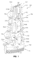
- the turbine blade 10 comprises a curved support structure 100 comprising a base 102 defining a curved root 14 of the blade 10 and a curved framework 104 extending radially outwardly from the base 102, see Figs. 1 and 2 .
- the base 102 and framework 104 are integrally formed together via a casting process from a material such as a cast nickel alloy, one example of which is Inconel 738.
- the support structure 100 may also be formed via a powder metallurgy process using a nickel-based super alloy disk material, one example of which is Inconel 718.
- the support structure 100 may be plated with braze material, such as Ti-Cu-Ni.
- the support structure framework 104 comprises, in the illustrated embodiment, leading, intermediate and trailing spars 106A-106C, respectfully, extending radially outwardly from the base 102 and a plurality of stringers 108 extending transversely between the spars 106A-106C.
- the support structure framework 104 further comprises a plurality of first tabs 110 extending away from the leading spar 106A and a plurality of second tabs 112 extending away from the trailing spar 106C.
- a thickness T of the support structure framework 104 may become smaller in a radial direction from a first end 204A adjacent the base 102 to a second upper end 204B, see Fig. 1 .
- the turbine blade 10 further comprises an outer skin 120 coupled to the support structure framework 104, wherein the skin 120 has an upper edge 120A and a lower edge 120B, see Figs. 1 and 10 .
- the outer skin 120 is preferably formed from a nickel super alloy such as Inconel 617 or Haynes 230, or an oxide dispersed nickel alloy such as MA 956.
- the outer skin 120 is also preferably cut from a sheet flat rolled to a minimum practical thickness falling with a range, such as from about 0.010 inch to about 0.040 inch.
- the outer skin 120 comprises a suction sidewall sheet or section 120C and a pressure sidewall sheet or section 120D, see Fig. 10 .
- the suction sidewall sheet 120C and the pressure sidewall sheet 120D are preferably cut from a sheet flat rolled to a minimum practical thickness falling with a range, such as from about 0.010 inch to about 0.040 inch.
- Cooling holes 120E are then laser cut or trepanned into the sheets 120C and 120, see Fig. 5 .
- the suction and pressure sidewall sheets 120C and 120D are hot formed via dies to a required shape defined by the support structure framework 104.
- the suction sidewall 120C has a convex shape and the pressure sidewall 120D has a concave shape.
- a leading edge portion 220C of the suction sheet 120C and a leading edge portion 220D of the pressure sheet 120D are then electron beam welded along substantially the entire radial extent of the sheets 120C and 120D.
- the weld 220 is machined and inspected.
- the welded suction and pressure sheets 120C and 120D are then fitted over the support structure framework 104 and brazed to the support structure framework 104. Thereafter, a trailing edge portion 320C of the suction sheet 120C and a trailing edge portion 320D of the pressure sheet 120D, see Fig. 4 , are brazed together along substantially the entire radial extent of the sheets 120C and 120D.
- a tip cap 300 having cooling fluid holes 301 may be riveted and/or brazed to the upper end 204B of the support structure framework 104. The tip cap 300 is then brazed near the upper edge 120A of the outer skin 120 for outer skin vibration control.
- the outer skin 120 is intended to transfer gas turning loads to the support structure framework 104, but is not intended to transfer cumulative centrifugal loads for the blade radially inward to the root 12. Rather, the framework 104 functions to carry the cumulative blade centrifugal loads radially inward to the root 12. Hence, the number and size of the framework spars, stringers and tabs may vary so as to accommodate the cumulative centrifugal loads for a given blade design. Because the outer skin 120 is not intended to transfer cumulative centrifugal loads radially inwardly, it is believed that the outer skin 120 can be made thinner and have a substantially constant thickness, such as along its entire extent in the radial direction.
- First cooling openings 206A are provided in the trailing spar 106C, second cooling openings 208 are provided in the stringers 108 and cooling recesses 210 are provided in the first tabs 110, see Figs. 1 and 2 .
- Input cooling bores 102A are formed in the base 102.
- cooling fluid such as air from the compressor of the gas turbine engine, is circulated internally within the blade 10 through the cooling bores 102A, the first and second cooling openings 206A and 208 and the cooling recesses 210 and exits the blade 10 via the cooling holes 120E in the outer skin 120 and the cooling holes 301 in the tip cap 300.
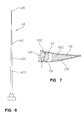
- the turbine blade 10 may further comprise a damping element 40 comprising a rod 40A and first, second and third members, such as first, second and third damping bulbs 40B-40D, integral with the rod 40A.
- the damping element 40 may be formed from a lathe-turned Nickel alloy.
- the damping element rod 40A and bulbs 40B-40D extend through openings 104A provided in the support structure framework 104.
- Each damping bulb 40B-40D has a thickness or diameter substantially equal to or slightly larger than a distance D between adjacent portions of the opposing suction sidewall section 120C and pressure sidewall section 120D so as to make contact with the sidewall sections 120C and 120D, see Fig. 7 .
- the damping bulbs 40B-40D function to frictionally damp vibrations in the outer skin 120.
- the turbine blade 10 further comprises a curved platform 50, which, in the illustrated embodiment, is non-integral with and located adjacent to the airfoil 12 and root 14.
- the platform 50 comprises first and second curved platform sections 52 and 54, respectively, coupled to the disk 22 of the shaft and disc assembly 20 on opposing sides of the airfoil 12, see Fig. 10 .
- the blade root 14 is also mounted to the disk 22, see Fig. 10 .
- the first curved platform section 52 comprises an upper section 150, first and second hooks 152A and 152B and a flange 154 provided with a bore 154A, see Figs. 8-10 .
- the disk 22 is provided with a first hook 22A that interlocks with the first platform section first hook 152A and a second hook 22B that interlocks with the first platform section second hook 152B.
- the disk further comprises a first flange 22C that comprises a bore 22D.
- the flange 154 on the first platform section 52 is positioned adjacent to the disk flange 22C.
- a bolt 23A passes through the bores 22D and 154A in the flanges 22C and 154 as well as through a nut 23B coupled to the flange 154A so as to couple the first platform section 52 to the disk 22.
- the second curved platform section 54 comprises an upper section 160, first and second hooks 162A (only the first hook is shown in Fig. 10 ) and a flange (not shown) provided with a bore.
- the disk 22 is provided with a third hook (not shown) that interlocks with the second platform section first hook 162A and a fourth hook (not shown) that interlocks with the second platform section second hook.
- the disk 22 further comprises a second flange (not shown) that comprises a bore. The flange on the second platform section 54 is positioned adjacent to the disk second flange.
- a bolt passes through the bores in the disk second flange and the flange on the second platform section 54 as well as through a nut (not shown) coupled to the flange on the second platform section 54 so as to coupled the second platform section 54 to the disk 22.
- the root 14 is provided with a slot 14A that does not extend completely through the root 14.
- a damping seal pin may extend into the slot 14A so as to engage the root 14 and effect a frictional damping function.
- the root 14, airfoil 12 and platform 50 may be curved in an axial and circumferential plane, wherein the axial direction is designated by axis A, the radial direction is designated by axis R and the circumferential direction is designated by axis C in Fig. 10 .
Landscapes
- Engineering & Computer Science (AREA)
- Mechanical Engineering (AREA)
- General Engineering & Computer Science (AREA)
- Architecture (AREA)
- Turbine Rotor Nozzle Sealing (AREA)
Applications Claiming Priority (2)
| Application Number | Priority Date | Filing Date | Title |
|---|---|---|---|
| US12/540,430 US8292583B2 (en) | 2009-08-13 | 2009-08-13 | Turbine blade having a constant thickness airfoil skin |
| EP10759747.8A EP2464829B1 (fr) | 2009-08-13 | 2010-02-17 | Aube de turbine présentant une enveloppe de pale d'épaisseur constante |
Related Parent Applications (2)
| Application Number | Title | Priority Date | Filing Date |
|---|---|---|---|
| EP10759747.8A Division EP2464829B1 (fr) | 2009-08-13 | 2010-02-17 | Aube de turbine présentant une enveloppe de pale d'épaisseur constante |
| EP10759747.8 Division | 2010-02-17 |
Publications (2)
| Publication Number | Publication Date |
|---|---|
| EP2653656A2 true EP2653656A2 (fr) | 2013-10-23 |
| EP2653656A3 EP2653656A3 (fr) | 2017-04-05 |
Family
ID=43586713
Family Applications (3)
| Application Number | Title | Priority Date | Filing Date |
|---|---|---|---|
| EP13171837.1A Withdrawn EP2653657A3 (fr) | 2009-08-13 | 2010-02-17 | Aube de turbine ayant un revêtement de surface portante d'épaisseur constante |
| EP13171827.2A Withdrawn EP2653656A3 (fr) | 2009-08-13 | 2010-02-17 | Aube de turbine ayant un revêtement de surface portante d'épaisseur constante |
| EP10759747.8A Not-in-force EP2464829B1 (fr) | 2009-08-13 | 2010-02-17 | Aube de turbine présentant une enveloppe de pale d'épaisseur constante |
Family Applications Before (1)
| Application Number | Title | Priority Date | Filing Date |
|---|---|---|---|
| EP13171837.1A Withdrawn EP2653657A3 (fr) | 2009-08-13 | 2010-02-17 | Aube de turbine ayant un revêtement de surface portante d'épaisseur constante |
Family Applications After (1)
| Application Number | Title | Priority Date | Filing Date |
|---|---|---|---|
| EP10759747.8A Not-in-force EP2464829B1 (fr) | 2009-08-13 | 2010-02-17 | Aube de turbine présentant une enveloppe de pale d'épaisseur constante |
Country Status (3)
| Country | Link |
|---|---|
| US (1) | US8292583B2 (fr) |
| EP (3) | EP2653657A3 (fr) |
| WO (1) | WO2011019412A2 (fr) |
Families Citing this family (21)
| Publication number | Priority date | Publication date | Assignee | Title |
|---|---|---|---|---|
| US9470095B2 (en) * | 2012-04-24 | 2016-10-18 | United Technologies Corporation | Airfoil having internal lattice network |
| US9267380B2 (en) * | 2012-04-24 | 2016-02-23 | United Technologies Corporation | Airfoil including loose damper |
| US9453422B2 (en) | 2013-03-08 | 2016-09-27 | General Electric Company | Device, system and method for preventing leakage in a turbine |
| US10697303B2 (en) | 2013-04-23 | 2020-06-30 | United Technologies Corporation | Internally damped airfoiled component and method |
| US10227884B2 (en) | 2013-09-18 | 2019-03-12 | United Technologies Corporation | Fan platform with leading edge tab |
| US20170002661A1 (en) * | 2013-12-20 | 2017-01-05 | General Electric Technology Gmbh | Rotor blade or guide vane assembly |
| US9777574B2 (en) | 2014-08-18 | 2017-10-03 | Siemens Energy, Inc. | Method for repairing a gas turbine engine blade tip |
| WO2016195656A1 (fr) | 2015-06-02 | 2016-12-08 | Siemens Aktiengesellschaft | Système de fixation pour surface portante de turbine utilisable dans une turbine à gaz |
| US10563666B2 (en) * | 2016-11-02 | 2020-02-18 | United Technologies Corporation | Fan blade with cover and method for cover retention |
| US10450872B2 (en) * | 2016-11-08 | 2019-10-22 | Rolls-Royce Corporation | Undercut on airfoil coversheet support member |
| US10774653B2 (en) | 2018-12-11 | 2020-09-15 | Raytheon Technologies Corporation | Composite gas turbine engine component with lattice structure |
| US11371358B2 (en) | 2020-02-19 | 2022-06-28 | General Electric Company | Turbine damper |
| US11365636B2 (en) * | 2020-05-25 | 2022-06-21 | General Electric Company | Fan blade with intrinsic damping characteristics |
| US11739645B2 (en) | 2020-09-30 | 2023-08-29 | General Electric Company | Vibrational dampening elements |
| US11536144B2 (en) | 2020-09-30 | 2022-12-27 | General Electric Company | Rotor blade damping structures |
| US11634991B1 (en) * | 2022-01-12 | 2023-04-25 | General Electric Company | Vibration damping system for turbine nozzle or blade using elongated body and wire mesh member |
| US11834960B2 (en) * | 2022-02-18 | 2023-12-05 | General Electric Company | Methods and apparatus to reduce deflection of an airfoil |
| US12031453B1 (en) | 2022-12-22 | 2024-07-09 | General Electric Company | Component with spar assembly for a turbine engine |
| US12421856B2 (en) * | 2023-06-29 | 2025-09-23 | Ge Infrastructure Technology Llc | Damper element with flexible legs for vibration dampening system for turbine blade |
| US12553349B2 (en) * | 2023-06-29 | 2026-02-17 | Ge Infrastructure Technology Llc | Vibration dampening system including resonant-tuned elongated body for damper element(s) for turbine component |
| US12410720B2 (en) | 2023-11-02 | 2025-09-09 | General Electric Company | Turbine engine having a rotatable disk and a blade |
Family Cites Families (27)
| Publication number | Priority date | Publication date | Assignee | Title |
|---|---|---|---|---|
| US2873944A (en) * | 1952-09-10 | 1959-02-17 | Gen Motors Corp | Turbine blade cooling |
| US2879028A (en) * | 1954-03-31 | 1959-03-24 | Edward A Stalker | Cooled turbine blades |
| US2920866A (en) * | 1954-12-20 | 1960-01-12 | A V Roe Canada Ltd | Hollow air cooled sheet metal turbine blade |
| US2825530A (en) * | 1955-05-13 | 1958-03-04 | Eugene F Schum | Air-cooled, strut supported turbine blade |
| US3240468A (en) * | 1964-12-28 | 1966-03-15 | Curtiss Wright Corp | Transpiration cooled blades for turbines, compressors, and the like |
| US3567333A (en) * | 1969-01-31 | 1971-03-02 | Curtiss Wright Corp | Gas turbine blade |
| US3695778A (en) * | 1970-09-18 | 1972-10-03 | Trw Inc | Turbine blade |
| US4501053A (en) * | 1982-06-14 | 1985-02-26 | United Technologies Corporation | Method of making rotor blade for a rotary machine |
| US4604780A (en) * | 1983-02-03 | 1986-08-12 | Solar Turbines Incorporated | Method of fabricating a component having internal cooling passages |
| US4802823A (en) * | 1988-05-09 | 1989-02-07 | Avco Corporation | Stress relief support structures and assemblies |
| JPH0792002B2 (ja) * | 1991-12-26 | 1995-10-09 | ゼネラル・エレクトリック・カンパニイ | ガスタービンエンジン支柱用のダンパアセンブリ |
| GB9208409D0 (en) * | 1992-04-16 | 1992-06-03 | Rolls Royce Plc | Rotors for gas turbine engines |
| FR2698126B1 (fr) | 1992-11-18 | 1994-12-16 | Snecma | Aube creuse de soufflante ou compresseur de turbomachine. |
| US5820343A (en) * | 1995-07-31 | 1998-10-13 | United Technologies Corporation | Airfoil vibration damping device |
| US5609779A (en) * | 1996-05-15 | 1997-03-11 | General Electric Company | Laser drilling of non-circular apertures |
| US6050777A (en) * | 1997-12-17 | 2000-04-18 | United Technologies Corporation | Apparatus and method for cooling an airfoil for a gas turbine engine |
| US6158963A (en) * | 1998-02-26 | 2000-12-12 | United Technologies Corporation | Coated article and method for inhibiting frictional wear between mating titanium alloy substrates in a gas turbine engine |
| US6247896B1 (en) * | 1999-06-23 | 2001-06-19 | United Technologies Corporation | Method and apparatus for cooling an airfoil |
| GB2365078B (en) * | 2000-07-27 | 2004-04-21 | Rolls Royce Plc | A gas turbine engine blade |
| US6416280B1 (en) * | 2000-11-27 | 2002-07-09 | General Electric Company | One piece spinner |
| GB2391270B (en) * | 2002-07-26 | 2006-03-08 | Rolls Royce Plc | Turbomachine blade |
| GB2397855B (en) * | 2003-01-30 | 2006-04-05 | Rolls Royce Plc | A turbomachine aerofoil |
| GB2402716B (en) * | 2003-06-10 | 2006-08-16 | Rolls Royce Plc | A damped aerofoil structure |
| US7075296B2 (en) * | 2004-11-09 | 2006-07-11 | Siemens Power Generation, Inc. | Inspection carriage for turbine blades |
| US7300253B2 (en) * | 2005-07-25 | 2007-11-27 | Siemens Aktiengesellschaft | Gas turbine blade or vane and platform element for a gas turbine blade or vane ring of a gas turbine, supporting structure for securing gas turbine blades or vanes arranged in a ring, gas turbine blade or vane ring and the use of a gas turbine blade or vane ring |
| US7980817B2 (en) * | 2007-04-16 | 2011-07-19 | United Technologies Corporation | Gas turbine engine vane |
| US8202054B2 (en) | 2007-05-18 | 2012-06-19 | Siemens Energy, Inc. | Blade for a gas turbine engine |
-
2009
- 2009-08-13 US US12/540,430 patent/US8292583B2/en not_active Expired - Fee Related
-
2010
- 2010-02-17 EP EP13171837.1A patent/EP2653657A3/fr not_active Withdrawn
- 2010-02-17 EP EP13171827.2A patent/EP2653656A3/fr not_active Withdrawn
- 2010-02-17 WO PCT/US2010/024350 patent/WO2011019412A2/fr not_active Ceased
- 2010-02-17 EP EP10759747.8A patent/EP2464829B1/fr not_active Not-in-force
Non-Patent Citations (1)
| Title |
|---|
| None |
Also Published As
| Publication number | Publication date |
|---|---|
| EP2653657A3 (fr) | 2017-04-05 |
| EP2653656A3 (fr) | 2017-04-05 |
| EP2464829B1 (fr) | 2013-08-14 |
| WO2011019412A2 (fr) | 2011-02-17 |
| EP2653657A2 (fr) | 2013-10-23 |
| WO2011019412A3 (fr) | 2011-12-15 |
| EP2464829A2 (fr) | 2012-06-20 |
| US8292583B2 (en) | 2012-10-23 |
| US20110038734A1 (en) | 2011-02-17 |
Similar Documents
| Publication | Publication Date | Title |
|---|---|---|
| EP2464829B1 (fr) | Aube de turbine présentant une enveloppe de pale d'épaisseur constante | |
| EP2995777B1 (fr) | Anneau d'aube pour moteur à turbine à gaz | |
| US8403645B2 (en) | Turbofan flow path trenches | |
| EP1079074B1 (fr) | Aube statorique et stator pour une turbomachine | |
| US9863254B2 (en) | Turbine airfoil with local wall thickness control | |
| US7955054B2 (en) | Internally damped blade | |
| US10287902B2 (en) | Variable stator vane undercut button | |
| EP3032033B2 (fr) | Ensemble de vanne pour moteur de turbine à gaz | |
| US10577940B2 (en) | Turbomachine rotor blade | |
| US9869185B2 (en) | Rotating turbine component with preferential hole alignment | |
| KR20020083498A (ko) | 냉각 팁 슈라우드를 구비하는 터빈 블레이드를 포함하는터빈조립체 | |
| US20150204237A1 (en) | Turbine blade and method for enhancing life of the turbine blade | |
| EP3241989A1 (fr) | Section de turbine à gaz présentant une meilleure conception d'entretoise | |
| EP3596312B1 (fr) | Pales amorties ayant une résistance au flottement améliorée | |
| US11954408B2 (en) | Stacking of rotor blade aerofoil sections to adjust resonant frequencies | |
| US12270317B2 (en) | Airfoils for gas turbine engines | |
| JP6558827B2 (ja) | タービンブレードのミッドスパンシュラウド組立体 | |
| US11339668B2 (en) | Method and apparatus for improving cooling of a turbine shroud | |
| WO2025223726A1 (fr) | Agencement de montage | |
| EP3483397B1 (fr) | Treillis de rail de support pour moteurs à turbine à gaz |
Legal Events
| Date | Code | Title | Description |
|---|---|---|---|
| PUAI | Public reference made under article 153(3) epc to a published international application that has entered the european phase |
Free format text: ORIGINAL CODE: 0009012 |
|
| AC | Divisional application: reference to earlier application |
Ref document number: 2464829 Country of ref document: EP Kind code of ref document: P |
|
| AK | Designated contracting states |
Kind code of ref document: A2 Designated state(s): AT BE BG CH CY CZ DE DK EE ES FI FR GB GR HR HU IE IS IT LI LT LU LV MC MK MT NL NO PL PT RO SE SI SK SM TR |
|
| PUAL | Search report despatched |
Free format text: ORIGINAL CODE: 0009013 |
|
| AK | Designated contracting states |
Kind code of ref document: A3 Designated state(s): AT BE BG CH CY CZ DE DK EE ES FI FR GB GR HR HU IE IS IT LI LT LU LV MC MK MT NL NO PL PT RO SE SI SK SM TR |
|
| RIC1 | Information provided on ipc code assigned before grant |
Ipc: F01D 5/16 20060101ALI20170302BHEP Ipc: F01D 5/14 20060101AFI20170302BHEP |
|
| STAA | Information on the status of an ep patent application or granted ep patent |
Free format text: STATUS: THE APPLICATION HAS BEEN PUBLISHED |
|
| STAA | Information on the status of an ep patent application or granted ep patent |
Free format text: STATUS: THE APPLICATION IS DEEMED TO BE WITHDRAWN |
|
| 18D | Application deemed to be withdrawn |
Effective date: 20170901 |