EP2653715B1 - Tour pour une éolienne ainsi que le procédé de montage de cette tour - Google Patents
Tour pour une éolienne ainsi que le procédé de montage de cette tour Download PDFInfo
- Publication number
- EP2653715B1 EP2653715B1 EP12002718.0A EP12002718A EP2653715B1 EP 2653715 B1 EP2653715 B1 EP 2653715B1 EP 12002718 A EP12002718 A EP 12002718A EP 2653715 B1 EP2653715 B1 EP 2653715B1
- Authority
- EP
- European Patent Office
- Prior art keywords
- tower
- base flange
- installation
- upright columns
- flange
- Prior art date
- Legal status (The legal status is an assumption and is not a legal conclusion. Google has not performed a legal analysis and makes no representation as to the accuracy of the status listed.)
- Revoked
Links
Images
Classifications
-
- E—FIXED CONSTRUCTIONS
- E04—BUILDING
- E04H—BUILDINGS OR LIKE STRUCTURES FOR PARTICULAR PURPOSES; SWIMMING OR SPLASH BATHS OR POOLS; MASTS; FENCING; TENTS OR CANOPIES, IN GENERAL
- E04H12/00—Towers; Masts or poles; Chimney stacks; Water-towers; Methods of erecting such structures
- E04H12/02—Structures made of specified materials
- E04H12/08—Structures made of specified materials of metal
- E04H12/085—Details of flanges for tubular masts
-
- F—MECHANICAL ENGINEERING; LIGHTING; HEATING; WEAPONS; BLASTING
- F03—MACHINES OR ENGINES FOR LIQUIDS; WIND, SPRING, OR WEIGHT MOTORS; PRODUCING MECHANICAL POWER OR A REACTIVE PROPULSIVE THRUST, NOT OTHERWISE PROVIDED FOR
- F03D—WIND MOTORS
- F03D13/00—Assembly, mounting or commissioning of wind motors; Arrangements specially adapted for transporting wind motor components
- F03D13/10—Assembly of wind motors; Arrangements for erecting wind motors
-
- F—MECHANICAL ENGINEERING; LIGHTING; HEATING; WEAPONS; BLASTING
- F03—MACHINES OR ENGINES FOR LIQUIDS; WIND, SPRING, OR WEIGHT MOTORS; PRODUCING MECHANICAL POWER OR A REACTIVE PROPULSIVE THRUST, NOT OTHERWISE PROVIDED FOR
- F03D—WIND MOTORS
- F03D13/00—Assembly, mounting or commissioning of wind motors; Arrangements specially adapted for transporting wind motor components
- F03D13/20—Arrangements for mounting or supporting wind motors; Masts or towers for wind motors
-
- Y—GENERAL TAGGING OF NEW TECHNOLOGICAL DEVELOPMENTS; GENERAL TAGGING OF CROSS-SECTIONAL TECHNOLOGIES SPANNING OVER SEVERAL SECTIONS OF THE IPC; TECHNICAL SUBJECTS COVERED BY FORMER USPC CROSS-REFERENCE ART COLLECTIONS [XRACs] AND DIGESTS
- Y02—TECHNOLOGIES OR APPLICATIONS FOR MITIGATION OR ADAPTATION AGAINST CLIMATE CHANGE
- Y02E—REDUCTION OF GREENHOUSE GAS [GHG] EMISSIONS, RELATED TO ENERGY GENERATION, TRANSMISSION OR DISTRIBUTION
- Y02E10/00—Energy generation through renewable energy sources
- Y02E10/70—Wind energy
- Y02E10/72—Wind turbines with rotation axis in wind direction
-
- Y—GENERAL TAGGING OF NEW TECHNOLOGICAL DEVELOPMENTS; GENERAL TAGGING OF CROSS-SECTIONAL TECHNOLOGIES SPANNING OVER SEVERAL SECTIONS OF THE IPC; TECHNICAL SUBJECTS COVERED BY FORMER USPC CROSS-REFERENCE ART COLLECTIONS [XRACs] AND DIGESTS
- Y02—TECHNOLOGIES OR APPLICATIONS FOR MITIGATION OR ADAPTATION AGAINST CLIMATE CHANGE
- Y02E—REDUCTION OF GREENHOUSE GAS [GHG] EMISSIONS, RELATED TO ENERGY GENERATION, TRANSMISSION OR DISTRIBUTION
- Y02E10/00—Energy generation through renewable energy sources
- Y02E10/70—Wind energy
- Y02E10/728—Onshore wind turbines
Definitions
- the present invention relates to a tower for a wind turbine, which has a tower section which has an inwardly projecting foot flange at its end facing the foundation.
- the invention also relates to a method for erecting a tower for a wind energy plant.
- the towers for wind turbines according to the invention comprise towers designed for onshore or offshore construction.
- the construction anchored in the seabed on which the tower is built is subsequently referred to as the foundation.
- EP 1 933 029 A1 has become known a method for fixing elements within a tower of a wind turbine.
- the tower consists of various sections of metal, wherein the elements provided therein are attached to auxiliary carriers.
- the subcarriers should be attached to each tower section so that no weakening of the material is created.
- double-T beams are attached to an upper flange and a lower flange of the tower section and are parallel to the tower walls.
- a fixed bearing is provided, on which the carrier are fixed, while at the lower flange, a loose bearing is provided, which allows a displacement of the carrier in the longitudinal direction of the door.
- a tower for a wind turbine has become known in which a power module is arranged on a supporting structure.
- the supporting structure is based on the foundation of the wind energy plant.
- WO 2006/056196 is a wind turbine and a method for assembling it has become known in which stackable internals are stacked on top of each other, with the bottom-most internals are directly on the foundation.
- WO 2010/103114 A1 is a wind turbine with a lower tower section has become known in which an electrical equipment for the wind turbine is pre-assembled.
- the electrical units such as transformer, control cabinet, inverter, emergency and the like are attached to the tower walls.
- a tower for a wind power plant has become known, the installations of which are fastened in each case to an upper and a lower flange in the tower sections.
- the components carrying the electrical components are located on the foundation.
- WO 02/46552 A1 is a telescopically trained tower for large wind turbines known. During erection of the tower, tie rods are temporarily tensioned between upper and lower flanges of a tower section, along which another tower section can be raised.
- the invention has for its object to provide a tower for a wind turbine and a method for its establishment, in which without weakening the tower walls heavy electrical installations of the wind turbine can be safely and reliably pre-assembled.
- the tower according to the invention is provided and intended for a wind energy plant.
- the tower has a tower section which has an inwardly projecting foot flange at its end facing the foundation.
- the foot flange can be formed in one piece as well as in several parts. So are foot flanges, which are connected to a load distribution plate, foot flanges in the context of the invention.
- the tower installation according to the invention can be supported on the one-piece foot flange. Alternatively, the tower installation can be supported on the load distribution plate connected to the foot flange.
- a self-supporting tower installation for the tower section is provided which has at least three parallel and spaced from the tower wall extending stand and the stator interconnecting cross member.
- the stands are preferably evenly distributed over the circumference of the foot flange to form a self-supporting tower installation, which is fully supported on the gymnaslansch.
- the stands are mounted on the foot flange.
- the self-supporting tower installation is elevated on the base flange, without further, possibly weakening the tower wall connections between the tower installation and the tower wall.
- the invention is based on the recognition that even heavy components of a wind turbine can be safely and reliably installed in the tower by a freestanding and self-supporting tower installation. Connections with an upper flange or with the tower wall, which increase the effort for the assembly of the tower installation, can be omitted according to the invention.
- the space available in the tower section can be optimally utilized.
- tower structures that are placed directly on the foundation have a significantly smaller diameter than the tower. This is necessary in order to move the tower installation through the inwardly facing flanges of the tower section or to push the tower section over the standing on the foundation tower installation.
- the tower installation can be pre-assembled in the tower section and the available space can be used optimally.
- the ends of the uprights facing away from the base flange are free and not connected to the tower wall.
- the stands are held with their end attachments on the base flange alone by the cross member in position and can carry so large loads. Also, the use of a lot-bearing, which gives sufficient play for the stator at a possible deformation of the tower, can be omitted, since the stands are supported only on theticianflansch and otherwise run freely in the tower. Structurally weakening interventions in the tower wall can be avoided.
- the cross members are connected exclusively to the uprights or another cross member and not mounted in any form on the tower wall.
- the cross members are arranged horizontally between the uprights in order to form at least one platform in the tower installation.
- the tower installation on several superposed platforms on which the individual components can be made available to operating personnel.
- a platform arranged above the base flange is elevated by means of short uprights which support at least one cross member of the platform on the base flange.
- At least one damping element is arranged laterally between the tower installation and the inside of the tower wall.
- the damping element is attached to the tower installation.
- the damping element prevents vibrations from the tower wall, for example, by the operation of the wind turbine, are transmitted to the tower installation and set up in this components. Also, the transmission of vibrations from the tower installation on the tower section can be prevented by the damping element.
- the damping element is to distinguish whether this permanently establishes contact between the tower installation and the inside of the tower wall or whether it only comes into contact with the tower wall in vibrations with high amplitude and thus prevents the transmission of vibrations.
- the stands are preferably designed as a T-profile or as a double-T-profile.
- the stands have at their end pointing to the foot flange a load distribution plate, which is preferably equipped with holes to connect the stator to the base flange.
- the stands can also be equipped with a flange, via which the stand can be fastened to the foot flange.
- the flange can either be on the pointing to the tower flat side of the Resting foot flange or over this above, abut against the end face and be attached.
- the foot flange is formed integrally with the tower wall.
- the foot flange forms in this embodiment at the same time on its underside a bearing surface with which the tower section can be placed on a foundation body, another tower section or an adapter connecting the foundation body and the lower tower section.
- a base flange can be formed for example by a load distribution plate, which is arranged between the tower section and its support, for example a foundation body or an adapter.
- the inventive method is provided for the construction of a tower for a wind turbine.
- a method step the provision of a tower section is provided which has an inwardly projecting foot flange at one end.
- the stands are distributed over the circumference of the faced and at their foot ends on the faced on the teachingflansch the tower section in a subsequent step Fixed, allowing the self-supporting tower installation freely in the tower section on the foot flange is supported.
- the installation of a self-supporting and freestanding, only on the researchingflansch supporting tower installation offers the advantage that a weakening of the tower wall is avoided.
- the stands are connected to the cross members and the floor panels are mounted on the cross members to form platforms.
- the assembly of components in the tower installation and the construction of the tower for the wind turbine with the tower section, in which the components are already mounted in the tower installation are, for example, electrical components of the wind turbine, which can be arranged in the foot area of the tower.
- the assembled components are tested. In this way, errors in the connection of the components or errors in the components themselves can be detected early. The elimination of errors only at the place of construction of the tower, whether offshore or onshore, can be avoided.
- the tower section is provided standing upright, so that the base flange is located at the lower end of the tower section and the installation of the tower installation on the base flange in the upright tower section can take place.
- the foot flange may be integrally formed with the tower section, alternatively, it is also possible to connect, for example, a load distribution plate with the tower section and provide this as a foot flange for the elevation of the tower installation.
- the tower section is then transported upright to the erection site of the tower. This avoids that the freestanding tower installation in the tower section is incorrectly loaded or damaged.
- the components of one or more components mounted in the tower installation are preferably from the following group: generator, transformer, control cabinet and converter. These can also be electrically connected to each other in the tower and tested in whole or in part in their operation.
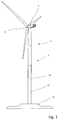
- Fig. 1 shows a wind turbine 1 with a tower 2 and a gondola arranged thereon 4.
- the drive train (not shown) of the wind turbine which is connected to the rotor 6.
- the Tower 2 consists of several stacked tower sections 10.
- the lowest tower section 10 stands on a schematically illustrated foundation body 13, which is for example wholly or partially embedded in the earth region. Alternatively, the lowermost tower section may also be connected to a foundation structure of an offshore foundation.
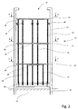
- Fig. 2 shows a tower section 10, which is connected via an adapter 11 with the foundation 13.
- a self-supporting tower installation 14 is arranged, which consists of several stands 16, 34.
- the uprights 16, 34 are supported on the base flange 26 of the tower section 10. They are arranged at a distance from the tower wall and connected to each other via cross members 18.
- the cross members 18 are connected to the uprights 16, 34 such that platforms 20, 22, 24 are formed.
- the platforms are accessible to each other via a ladder (not shown).
- On the cross members of each platform floor plates 28 are designed so that the entire platform is accessible.
- the bottom plates 28 protrude laterally beyond the uprights 16, 34 but are spaced from the inside of the tower wall.
- the platforms are used to install components (not shown) such as a transformer, a switchgear or an inverter.
- components such as a transformer, a switchgear or an inverter.
- the individual platforms are also connected by a cable guide in the vertical direction.
- damping elements 44 are provided on the uprights, which act between the tower installation and the inner wall of the section. By the damping elements 44, a transmission of vibrations between the tower installation and the tower wall is prevented.
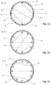
- the Figures 3a, 3b and 3c show cross sections along the lines AA, BB and CC.
- the sectional views show the arranged within the tower section 10 platforms 20, 22, 24 with the respectively associated uprights 16, 34 and the Cross beams 18 and floor panels 28.
- the self-supporting tower installation has twelve stands, of which four stands 34 extend to the bottom platform 20 and eight stands 16 to the top platform 24.
- the number of stands may be larger or smaller.
- the number of long and short uprights can be varied according to the loads to be absorbed by the platforms.
- Fig. 3a shows a bottom plate 28 which is supported on three cross members 18.
- a cross member 18 extends through the center of the tower and is fixed to two opposite uprights 16, while two further cross member 18 extend eccentrically and are secured to other uprights 16.
- the up to the upper platform 24 extending stand 16 are not evenly distributed over the circumference, so that the cross member 18 is not parallel to each other.
- Fig. 3b shows the stand 16 and the cross member 18 in the section along the line BB Fig. 2 ,
- the cross members with a different orientation from the overlying platform Fig. 3a arranged to distribute the load on other stand 16.
- Fig. 3c shows the section along the line CC Fig. 2 , wherein here the bottom plate 28 is supported only by two cross members 18.
- the middle cross member 28 may be omitted.
- the platform 20 is supported only by the stand 34.
- the uprights 34 do not extend to the other platforms 22 and 24, but support only the platform 20 for receiving particularly heavy loads relative to the base flange 26 from.
- the platform 20 additionally supported on the uprights 16 in the 2 o'clock, 4 o'clock, 8 o'clock and 11 o'clock positions.
- annular support (not shown) to the uprights so as to support the platforms better, especially in their edge region.
- the annular support may later be formed as a closed ring which is attached to all uprights or as a ring segment which is attached to a part of the stand.
- additional straps may be attached between the straps 18 to reduce the span.
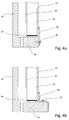
- FIGS. 4a and 4b show by way of example the attachment of a stand 16 to the base flange 26 of the tower section 10.
- the stand 16 is formed as a double-T-profile with two T-legs 30, 32.
- the tower wall facing T-leg 30 terminates above theticianflansches 26, so that the stand 16 is formed just above the researchingflansches 26 only as a T-profile with a T-leg 32.
- the lower end of the profile 16 is fixedly welded to a load distribution plate 35, wherein the load distribution plate 35 may extend laterally beyond the T-leg 32 also.
- a connecting flange 36 is connected to the T-leg 32, which protrudes downward over the stand 16.
- the connecting flange 36 is bolted to the foot flange 26 at the front end via a bolt 38 in order to connect the stand 16 to the base flange 26.
- Fig. 4b shows an alternative embodiment in which an angled connecting flange 40 is provided, which is fastened via a bolt 42 in the base flange 26.
- a bolt 42 in the base flange 26.
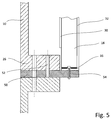
- Fig. 5 shows a further alternative embodiment of the tower installation according to the invention.
- the tower section 10 has a foot flange 26.
- the foot flange is connected to a load distribution plate 50 and thus formed according to the understanding of the invention as a multi-part foot flange.
- the stand 16 is formed as a double-T-profile with two T-legs 30, 32.
- the T-leg 30 pointing toward the tower wall ends above the base flange 26, so that the upright 16 in the region of the base flange 26 is formed merely as a T-profile with a T-leg 32.
- the lower end of the profile 16 is fixedly welded to a load distribution plate 35, which extends laterally beyond the T-leg 32 addition. In the region of the lateral extent, the load distribution plate 35 holes, which correspond to holes in the load distribution plate 50.
- the stand 16 is connected via the bores by means of bolts 54 with the load distribution plate as frequency
Landscapes
- Engineering & Computer Science (AREA)
- Chemical & Material Sciences (AREA)
- Life Sciences & Earth Sciences (AREA)
- Mechanical Engineering (AREA)
- Sustainable Energy (AREA)
- Combustion & Propulsion (AREA)
- Sustainable Development (AREA)
- General Engineering & Computer Science (AREA)
- Architecture (AREA)
- Materials Engineering (AREA)
- Wood Science & Technology (AREA)
- Civil Engineering (AREA)
- Structural Engineering (AREA)
- Wind Motors (AREA)
Claims (18)
- Tour pour une éolienne présentant une section de tour (10) avec une paroi de tour (15) et une bride inférieure (26) faisant saillie vers l'intérieur, dans laquelle une structure autoportante (14) encastrée dans la tour présentant au moins trois supports (16, 34) parallèles et écartés de la paroi de tour (15) et des traverses (18) reliant les supports l'un avec l'autre est prévue pour la section de tour (10),
caractérisée en ce que
les supports (16, 34) sont répartis sur la circonférence de la bride inférieure (26) et respectivement appuyés sur la bride inférieure (26). - Tour selon la revendication 1, caractérisée en ce que les extrémités des supports (16) détournées de la bride inférieure (26) sont libres et ne sont pas reliées à la paroi de tour (15).
- Tour selon la revendication 1 ou 2, caractérisée en ce que les traverses (18) sont reliées exclusivement aux supports (16).
- Tour selon l'une quelconque des revendications 1 à 3, caractérisée en ce que les traverses (18) sont disposées horizontalement entre les supports (16, 34) afin de former dans la structure encastrée dans la tour au moins une plate-forme (20, 22, 24).
- Tour selon la revendication 4, caractérisée en ce qu'une plate-forme (20) disposée au-dessus de la bride inférieure (26) présente des courts supports (34) qui étaient au moins une des traverses dans la plate-forme (20) sur la bride inférieure (26).
- Tour selon l'une quelconque des revendications 1 à 5, caractérisée en ce qu'au moins un élément d'amortissement (44) est disposé latéralement entre la structure encastrée dans la tour (14) et la face intérieure de la paroi de tour.
- Tour selon la revendication 6, caractérisée en ce que l'élément d'amortissement (44) est fixé sur la structure encastrée dans la tour.
- Tour selon l'une quelconque des revendications 1 à 7, caractérisée en ce que les supports (16, 34) sont formés comme profilé en T ou comme profilé en double T.
- Tour selon l'une quelconque des revendications 1 à 8, caractérisée en ce que chaque support (16, 34) présente à son extrémité orientée vers la bride inférieure (26) une tôle de répartition des charges (35).
- Tour selon la revendication 9, caractérisée en ce que la tôle de répartition des charges (35) présente des alésages pour le vissage sur la bride inférieure.
- Tour selon l'une quelconque des revendications 1 à 10, caractérisée en ce qu'est prévue sur au moins un support (16, 34), au niveau de son extrémité inférieure, une bride de connexion (36, 40) via laquelle le support (16, 34) est relié à la bride inférieure.
- Tour selon l'une quelconque des revendications 1 à 11, caractérisée en ce que la bride inférieure est formée en une pièce avec la paroi de tour.
- Tour selon l'une quelconque des revendications 1 à 11, caractérisée en ce que la bride inférieure est reliée à la section de tour à l'aide de moyens de fixation.
- Procédé de montage d'une tour pour une éolienne avec les étapes de procédé suivantes :- mise à disposition d'une section de tour (10) présentant sur une extrémité une bride inférieure (26) faisant saillie vers l'intérieur,- disposition des au moins trois supports répartis sur la circonférence de la bride inférieure,- fixation de chaque support à son extrémité inférieure sur la bride inférieure de manière à ce que la structure encastrée dans la tour autoportante soit étayée librement dans la section de tour sur la bride inférieure,- liaison des supports par des traverses,- montage de plaques de fond sur les traverses pour la formation de plateformes,- montage de composantes dans la structure encastrée dans la tour,- édification de la tour pour l'éolienne avec la section de tour dans laquelle les composantes sont déjà montées dans la structure encastrée dans la tour.
- Procédé selon la revendication 14, caractérisé en ce que, après le montage des composantes dans la structure encastrée dans la tour et avant édification de la tour, les composantes montées sont contrôlées.
- Procédé selon la revendication 14 ou 15, caractérisé en ce que la section de tour est fournie à la verticale.
- Procédé selon l'une quelconque des revendications 14 à 16, caractérisé en ce que la section de tour est transportée à la verticale au lieu d'édification de la tour.
- Procédé selon l'une quelconque des revendications 14 à 17, caractérisé par- la fixation d'une bride inférieure à la section de tour avant que la section de tour soit fournie.
Priority Applications (4)
| Application Number | Priority Date | Filing Date | Title |
|---|---|---|---|
| DK12002718.0T DK2653715T3 (da) | 2012-04-19 | 2012-04-19 | Tårn til et vindenergianlæg samt fremgangsmåde til rejsning heraf |
| EP12002718.0A EP2653715B1 (fr) | 2012-04-19 | 2012-04-19 | Tour pour une éolienne ainsi que le procédé de montage de cette tour |
| PT120027180T PT2653715T (pt) | 2012-04-19 | 2012-04-19 | Torre para um aerogerador e metódo para edificação da mesma |
| ES12002718.0T ES2578272T3 (es) | 2012-04-19 | 2012-04-19 | Torre para una instalación de energía eólica, así como procedimiento para la erección de la misma |
Applications Claiming Priority (1)
| Application Number | Priority Date | Filing Date | Title |
|---|---|---|---|
| EP12002718.0A EP2653715B1 (fr) | 2012-04-19 | 2012-04-19 | Tour pour une éolienne ainsi que le procédé de montage de cette tour |
Publications (2)
| Publication Number | Publication Date |
|---|---|
| EP2653715A1 EP2653715A1 (fr) | 2013-10-23 |
| EP2653715B1 true EP2653715B1 (fr) | 2016-04-13 |
Family
ID=46045650
Family Applications (1)
| Application Number | Title | Priority Date | Filing Date |
|---|---|---|---|
| EP12002718.0A Revoked EP2653715B1 (fr) | 2012-04-19 | 2012-04-19 | Tour pour une éolienne ainsi que le procédé de montage de cette tour |
Country Status (4)
| Country | Link |
|---|---|
| EP (1) | EP2653715B1 (fr) |
| DK (1) | DK2653715T3 (fr) |
| ES (1) | ES2578272T3 (fr) |
| PT (1) | PT2653715T (fr) |
Families Citing this family (3)
| Publication number | Priority date | Publication date | Assignee | Title |
|---|---|---|---|---|
| DK3312416T3 (da) * | 2016-10-24 | 2022-07-25 | Nordex Energy Spain S A | Vindmølletårn på fundament |
| WO2018157849A1 (fr) * | 2017-03-03 | 2018-09-07 | 青岛中天斯壮科技有限公司 | Structure de liaison pour armature de tube d'acier et corps de tour d'une tour de génération d'énergie éolienne en treillis, tour éolienne polygonale précontrainte munie d'une poutre de caisson circulaire pour ventilateur direct au sommet d'une tour, tour de génération d'énergie éolienne et tour éolienne ayant une structure anti-fatigue précontrainte |
| DE102018122638A1 (de) | 2018-09-17 | 2020-03-19 | Wobben Properties Gmbh | Windenergieanlagen-Turmsegment für einen Windenergieanlagen-Turm und Verfahren |
Citations (8)
| Publication number | Priority date | Publication date | Assignee | Title |
|---|---|---|---|---|
| US7504742B2 (en) | 2003-02-01 | 2009-03-17 | Aloys Wobben | Method for the erection of a wind energy plant, and wind energy plant |
| US20090126309A1 (en) | 2007-11-15 | 2009-05-21 | Thomas Edward Lyness | Methods and systems for assembling a tower |
| US20090223139A1 (en) | 2008-03-05 | 2009-09-10 | Karl-Heinz Meiners | Method and system for assembling components in a tower of a wind energy turbine |
| WO2010103114A1 (fr) | 2009-03-13 | 2010-09-16 | Xemc Darwind B.V. | Procédé de construction d'une éolienne et section inférieure de tour d'éolienne |
| US7805893B2 (en) | 2008-02-21 | 2010-10-05 | General Electric Company | Preassembled tower section of a wind power plant |
| EP2280168A2 (fr) | 2009-07-29 | 2011-02-02 | General Electric Company | Tour avec un système de guidage pour des modules de puissance électrique |
| EP2385250A2 (fr) | 2008-11-17 | 2011-11-09 | Vestas Wind Systems A/S | Tour d'éolienne et procédé d'agencement d'une plate-forme à l'intérieur de la tour |
| EP2431609A2 (fr) * | 2010-09-21 | 2012-03-21 | Fuji Jukogyo Kabushiki Kaisha | Éolienne à axe horizontal |
Family Cites Families (7)
| Publication number | Priority date | Publication date | Assignee | Title |
|---|---|---|---|---|
| US6782667B2 (en) * | 2000-12-05 | 2004-08-31 | Z-Tek, Llc | Tilt-up and telescopic support tower for large structures |
| DK200200178A (da) * | 2002-02-06 | 2003-08-07 | Vestas Wind Sys As | Ophængningsmidler til vindturbinetårne |
| CA2591536A1 (fr) | 2004-11-23 | 2006-06-01 | Vestas Wind Systems A/S | Eolienne, procede d'assemblage et de manipulation de l'eolienne et utilisations associees |
| ES2283192B1 (es) | 2005-09-16 | 2008-09-16 | GAMESA INNOVATION & TECHNOLOGY, S.L. | Metodo de montaje de elementos en el interior de la torre de un aerogenerador. |
| DE102005049289A1 (de) | 2005-10-14 | 2007-04-26 | Zarges Aluminium Systeme Gmbh | Kabelstütze |
| EP2038550B2 (fr) | 2006-06-29 | 2022-09-14 | Vestas Wind Systems A/S | Construction de tour pour une turbine éolienne |
| DE202010007565U1 (de) | 2010-06-04 | 2010-09-02 | Zarges Aluminium Systeme Gmbh | Turm, insbesondere Windkraftanlagenturm |
-
2012
- 2012-04-19 EP EP12002718.0A patent/EP2653715B1/fr not_active Revoked
- 2012-04-19 PT PT120027180T patent/PT2653715T/pt unknown
- 2012-04-19 ES ES12002718.0T patent/ES2578272T3/es active Active
- 2012-04-19 DK DK12002718.0T patent/DK2653715T3/da active
Patent Citations (8)
| Publication number | Priority date | Publication date | Assignee | Title |
|---|---|---|---|---|
| US7504742B2 (en) | 2003-02-01 | 2009-03-17 | Aloys Wobben | Method for the erection of a wind energy plant, and wind energy plant |
| US20090126309A1 (en) | 2007-11-15 | 2009-05-21 | Thomas Edward Lyness | Methods and systems for assembling a tower |
| US7805893B2 (en) | 2008-02-21 | 2010-10-05 | General Electric Company | Preassembled tower section of a wind power plant |
| US20090223139A1 (en) | 2008-03-05 | 2009-09-10 | Karl-Heinz Meiners | Method and system for assembling components in a tower of a wind energy turbine |
| EP2385250A2 (fr) | 2008-11-17 | 2011-11-09 | Vestas Wind Systems A/S | Tour d'éolienne et procédé d'agencement d'une plate-forme à l'intérieur de la tour |
| WO2010103114A1 (fr) | 2009-03-13 | 2010-09-16 | Xemc Darwind B.V. | Procédé de construction d'une éolienne et section inférieure de tour d'éolienne |
| EP2280168A2 (fr) | 2009-07-29 | 2011-02-02 | General Electric Company | Tour avec un système de guidage pour des modules de puissance électrique |
| EP2431609A2 (fr) * | 2010-09-21 | 2012-03-21 | Fuji Jukogyo Kabushiki Kaisha | Éolienne à axe horizontal |
Non-Patent Citations (2)
| Title |
|---|
| "Wikipedia, der freien Enzyklopädie", FLANSCH, 17 March 2012 (2012-03-17), pages 1, XP055343025, Retrieved from the Internet <URL:https://de.wikipedia.org/wiki/Flansch> |
| CHRISTIAN PETERSEN: "Stahlbau. Grundlagen der Berechnung und baulichen Ausbildungvon Stahlbauten, 3. Aufl.", 1993, VIEWEG, pages: 533 - 534, 577-581, 992-993, XP055343030 |
Also Published As
| Publication number | Publication date |
|---|---|
| DK2653715T3 (da) | 2016-08-01 |
| EP2653715A1 (fr) | 2013-10-23 |
| PT2653715T (pt) | 2016-07-19 |
| ES2578272T3 (es) | 2016-07-22 |
Similar Documents
| Publication | Publication Date | Title |
|---|---|---|
| EP2574711B2 (fr) | Tour pour une éolienne | |
| EP3042011B1 (fr) | Procédé de montage d'équipements d'une tour | |
| EP3488060B1 (fr) | Procédé pour ériger une tour pour une éolienne | |
| EP2909476A1 (fr) | Structure de service destinée à une tour, tour dotée d'une structure de service et procédé de construction d'une structure de service à l'intérieur d'une tour | |
| EP0960986A2 (fr) | Procédé et dispositif pour la construction de structures élancées et creuses du type tour de deux cent mètres et plus de haut, spécialement tour pour aérogénérateurs | |
| DE102010048547A1 (de) | Turm, insbesondere für eine Windkraftanlage und Verfahren zur Herstellung eines Turmes | |
| EP3252304A1 (fr) | Dispositif et système de prémontage horizontal d'un rotor d'éolienne | |
| AT506625A4 (de) | Instandhaltungsplattform | |
| EP2692967A2 (fr) | Procédé pour ériger un mât en acier d'une éolienne et mât en acier pour une éolienne | |
| DE202009015885U1 (de) | Solarer Carport | |
| WO1998009072A9 (fr) | Pylones pour eolienne | |
| WO1998009072A1 (fr) | Pylones pour eolienne | |
| EP2653715A1 (fr) | Tour pour une éolienne ainsi que le procédé de montage de cette tour | |
| DE102012008120A1 (de) | Verfahren zum Errichten eines Turmeinbaus in einem Windenergieanlagenturm | |
| WO2015039777A1 (fr) | Toit de protection variable | |
| EP3445971A1 (fr) | Corps de raccordement pour pylône d'éolienne, pylône comprenant ce corps de raccordement ainsi que son procédé de construction | |
| DE202011106727U1 (de) | Versorgungsgerüst für einen Turm | |
| DE202011001695U1 (de) | Stahlturm für Windkraftanlagen | |
| EP3597829B1 (fr) | Renfort de fondations pour ouvrages en mer | |
| EP2725223B1 (fr) | Groupe d'installations éoliennes | |
| EP2211122A1 (fr) | Kit de montage destiné à soutenir des modules solaires | |
| DE102016102213A1 (de) | Verfahren zum Errichten eines Windkraftturms einer Windkraftanlage mittels eines Krans, Windkraftturm sowie Stahlsegment für einen Windkraftturm einer Windkraftanlage | |
| DE10308239A1 (de) | Verfahren und Vorrichtung zur Errichtung einer Windenergieanlage | |
| DE102010012408A1 (de) | Trägeranordnung für eine Windenergieanlage, Windenergieanlage mit einer Trägeranordnung und Verfahren zum Errichten einer Windenergieanlage | |
| EP3252305B1 (fr) | Dispositif pour l'installation d'une éolienne et utilisation dudit dispositif |
Legal Events
| Date | Code | Title | Description |
|---|---|---|---|
| PUAI | Public reference made under article 153(3) epc to a published international application that has entered the european phase |
Free format text: ORIGINAL CODE: 0009012 |
|
| AK | Designated contracting states |
Kind code of ref document: A1 Designated state(s): AL AT BE BG CH CY CZ DE DK EE ES FI FR GB GR HR HU IE IS IT LI LT LU LV MC MK MT NL NO PL PT RO RS SE SI SK SM TR |
|
| AX | Request for extension of the european patent |
Extension state: BA ME |
|
| 17P | Request for examination filed |
Effective date: 20140416 |
|
| RBV | Designated contracting states (corrected) |
Designated state(s): AL AT BE BG CH CY CZ DE DK EE ES FI FR GB GR HR HU IE IS IT LI LT LU LV MC MK MT NL NO PL PT RO RS SE SI SK SM TR |
|
| GRAP | Despatch of communication of intention to grant a patent |
Free format text: ORIGINAL CODE: EPIDOSNIGR1 |
|
| INTG | Intention to grant announced |
Effective date: 20150505 |
|
| RIN1 | Information on inventor provided before grant (corrected) |
Inventor name: BOROWSKI, STEFFEN Inventor name: HAENLER, MICHAEL |
|
| GRAP | Despatch of communication of intention to grant a patent |
Free format text: ORIGINAL CODE: EPIDOSNIGR1 |
|
| INTG | Intention to grant announced |
Effective date: 20151116 |
|
| GRAS | Grant fee paid |
Free format text: ORIGINAL CODE: EPIDOSNIGR3 |
|
| GRAA | (expected) grant |
Free format text: ORIGINAL CODE: 0009210 |
|
| RIC1 | Information provided on ipc code assigned before grant |
Ipc: F03D 80/00 20160101ALI20160225BHEP Ipc: F03D 1/00 20060101AFI20160225BHEP Ipc: E04H 12/08 20060101ALI20160225BHEP |
|
| AK | Designated contracting states |
Kind code of ref document: B1 Designated state(s): AL AT BE BG CH CY CZ DE DK EE ES FI FR GB GR HR HU IE IS IT LI LT LU LV MC MK MT NL NO PL PT RO RS SE SI SK SM TR |
|
| REG | Reference to a national code |
Ref country code: GB Ref legal event code: FG4D Free format text: NOT ENGLISH |
|
| REG | Reference to a national code |
Ref country code: AT Ref legal event code: REF Ref document number: 790443 Country of ref document: AT Kind code of ref document: T Effective date: 20160415 Ref country code: CH Ref legal event code: EP |
|
| REG | Reference to a national code |
Ref country code: IE Ref legal event code: FG4D Free format text: LANGUAGE OF EP DOCUMENT: GERMAN |
|
| REG | Reference to a national code |
Ref country code: DE Ref legal event code: R096 Ref document number: 502012006674 Country of ref document: DE |
|
| REG | Reference to a national code |
Ref country code: FR Ref legal event code: PLFP Year of fee payment: 5 |
|
| REG | Reference to a national code |
Ref country code: PT Ref legal event code: SC4A Ref document number: 2653715 Country of ref document: PT Date of ref document: 20160719 Kind code of ref document: T Free format text: AVAILABILITY OF NATIONAL TRANSLATION Effective date: 20160713 |
|
| REG | Reference to a national code |
Ref country code: ES Ref legal event code: FG2A Ref document number: 2578272 Country of ref document: ES Kind code of ref document: T3 Effective date: 20160722 |
|
| REG | Reference to a national code |
Ref country code: DK Ref legal event code: T3 Effective date: 20160721 |
|
| REG | Reference to a national code |
Ref country code: LT Ref legal event code: MG4D |
|
| PG25 | Lapsed in a contracting state [announced via postgrant information from national office to epo] |
Ref country code: BE Free format text: LAPSE BECAUSE OF NON-PAYMENT OF DUE FEES Effective date: 20160430 |
|
| REG | Reference to a national code |
Ref country code: NL Ref legal event code: MP Effective date: 20160413 |
|
| PG25 | Lapsed in a contracting state [announced via postgrant information from national office to epo] |
Ref country code: LT Free format text: LAPSE BECAUSE OF FAILURE TO SUBMIT A TRANSLATION OF THE DESCRIPTION OR TO PAY THE FEE WITHIN THE PRESCRIBED TIME-LIMIT Effective date: 20160413 Ref country code: FI Free format text: LAPSE BECAUSE OF FAILURE TO SUBMIT A TRANSLATION OF THE DESCRIPTION OR TO PAY THE FEE WITHIN THE PRESCRIBED TIME-LIMIT Effective date: 20160413 Ref country code: NO Free format text: LAPSE BECAUSE OF FAILURE TO SUBMIT A TRANSLATION OF THE DESCRIPTION OR TO PAY THE FEE WITHIN THE PRESCRIBED TIME-LIMIT Effective date: 20160713 Ref country code: NL Free format text: LAPSE BECAUSE OF FAILURE TO SUBMIT A TRANSLATION OF THE DESCRIPTION OR TO PAY THE FEE WITHIN THE PRESCRIBED TIME-LIMIT Effective date: 20160413 Ref country code: PL Free format text: LAPSE BECAUSE OF FAILURE TO SUBMIT A TRANSLATION OF THE DESCRIPTION OR TO PAY THE FEE WITHIN THE PRESCRIBED TIME-LIMIT Effective date: 20160413 |
|
| PG25 | Lapsed in a contracting state [announced via postgrant information from national office to epo] |
Ref country code: HR Free format text: LAPSE BECAUSE OF FAILURE TO SUBMIT A TRANSLATION OF THE DESCRIPTION OR TO PAY THE FEE WITHIN THE PRESCRIBED TIME-LIMIT Effective date: 20160413 Ref country code: LV Free format text: LAPSE BECAUSE OF FAILURE TO SUBMIT A TRANSLATION OF THE DESCRIPTION OR TO PAY THE FEE WITHIN THE PRESCRIBED TIME-LIMIT Effective date: 20160413 Ref country code: RS Free format text: LAPSE BECAUSE OF FAILURE TO SUBMIT A TRANSLATION OF THE DESCRIPTION OR TO PAY THE FEE WITHIN THE PRESCRIBED TIME-LIMIT Effective date: 20160413 Ref country code: SE Free format text: LAPSE BECAUSE OF FAILURE TO SUBMIT A TRANSLATION OF THE DESCRIPTION OR TO PAY THE FEE WITHIN THE PRESCRIBED TIME-LIMIT Effective date: 20160413 Ref country code: GR Free format text: LAPSE BECAUSE OF FAILURE TO SUBMIT A TRANSLATION OF THE DESCRIPTION OR TO PAY THE FEE WITHIN THE PRESCRIBED TIME-LIMIT Effective date: 20160714 |
|
| REG | Reference to a national code |
Ref country code: CH Ref legal event code: PL |
|
| PG25 | Lapsed in a contracting state [announced via postgrant information from national office to epo] |
Ref country code: IT Free format text: LAPSE BECAUSE OF FAILURE TO SUBMIT A TRANSLATION OF THE DESCRIPTION OR TO PAY THE FEE WITHIN THE PRESCRIBED TIME-LIMIT Effective date: 20160413 |
|
| REG | Reference to a national code |
Ref country code: DE Ref legal event code: R026 Ref document number: 502012006674 Country of ref document: DE |
|
| PLBI | Opposition filed |
Free format text: ORIGINAL CODE: 0009260 |
|
| REG | Reference to a national code |
Ref country code: IE Ref legal event code: MM4A |
|
| PG25 | Lapsed in a contracting state [announced via postgrant information from national office to epo] |
Ref country code: RO Free format text: LAPSE BECAUSE OF FAILURE TO SUBMIT A TRANSLATION OF THE DESCRIPTION OR TO PAY THE FEE WITHIN THE PRESCRIBED TIME-LIMIT Effective date: 20160413 Ref country code: EE Free format text: LAPSE BECAUSE OF FAILURE TO SUBMIT A TRANSLATION OF THE DESCRIPTION OR TO PAY THE FEE WITHIN THE PRESCRIBED TIME-LIMIT Effective date: 20160413 Ref country code: MC Free format text: LAPSE BECAUSE OF FAILURE TO SUBMIT A TRANSLATION OF THE DESCRIPTION OR TO PAY THE FEE WITHIN THE PRESCRIBED TIME-LIMIT Effective date: 20160413 Ref country code: CH Free format text: LAPSE BECAUSE OF NON-PAYMENT OF DUE FEES Effective date: 20160430 Ref country code: SK Free format text: LAPSE BECAUSE OF FAILURE TO SUBMIT A TRANSLATION OF THE DESCRIPTION OR TO PAY THE FEE WITHIN THE PRESCRIBED TIME-LIMIT Effective date: 20160413 Ref country code: LI Free format text: LAPSE BECAUSE OF NON-PAYMENT OF DUE FEES Effective date: 20160430 Ref country code: CZ Free format text: LAPSE BECAUSE OF FAILURE TO SUBMIT A TRANSLATION OF THE DESCRIPTION OR TO PAY THE FEE WITHIN THE PRESCRIBED TIME-LIMIT Effective date: 20160413 |
|
| PLAX | Notice of opposition and request to file observation + time limit sent |
Free format text: ORIGINAL CODE: EPIDOSNOBS2 |
|
| 26 | Opposition filed |
Opponent name: GE WIND ENERGY GMBH Effective date: 20170113 |
|
| PG25 | Lapsed in a contracting state [announced via postgrant information from national office to epo] |
Ref country code: SM Free format text: LAPSE BECAUSE OF FAILURE TO SUBMIT A TRANSLATION OF THE DESCRIPTION OR TO PAY THE FEE WITHIN THE PRESCRIBED TIME-LIMIT Effective date: 20160413 |
|
| GBPC | Gb: european patent ceased through non-payment of renewal fee |
Effective date: 20160713 |
|
| REG | Reference to a national code |
Ref country code: FR Ref legal event code: PLFP Year of fee payment: 6 |
|
| PG25 | Lapsed in a contracting state [announced via postgrant information from national office to epo] |
Ref country code: SI Free format text: LAPSE BECAUSE OF FAILURE TO SUBMIT A TRANSLATION OF THE DESCRIPTION OR TO PAY THE FEE WITHIN THE PRESCRIBED TIME-LIMIT Effective date: 20160413 Ref country code: IE Free format text: LAPSE BECAUSE OF NON-PAYMENT OF DUE FEES Effective date: 20160419 Ref country code: GB Free format text: LAPSE BECAUSE OF NON-PAYMENT OF DUE FEES Effective date: 20160713 |
|
| PLBB | Reply of patent proprietor to notice(s) of opposition received |
Free format text: ORIGINAL CODE: EPIDOSNOBS3 |
|
| REG | Reference to a national code |
Ref country code: FR Ref legal event code: PLFP Year of fee payment: 7 |
|
| PG25 | Lapsed in a contracting state [announced via postgrant information from national office to epo] |
Ref country code: HU Free format text: LAPSE BECAUSE OF FAILURE TO SUBMIT A TRANSLATION OF THE DESCRIPTION OR TO PAY THE FEE WITHIN THE PRESCRIBED TIME-LIMIT; INVALID AB INITIO Effective date: 20120419 Ref country code: CY Free format text: LAPSE BECAUSE OF FAILURE TO SUBMIT A TRANSLATION OF THE DESCRIPTION OR TO PAY THE FEE WITHIN THE PRESCRIBED TIME-LIMIT Effective date: 20160413 |
|
| REG | Reference to a national code |
Ref country code: AT Ref legal event code: MM01 Ref document number: 790443 Country of ref document: AT Kind code of ref document: T Effective date: 20170419 |
|
| PG25 | Lapsed in a contracting state [announced via postgrant information from national office to epo] |
Ref country code: IS Free format text: LAPSE BECAUSE OF FAILURE TO SUBMIT A TRANSLATION OF THE DESCRIPTION OR TO PAY THE FEE WITHIN THE PRESCRIBED TIME-LIMIT Effective date: 20160413 Ref country code: MK Free format text: LAPSE BECAUSE OF FAILURE TO SUBMIT A TRANSLATION OF THE DESCRIPTION OR TO PAY THE FEE WITHIN THE PRESCRIBED TIME-LIMIT Effective date: 20160413 Ref country code: TR Free format text: LAPSE BECAUSE OF FAILURE TO SUBMIT A TRANSLATION OF THE DESCRIPTION OR TO PAY THE FEE WITHIN THE PRESCRIBED TIME-LIMIT Effective date: 20160413 Ref country code: LU Free format text: LAPSE BECAUSE OF NON-PAYMENT OF DUE FEES Effective date: 20160419 Ref country code: MT Free format text: LAPSE BECAUSE OF FAILURE TO SUBMIT A TRANSLATION OF THE DESCRIPTION OR TO PAY THE FEE WITHIN THE PRESCRIBED TIME-LIMIT Effective date: 20160413 |
|
| PG25 | Lapsed in a contracting state [announced via postgrant information from national office to epo] |
Ref country code: BG Free format text: LAPSE BECAUSE OF FAILURE TO SUBMIT A TRANSLATION OF THE DESCRIPTION OR TO PAY THE FEE WITHIN THE PRESCRIBED TIME-LIMIT Effective date: 20160413 |
|
| PGFP | Annual fee paid to national office [announced via postgrant information from national office to epo] |
Ref country code: DK Payment date: 20180424 Year of fee payment: 7 Ref country code: PT Payment date: 20180411 Year of fee payment: 7 Ref country code: ES Payment date: 20180523 Year of fee payment: 7 Ref country code: DE Payment date: 20180608 Year of fee payment: 7 |
|
| PG25 | Lapsed in a contracting state [announced via postgrant information from national office to epo] |
Ref country code: AT Free format text: LAPSE BECAUSE OF NON-PAYMENT OF DUE FEES Effective date: 20170419 |
|
| PGFP | Annual fee paid to national office [announced via postgrant information from national office to epo] |
Ref country code: FR Payment date: 20180424 Year of fee payment: 7 |
|
| REG | Reference to a national code |
Ref country code: DE Ref legal event code: R064 Ref document number: 502012006674 Country of ref document: DE Ref country code: DE Ref legal event code: R103 Ref document number: 502012006674 Country of ref document: DE |
|
| PG25 | Lapsed in a contracting state [announced via postgrant information from national office to epo] |
Ref country code: AL Free format text: LAPSE BECAUSE OF FAILURE TO SUBMIT A TRANSLATION OF THE DESCRIPTION OR TO PAY THE FEE WITHIN THE PRESCRIBED TIME-LIMIT Effective date: 20160413 |
|
| RDAF | Communication despatched that patent is revoked |
Free format text: ORIGINAL CODE: EPIDOSNREV1 |
|
| STAA | Information on the status of an ep patent application or granted ep patent |
Free format text: STATUS: THE PATENT HAS BEEN GRANTED |
|
| RDAG | Patent revoked |
Free format text: ORIGINAL CODE: 0009271 |
|
| STAA | Information on the status of an ep patent application or granted ep patent |
Free format text: STATUS: PATENT REVOKED |
|
| 27W | Patent revoked |
Effective date: 20181002 |
|
| REG | Reference to a national code |
Ref country code: BE Ref legal event code: MM Effective date: 20160430 |
|
| REG | Reference to a national code |
Ref country code: AT Ref legal event code: MA03 Ref document number: 790443 Country of ref document: AT Kind code of ref document: T Effective date: 20181002 |