EP3252305B1 - Dispositif pour l'installation d'une éolienne et utilisation dudit dispositif - Google Patents
Dispositif pour l'installation d'une éolienne et utilisation dudit dispositif Download PDFInfo
- Publication number
- EP3252305B1 EP3252305B1 EP17174028.5A EP17174028A EP3252305B1 EP 3252305 B1 EP3252305 B1 EP 3252305B1 EP 17174028 A EP17174028 A EP 17174028A EP 3252305 B1 EP3252305 B1 EP 3252305B1
- Authority
- EP
- European Patent Office
- Prior art keywords
- tower
- nacelle
- tower segment
- wind turbine
- mounting
- Prior art date
- Legal status (The legal status is an assumption and is not a legal conclusion. Google has not performed a legal analysis and makes no representation as to the accuracy of the status listed.)
- Active
Links
- 238000012360 testing method Methods 0.000 claims description 5
- 230000004888 barrier function Effects 0.000 claims description 3
- 238000009434 installation Methods 0.000 description 22
- 238000010276 construction Methods 0.000 description 8
- 230000008901 benefit Effects 0.000 description 3
- 230000007547 defect Effects 0.000 description 3
- 238000000034 method Methods 0.000 description 3
- 230000001934 delay Effects 0.000 description 2
- 230000001419 dependent effect Effects 0.000 description 2
- 230000008439 repair process Effects 0.000 description 2
- 230000000712 assembly Effects 0.000 description 1
- 238000000429 assembly Methods 0.000 description 1
- 238000001514 detection method Methods 0.000 description 1
- 238000011161 development Methods 0.000 description 1
- 230000018109 developmental process Effects 0.000 description 1
- 238000004519 manufacturing process Methods 0.000 description 1
- 238000001556 precipitation Methods 0.000 description 1
- 230000007704 transition Effects 0.000 description 1
- 238000012795 verification Methods 0.000 description 1
Images


Classifications
-
- F—MECHANICAL ENGINEERING; LIGHTING; HEATING; WEAPONS; BLASTING
- F03—MACHINES OR ENGINES FOR LIQUIDS; WIND, SPRING, OR WEIGHT MOTORS; PRODUCING MECHANICAL POWER OR A REACTIVE PROPULSIVE THRUST, NOT OTHERWISE PROVIDED FOR
- F03D—WIND MOTORS
- F03D13/00—Assembly, mounting or commissioning of wind motors; Arrangements specially adapted for transporting wind motor components
- F03D13/10—Assembly of wind motors; Arrangements for erecting wind motors
-
- F—MECHANICAL ENGINEERING; LIGHTING; HEATING; WEAPONS; BLASTING
- F05—INDEXING SCHEMES RELATING TO ENGINES OR PUMPS IN VARIOUS SUBCLASSES OF CLASSES F01-F04
- F05B—INDEXING SCHEME RELATING TO WIND, SPRING, WEIGHT, INERTIA OR LIKE MOTORS, TO MACHINES OR ENGINES FOR LIQUIDS COVERED BY SUBCLASSES F03B, F03D AND F03G
- F05B2230/00—Manufacture
- F05B2230/60—Assembly methods
- F05B2230/61—Assembly methods using auxiliary equipment for lifting or holding
-
- F—MECHANICAL ENGINEERING; LIGHTING; HEATING; WEAPONS; BLASTING
- F05—INDEXING SCHEMES RELATING TO ENGINES OR PUMPS IN VARIOUS SUBCLASSES OF CLASSES F01-F04
- F05B—INDEXING SCHEME RELATING TO WIND, SPRING, WEIGHT, INERTIA OR LIKE MOTORS, TO MACHINES OR ENGINES FOR LIQUIDS COVERED BY SUBCLASSES F03B, F03D AND F03G
- F05B2260/00—Function
- F05B2260/02—Transport, e.g. specific adaptations or devices for conveyance
-
- F—MECHANICAL ENGINEERING; LIGHTING; HEATING; WEAPONS; BLASTING
- F05—INDEXING SCHEMES RELATING TO ENGINES OR PUMPS IN VARIOUS SUBCLASSES OF CLASSES F01-F04
- F05B—INDEXING SCHEME RELATING TO WIND, SPRING, WEIGHT, INERTIA OR LIKE MOTORS, TO MACHINES OR ENGINES FOR LIQUIDS COVERED BY SUBCLASSES F03B, F03D AND F03G
- F05B2260/00—Function
- F05B2260/83—Testing, e.g. methods, components or tools therefor
-
- Y—GENERAL TAGGING OF NEW TECHNOLOGICAL DEVELOPMENTS; GENERAL TAGGING OF CROSS-SECTIONAL TECHNOLOGIES SPANNING OVER SEVERAL SECTIONS OF THE IPC; TECHNICAL SUBJECTS COVERED BY FORMER USPC CROSS-REFERENCE ART COLLECTIONS [XRACs] AND DIGESTS
- Y02—TECHNOLOGIES OR APPLICATIONS FOR MITIGATION OR ADAPTATION AGAINST CLIMATE CHANGE
- Y02E—REDUCTION OF GREENHOUSE GAS [GHG] EMISSIONS, RELATED TO ENERGY GENERATION, TRANSMISSION OR DISTRIBUTION
- Y02E10/00—Energy generation through renewable energy sources
- Y02E10/70—Wind energy
- Y02E10/72—Wind turbines with rotation axis in wind direction
-
- Y—GENERAL TAGGING OF NEW TECHNOLOGICAL DEVELOPMENTS; GENERAL TAGGING OF CROSS-SECTIONAL TECHNOLOGIES SPANNING OVER SEVERAL SECTIONS OF THE IPC; TECHNICAL SUBJECTS COVERED BY FORMER USPC CROSS-REFERENCE ART COLLECTIONS [XRACs] AND DIGESTS
- Y02—TECHNOLOGIES OR APPLICATIONS FOR MITIGATION OR ADAPTATION AGAINST CLIMATE CHANGE
- Y02P—CLIMATE CHANGE MITIGATION TECHNOLOGIES IN THE PRODUCTION OR PROCESSING OF GOODS
- Y02P70/00—Climate change mitigation technologies in the production process for final industrial or consumer products
- Y02P70/50—Manufacturing or production processes characterised by the final manufactured product
Definitions
- the invention relates to a device for erecting a wind turbine and its uses.
- a wind turbine comprises a tower constructed on a foundation of several tower sections, at the upper end of which a gondola is rotatably arranged in the azimuth direction.
- a rotor drivable by the rotor is arranged with a substantially horizontal axis of rotation, which drives a generator arranged in the nacelle.
- the electrical power generated in this way can, if appropriate with the interposition of converters and / or transformers, be fed into a supply network.
- the tower is first constructed according to the prior art after creation of the foundation by gradually lifted the individual tower sections on the foundation or already mounted tower sections and fixed there.
- the tower is completed, either the nacelle is completely or a first part of the nacelle lifted onto the tower and rotatably mounted at the top for later azimuth orientation.
- the driveline is in the already mounted part of the nacelle lifted and aligned there and fixed. Only then is the gondola closed with a roof.
- the assembly of the rotor takes place.
- Two fundamentally different assembly methods are known. In one assembly method, the rotor hub is first rotatably attached to the nacelle, before subsequently the rotor blades are fastened individually to the already in position rotor hub. In the other assembly method, the rotor is preassembled on the ground, i. The rotor blades are already attached to the rotor hub, before the rotor is lifted as a whole to the height of the nacelle and fastened there.
- a disadvantage of this prior art is that virtually for the entire period of installation of a wind turbine, a main crane is needed whose hook height makes it possible to raise the components to be mounted on the tower top. Due to the size of the crane required, it can not be used elsewhere during assembly, when it is not mandatory, such as testing or commissioning individual components in the nacelle before the rotor is mounted. The same applies if the individual components are to be delivered to the place of installation in a timely manner to their respective assembly, but there are delays in the delivery.
- the invention has for its object to provide a comparison with the prior art improved device for building a wind turbine, as well as to use this device.
- the invention relates to a device for pre-assembly of the nacelle of a wind turbine on a top tower segment, wherein a receptacle for vertical attachment of a tower segment of the wind turbine is arranged on a base frame and wherein a base frame arranged receptacle for the rotor hub for the horizontal mounting of the wind turbine rotor is provided , which is arranged opposite the receptacle for the tower segment, that the installation of the wind turbine rotor is also possible with a tower segment arranged on the receptacle for the tower segment, wherein the tower segment arranged as a counterweight during assembly of the wind turbine rotor acts, the mounting device so folds - And / or telescoping is that it has outer dimensions of a maximum of 2.5 mx 2.75 mx 10 m in the folded state.
- the invention further relates to the use of a device according to the invention, wherein a top tower segment in a vertical position is arranged in the receptacle and wherein the nacelle is pre-assembled on the top tower segment, before the top tower segment is lifted onto the tower mounted on the top tower segment and fastened there.
- the nacelle By mounting the gondola already close to the ground on the topmost tower segment when constructing a wind energy plant according to the invention and then both components are lifted together on the tower which is already built up to a large extent from the remaining tower segments and fastened there, the nacelle can be preassembled top tower segment already carried out various installation and verification work near the ground, which would otherwise be carried out at high altitude.
- missing parts or defects on the nacelle can be detected at a time when the nacelle is still near the ground, so that the subsequent installation of missing parts or the repair of defects is often easier.
- the preassembly of the nacelle can be started so early before putting the nacelle together with the top tower segment that a time buffer for any delays in the pre-assembly of the nacelle is available and the schedule for the actual erection of the wind turbine with the placement of the nacelle is not endangered as one of the last steps.
- pre-assembly near the ground is less dependent on the weather than mounting the gondola at high altitudes.
- the pre-assembly can be made regardless of the construction of the tower of the other tower segments.
- no large crane is required for the actual pre-assembly.
- the topmost tower segment is essentially only to attach and connect the various lines and / or rail systems at the transition between the top tower segment and the underlying tower segment.
- Another (internal) expansion of the nacelle and the upper tower segment is usually no longer required. Rather, almost directly the rotor can be attached to the nacelle.
- the uppermost tower segment for the preassembly of the nacelle is in a vertical position.
- the topmost tower segment is thus in an orientation for the preassembly of the nacelle, in which it is also in the fully erected state of the wind turbine. Consequently, the nacelle is preassembled in a position in which it is also in the final state of the wind turbine.
- the preassembly of the nacelle on the uppermost tower segment includes the assembly of the driveline in the nacelle, the assembly and alignment of the generator shaft, the installation of barriers, the installation of driveline sensors, the installation of power cables in the nacelle, the installation of the cable loop in the nacelle area, the installation of the Azimutverstellantriebs and / or the installation of the nacelle lighting. All of the aforementioned assemblies can be easily carried out already during the pre-assembly of the nacelle on the top tower segment.
- the preassembly of the nacelle on the uppermost tower segment comprises the commissioning and / or testing of the nacelle control, the sensor system and / or the azimuth adjustment.
- the nacelle can be externally powered by the electrical power required for each test. If the gondola has an emergency generator, which is already mounted, but the required electrical power can also be provided by this.
- the uppermost tower segment preferably has a height of at least 10 m, more preferably at least 15 m.
- the pre-assembly is also connected to the nacelle components that protrude into the tower, such as. The cable loop, allows.
- the attachment of the uppermost tower segment to the partially assembled tower preferably includes the installation of tower bolts, ladder connectors and bus bar connectors.
- the rest of the (inner) expansion of the uppermost tower segment and / or the nacelle is, as already mentioned, preferably before the attachment of the uppermost tower segment on the partially assembled tower.
- the rotor After attachment of the uppermost tower segment on the partially assembled tower, the rotor is preferably rotatably attached to the nacelle of the wind turbine. Since in the inventive use of the device after the attachment of the The top tower segment on the partially assembled tower no or very few assembly work on the nacelle are required, the attachment of the rotor to the nacelle can be carried out immediately after or at a short time interval.
- the advantages of the invention are particularly apparent in the construction of several, preferably all wind turbines of a wind farm. Due to the proximity of the erected wind turbines of a wind farm, the cranes required for the construction of the tower and for the pre-assembly of the nacelle on the top tower segment - usually at least one large crane and a smaller crane - can be used very efficiently.
- the advantages arise in particular if five or more wind turbines, preferably eight or more wind turbines of a wind farm to be built at the same time.
- the mounting device comprises a receptacle arranged on the base frame for the rotor hub for the horizontal mounting of the wind turbine rotor, which is arranged opposite the receptacle for the tower segment that the installation of the wind turbine rotor is also possible in a tower segment arranged on the receptacle for the tower segment, wherein the thus arranged tower segment acts as a counterweight during assembly of the wind turbine rotor.
- the latter can be achieved by the two recordings are arranged in a horizontal direction spaced from each other.
- a tower segment arranged on the receptacle for a tower segment can protrude in particular between the rotor blades of a rotor which is completely mounted on the receptacle for the wind energy plant rotor, which immediately shows that the assembly of the wind turbine rotor also occurs Presence of a corresponding tower segment - even with possibly already mounted thereon gondola - is possible.
- the rotor hub with vertical orientation of the rotor hub axis is first attached to a suitable receptacle before the individual rotor blades are attached to it in succession. Since the rotor blades are mounted one after the other, the moments for the wind turbine rotor during assembly are affected by different moments resulting from the weight forces of the rotor blades, in particular before all the rotor blades are mounted. To compensate for these moments, it is known as a way to use counterweights.
- the receptacle for the tower segment on the base frame is arranged so that a tower segment arranged thereon - possibly with it already mounted gondola - serves as a counterweight. This offers the advantage that no separate counterweights need to be provided, which in particular reduces the overall transport costs for base frame ballast weights or the aids for setting up a wind energy plant.
- the receptacle for the rotor hub for the horizontal assembly of the wind turbine rotor comprises a rotating device with which the rotor hub fixed to the receptacle can be rotated about the rotor hub axis.
- a corresponding turning device makes it possible to rotate the partially assembled wind turbine rotor during assembly so that the moment acting on it by the mounting device can be compensated by the weight of a tower segment arranged on the receptacle for tower segments.
- the mounting device can be hinged and / or telescoped such that it has outer dimensions of not more than 2.5 m ⁇ 2.75 m ⁇ 10 m in the folded state, preferably that the outer dimensions are selected such that the mounting device is mounted in a 40-foot frame.
- Standard container more preferably loaded in a standard 20-foot container.
- the mounting device can be so merge to a transport volume, which allows easy transport without interference, especially on the road and / or by boat.
- the receptacle for the wind turbine rotor of the mounting device comprises at least one tower element of a tower system of a building crane, wherein the tower system is releasably secured to the base frame and the receptacle for the wind turbine rotor is arranged at the end remote from the base frame of the tower system.
- a suitable adapter device can be provided which can be connected on one side with the tower system and on the other side has a rotor flange for attachment of the rotor hub.
- Tower system of a building crane refers to the system for the construction of the tower of a mobile tower crane, in particular a top-rotating tower crane.
- Corresponding tower systems are offered by various manufacturers and include a base segment on which individual tower segments are arranged to ultimately form the tower of the crane at a desired height.
- the individual tower segments are designed and dimensioned so that they can be easily transported by truck to the desired location of the tower crane and include interfaces for connection to other segments.
- the transport of the mounting device according to the invention from one location to the next essentially limited to the base frame.
- the tower system can be provided locally, for example by local lenders of tower cranes with suitable tower systems. It can thus be avoided that a high transport volume and / or a high transport weight must be transported over some long distances.
- a tower system in mounting for the wind turbine rotor allows for mounting the rotor spaced from the ground.
- the tower system comprising at least one tower segment necessarily already has a certain height, mounted thereon a rotor of a wind turbine is spaced from the ground so that at least one passage through the rotor is regularly possible.
- the distance between the ground and the rotor can also be chosen so well that any desired clearance height, for example to ensure passage through vehicles or other equipment, is achieved. It can also be achieved to mount the rotor above so-called inventory obstacles, such as trees, so that they do not have to be removed, e.g. by precipitation.
- the mounting device allows the rotor mounting on a slope by the rotor is increased so that the directed to the slope leaves can be positioned horizontally.
- the tower element and / or the number of tower elements is preferably selected such that the minimum clearance height below a wind turbine rotor mounted on the receptacle is at least 4.5 m, preferably at least 8 m, more preferably at least 9.5 m.
- a plurality of tower elements arranged on top of each other can be provided in order to achieve the ultimately desired passage height.
- the maximum height of a wind turbine rotor mounted on the receptacle above the ground is 40 m, preferably 35 m, more preferably 25 m.
- FIG. 1 is an embodiment of a mounting device 1 with arranged thereon tower segment 10 with preassembled nacelle 20 of a wind turbine shown schematically, with tower segment 10 and gondola 20 are shown partially transparent.
- the mounting device 1 comprises a base frame 2 with height-adjustable feet 3 to compensate for uneven floors.
- the base frame 2 has at its top a receptacle 4, to which the uppermost tower segment 10 of the tower of a wind turbine is mounted in a vertical arrangement.
- the nacelle 20 is rotatably mounted, wherein for the assembly of the nacelle 20, first of the tower segment 10 directly rotatably connected part of the nacelle 20 has been mounted before subsequently the drive train 21 was inserted into the already mounted part of the nacelle 20.
- the generator shaft 22 was mounted and aligned.
- the barrier 23 toward Nabenniedergang various drive train sensors 24, the power cable 25 in the tower area, which are designed as a so-called cable loop, the nacelle lighting 26 and the supply lines 27 to Supplying the components of the nacelle 20 via the nacelle generator.
- the roof of the gondola 20 was put on.
- the uppermost tower segment 10 Since the installation of the nacelle 20 on the uppermost tower segment 10 is close to the ground - the uppermost tower segment 10 is arranged on the base frame 2 of the mounting device 1, which is on the ground - this is only a relatively small crane required. Unlike the required for the final construction of the wind turbine large crane can Pre-assembly of the nacelle 20 on the top tower segment 10 with a much smaller crane, in particular a mobile crane are performed.
- the nacelle 20 In addition to the installation of the nacelle 20 on the top tower segment 10 can further made a first commissioning of various components of the nacelle 20 and the control, the sensors and the azimuth of the nacelle 20 are tested so close to the ground that in case of failure, the repair also close to the ground and thus in particular can be carried out more cost-effectively than if it had to be carried out at a greater height with fully assembled tower of the wind turbine with arranged thereon gondola 20.
- FIG. 2 is the mounting device 1, as in FIG. 1 is shown, ie in particular with mounted on top tower segment 10 and nacelle 20, shown at the installation of a wind turbine.
- lowest tower segment 12 of the wind turbine is the crane footprint 31, on which a large crane 30 is placed.
- the other tower segments (not shown) of the tower of the wind turbine can successively on the already mounted tower segments, starting with the lowest tower segment 12 mount.
- the top tower segment 10 is lifted together with the mounted thereon gondola 20 on the tower and fixed there.
- the mounting device 1 is arranged in the operating radius of the large crane 30, so that the top tower segment 10 arranged thereon can be easily lifted by the large crane 30 with preassembled nacelle 20.
- top tower segment 10 is raised to the already mounted tower, the segment only has to be connected to the underlying tower segment, in addition only the various line connections and / or connections of rail systems (such as a ladder, busbars or elevator guides), between the two Tower segments must be made. A further (internal) expansion of the tower and in particular the gondola 20 is not required.
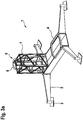
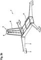
- FIG. 3a two variants of an embodiment of a mounting device 1 according to the invention are shown.
- the mounting device 1 again comprises a base frame 2 with height-adjustable feet 3 to compensate for uneven floors.
- the base frame 2 also has a receptacle 4 on its upper side, to which the uppermost tower segment 10 of the tower of a wind energy plant can be fastened in a vertical arrangement.
- the mounting device 1 still has a receptacle 5 for the horizontal mounting of a wind turbine rotor 13.
- the recording 5 is to attach the Rotor hub 14 arranged thereon so that the assembly of the wind turbine rotor 13 parallel to the pre-assembly of the nacelle 20 on the top tower segment 10, which takes place on the corresponding receptacle 4, can be performed.
- the uppermost tower segment 10 can protrude through the rotor blades 15 of the rotor 13.
- the tower segment 10 mounted on the base frame, together with the gondola 20 already mounted thereon, serves as a counterweight for a partially mounted wind turbine rotor 13.
- the receptacle 5 for the rotor hub 14 of a wind turbine rotor 13 comprises a rotating device 6, with which the rotor hub 14 attached thereto can be rotated about its rotor hub axis.
- the receptacle 5 for the rotor hub 14 is arranged elevated relative to the receptacle 4 for the uppermost tower segment 10, wherein for the production of the distance between the base frame 2 and the actual receptacle 5 for the rotor hub 14 can be accessed on a tower element 7 of a tower system of a building crane ( See embodiment according to FIG. 3a ).
- a tower element 7 of a tower system of a building crane See embodiment according to FIG. 3a .
- the rotating device 6 is arranged on a special support frame 8, which is directly connected to the base frame.
- FIG. 3b A corresponding embodiment variant is in FIG. 3b shown.
- the tower element 7 is detachably attached to the base frame 2. If the tower element 7 is removed, the base frame 2 can be folded by flaps to a level with which it is in a standard 20-foot container can be transported (not shown).
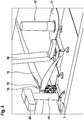
- FIG. 4 is the situation at the installation of a wind turbine with the mounting device 1 according to FIG. 3a shown.
- the mounting device 1 is arranged on the crane footprint 31, that both the preassembled top tower segment 10 with nacelle 20 and the rotor 13 of the large crane 30 can be easily raised.
- the passage height below the mounted on the receptacle 5 of the mounting device 1 rotor 13 is at least 8 m, the maximum height of the rotor 13 is well below 25 m. Due to the appropriate dimensions, on the one hand, the site traffic below the rotor can be done easily, while at the same time comparatively small cranes for the assembly of the rotor 13 can be used.
Landscapes
- Engineering & Computer Science (AREA)
- Life Sciences & Earth Sciences (AREA)
- Sustainable Development (AREA)
- Sustainable Energy (AREA)
- Chemical & Material Sciences (AREA)
- Combustion & Propulsion (AREA)
- Mechanical Engineering (AREA)
- General Engineering & Computer Science (AREA)
- Wind Motors (AREA)
Claims (10)
- Dispositif (1) pour le prémontage de la nacelle (20) d'une éolienne sur un segment de tour supérieur (10), un logement (4) pour la fixation verticale d'un segment de tour (10) de l'éolienne étant disposé au niveau d'un cadre de base (2),
un logement (5) disposé au niveau du cadre de base (2) pour le moyeu de rotor (14) étant prévu pour le montage horizontal du rotor de l'éolienne (13), lequel est disposé à l'opposé du logement (4) pour le segment de tour (10) de telle sorte que le montage du rotor de l'éolienne (13) soit également possible lorsqu'un segment de tour (10) est disposé sur le logement (4) pour le segment de tour (10) et le segment de tour (10) ainsi disposé agissant en tant que contrepoids pendant le montage du rotor de l'éolienne (13),
caractérisé en ce que
le dispositif (1) peut être rabattu et/ou télescopé de telle sorte qu'il présente, dans l'état replié, des dimensions extérieures maximales de 2,5 m x 2,75 m x 10 m. - Dispositif selon la revendication 1, caractérisé en ce que les dimensions extérieures du dispositif (1) dans l'état replié sont choisies de telle sorte que le dispositif (1) puisse être chargé dans un conteneur standard de 40 pieds, de préférence dans un conteneur standard de 20 pieds.
- Dispositif selon la revendication 1 ou 2, caractérisé en ce que le logement (5) pour le moyeu de rotor (14) pour le montage horizontal du rotor de l'éolienne (13) comprend un dispositif rotatif (6) avec lequel le moyeu de rotor (14) fixé au niveau du logement (5) peut être tourné autour de l'axe du moyeu de rotor.
- Dispositif selon l'une quelconque des revendications précédentes, caractérisé en ce que le logement (5) pour le rotor de l'éolienne (13) comprend au moins un élément de tour (7) d'un système de tour d'une grue de chantier, l'élément de tour (7) étant fixé de manière détachable au cadre de base (2) et le logement (5) pour le rotor de l'éolienne (13) étant disposé au niveau de l'extrémité de l'au moins un élément de tour (7) éloignée du cadre de base (2).
- Utilisation d'un dispositif (1) selon l'une quelconque des revendications précédentes, un segment de tour supérieur (10) étant disposé dans une position verticale dans le logement (4), la nacelle (20) étant prémontée au niveau du segment de tour supérieur (10) avant que le segment de tour supérieur (10) ne soit soulevé sur la tour montée jusqu'au segment de tour supérieur et y soit fixé.
- Utilisation selon la revendication 5, caractérisée en ce que le prémontage de la nacelle (20) sur le segment de tour supérieur (10) comprend le montage de la ligne d'entraînement dans la nacelle, le montage et l'orientation de l'arbre du générateur, le montage des barrières de protection, le montage des capteurs de ligne d'entraînement, le montage de câbles de puissance dans la nacelle, le montage des circuits de câbles dans la région de la nacelle, le montage de l'entraînement de réglage azimutal, et/ou le montage de l'éclairage de la nacelle.
- Utilisation selon la revendication 5 ou 6, caractérisée en ce que le prémontage de la nacelle (20) sur le segment de tour supérieur (10) comprend la mise en service et/ou le test de la commande de la nacelle, du système de capteurs et/ou du réglage azimutal.
- Utilisation selon l'une quelconque des revendications 5 à 7, caractérisée en ce que la fixation du segment de tour supérieur (10) sur la tour partiellement montée comprend le montage des vis de la tour, des connecteurs électriques et des connecteurs de rails conducteurs.
- Utilisation selon l'une quelconque des revendications 5 à 8, caractérisée en ce qu'après la fixation du segment de tour supérieur (10) sur la tour partiellement montée, le rotor (13) est fixé de manière rotative sur la nacelle (20) de l'éolienne.
- Utilisation selon l'une quelconque des revendications 5 à 9, caractérisée en ce que le segment de tour supérieur (10) présente une hauteur d'au moins 10 m, de préférence d'au moins 15 m.
Applications Claiming Priority (1)
| Application Number | Priority Date | Filing Date | Title |
|---|---|---|---|
| DE102016006571.0A DE102016006571A1 (de) | 2016-06-01 | 2016-06-01 | Verfahren zum Errichten einer Windenergieanlage sowie Vorrichtung dafür |
Publications (2)
| Publication Number | Publication Date |
|---|---|
| EP3252305A1 EP3252305A1 (fr) | 2017-12-06 |
| EP3252305B1 true EP3252305B1 (fr) | 2019-10-23 |
Family
ID=59021348
Family Applications (1)
| Application Number | Title | Priority Date | Filing Date |
|---|---|---|---|
| EP17174028.5A Active EP3252305B1 (fr) | 2016-06-01 | 2017-06-01 | Dispositif pour l'installation d'une éolienne et utilisation dudit dispositif |
Country Status (4)
| Country | Link |
|---|---|
| EP (1) | EP3252305B1 (fr) |
| DE (1) | DE102016006571A1 (fr) |
| DK (1) | DK3252305T3 (fr) |
| ES (1) | ES2773016T3 (fr) |
Families Citing this family (1)
| Publication number | Priority date | Publication date | Assignee | Title |
|---|---|---|---|---|
| CN119222104A (zh) * | 2023-06-29 | 2024-12-31 | 北京金风科创风电设备有限公司 | 辅助组拼工装和风力发电机组的组拼方法 |
Family Cites Families (8)
| Publication number | Priority date | Publication date | Assignee | Title |
|---|---|---|---|---|
| DE29510415U1 (de) * | 1995-07-03 | 1995-08-24 | ELMO GmbH, 46399 Bocholt | Mobile Stromerzeugungseinrichtung |
| NL1020512C2 (nl) * | 2002-05-01 | 2003-11-06 | Marine Structure Consul | Werkwijze en vaartuig voor het manipuleren van een offshore constructie. |
| DE10321850A1 (de) * | 2003-05-15 | 2004-12-02 | Voss, Uwe | Montagehilfe zum Errichten von Tragmasten von Windenergieanlagen |
| BE1018581A4 (nl) * | 2009-05-28 | 2011-04-05 | Geosea N V | Inrichting en werkwijze voor het assembleren van een bouwwerk op zee. |
| JP5383631B2 (ja) * | 2010-11-18 | 2014-01-08 | 三菱重工業株式会社 | 洋上風車設置用船舶およびこれを用いた洋上風車設置方法 |
| US20120131876A1 (en) * | 2011-10-18 | 2012-05-31 | Jacob Johannes Nies | Hoisting nacelle and tower |
| KR101411472B1 (ko) * | 2012-06-29 | 2014-06-24 | 삼성중공업 주식회사 | 해상 풍력발전기 설치용 선박 |
| KR101614497B1 (ko) * | 2015-06-11 | 2016-04-25 | 김병연 | 풍력발전기의 로터 조립용 허브 받침대 |
-
2016
- 2016-06-01 DE DE102016006571.0A patent/DE102016006571A1/de not_active Withdrawn
-
2017
- 2017-06-01 ES ES17174028T patent/ES2773016T3/es active Active
- 2017-06-01 EP EP17174028.5A patent/EP3252305B1/fr active Active
- 2017-06-01 DK DK17174028.5T patent/DK3252305T3/da active
Non-Patent Citations (1)
| Title |
|---|
| None * |
Also Published As
| Publication number | Publication date |
|---|---|
| DK3252305T3 (da) | 2020-02-03 |
| EP3252305A1 (fr) | 2017-12-06 |
| DE102016006571A1 (de) | 2017-12-07 |
| ES2773016T3 (es) | 2020-07-09 |
Similar Documents
| Publication | Publication Date | Title |
|---|---|---|
| EP2574711B2 (fr) | Tour pour une éolienne | |
| EP3252304B1 (fr) | Système de prémontage horizontal d'un rotor d'éolienne | |
| EP2807107B1 (fr) | Procede et dispositif pour l'installation d'un moyeu de rotor d'une eolienne | |
| EP3042011B1 (fr) | Procédé de montage d'équipements d'une tour | |
| EP2014912A2 (fr) | Eolienne dotée d'une nacelle et procédé de fabrication d'une telle éolienne | |
| AT506625A4 (de) | Instandhaltungsplattform | |
| EP3208404B1 (fr) | Procédé et dispositif de montage d'un mât tubulaire | |
| DE19636240A1 (de) | Maste für Windkraftanlagen | |
| EP3853472B1 (fr) | Segment de tour d'éolienne pour tour d'éolienne et procédé | |
| EP3399185A1 (fr) | Enceinte pour une nacelle d'une éolienne | |
| EP3252305B1 (fr) | Dispositif pour l'installation d'une éolienne et utilisation dudit dispositif | |
| DE10321850A1 (de) | Montagehilfe zum Errichten von Tragmasten von Windenergieanlagen | |
| DE102019219722A1 (de) | Verfahren zum Errichten einer Windenergieanlage | |
| EP3056611B1 (fr) | Dispositif de couplage destiné à relier une structure porteuse à une fondation au fond de la mer | |
| EP3382195B1 (fr) | Utilisation des moyens de transport lors de la construction des éoliennes et aide au montage | |
| EP2653715B1 (fr) | Tour pour une éolienne ainsi que le procédé de montage de cette tour | |
| WO2004076781A1 (fr) | Dispositif pour eriger une eolienne | |
| EP3581794B1 (fr) | Système de montage et procédé de montage d'un rotor en étoile pour une éolienne | |
| EP1384883B1 (fr) | Barge de transport pour nacelles d'éoliennes marines et procédé associé | |
| EP3379078A1 (fr) | Procédé et dispositif de montage d'une tour d'éolienne et tour d'éolienne | |
| DE10206242B4 (de) | Windkraftanlage und zugehöriger Mast | |
| EP4118330B1 (fr) | Procédé d'érection d'une centrale éolienne | |
| EP3704333B1 (fr) | Procédé d'édification d'une tour ayant une section de tour en plusieurs parties | |
| DE102020006544A1 (de) | Verfahren und Ausrüstung zum Errichten, Ausrüsten und Betreiben von Binnenwindanlagen großer Höhen und Leistung | |
| DE202004009011U1 (de) | Solarhalle mit Faltgerüst |
Legal Events
| Date | Code | Title | Description |
|---|---|---|---|
| PUAI | Public reference made under article 153(3) epc to a published international application that has entered the european phase |
Free format text: ORIGINAL CODE: 0009012 |
|
| STAA | Information on the status of an ep patent application or granted ep patent |
Free format text: STATUS: THE APPLICATION HAS BEEN PUBLISHED |
|
| AK | Designated contracting states |
Kind code of ref document: A1 Designated state(s): AL AT BE BG CH CY CZ DE DK EE ES FI FR GB GR HR HU IE IS IT LI LT LU LV MC MK MT NL NO PL PT RO RS SE SI SK SM TR |
|
| AX | Request for extension of the european patent |
Extension state: BA ME |
|
| STAA | Information on the status of an ep patent application or granted ep patent |
Free format text: STATUS: REQUEST FOR EXAMINATION WAS MADE |
|
| 17P | Request for examination filed |
Effective date: 20180601 |
|
| RBV | Designated contracting states (corrected) |
Designated state(s): AL AT BE BG CH CY CZ DE DK EE ES FI FR GB GR HR HU IE IS IT LI LT LU LV MC MK MT NL NO PL PT RO RS SE SI SK SM TR |
|
| GRAP | Despatch of communication of intention to grant a patent |
Free format text: ORIGINAL CODE: EPIDOSNIGR1 |
|
| STAA | Information on the status of an ep patent application or granted ep patent |
Free format text: STATUS: GRANT OF PATENT IS INTENDED |
|
| INTG | Intention to grant announced |
Effective date: 20190521 |
|
| GRAS | Grant fee paid |
Free format text: ORIGINAL CODE: EPIDOSNIGR3 |
|
| GRAA | (expected) grant |
Free format text: ORIGINAL CODE: 0009210 |
|
| STAA | Information on the status of an ep patent application or granted ep patent |
Free format text: STATUS: THE PATENT HAS BEEN GRANTED |
|
| AK | Designated contracting states |
Kind code of ref document: B1 Designated state(s): AL AT BE BG CH CY CZ DE DK EE ES FI FR GB GR HR HU IE IS IT LI LT LU LV MC MK MT NL NO PL PT RO RS SE SI SK SM TR |
|
| REG | Reference to a national code |
Ref country code: GB Ref legal event code: FG4D Free format text: NOT ENGLISH |
|
| REG | Reference to a national code |
Ref country code: CH Ref legal event code: EP |
|
| REG | Reference to a national code |
Ref country code: IE Ref legal event code: FG4D Free format text: LANGUAGE OF EP DOCUMENT: GERMAN |
|
| REG | Reference to a national code |
Ref country code: DE Ref legal event code: R096 Ref document number: 502017002628 Country of ref document: DE |
|
| REG | Reference to a national code |
Ref country code: AT Ref legal event code: REF Ref document number: 1193919 Country of ref document: AT Kind code of ref document: T Effective date: 20191115 |
|
| REG | Reference to a national code |
Ref country code: DK Ref legal event code: T3 Effective date: 20200131 |
|
| REG | Reference to a national code |
Ref country code: NL Ref legal event code: MP Effective date: 20191023 |
|
| REG | Reference to a national code |
Ref country code: LT Ref legal event code: MG4D |
|
| PG25 | Lapsed in a contracting state [announced via postgrant information from national office to epo] |
Ref country code: SE Free format text: LAPSE BECAUSE OF FAILURE TO SUBMIT A TRANSLATION OF THE DESCRIPTION OR TO PAY THE FEE WITHIN THE PRESCRIBED TIME-LIMIT Effective date: 20191023 Ref country code: LV Free format text: LAPSE BECAUSE OF FAILURE TO SUBMIT A TRANSLATION OF THE DESCRIPTION OR TO PAY THE FEE WITHIN THE PRESCRIBED TIME-LIMIT Effective date: 20191023 Ref country code: NL Free format text: LAPSE BECAUSE OF FAILURE TO SUBMIT A TRANSLATION OF THE DESCRIPTION OR TO PAY THE FEE WITHIN THE PRESCRIBED TIME-LIMIT Effective date: 20191023 Ref country code: LT Free format text: LAPSE BECAUSE OF FAILURE TO SUBMIT A TRANSLATION OF THE DESCRIPTION OR TO PAY THE FEE WITHIN THE PRESCRIBED TIME-LIMIT Effective date: 20191023 Ref country code: GR Free format text: LAPSE BECAUSE OF FAILURE TO SUBMIT A TRANSLATION OF THE DESCRIPTION OR TO PAY THE FEE WITHIN THE PRESCRIBED TIME-LIMIT Effective date: 20200124 Ref country code: PL Free format text: LAPSE BECAUSE OF FAILURE TO SUBMIT A TRANSLATION OF THE DESCRIPTION OR TO PAY THE FEE WITHIN THE PRESCRIBED TIME-LIMIT Effective date: 20191023 Ref country code: NO Free format text: LAPSE BECAUSE OF FAILURE TO SUBMIT A TRANSLATION OF THE DESCRIPTION OR TO PAY THE FEE WITHIN THE PRESCRIBED TIME-LIMIT Effective date: 20200123 Ref country code: PT Free format text: LAPSE BECAUSE OF FAILURE TO SUBMIT A TRANSLATION OF THE DESCRIPTION OR TO PAY THE FEE WITHIN THE PRESCRIBED TIME-LIMIT Effective date: 20200224 Ref country code: FI Free format text: LAPSE BECAUSE OF FAILURE TO SUBMIT A TRANSLATION OF THE DESCRIPTION OR TO PAY THE FEE WITHIN THE PRESCRIBED TIME-LIMIT Effective date: 20191023 Ref country code: BG Free format text: LAPSE BECAUSE OF FAILURE TO SUBMIT A TRANSLATION OF THE DESCRIPTION OR TO PAY THE FEE WITHIN THE PRESCRIBED TIME-LIMIT Effective date: 20200123 |
|
| PG25 | Lapsed in a contracting state [announced via postgrant information from national office to epo] |
Ref country code: HR Free format text: LAPSE BECAUSE OF FAILURE TO SUBMIT A TRANSLATION OF THE DESCRIPTION OR TO PAY THE FEE WITHIN THE PRESCRIBED TIME-LIMIT Effective date: 20191023 Ref country code: IS Free format text: LAPSE BECAUSE OF FAILURE TO SUBMIT A TRANSLATION OF THE DESCRIPTION OR TO PAY THE FEE WITHIN THE PRESCRIBED TIME-LIMIT Effective date: 20200224 Ref country code: RS Free format text: LAPSE BECAUSE OF FAILURE TO SUBMIT A TRANSLATION OF THE DESCRIPTION OR TO PAY THE FEE WITHIN THE PRESCRIBED TIME-LIMIT Effective date: 20191023 |
|
| PG25 | Lapsed in a contracting state [announced via postgrant information from national office to epo] |
Ref country code: AL Free format text: LAPSE BECAUSE OF FAILURE TO SUBMIT A TRANSLATION OF THE DESCRIPTION OR TO PAY THE FEE WITHIN THE PRESCRIBED TIME-LIMIT Effective date: 20191023 |
|
| REG | Reference to a national code |
Ref country code: ES Ref legal event code: FG2A Ref document number: 2773016 Country of ref document: ES Kind code of ref document: T3 Effective date: 20200709 |
|
| REG | Reference to a national code |
Ref country code: DE Ref legal event code: R097 Ref document number: 502017002628 Country of ref document: DE |
|
| PG2D | Information on lapse in contracting state deleted |
Ref country code: IS |
|
| PG25 | Lapsed in a contracting state [announced via postgrant information from national office to epo] |
Ref country code: CZ Free format text: LAPSE BECAUSE OF FAILURE TO SUBMIT A TRANSLATION OF THE DESCRIPTION OR TO PAY THE FEE WITHIN THE PRESCRIBED TIME-LIMIT Effective date: 20191023 Ref country code: RO Free format text: LAPSE BECAUSE OF FAILURE TO SUBMIT A TRANSLATION OF THE DESCRIPTION OR TO PAY THE FEE WITHIN THE PRESCRIBED TIME-LIMIT Effective date: 20191023 Ref country code: EE Free format text: LAPSE BECAUSE OF FAILURE TO SUBMIT A TRANSLATION OF THE DESCRIPTION OR TO PAY THE FEE WITHIN THE PRESCRIBED TIME-LIMIT Effective date: 20191023 Ref country code: IS Free format text: LAPSE BECAUSE OF FAILURE TO SUBMIT A TRANSLATION OF THE DESCRIPTION OR TO PAY THE FEE WITHIN THE PRESCRIBED TIME-LIMIT Effective date: 20200223 |
|
| PGFP | Annual fee paid to national office [announced via postgrant information from national office to epo] |
Ref country code: DE Payment date: 20200623 Year of fee payment: 4 Ref country code: DK Payment date: 20200622 Year of fee payment: 4 Ref country code: FR Payment date: 20200623 Year of fee payment: 4 |
|
| PLBE | No opposition filed within time limit |
Free format text: ORIGINAL CODE: 0009261 |
|
| STAA | Information on the status of an ep patent application or granted ep patent |
Free format text: STATUS: NO OPPOSITION FILED WITHIN TIME LIMIT |
|
| PG25 | Lapsed in a contracting state [announced via postgrant information from national office to epo] |
Ref country code: SK Free format text: LAPSE BECAUSE OF FAILURE TO SUBMIT A TRANSLATION OF THE DESCRIPTION OR TO PAY THE FEE WITHIN THE PRESCRIBED TIME-LIMIT Effective date: 20191023 Ref country code: SM Free format text: LAPSE BECAUSE OF FAILURE TO SUBMIT A TRANSLATION OF THE DESCRIPTION OR TO PAY THE FEE WITHIN THE PRESCRIBED TIME-LIMIT Effective date: 20191023 Ref country code: IT Free format text: LAPSE BECAUSE OF FAILURE TO SUBMIT A TRANSLATION OF THE DESCRIPTION OR TO PAY THE FEE WITHIN THE PRESCRIBED TIME-LIMIT Effective date: 20191023 |
|
| 26N | No opposition filed |
Effective date: 20200724 |
|
| PGFP | Annual fee paid to national office [announced via postgrant information from national office to epo] |
Ref country code: ES Payment date: 20200717 Year of fee payment: 4 |
|
| PG25 | Lapsed in a contracting state [announced via postgrant information from national office to epo] |
Ref country code: SI Free format text: LAPSE BECAUSE OF FAILURE TO SUBMIT A TRANSLATION OF THE DESCRIPTION OR TO PAY THE FEE WITHIN THE PRESCRIBED TIME-LIMIT Effective date: 20191023 |
|
| PG25 | Lapsed in a contracting state [announced via postgrant information from national office to epo] |
Ref country code: MC Free format text: LAPSE BECAUSE OF FAILURE TO SUBMIT A TRANSLATION OF THE DESCRIPTION OR TO PAY THE FEE WITHIN THE PRESCRIBED TIME-LIMIT Effective date: 20191023 |
|
| REG | Reference to a national code |
Ref country code: CH Ref legal event code: PL |
|
| PG25 | Lapsed in a contracting state [announced via postgrant information from national office to epo] |
Ref country code: LU Free format text: LAPSE BECAUSE OF NON-PAYMENT OF DUE FEES Effective date: 20200601 |
|
| REG | Reference to a national code |
Ref country code: BE Ref legal event code: MM Effective date: 20200630 |
|
| PG25 | Lapsed in a contracting state [announced via postgrant information from national office to epo] |
Ref country code: IE Free format text: LAPSE BECAUSE OF NON-PAYMENT OF DUE FEES Effective date: 20200601 Ref country code: LI Free format text: LAPSE BECAUSE OF NON-PAYMENT OF DUE FEES Effective date: 20200630 Ref country code: CH Free format text: LAPSE BECAUSE OF NON-PAYMENT OF DUE FEES Effective date: 20200630 |
|
| PG25 | Lapsed in a contracting state [announced via postgrant information from national office to epo] |
Ref country code: BE Free format text: LAPSE BECAUSE OF NON-PAYMENT OF DUE FEES Effective date: 20200630 |
|
| REG | Reference to a national code |
Ref country code: DE Ref legal event code: R119 Ref document number: 502017002628 Country of ref document: DE |
|
| REG | Reference to a national code |
Ref country code: DK Ref legal event code: EBP Effective date: 20210630 |
|
| GBPC | Gb: european patent ceased through non-payment of renewal fee |
Effective date: 20210601 |
|
| PG25 | Lapsed in a contracting state [announced via postgrant information from national office to epo] |
Ref country code: GB Free format text: LAPSE BECAUSE OF NON-PAYMENT OF DUE FEES Effective date: 20210601 Ref country code: DE Free format text: LAPSE BECAUSE OF NON-PAYMENT OF DUE FEES Effective date: 20220101 |
|
| PG25 | Lapsed in a contracting state [announced via postgrant information from national office to epo] |
Ref country code: TR Free format text: LAPSE BECAUSE OF FAILURE TO SUBMIT A TRANSLATION OF THE DESCRIPTION OR TO PAY THE FEE WITHIN THE PRESCRIBED TIME-LIMIT Effective date: 20191023 Ref country code: MT Free format text: LAPSE BECAUSE OF FAILURE TO SUBMIT A TRANSLATION OF THE DESCRIPTION OR TO PAY THE FEE WITHIN THE PRESCRIBED TIME-LIMIT Effective date: 20191023 Ref country code: FR Free format text: LAPSE BECAUSE OF NON-PAYMENT OF DUE FEES Effective date: 20210630 Ref country code: CY Free format text: LAPSE BECAUSE OF FAILURE TO SUBMIT A TRANSLATION OF THE DESCRIPTION OR TO PAY THE FEE WITHIN THE PRESCRIBED TIME-LIMIT Effective date: 20191023 |
|
| PG25 | Lapsed in a contracting state [announced via postgrant information from national office to epo] |
Ref country code: MK Free format text: LAPSE BECAUSE OF FAILURE TO SUBMIT A TRANSLATION OF THE DESCRIPTION OR TO PAY THE FEE WITHIN THE PRESCRIBED TIME-LIMIT Effective date: 20191023 |
|
| REG | Reference to a national code |
Ref country code: ES Ref legal event code: FD2A Effective date: 20220727 |
|
| PG25 | Lapsed in a contracting state [announced via postgrant information from national office to epo] |
Ref country code: DK Free format text: LAPSE BECAUSE OF NON-PAYMENT OF DUE FEES Effective date: 20210630 |
|
| PG25 | Lapsed in a contracting state [announced via postgrant information from national office to epo] |
Ref country code: ES Free format text: LAPSE BECAUSE OF NON-PAYMENT OF DUE FEES Effective date: 20210602 |
|
| REG | Reference to a national code |
Ref country code: AT Ref legal event code: MM01 Ref document number: 1193919 Country of ref document: AT Kind code of ref document: T Effective date: 20220601 |
|
| PG25 | Lapsed in a contracting state [announced via postgrant information from national office to epo] |
Ref country code: AT Free format text: LAPSE BECAUSE OF NON-PAYMENT OF DUE FEES Effective date: 20220601 |