EP2653732A2 - Agencement de soupape présentant au moins deux unités de soupape avec différents débits nominaux - Google Patents
Agencement de soupape présentant au moins deux unités de soupape avec différents débits nominaux Download PDFInfo
- Publication number
- EP2653732A2 EP2653732A2 EP13000512.7A EP13000512A EP2653732A2 EP 2653732 A2 EP2653732 A2 EP 2653732A2 EP 13000512 A EP13000512 A EP 13000512A EP 2653732 A2 EP2653732 A2 EP 2653732A2
- Authority
- EP
- European Patent Office
- Prior art keywords
- valve
- units
- valve unit
- nominal flow
- unit
- Prior art date
- Legal status (The legal status is an assumption and is not a legal conclusion. Google has not performed a legal analysis and makes no representation as to the accuracy of the status listed.)
- Withdrawn
Links
- 238000000034 method Methods 0.000 claims abstract description 5
- 239000012530 fluid Substances 0.000 claims description 11
- 230000007704 transition Effects 0.000 description 5
- 238000007789 sealing Methods 0.000 description 2
- 238000012360 testing method Methods 0.000 description 2
- 238000013459 approach Methods 0.000 description 1
- 230000000712 assembly Effects 0.000 description 1
- 238000000429 assembly Methods 0.000 description 1
- 238000004891 communication Methods 0.000 description 1
- 230000006378 damage Effects 0.000 description 1
- 230000002950 deficient Effects 0.000 description 1
- 230000001419 dependent effect Effects 0.000 description 1
- 238000013461 design Methods 0.000 description 1
- 238000011161 development Methods 0.000 description 1
- 238000003780 insertion Methods 0.000 description 1
- 230000037431 insertion Effects 0.000 description 1
- 238000002955 isolation Methods 0.000 description 1
- 230000005405 multipole Effects 0.000 description 1
- 238000012797 qualification Methods 0.000 description 1
- 238000000926 separation method Methods 0.000 description 1
- 230000003068 static effect Effects 0.000 description 1
- 238000013022 venting Methods 0.000 description 1
Images



Classifications
-
- F—MECHANICAL ENGINEERING; LIGHTING; HEATING; WEAPONS; BLASTING
- F15—FLUID-PRESSURE ACTUATORS; HYDRAULICS OR PNEUMATICS IN GENERAL
- F15B—SYSTEMS ACTING BY MEANS OF FLUIDS IN GENERAL; FLUID-PRESSURE ACTUATORS, e.g. SERVOMOTORS; DETAILS OF FLUID-PRESSURE SYSTEMS, NOT OTHERWISE PROVIDED FOR
- F15B13/00—Details of servomotor systems ; Valves for servomotor systems
- F15B13/02—Fluid distribution or supply devices characterised by their adaptation to the control of servomotors
- F15B13/06—Fluid distribution or supply devices characterised by their adaptation to the control of servomotors for use with two or more servomotors
- F15B13/08—Assemblies of units, each for the control of a single servomotor only
- F15B13/0803—Modular units
- F15B13/0807—Manifolds
- F15B13/0814—Monoblock manifolds
-
- F—MECHANICAL ENGINEERING; LIGHTING; HEATING; WEAPONS; BLASTING
- F15—FLUID-PRESSURE ACTUATORS; HYDRAULICS OR PNEUMATICS IN GENERAL
- F15B—SYSTEMS ACTING BY MEANS OF FLUIDS IN GENERAL; FLUID-PRESSURE ACTUATORS, e.g. SERVOMOTORS; DETAILS OF FLUID-PRESSURE SYSTEMS, NOT OTHERWISE PROVIDED FOR
- F15B13/00—Details of servomotor systems ; Valves for servomotor systems
- F15B13/02—Fluid distribution or supply devices characterised by their adaptation to the control of servomotors
- F15B13/06—Fluid distribution or supply devices characterised by their adaptation to the control of servomotors for use with two or more servomotors
- F15B13/08—Assemblies of units, each for the control of a single servomotor only
- F15B13/0803—Modular units
- F15B13/0832—Modular valves
- F15B13/0839—Stacked plate type valves
-
- F—MECHANICAL ENGINEERING; LIGHTING; HEATING; WEAPONS; BLASTING
- F15—FLUID-PRESSURE ACTUATORS; HYDRAULICS OR PNEUMATICS IN GENERAL
- F15B—SYSTEMS ACTING BY MEANS OF FLUIDS IN GENERAL; FLUID-PRESSURE ACTUATORS, e.g. SERVOMOTORS; DETAILS OF FLUID-PRESSURE SYSTEMS, NOT OTHERWISE PROVIDED FOR
- F15B13/00—Details of servomotor systems ; Valves for servomotor systems
- F15B13/02—Fluid distribution or supply devices characterised by their adaptation to the control of servomotors
- F15B13/06—Fluid distribution or supply devices characterised by their adaptation to the control of servomotors for use with two or more servomotors
- F15B13/08—Assemblies of units, each for the control of a single servomotor only
- F15B13/0803—Modular units
- F15B13/0878—Assembly of modular units
- F15B13/0896—Assembly of modular units using different types or sizes of valves
-
- F—MECHANICAL ENGINEERING; LIGHTING; HEATING; WEAPONS; BLASTING
- F16—ENGINEERING ELEMENTS AND UNITS; GENERAL MEASURES FOR PRODUCING AND MAINTAINING EFFECTIVE FUNCTIONING OF MACHINES OR INSTALLATIONS; THERMAL INSULATION IN GENERAL
- F16K—VALVES; TAPS; COCKS; ACTUATING-FLOATS; DEVICES FOR VENTING OR AERATING
- F16K27/00—Construction of housing; Use of materials therefor
- F16K27/003—Housing formed from a plurality of the same valve elements
-
- F—MECHANICAL ENGINEERING; LIGHTING; HEATING; WEAPONS; BLASTING
- F16—ENGINEERING ELEMENTS AND UNITS; GENERAL MEASURES FOR PRODUCING AND MAINTAINING EFFECTIVE FUNCTIONING OF MACHINES OR INSTALLATIONS; THERMAL INSULATION IN GENERAL
- F16K—VALVES; TAPS; COCKS; ACTUATING-FLOATS; DEVICES FOR VENTING OR AERATING
- F16K3/00—Gate valves or sliding valves, i.e. cut-off apparatus with closing members having a sliding movement along the seat for opening and closing
- F16K3/22—Gate valves or sliding valves, i.e. cut-off apparatus with closing members having a sliding movement along the seat for opening and closing with sealing faces shaped as surfaces of solids of revolution
- F16K3/24—Gate valves or sliding valves, i.e. cut-off apparatus with closing members having a sliding movement along the seat for opening and closing with sealing faces shaped as surfaces of solids of revolution with cylindrical valve members
-
- F—MECHANICAL ENGINEERING; LIGHTING; HEATING; WEAPONS; BLASTING
- F16—ENGINEERING ELEMENTS AND UNITS; GENERAL MEASURES FOR PRODUCING AND MAINTAINING EFFECTIVE FUNCTIONING OF MACHINES OR INSTALLATIONS; THERMAL INSULATION IN GENERAL
- F16K—VALVES; TAPS; COCKS; ACTUATING-FLOATS; DEVICES FOR VENTING OR AERATING
- F16K3/00—Gate valves or sliding valves, i.e. cut-off apparatus with closing members having a sliding movement along the seat for opening and closing
- F16K3/30—Details
- F16K3/314—Forms or constructions of slides; Attachment of the slide to the spindle
Definitions
- the present invention relates to a valve assembly comprising at least two valve units having different nominal flow rates and a method of constructing two such valve units.
- the invention is based on a valve arrangement with a connection plate which has at least one connection plate mounting surface which defines a plurality of mounting positions arranged side by side in a row, each equipped with an electrically or fluidically (eg pneumatically) operable valve unit (eg a multi-way valve).
- an electrically or fluidically (eg pneumatically) operable valve unit eg a multi-way valve
- the connection plate at least one connectable to a pressure source terminal plate feed channel and at least one connectable to the atmosphere connection plate vent channel, each leading to each of the placement places, and of each placement at least one of the terminal plate passing through and connectable to a consumer individual connection plates Working channel goes out, the fluid loading is controlled by the valve assembly mounted on the associated placement.
- a valve arrangement is for example from the WO 2007/140851 A1 known.
- valve-connection plate system The field of application of such valve arrangements extends primarily to such pneumatic or generally fluidic systems, in which several pressure medium units, such as pressure medium cylinders or rotary drives, are to be controlled via valves.
- pressure medium units such as pressure medium cylinders or rotary drives
- valve-connection plate system a local summary of the required valves to a compact unit in the form of a valve assembly has proven.
- valve units with different nominal flow rates are combined.
- a nominal flow rate can be, for example, the maximum flow per minute in [Nl / min] at a given inlet pressure (eg 7 bar), a certain pressure drop across the valve (eg 1 bar), at a certain air temperature (eg 20 ° C) and humidity (eg 0%).
- valve units having different nominal flow rates it is desirable to obtain valve units having different nominal flow rates in the simplest possible way and to combine them in a valve arrangement.
- valve arrangement comprising at least two valve units with different nominal flow rates and a method for constructing two such valve units with the features of the independent claims are proposed.
- Advantageous embodiments are the subject of the dependent claims and the following description.
- valve functionality of the valve unit is realized by a longitudinal slide valve with a valve slide axially slidably mounted valve slide, wherein one, in particular annular, the nominal flow rate defining surface formed in an open state of the valve unit between a control edge of the valve spool and an inner edge of the valve bore is where valve units, which belong to different nominal flow rates, differ by the area of the nominal flow rate defining surface.
- the surface area of the nominal flow rate defining surface is particularly simple and expediently changed by changing the distance of the control edge of the valve slide from the inner edge of the valve bore. It is particularly advantageous if the transition to a, in particular next, higher nominal flow rate, the projection of the distance to a longitudinal or transverse axis remains unchanged. In other words, either only the projection of the distance to a transverse or only the projection of the distance to a longitudinal axis changes during the transition to the higher nominal flow rate.
- a change in the surface area of the nominal flow rate defining surface can be achieved particularly easily by an axial extension of the valve spool and / or the valve bore.
- An axial extension is known from geometry. The stretching is performed by making a perpendicular to the reference axis from each point of the object and stretching the distance of the point from the reference axis with the stretch factor.
- the transition to the higher nominal flow rate is preferably carried out by only one axial extension.
- the overall length (at radial enlargement) or the overall width (at axial enlargement) of the valve unit can advantageously be kept the same.
- the height of the valve unit can advantageously always be kept the same, since it is usually high enough anyway to accommodate the longitudinal slide valve.
- the invention makes it possible in a very simple way to develop and construct numerous valve units with different nominal flow rates, which may be higher or lower, starting from a referential valve unit. Test results can be transferred. For example, a qualification, e.g. Endurance test, only required on the valve version with the longest spool stroke. Due to this worst-case approach, all valve variants with smaller spool strokes are less critical with regard to wear-related failure. The so-called "time to market" can be reduced.
- valve units with different nominal flow rates which can be selected depending on the application, can be realized in a valve arrangement.
- appearance of valve units having different nominal flow rates may be similar or similar.
- a higher degree of identical parts use, for example of slide seals, connection elements, actuators, etc., can be achieved.
- FIGS. 1 and 2 are described in the following coherently and comprehensively, wherein like elements are provided with the same reference numerals.
- a valve unit 100 according to a preferred embodiment of the invention is shown in a schematic side view.
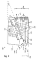
- a valve assembly 300 is shown according to a preferred embodiment of the invention, wherein the valve unit 100 are shown in a schematic side view and a connection plate 200 in a longitudinal sectional view.
- the longitudinal sectional view of the terminal plate 200 in FIG. 2 runs along a loading slot 221a of a terminal plate mounting surface 221.
- the terminal plate mounting area 221 has a plurality of loading locations 221a, wherein a valve unit 100 can be mounted at each loading station 221a.
- a connection plate 200 is combined with a plurality of valve units 100 to form a valve assembly 300.
- the individual valve units are arranged side by side in a direction perpendicular to the plane of the drawing.
- the valve unit 100 is here electrically actuated and consists of a pilot module 110 and a valve module 120, which are preferably structurally separated from each other.
- the pilot module 110 contains those components that are needed for controlling the valve unit, whereas the components for performing the valve functionality are structurally combined in the valve module 120.
- the components to fulfill the valve functionality form a longitudinal slide valve, as in FIG. 3 shown.
- valve module 120 a spool bore is provided, in which a valve spool is arranged to be movable back and forth, as in FIG. 3 is shown.
- the valve module 120 has a valve unit mounting surface 121, which is placed in the assembly of the valve unit 100 at one of the mounting locations 221a of the terminal plate 200 with the terminal plate mounting surface 221 in arrangement and interacts.
- valve unit mounting surface 121 in particular openings are provided which are connected to the slide bore and which are in different ways in fluid communication with each other by different positions of the slide. This is well known in the art for multiway valves.
- the valve module 120 further has on its valve module top side 122 control openings for the valve spool, by the actuation of the valve spool in particular to achieve different switching positions can be achieved.
- the pilot module 110 has a recess 111 for receiving the valve module 120.
- a boundary of the recess forms a pilot module bottom 112, which interacts with the valve module top 122.
- the pilot module 110 can also be connected in particular to a connection plate feed channel.
- valve module 120 As shown, the insertion of the valve module 120 into the pilot module 110 is substantially perpendicular to the surface to be sealed between 112 and 122, so that there may be provided a static sealing element which is not stressed by the assembly to train or shear.
- the valve module 120 can be inserted into the pilot module 110 and removed from it again without destruction.
- connection plate run a connectable to a pressure source (for example, a compressed air compressor) terminal plate feed channel 202 and two connectable to the atmosphere terminal plate venting channels 203, each of which opens out to each of the placement slots 22 1 a.
- a pressure source for example, a compressed air compressor
- port plate working channels 204 which extend from the loading station 221a and are connected to fluid ports 204a connectable to a consumer. The fluid loading of the port plate working channels 204 is controlled by the valve unit 100 mounted on the associated hopper 221a.
- the valve unit mounting surface 121 faces a valve unit top 101 when the valve module 120 is inserted into the pilot module 110, that is, the valve unit is formed.
- the valve unit mounting surface 121 and the valve unit top 101 are not parallel, but include an angle which in the example shown is approximately 20 °. This essentially results in a wedge shape of the valve unit 100 in longitudinal section along the valve unit mounting surface 121. In this way, a smaller valve unit height 105 and a larger valve unit height 106 are defined between the valve unit mounting surface 121 and the valve unit top 101.
- a change of angle allows for valve units with different nominal flow rates to influence the dimensions of the valve unit advantageous.
- the angle can be, for example, up to 45 °.
- the valve unit 100 has, in the region of the larger valve unit height 106, electrical connection means 107, for example pressure pins, which lead electrical contacts of the pilot module 110 of the valve unit to the outside.
- the terminal plate mounting surface 221 is opposed to a terminal plate bottom 201.
- terminal plate loading area 221 and terminal plate bottom 201 are not parallel but also enclose an angle.
- the size of this angle is suitably corresponds to the corresponding angle associated valve units to achieve a total of a rectangular shape.
- This essentially leads to a wedge shape of the connection plate 200 in a longitudinal section along a placement space 221a. In this way, a smaller terminal plate height 206 and a larger terminal plate height 205 are defined between the terminal plate mounting surface 221 and the opposite terminal plate bottom 201.
- the smaller port plate height 206 defines, along with the larger valve unit height 106, a height of the valve assembly 300.
- the valve assembly in the mounted state has a substantially rectangular longitudinal sectional area along a loading place.
- valve unit fastening means 113 are provided in the region of the larger valve unit height 106, and a valve unit fastening means 114 in the region of the smaller valve unit height 105.
- the valve unit attachment means 113, 114 are used for secure mounting of the valve unit 100 to the connection plate 200.
- connection plate fastening means 213 are provided in the area of the smaller connection plate height 206, and a connection plate fastening means 214 in the region of the larger connection plate height 205, which respectively interacts with the associated valve unit fastening means in order to secure the valve unit 100 in the mounted state to fix.
- valve unit attachment means 113 is formed in the region of the larger valve unit height 106 as an element of a hook connection 113, 213, here as a hook 113, which engage in the associated connection plate fastening means 213 can.
- the provided in the region of the smaller valve unit height 105 valve unit attachment means 114 is designed here as a screw which can engage in the associated terminal plate attachment means 214.
- connection plate fastening means 213 provided in the region of the smaller connection plate height 206 is designed as an element of a hook connection, here as a hook 213, which can be hooked to the associated hook 113 of the valve unit 100.
- the connection plate fastening means 214 provided in the region of the larger connection plate height 205 is designed as a threaded bore, into which the screw 114 of the valve unit 100 can be screwed.
- connection plate fastening means provided in the region of the larger connection plate height 205 and the corresponding valve unit fastening means provided in the region of the smaller valve unit height 105 may together also form a bayonet closure, wherein the valve unit fastening means is preferably designed as a bolt, for example, with projecting pins, which in one Opening engages with corresponding grooves. Other types of bayonet locks are preferred.
- connection plate 200 a recess 207 for receiving electrical connection means 208 is furthermore provided in the region of the smaller connection plate height 206.
- the connecting means 208 are exemplified here as a board, are provided on the supply lines for each pilot module of a mounted valve unit. The supply lines on the board in this way connect the pilot modules via their electrical connection means 107 and, for example, via electrical connection means 503 FIG. 5 with a control circuit (not shown), which detects the control of the mounted valve units.
- connection plate at a loading place 221a It can be seen in the longitudinal sectional view along a placement space that a substantial height requirement of the connection plate at a loading place 221a is caused by the fluid connections 204a to the consumers.
- the electrical connection requires relatively little space, so that advantageous space utilization is achieved in the context of the invention by arranging the components relating to the fluid substantially in the region of the larger connection plate height 205 and the components relating to the electrical system in the area of the smaller connection plate height 206 are.
- valve unit 100 in which the control components of the pilot module define the significant height requirements, whereas the fluid concerning relatively small channels sufficient, which also allows a total arrangement in a wedge shape.
- pilot module Due to the illustrated structural separation of pilot module on the one hand and valve module on the other hand, defective elements can be easily and inexpensively replaced. In essence, only the valve module is subject to wear, whereas the pilot module has substantially a relatively long life. This leads to a significant cost savings.
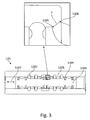
- a preferred longitudinal slide valve is shown schematically in longitudinal section, which may be in particular a longitudinal section through a valve module 120.
- the valve module 120 has a housing 1201 with a valve bore 1202.
- open (here four) channels ie feed channel, vent channel, working channels
- the mouth areas 1207 here annular or gurbringförmig extend around the valve bore.
- a valve slide 1203 equipped with seals 1204 (eg, sealing rings) is mounted so as to be axially displaceable.
- the (here six) seals 1204 surround the valve spool 1203 and are arranged in corresponding recesses. The movement of the valve spool to actuate the valve is controlled by lateral fluid admission, here by the pilot module.
- An area F which determines the nominal flow rate of the valve module 120 and thus of the associated valve unit is formed in the open state of the valve shown by the area between a so-called control edge 1205 of the valve slide and an inner edge 1206 of the valve bore.
- the valve bore 1202 and the valve slide 1203 are substantially cylindrical, so that for the nominal flow rate determining surface results in a ring shape, which corresponds to a truncated cone surface in the present example, but may also correspond to a cylinder jacket surface or a circular ring shape.
- the distance between the control edge 1205 of the valve spool and the inner edge 1206 of the valve bore in the open state of the valve corresponds to the length of the arrow F.
- valve units with different nominal flow rates differ here by the area of their surface defining the nominal flow rate.
- the invention makes use of the concept of axial stretching known from geometry, whereby only exactly one axial elongation is always carried out during the transition to a (in particular nearest) higher nominal flow rate.
- axles for the axial stretching are available, as in FIG. 4 shown, a longitudinal axis L (ie along the direction of movement of the valve spool 1203), or a transverse axis Q (ie transversely to the direction of movement of the valve spool 1203) on.
- FIG. 4 are three valve modules or longitudinal slide valves 120, 130, 140 shown in longitudinal section, which are generated by axial stretching of the longitudinal slide and slide holes.
- the valve module 130 has a (compared to the valve module 120 in particular next) higher nominal flow rate and emerges from the valve module 120 by axial stretching on a transverse axis Q out.
- the axial extension on the transverse axis Q leads to an extension (axial enlargement) of the valve module, but width and height (as well as the diameter of the valve spool and the slide bore) remain the same.
- the extension increases the distance between the control edge of the valve spool and the inner edge of the spool bore and the projection of the distance to the longitudinal axis and thereby the area of the surface F, but not their peripheries and not the projection of the distance to the transverse axis.
- the width of the valve module and thus of the associated valve unit ie the extent in the plane of drawing into FIG. 1 ) remains.
- the valve module 140 has a (compared to the valve module 130 in particular next) higher nominal flow rate and emerges from the valve module 130 by axial stretching on a longitudinal axis L.
- the axial extension on the longitudinal axis L leads to a radial enlargement (of the valve spool and the slide bore) of the valve module, but the length remains the same.
- the radial magnification increases the distance between the control edge of the valve slide and the inner edge of the slide bore and the projection of the distance to the transverse axis and thereby the surface area of the surface F, but not the projection of the distance to the longitudinal axis.
- the length of the valve module and thus the associated valve unit ie the vertical extent in FIG. 1 ) remains.
- FIG. 5 an embodiment of a valve arrangement 400 according to the invention is shown schematically in a perspective view.
- the valve arrangement 400 includes, inter alia, a number of first valve units 401 having a first nominal flow rate and an associated connection plate 501 and a number of second valve units 402 having a second, higher nominal flow rate and an associated connection plate 502 on.
- the recesses for receiving the electrical connection means in the connection plates 501 and 502 are identical, so that both connection plates 501, 502 can be equipped with the same electrical connection means 503, which is exemplified here as a so-called electric multipole connection of a valve arrangement.
- valve unit mounting areas of the valve units 401, 402 have the same width b, whereas, however, the length l 2 of the valve unit mounting area of the valve units 402 is longer than the length l 1 of the valve unit mounting area of the valve units 401.
- the longitudinal slides and spool bores of the valve units 402 are subjected to axial stretching on a transverse axis which results in axial enlargement as described with reference to FIGS FIG. 4 have been explained, are obtained from the longitudinal slides and slide holes of the valve units 401. Accordingly, the associated connection plates 501 and 502 also have different extensions along a placement space.
- Another, not shown regards a valve assembly according to the invention would have valve units with different width, but the same length. It should be emphasized that a valve arrangement according to the invention can also have more than two types of valve units.
Landscapes
- Engineering & Computer Science (AREA)
- General Engineering & Computer Science (AREA)
- Mechanical Engineering (AREA)
- Physics & Mathematics (AREA)
- Fluid Mechanics (AREA)
- Multiple-Way Valves (AREA)
- Preventing Unauthorised Actuation Of Valves (AREA)
- Sliding Valves (AREA)
Applications Claiming Priority (1)
| Application Number | Priority Date | Filing Date | Title |
|---|---|---|---|
| DE102012007998 | 2012-04-20 |
Publications (2)
| Publication Number | Publication Date |
|---|---|
| EP2653732A2 true EP2653732A2 (fr) | 2013-10-23 |
| EP2653732A3 EP2653732A3 (fr) | 2017-09-20 |
Family
ID=47721935
Family Applications (1)
| Application Number | Title | Priority Date | Filing Date |
|---|---|---|---|
| EP13000512.7A Withdrawn EP2653732A3 (fr) | 2012-04-20 | 2013-02-01 | Agencement de soupape présentant au moins deux unités de soupape avec différents débits nominaux |
Country Status (1)
| Country | Link |
|---|---|
| EP (1) | EP2653732A3 (fr) |
Cited By (1)
| Publication number | Priority date | Publication date | Assignee | Title |
|---|---|---|---|---|
| WO2024245543A1 (fr) * | 2023-05-31 | 2024-12-05 | Aventics Gmbh | Ensemble soupape pneumatique |
Family Cites Families (3)
| Publication number | Priority date | Publication date | Assignee | Title |
|---|---|---|---|---|
| IT1307645B1 (it) * | 1999-01-27 | 2001-11-14 | Metal Work Spa | Sistema di valvole a portata differenziata e componibili in batteria |
| CN101730800B (zh) * | 2007-05-12 | 2013-03-27 | 费斯托股份有限两合公司 | 用于不同的流量类型的模块化阀组件 |
| DE102011122518B4 (de) * | 2011-12-29 | 2022-04-07 | Aventics Gmbh | Ventileinheit und Ventilanordnung |
-
2013
- 2013-02-01 EP EP13000512.7A patent/EP2653732A3/fr not_active Withdrawn
Cited By (1)
| Publication number | Priority date | Publication date | Assignee | Title |
|---|---|---|---|---|
| WO2024245543A1 (fr) * | 2023-05-31 | 2024-12-05 | Aventics Gmbh | Ensemble soupape pneumatique |
Also Published As
| Publication number | Publication date |
|---|---|
| EP2653732A3 (fr) | 2017-09-20 |
Similar Documents
| Publication | Publication Date | Title |
|---|---|---|
| EP2084451B1 (fr) | Distributeur de lubrifiant | |
| EP2359040B1 (fr) | Vanne et procédé de montage | |
| DE60301746T2 (de) | Pneumatikventilgruppe mit einfacher Installierung und einfacher Wartung | |
| DE112016005706B4 (de) | Verteileranordnung für Elektromagnetventile und diese verwendendes Elektromagnetventilcluster | |
| EP0968372B1 (fr) | Arrangement de valves | |
| DE69704045T2 (de) | Steuerventilverteilerplatte mit innerer oder äusserer Steuerschaltung | |
| DE102007032684A1 (de) | Elektromagnetisches Membranventil mit einem schließkraftverstärkenden Mechanismus | |
| DE69511368T2 (de) | Einrichtung für Wegeventile | |
| DE19537482A1 (de) | Hydraulischer Steuerblock | |
| DE102018004737A1 (de) | Schaltkreisauswahlelektroventil für ein System von Elektroventilen und System von Elektroventilen umfassend ein solches Auswahlelektroventil | |
| DE10153545B4 (de) | Fluidkraft-Verriegelungssystem und Verfahren zum Verriegeln von Fluidkraftsignalen | |
| EP2217812B1 (fr) | Ensemble de soupapes et systeme d'armoire de distribution equipe de cet ensemble | |
| EP0621407A1 (fr) | Ensemble valve | |
| EP2653732A2 (fr) | Agencement de soupape présentant au moins deux unités de soupape avec différents débits nominaux | |
| DE2928015A1 (de) | Steuereinrichtung | |
| DE102012007799A1 (de) | Ventilanordnung aufweisend wenigstens zwei Ventileinheiten mit unterschiedlichen Nenndurchflussraten | |
| DE102011122517B4 (de) | Anschlussplatte, Ventileinheit und Ventilanordnung | |
| EP1526288A1 (fr) | Assemblage de valve pneumatique avec un élément de séparation | |
| EP1673540B1 (fr) | Module de distribution con u pour des batteries de soupapes, et batterie de soupapes | |
| EP2770216B1 (fr) | Agencement de vannes | |
| DE4409667C1 (de) | Wegeventilanordnung mit Wegeventil und Grundplatte | |
| DE102011122518B4 (de) | Ventileinheit und Ventilanordnung | |
| DE10043308B4 (de) | Konfigurationseinheit | |
| WO2002037003A1 (fr) | Bloc de commande de sous-groupes soupapes | |
| DE3501739C1 (de) | Anordnung zur Steuerung von Druckmittel für einen Antrieb eines Ventils |
Legal Events
| Date | Code | Title | Description |
|---|---|---|---|
| PUAI | Public reference made under article 153(3) epc to a published international application that has entered the european phase |
Free format text: ORIGINAL CODE: 0009012 |
|
| AK | Designated contracting states |
Kind code of ref document: A2 Designated state(s): AL AT BE BG CH CY CZ DE DK EE ES FI FR GB GR HR HU IE IS IT LI LT LU LV MC MK MT NL NO PL PT RO RS SE SI SK SM TR |
|
| AX | Request for extension of the european patent |
Extension state: BA ME |
|
| PUAL | Search report despatched |
Free format text: ORIGINAL CODE: 0009013 |
|
| AK | Designated contracting states |
Kind code of ref document: A3 Designated state(s): AL AT BE BG CH CY CZ DE DK EE ES FI FR GB GR HR HU IE IS IT LI LT LU LV MC MK MT NL NO PL PT RO RS SE SI SK SM TR |
|
| AX | Request for extension of the european patent |
Extension state: BA ME |
|
| RIC1 | Information provided on ipc code assigned before grant |
Ipc: F15B 13/08 20060101AFI20170814BHEP |
|
| RAP1 | Party data changed (applicant data changed or rights of an application transferred) |
Owner name: AVENTICS GMBH |
|
| STAA | Information on the status of an ep patent application or granted ep patent |
Free format text: STATUS: THE APPLICATION IS DEEMED TO BE WITHDRAWN |
|
| 18D | Application deemed to be withdrawn |
Effective date: 20180331 |