EP2653738A2 - Capuchon - Google Patents
Capuchon Download PDFInfo
- Publication number
- EP2653738A2 EP2653738A2 EP13164338.9A EP13164338A EP2653738A2 EP 2653738 A2 EP2653738 A2 EP 2653738A2 EP 13164338 A EP13164338 A EP 13164338A EP 2653738 A2 EP2653738 A2 EP 2653738A2
- Authority
- EP
- European Patent Office
- Prior art keywords
- cap
- rail
- opening
- contour
- surface region
- Prior art date
- Legal status (The legal status is an assumption and is not a legal conclusion. Google has not performed a legal analysis and makes no representation as to the accuracy of the status listed.)
- Ceased
Links
Images




Classifications
-
- F—MECHANICAL ENGINEERING; LIGHTING; HEATING; WEAPONS; BLASTING
- F16—ENGINEERING ELEMENTS AND UNITS; GENERAL MEASURES FOR PRODUCING AND MAINTAINING EFFECTIVE FUNCTIONING OF MACHINES OR INSTALLATIONS; THERMAL INSULATION IN GENERAL
- F16C—SHAFTS; FLEXIBLE SHAFTS; ELEMENTS OR CRANKSHAFT MECHANISMS; ROTARY BODIES OTHER THAN GEARING ELEMENTS; BEARINGS
- F16C29/00—Bearings for parts moving only linearly
- F16C29/004—Fixing of a carriage or rail, e.g. rigid mounting to a support structure or a movable part
-
- F—MECHANICAL ENGINEERING; LIGHTING; HEATING; WEAPONS; BLASTING
- F16—ENGINEERING ELEMENTS AND UNITS; GENERAL MEASURES FOR PRODUCING AND MAINTAINING EFFECTIVE FUNCTIONING OF MACHINES OR INSTALLATIONS; THERMAL INSULATION IN GENERAL
- F16C—SHAFTS; FLEXIBLE SHAFTS; ELEMENTS OR CRANKSHAFT MECHANISMS; ROTARY BODIES OTHER THAN GEARING ELEMENTS; BEARINGS
- F16C29/00—Bearings for parts moving only linearly
- F16C29/08—Arrangements for covering or protecting the ways
- F16C29/082—Arrangements for covering or protecting the ways fixed to the way
-
- F—MECHANICAL ENGINEERING; LIGHTING; HEATING; WEAPONS; BLASTING
- F16—ENGINEERING ELEMENTS AND UNITS; GENERAL MEASURES FOR PRODUCING AND MAINTAINING EFFECTIVE FUNCTIONING OF MACHINES OR INSTALLATIONS; THERMAL INSULATION IN GENERAL
- F16B—DEVICES FOR FASTENING OR SECURING CONSTRUCTIONAL ELEMENTS OR MACHINE PARTS TOGETHER, e.g. NAILS, BOLTS, CIRCLIPS, CLAMPS, CLIPS OR WEDGES; JOINTS OR JOINTING
- F16B37/00—Nuts or like thread-engaging members
- F16B37/14—Cap nuts; Nut caps or bolt caps
-
- F—MECHANICAL ENGINEERING; LIGHTING; HEATING; WEAPONS; BLASTING
- F16—ENGINEERING ELEMENTS AND UNITS; GENERAL MEASURES FOR PRODUCING AND MAINTAINING EFFECTIVE FUNCTIONING OF MACHINES OR INSTALLATIONS; THERMAL INSULATION IN GENERAL
- F16C—SHAFTS; FLEXIBLE SHAFTS; ELEMENTS OR CRANKSHAFT MECHANISMS; ROTARY BODIES OTHER THAN GEARING ELEMENTS; BEARINGS
- F16C2226/00—Joining parts; Fastening; Assembling or mounting parts
- F16C2226/10—Force connections, e.g. clamping
- F16C2226/12—Force connections, e.g. clamping by press-fit, e.g. plug-in
-
- F—MECHANICAL ENGINEERING; LIGHTING; HEATING; WEAPONS; BLASTING
- F16—ENGINEERING ELEMENTS AND UNITS; GENERAL MEASURES FOR PRODUCING AND MAINTAINING EFFECTIVE FUNCTIONING OF MACHINES OR INSTALLATIONS; THERMAL INSULATION IN GENERAL
- F16C—SHAFTS; FLEXIBLE SHAFTS; ELEMENTS OR CRANKSHAFT MECHANISMS; ROTARY BODIES OTHER THAN GEARING ELEMENTS; BEARINGS
- F16C29/00—Bearings for parts moving only linearly
- F16C29/04—Ball or roller bearings
- F16C29/06—Ball or roller bearings in which the rolling bodies circulate partly without carrying load
- F16C29/0633—Ball or roller bearings in which the rolling bodies circulate partly without carrying load with a bearing body defining a U-shaped carriage, i.e. surrounding a guide rail or track on three sides
- F16C29/0635—Ball or roller bearings in which the rolling bodies circulate partly without carrying load with a bearing body defining a U-shaped carriage, i.e. surrounding a guide rail or track on three sides whereby the return paths are provided as bores in a main body of the U-shaped carriage, e.g. the main body of the U-shaped carriage is a single part with end caps provided at each end
- F16C29/0638—Ball or roller bearings in which the rolling bodies circulate partly without carrying load with a bearing body defining a U-shaped carriage, i.e. surrounding a guide rail or track on three sides whereby the return paths are provided as bores in a main body of the U-shaped carriage, e.g. the main body of the U-shaped carriage is a single part with end caps provided at each end with balls
- F16C29/0642—Ball or roller bearings in which the rolling bodies circulate partly without carrying load with a bearing body defining a U-shaped carriage, i.e. surrounding a guide rail or track on three sides whereby the return paths are provided as bores in a main body of the U-shaped carriage, e.g. the main body of the U-shaped carriage is a single part with end caps provided at each end with balls with four rows of balls
- F16C29/0647—Ball or roller bearings in which the rolling bodies circulate partly without carrying load with a bearing body defining a U-shaped carriage, i.e. surrounding a guide rail or track on three sides whereby the return paths are provided as bores in a main body of the U-shaped carriage, e.g. the main body of the U-shaped carriage is a single part with end caps provided at each end with balls with four rows of balls with load directions in X-arrangement
Definitions
- Embodiments relate to a cap for closing an opening in a rail of a linear guide and to an assembly product comprising a cap and a rail of a linear guide.
- Linear guides also referred to as linear systems, are used in a variety of applications when it comes to guiding components, assemblies, or other objects linearly along a motion path. They typically comprise at least one rail and at least one carriage which is arranged to be linearly movable on the rail along an extension direction of the rail. Depending on the specific implementation, this may be a profiled rail carriage, which is arranged on a corresponding rail, or even a carriage with rollers, which is arranged on a corresponding guide rail.
- a carriage typically has a plurality of rollers that are substantially fixedly attached to the carriage. The rollers are typically supported by corresponding bearings.
- Linear guides are used here under very different boundary conditions, for example even in extreme environmental conditions. They become so for example Also used in applications where they are increasingly exposed to dirt, chips, cooling water and other contaminants. These contaminants may accumulate, for example, on the rails in question, for example in the area of fastening bores or other openings. In order to prevent penetration of the contaminants in question in the openings, conventionally covers are used, which are typically made of a plastic. These plastic caps are sufficient for many cases.
- plastic caps may not be sufficient. This can be the case, for example, when higher temperatures are present or the caps can come into contact with hot metal chips, liquids or other contaminants. The use of plastic covers may therefore be advisable only conditionally for special applications.
- caps made of metal or other suitable material can be used.
- these often differ from the conventionally used plastics in terms of their mechanical, in particular their elastic properties.
- the second side surface region is in this case arranged between the first and the third side surface region.
- the first side surface region may have a cylindrical contour or outer contour, wherein predetermined direction coincides with an extension direction or symmetry direction of the cylindrical contour.
- predetermined direction coincides with an extension direction or symmetry direction of the cylindrical contour.
- the predetermined direction is thus also in such a case the indentation, insertion or press-fitting. This often coincides with an extension direction of the bore or recess into which the cap is inserted.
- a cap is based on the finding that this is easy to produce due to the structure described. Because of this relatively simple structure, the cap can thus also allow a robust and reliable coverage of the opening in the rail. In addition, by providing the recessed contour in its second region and the collecting space formed thereby, it can receive particles which can become loose when the cap is inserted into the opening. A separate removal of corresponding particles in the context of mounting the cap can be eliminated if necessary.
- the corresponding particles may be, for example, abrasion, chips or other particles of the cap or the rail.
- a contour is given here by a projection of a circumferential line in a cross-sectional plane of the relevant object.
- the projection direction is substantially parallel to the direction indicated, while the cross-sectional plane is substantially perpendicular to the direction indicated.
- a contour here is typically set back relative to another contour if, with respect to a significant portion of its contour, it runs in an interior of a surface bounded by the other contour. In other words, one contour is recessed with respect to another contour when it is displaced toward an interior with respect to a significant portion.
- a significant proportion here is often one which comprises at least 25%, in other embodiments at least 50%, at least 75% or the entire contour. Likewise, this significant portion may be contiguous.
- the cap is in this case designed such that it closes the opening substantially flush with the surface of the rail.
- this can for example be done by both the opening in the rail, as well as the cap on a top surface have a sharp edge. The contours of these edges can essentially coincide here. If necessary, this variant can make better protection of the carriage and / or the rail possible, since the penetration of contaminants or corrosive media via such a recess which is just substantially avoidable becomes less likely.
- the first side surface region may have a contour perpendicular to the predetermined direction substantially corresponding to a contour of the opening. In this way, if necessary, a flush and thus possibly more dense closure of the opening can be realized.
- the first, the second and the third side surface region may be disposed on an outer side of the cap.
- the first side surface region may be configured to form a transition fit or a clearance fit with the side wall of the opening.
- the second side surface area may extend at most 5 mm along the predetermined direction. In other embodiments, this range may also be limited to not more than 2 mm, not more than 1 mm, not more than 0.5 mm, not more than 0.2 mm or not more than 0.1 mm. As a result, if necessary, a height of the covering cap along the predetermined direction can be reduced, without the collecting space being restricted in terms of its volume in such a way that it can no longer absorb the particles which typically dissolve in this case. For example, it may be possible to provide a substantially disc-shaped cover cap, which may, however, optionally have recesses. In the case of a covering cap according to an exemplary embodiment, the second side surface region may thus have a form of an undercut and / or a puncture.
- a contour perpendicular to the predetermined direction of the third side surface region may be recessed from a contour of the first side surface region.
- the contours of the first and second side surface regions may be substantially identical in shape, for example essentially circular. In this way, optionally, a production of the cap can be simplified. This may possibly be a turned part.
- the third side surface region may have a tooth structure.
- a corresponding toothing structure can contribute to a slightly larger contour, so that openings which deviate upwards from their specified size can also be closed by them.
- openings which deviate upwards from their specified size can also be closed by them.
- openings which deviate upwards from their specified size can also be closed by them.
- openings can be closed with a corresponding cap, which are smaller than their corresponding specification.
- Such a tooth structure can therefore be advantageous with regard to a tolerance range.
- the tooth structure may have a knurling, for example an axially oriented knurling.
- the toothed structure can optionally be produced in a simple manner.
- a cap according to an embodiment may further comprise a recess which, starting from a side facing away from the top surface, extends at least partially into the cap, into an area laterally bounded by the third side surface area.
- a flexibility of the third side surface area can be further increased, so that larger deviations from the specified size of the cap or the opening through the cap during assembly are tolerable. In other words, this may optionally increase a tolerance to manufacturing variations.
- the recess may also extend completely through this area.
- the third side surface region can be segmented, for example slotted.
- the third side surface region can, for example, have at least one, possibly also a plurality of further recesses which extend through the third side surface region perpendicular to the predetermined direction and, if appropriate, are in contact with the aforementioned recess.
- a flexibility of the third side surface area, which is responsible for the press fit can be further increased, so that a tolerance for manufacturing variations can optionally be further increased.
- the first side surface region can adjoin the cover surface directly, with the exception of a transition region.
- the top surface may be formed as a flat surface.
- the first, second and third side surface regions may at least partially define the cap to the outside.
- the cap according to an embodiment example can be made in one piece.
- an integrally formed component is understood to mean one which is manufactured exactly from a contiguous piece of material.
- integral may therefore be used synonymously with the terms "integral” or "one-piece”.
- a cap according to an embodiment may be made of a metallic material, for example brass or steel. Of course, however, other materials that are appropriate for the respective conditions of use, can be used to make a cap.
- a covering cap can also be produced from a plastic, for example an injection-moldable plastic.
- An assembly product comprises a rail of a linear guide, wherein the rail comprises at least one opening extending from a surface of the rail and extending along an extension direction.
- the assembly product further comprises at least one cap according to a Embodiment for closing the at least one opening, wherein the predetermined direction coincides with the extension direction in the inserted state.
- the sidewall of the opening may have a first portion at the surface of the rail and a second portion adjoining the first portion along the extension direction, the second portion having a contour perpendicular to the extension direction that is entirely within a contour of the second section is perpendicular to the extension direction.
- the third side surface region of the cover cap and the second section of the opening can in this case be designed and arranged in such a way that when the covering cap is inserted into the opening therebetween, the interference fit is present. In this way, optionally, a generation of the particle when inserting the cap in the opening can be moved to a location, so that an escape of the particle to the surface of the rail is less likely. As a result, it may therefore be possible to take up the particle in the collecting space with a greater probability.
- the contour of the first side surface area may substantially correspond to the contour of the first section.
- the contours may correspond in shape and / or size to each other.
- the contour of the third side surface area of the cap may substantially correspond to the contour of the second portion of the opening. In this way, if necessary, a seat of the cap can be improved in the opening, as may be formed by the vote of the contours successive, if necessary, a larger contact surface between the cap and the opening.
- a height of the first side surface region along the extension direction may be smaller than a height of the first portion of the opening along the extension direction. This can if appropriate, the catchment area can be enlarged and / or be adaptable in terms of its shape.
- At least one opening may comprise a bore for mechanically securing the rail.
- a corresponding opening at least partially comprise a through hole, by means of which the rail can be fastened to a further component or a foundation.
- the rail may be a rail for a rail guide or a rail for a Laufschienenfiihrung.
- a frictional or frictional connection comes about through static friction, a cohesive connection by molecular or atomic interactions and forces and a positive connection by a geometric connection of the respective connection partners.
- Adjacent are two objects, between which no further object of the same type is arranged.
- Immediately adjacent are corresponding objects when they are adjacent, that is, for example, in contact with each other.
- a cap according to an embodiment may be substantially rotationally symmetric.
- a component may have n-fold rotational symmetry, where n is a natural number greater than or equal to 2.
- An n-fold rotational symmetry is present when the component in question, for example, about a rotational or symmetry axis by (360 ° / n) is rotatable and thereby merges substantially in terms of form in itself, ie with a corresponding rotation substantially to itself in the mathematical sense is mapped.
- the component in any rotation about any angle about the axis of rotation or symmetry, the component essentially transits itself in terms of its shape, so it is essentially mapped onto itself in the mathematical sense.
- Both an n-fold rotational symmetry as well as a complete rotational symmetry is referred to here as rotational symmetry.
- Fig. 1 shows a perspective view of a linear guide 100, which includes a rail 110 and a carriage 120.
- linear guide 100 is a profiled rail guide, in which the rail 110 is a rail 130 and the carriage 120 is a profiled rail carriage 140.
- the rail 110 here comprises a total of four tracks 150-1, 150-2, 150-3, 150-4, of which, however, only the two vertically stacked tracks 150-1 and 150-2 due to the in Fig. 1 selected representation are visible.
- the rail 110 has a substantially planar surface 160, which in the linear guide 100 comprises a plurality of equidistantly distributed openings 170, which are closed with cover caps 180 according to one embodiment.
- the cover caps 180 in each case have a cover surface 190 which is just designed and arranged in such a way as to close the opening 170 essentially flush with the surface 160 of the rail 110.
- the cover surfaces 190 are designed here essentially flat or planar.
- the cap 180 is designed as substantially completely retractable in the opening 170. The essentially flush closing of the opening 170 takes place here in that the covering cap 180 is essentially completely sunk in the respective opening 170.
- linear guides with corresponding rails 110 and their carriages 120 are sometimes used in extreme environmental conditions, in which a special load of the linear guide 100 by dirt, chips, cooling water and other contaminants may occur. In these applications, it may therefore be advisable, if necessary, even important to cover the openings 170 with cover caps 180, so as to facilitate the car 120 unhindered stripping of the dirt and to prevent contamination of the carriage 120.
- the openings 170 may thus be, for example, holes for receiving screws or other fastening means with which the relevant rail 110 is fastened to another component or a foundation.
- the openings 170 are therefore sometimes referred to as mounting holes.
- the cover caps 180 which may be made of, for example, a metallic material such as brass or steel, and therefore also referred to as metal caps, typically terminate substantially flush with the surface 160 of the rail 110 after insertion into the opening 170. They can thus allow easy and clean stripping of on the rail 110 settling impurities by the carriage 120. They may also prevent or at least reduce the penetration of contaminants into the openings 170, so that even if an opening 170 passes through the carriage 120, the contaminants in question do not reach the interior of the carriage 120.
- the carriage 120 has an end plate 200 with a seal or sealing plate 210 at both ends along the rail 110.
- the sealing plate 210 may in this case be designed, for example, such that it forms a contacting seal with respect to the rail 110 and thus serves as a wiper for contaminants.
- more complex sealing systems may be used, for example, include a front seal.
- cover caps 180 According to an embodiment by the previously described, substantially flush termination on the rail surface 160 can ensure a good function of the sealing plate 210, possibly also other seals in the context of the carriage 120.
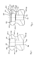
- Fig. 2 shows a rail 110, more precisely a profile rail 130, as for example in connection with the linear guide 100 from Fig. 1 can be used.
- Fig. 2 shows this in cross section in the region of an opening 170.
- the opening 170 is designed as a through hole and has in the region of the surface 160 a chamfer 220.
- the opening 170 has - apart from the chamfer 220 - further on the surface 160 a countersink 230, which is designed in terms of their design so that it can accommodate a screw head.
- another section 240 is separated by a further chamfer 250.
- the opening 170 exits the rail 110 on an opposite side of the surface 160 via an additional chamfer 260.
- the further section 240 is designed with regard to its configuration, in particular its length, along an extension direction 270 of the opening 170 and its diameter to the previously mentioned screw for fastening the rail 110.
- the rail 110 is thus provided for attachment to a corresponding, executed as a bore opening 170 with the counterbore 230 for a countersunk screw and the chamfer 220.
- the screw holes may have, for example, a diameter tolerance of class H12, but possibly also other tolerance classes. However, further special requirements are often not placed on the corresponding design of the openings 170.
- Fig. 3 shows a cross-sectional view of another rail 110, which is based on the cross-sectional view of the rail 110 Fig. 2 essentially with respect to the configuration of the opening 170 in the region of the surface 160 differs.
- a side wall 290 of the opening 170 therefore has a first portion 300, which is given by the further depression 280 substantially.
- a second portion 310 of the sidewall 290 is formed by the counterbore 230.
- the first and second sections 300, 310 thus each have a contour perpendicular to the extension direction 270, wherein the contour of the second section 310 lies completely within or within that of the first section 300.
- a contour is given by a projection of a circumferential line in a cross-sectional plane of the relevant object, that is to say in the present case of the relevant sections 300, 310 of the side wall 290.
- the direction of projection is essentially this parallel to the direction indicated, while the cross-sectional plane in this case is substantially perpendicular to the direction indicated, that is in the present case perpendicular to the extension direction 270 of the opening 170.
- a cap 180 can therefore be used, for example, in connection with the in Fig. 2 shown standard rail with the chamfer 220 are used.
- the further reduction 280 which forms the first portion of the side wall 290.
- a reworking of the openings 170 may be associated with higher costs and a higher degree of inaccuracy, as if the rail 110 is already provided in the context of their production with the corresponding further reduction 280. Regardless, however, it may nevertheless be advisable to use a rail 110 as shown in FIG Fig. 3 is shown by reworking a rail 110, as shown in FIG Fig. 2 is shown to produce, for example, if a stocking can be problematic. Of course, it is also possible to implement the corresponding opening 170 already during the production of the rail 110.
- the use of the rail 110 Fig. 2 may not result in an ideal closing of the rail 110.
- the use of this rail 110 due to its chamfer 220, the possibility that the cap 180 may not complete the rail 110 completely flush. It may thus remain an annular recess around the cap, which is caused by the chamfer 220. If necessary, dirt particles, other foreign bodies or corrosive substances (eg cooling liquid) may accumulate in the latter, which may result in damage to the rail 110, the carriage 120 or a component from the surroundings of the carriage 120 or the rail 110.
- a rail 110 in conjunction with a cap 180, in which the further reduction 280 of the rail 110 with its surface 160 forms a sharp edge. If the cover cap 180 also has a corresponding sharp edge in the region of its cover surface 190, a complete flush termination of the rail 110 may be achieved in this way.
- Fig. 4 illustrated by a plan view of a rail 110 in the form of a rail 130, the aforementioned problem of accuracy in the field of further reduction 280.
- Fig. 4 a plan view of the rail 110 with an opening 170
- the in Fig. 3 has shown cross-section.
- This has been generated by subsequent insertion of the further reduction 280.
- the rework of in Fig. 2 shown standard rail 110 results in the present case, that a center 320 of the reduction 230, which forms the second portion 310, and the further portion 240 from a center 330 of the further reduction 280 differs.
- the eccentricity E represents one of the possible problems of coaxiality which can occur during post-processing.
- the additional counterbore 280 can be introduced into the rail 110 at an angle deviating from 90 ° to the surface 160 and thus optionally run obliquely. In this way, if necessary, a sitting of the cap 180 can be adversely affected. But other production-related deviations can occur as well.
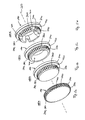
- Fig. 5a to 5d each show perspective views of a cap 180 according to one embodiment.
- cover caps 180 are these in the further course of the description of the embodiments as cover caps 180a ( Fig. 5a ), 180b ( Fig. 5b ), 180c ( Fig. 5c ) and 180d in Fig. 180d ( Fig. 5d ) designated.
- the covers 180 as in the Fig. 5a to 5d are each shown to have a top surface 190 which is formed so that the openings 170 are substantially flush with the surface 160 of the rail 110 can be closed. They are therefore designed in the present case essentially as flat surfaces. However, as will be shown in the following discussion, it may possibly be important in the context of which rail 110 these are used.
- the cover caps 180 further include a first side surface portion 340 aligned parallel to a predetermined direction 350.
- the predetermined direction 350 is here for all in Fig. 5a to 5d shown embodiments of a cap 180 the same. It is in the inserted state substantially coincides with the extension direction 270 of the opening 170.
- the cover caps 180 each have a second side surface portion 360 having a contour perpendicular to the predetermined direction 350 that is recessed from a contour of the first side surface portion 340 along the predetermined direction 350.
- the contour of the second side surface region 360 is thus offset toward an interior of the contour of the first side surface region 340.
- the first side surface region 340 and the second side surface region 360 are embodied as substantially completely rotationally symmetrical, so that the predetermined direction 350 coincides with an axis of symmetry of the respective side surface regions 340, 360.
- the second side surface region 360 has a smaller radial distance from the predetermined direction 350 than the first side surface region 340.
- cover caps 180 a different configuration with corresponding contours may optionally be present.
- the first side surface region 340 and the cover surface 190 immediately adjacent to it may also have a different shape or contour, which, however, substantially corresponds to the contour of the corresponding opening 170 in the rail 110.
- the in the Fig. 5a to 5d shown cover caps 180 further include a third side surface portion 370, which extends at least partially parallel to the predetermined direction 350.
- the third side surface portion 370 is hereby formed so as to form an interference fit with the side wall 290 of the opening 170.
- the first side surface area 340 is formed to form a transitional fit or clearance with the side wall 290.
- chip formation in the region of the first side surface region 340 may possibly be avoided, so that only when inserting the cap 180 into the opening 170 in the region of the third side surface region 370, a corresponding particle, ie, for example, a metal chip, is formed. This can then be taken up in the collecting space formed at least partially by the retracted contour of the second side surface region 360 and remain there.
- the catchment space is determined not least by the height of the second side surface region 360 along the predetermined direction 350.
- the covering cap 180 is as compact as possible and that the particle size of the resulting particles is typically rather small when the covering caps 180 are inserted into the openings 170, it is often possible to limit the height to a maximum of 5 mm. If necessary, it may even be possible to further restrict the height of the second side surface area, for example to not more than 2 mm, not more than 1 mm, not more than 0.5 mm, not more than 0.2 mm or not more than 0.1 mm.
- the second side surface region 360 may be formed, for example, in the form of an undercut and / or a recess.
- cover caps 180 further have toothing structures 380, which are formed as part of the third side surface portions 370.
- the toothing structures 380 are executed in the embodiments shown here as knurling 390, more precisely as axially aligned knurling.
- knurling 390 more precisely as axially aligned knurling.
- other knurls may be used if desired. This may make it possible for the Cover cap 180 just softer in the edge region, so that this can easily adapt to possibly produced with a larger tolerance openings 170 in the rail 110.
- a requirement for the accuracy of the opening 170 and its manufacture may be reduced.
- the diameter of the relevant reduction so for example, the further reduction 280
- the further reduction 280 should be made with high accuracy to a problem-free insertion of the cap 180 enable.
- the previously described toothing structure 380 for example the knurling 390, can be provided in the third side surface area 370. Due to the knurled lateral surface on the cap so possibly tolerances of the production of the reduction can be reduced.
- the cap 180 In the manufacture of the cap 180 according to an embodiment comparatively simple manufacturing methods, such as knurling, can be used, which make it possible to meet the requirements described above.
- the knurling here represents a simple and thus cost-effective form of production of the toothed structure 380. It is used, for example, in the manufacture of handles and gripping surfaces, for example for micrometers, but also to improve a shaft-hub connection, so as to increase the transmittable torque between the shaft and components attached to the shaft.
- the cover caps 180, in which the tooth structure 380 has been produced by knurling, are therefore also referred to as knurled cover caps.
- other manufacturing methods for producing the spline structure 380 may be used.
- the toothing structures 380 do not represent a compelling embodiment in embodiments.
- a tooth structure 380 on the third side surface area 370 may also be omitted.
- the toothing structures 380 that is, for example, the knurls 390, has shown in the context of trial assemblies that the problem of loosening of particles, so for example of chips, in the insertion or pressing of the cap 180 was reinforced.
- the particles typically accumulate on the surface 160 of the rail 110 and, if appropriate, can be pressed flat by the auxiliary tool required for pressing in. If necessary, these particles not only degrade the quality of the flush of the respective surfaces with respect to one another, they may also have to be subsequently eliminated in the course of an additional operation in order to avoid damage to the carriage 120 when the particles in question are run over.
- Embodiments of a cap 180 are now based on the idea of using the existing depression in the rail 110 as the press-fit surface, and by the recessed contour of the second side surface region 360 at least partially a collecting space for the often unavoidable particle or chip formation below the substantially provide flush closing cap. This can optionally be avoided that chips and other particles reach the rail surface 160. As the following description of the embodiments, in particular the Fig. 6 to 13 , will still show, indicate results on sample parts that this can be achieved.
- the contours - apart from the tooth structure 380 - the first side surface portion 340 and the third side surface portion 370 substantially coincide, is in the in the Fig. 5b to 5d
- the covers 180b to 180d reposition the contour perpendicular to the predetermined direction 350 of the third side surface portion 370 from the contour of the first side surface portion 340.
- the contours of the respective first and third side surface regions 340, 370 are substantially in shape identical. More specifically, in the present case, they are even substantially circular except for the optional spline structure 380. In this way, the generation of the particles, that is, for example, the metal shavings during the pressing of the cover 180 in the openings 170 can be specifically displaced deeper into the interior of the rail 110.
- Fig. 5c shown embodiment of the cap 180c a recess 400, which extends from a top surface 190 side facing away into the cap 180c at least partially into an area which is bounded laterally by the third side surface region 370. More specifically, the recess 400 extends at the cap 180c Fig. 5c completely through the above range.
- a flexibility of the cap 180 in this area may optionally be further increased, so that even larger variations in the Koaxialitätsgenautechnik can be forgiven.
- the covering cap 180c can thus be made slightly more robust and, if appropriate, can compensate for greater inaccuracies, for example diameter fluctuations and other coaxiality problems, by the recess 400 described above, without these becoming noticeable on the surface 160 of the rail 110 after the covering caps have been pressed in.
- cap 180c so represents a hollow version of the same, in which more elasticity by the provision of the recess 400 and thus a greater tolerance compensation can be possible.
- the third side surface portion 370 is executed segmented.
- the third side surface region 370 has a plurality of further recesses 410, which are in contact with the recess 400 and thus lead to the described segments of the third side surface region 370.
- the further recesses 410 may thus have a slot shape, for example, so that the third side surface area 370 can be made slotted.
- the third side surface portion 370 of the cap 180d comprises a total of four segments which extend over an angular range of slightly less than 90 ° each.
- the segmentation of the third side surface area 370 may also be performed differently in terms of shape, number of segments, and their configuration.
- an even greater tolerance compensation may possibly be possible as a result.
- the third side surface region 370 extends at least in sections, if not completely parallel to the predetermined direction 350.
- the cover caps 180a to 180d thus each have a chamfer 420 in the region of the third side surface region 370, which is arranged on an end of the cover cap 180 facing away from the cover surface 190 and thus facilitates insertion of the cover cap 180 into the opening 170.
- the chamfers 420 may also be omitted.
- cover caps 180 can be made according to an embodiment of any material that holds the relevant conditions of use. However, as the discussion has previously shown, it may be helpful to fabricate the cover 180 from a corresponding material having such resilience that the cover with the third side surface region may be an interference fit with the side wall 290 of the opening.
- the cap may be made of a metallic material, such as brass or steel, which is why they are sometimes referred to as metal caps. However, it can also be made of other elastic metals or materials. Also, such a cap 180 also be made in one piece, for example, to simplify the production.
- a cap 180 according to an exemplary embodiment can thus enable a robust, cost-effective and at the same time reliable attachment in the openings 170 of a rail, that is, for example, a corresponding screw bore thereof. Due to the configuration of the cover caps 180, it may possibly be possible that when the cover caps 180 are pressed in, as far as possible, no particles, for example metal chips, reach the surface 160 of the rail 110. Thus, the particles can be accommodated in the catchment space and thus kept away from the surface 160. The particles can thus, for example, when moving the corresponding carriage 120 damage its sealing plate 210, which is designed, for example, as a standard seal, or its intent seals, provided that they are provided. Likewise, if necessary, in the case of a design in the form of a profiled rail carriage, they can pass into its rolling element circulation (eg ball circulation) and cause further consequential damage there.
- its rolling element circulation eg ball circulation
- a cap 180 according to an embodiment can be made so often without increased demands on the manufacturing accuracy of the cap itself and the openings 170.
- the use of the toothing structure 380 makes it possible to compensate for manufacturing fluctuations that may occur during the production of the opening 170 and its counterbores (for example, the additional countersink 280) in the rail 110.
- post-processing of the rail 110 ie, for example, cleaning of the rail surface 160
- post-processing of the rail 110 may be omitted after the cap 180 has been pressed in, if appropriate. Due to the design of the cap 180, chips and other particles produced during pressing in may thus remain below the terminating contour and thus do not reach the rail surface 160.
- the top surface 190 may be made smooth, while - depending on the specific implementation of an embodiment - the side facing away from the top surface 190 has the tooth structure 380 or the recess 400, that is knurled and / or executed hollowed out.
- Cover caps 180 can be used as robust cover caps for mounting holes and other openings 170 on rails 130 and similar rails 110 related linear guides.
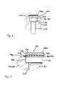
- Fig. 6 shows a cross-sectional view of in Fig. 3 in the opening 170, a screw 430, which is arranged at the level of the second portion 310 and the further portion 240. However, the screw 430 does not extend into the first section 300.
- the cross-sectional view Fig. 6 further shows the cap 180a as shown in FIG Fig. 5a is shown in a position just before or during the depression of the same in the opening 170th Fig. 6 also shows a circle in a Fig. 7 enlarged detail 440.
- Fig. 7 11 shows the first side surface region 340, the second side surface region 360 withdrawn relative to the first side surface region 340, and the third side surface region 370 with the toothed structure 380 attached thereto, which is designed in the form of the knurl 390.
- the third side surface region 370 and the first side surface region 310 have substantially the same diameter here. This agrees approximately with the diameter or the contour of the first portion 300 of the opening 170. For this reason, in the case of the cover cap 180a according to an exemplary embodiment, it can work in conjunction with the rail 110 shown here Fig.
- Fig. 7 schematically a corresponding chip or particle 450th
- cap 180a According to an embodiment at the beginning of the Einpressvons the cap 180 into the opening 170 to form or release the particle 450 come, due to the geometric design of cap 180a and opening 170 in the present case, if necessary Nevertheless, in the area of the surface 160 of the rail 110 may be encountered at the end of the press-fitting.
- FIG. 8 shows the components of Fig. 6 in a pressed-in state, in which the cap 180a closes the opening 170 substantially flush.
- Fig. 9 shows in this context turn the in Fig. 8 drawn section 440 in an enlarged view.
- Fig. 9 illustrates that, in the situations illustrated here, it may happen that the particle 450 (not denoted by a reference numeral in FIG Fig. 9 designated) and the second side surface area 360 formed collecting space 460 on the surface 160 of the rail 110 may arise.
- the particle 450 not denoted by a reference numeral in FIG Fig. 9 designated
- the second side surface area 360 formed collecting space 460 on the surface 160 of the rail 110 may arise.
- chips and other particles 450 may be produced on the surface 160 of the rail during insertion.
- a rail 110 such as in Fig. 2 can be represented by the provision the chamfer 220 may be prevented in conjunction with the cap 180a if necessary.
- the Fig. 6 to 9 illustrate so that by a possibly unsuccessful combination of cap 180 and rail 110 also a particle formation can take place such that the respective particles can still reach the surface. So will the in Fig. 5a shown cap with the in Fig. 2 combined, the location of particle formation through the chamfer 220 is moved down into the rail 110. In such a case, the trap 460 may prevent a forming chip from entering the surface with a significantly greater probability.
- this variant may not be equally suitable for all application scenarios.
- a small annular recess remains in the region of the surface 160 in which impurities or other media can settle and accumulate. These can be whirled up when passing over the recess by the carriage 120, where appropriate, and reach the interior of the carriage 120. If necessary, they can cause damage there. Also, if necessary, a liquid medium can accumulate in the recess, which could damage the carriage 120 or the rail 110. This can be the case, for example, with corrosive media (eg coolant).
- the combination of the cap 180a with the in Fig. 2 rail 110 shown may still allow for horizontal installation on a floor protection of the located in the opening 170 components and structures. If, for example, risks due to contamination or contamination by corrosive media are low, the described combination can also be very helpful when installed horizontally on a floor. If, in contrast, the rail 110 is installed tilted in relation to the horizontal or "overhead", this combination can also be used, if appropriate, under appropriately loaded conditions of use.
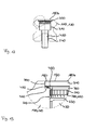
- Fig. 10 shows one Fig. 6 comparable cross-sectional view through the rail 110, as in Fig. 3 is shown, in turn, the screw 430 is arranged such that this through the second portion 310 and the further portion 240 of the opening 170th extends through. Again, the screw 430 is not disposed in the first section 300.
- the cap 180b Fig. 5b used. This has - as explained above - a third side surface area 370 with a recessed relative to the first side surface area 340 contour. As a result, the chip formation or particle formation is shifted further into the interior of the rail 110. To illustrate this in more detail, shows Fig. 11 an enlarged view of the in Fig. 10 marked cutout 440.
- Fig. 11 thus shows the enlarged cutout 440 Fig. 10
- the situation presented here essentially corresponds to that in the 6 and 7 shown situation in which the beginning of the Einpressvons the cap 180 b is shown.
- the cap 180b is seated at an edge between the first portion 300 and the second portion 310 of the opening 170. Therefore, at this edge of the particle 450, that is, the chip, is generated using this cap 180b.
- the location of the press-fitting of the cap 180b is therefore displaced into the counterbore 230 along with the location of the formation of the particle 450.
- Fig. 12 shows one Fig. 10 corresponding representation of the rail 110, the cap 180b and the screw 430 in a fully pressed state.
- the opening 170 (not as such in the FIGS. 12 and 13 is in this case completely flush closed by the cap 180 b, so that the top surface 190 of the cap 180 and the surface 160 of the rail 110 are aligned.
- Fig. 13 again shows an enlarged view of the section 440, as in Fig. 12 is shown.
- Fig. 13 shows an enlarged view of the cutout 440 in the closed state. So shows Fig. 13 on the one hand, that the surface 160 of the rail 110 and the top surface 190 of the cap 180 are aligned with each other. In addition, shows Fig. 13 however, as well, that the particle 450 formed during press-fitting is below in the sump 460 the surface 160 of the rail 110 is trapped.
- the collecting space 460 is here in the region of the transition from the first portion 300 and the second portion 310 of the opening 170 (not designated as such in FIG Fig. 13 ) and formed by the recessed contour of the second side surface area 360.
- chips and other particles 450 generated during the pressing are covered by the cap 180b.
- corresponding images show chips and other particles 450 on a protrusion 470 that forms through the different diameters of the first portion 300 and the second portion 310 of the opening 170.
- chips and other particles that arise during the pressing process which are also referred to as a hole level projection 470.
- the cap 180b and the rail 110 in the region of the opening 170 for example, correspondingly sharp edges having a substantially same contour, so that a substantially completely flush closure of the opening 170 is possible.
- cover cap 180 By means of an exemplary embodiment of a cover cap 180, it may thus be possible to provide an easy-to-manufacture, robust, reliable and as easy as possible to be mounted cover for an opening 170 in a rail 110 of a linear guide 100.
Landscapes
- Engineering & Computer Science (AREA)
- General Engineering & Computer Science (AREA)
- Mechanical Engineering (AREA)
- Bearings For Parts Moving Linearly (AREA)
Applications Claiming Priority (2)
| Application Number | Priority Date | Filing Date | Title |
|---|---|---|---|
| DE202012101435U DE202012101435U1 (de) | 2012-04-18 | 2012-04-18 | Abdeckkappe und Zusammenstellungsprodukt |
| DE201210206374 DE102012206374A1 (de) | 2012-04-18 | 2012-04-18 | Abdeckkappe und Zusammenstellungsprodukt |
Publications (2)
| Publication Number | Publication Date |
|---|---|
| EP2653738A2 true EP2653738A2 (fr) | 2013-10-23 |
| EP2653738A3 EP2653738A3 (fr) | 2015-02-11 |
Family
ID=48190112
Family Applications (1)
| Application Number | Title | Priority Date | Filing Date |
|---|---|---|---|
| EP13164338.9A Ceased EP2653738A3 (fr) | 2012-04-18 | 2013-04-18 | Capuchon |
Country Status (1)
| Country | Link |
|---|---|
| EP (1) | EP2653738A3 (fr) |
Cited By (1)
| Publication number | Priority date | Publication date | Assignee | Title |
|---|---|---|---|---|
| EP4317725A4 (fr) * | 2021-03-29 | 2024-10-16 | NSK Ltd. | Dispositif de guidage de déplacement linéaire |
Citations (8)
| Publication number | Priority date | Publication date | Assignee | Title |
|---|---|---|---|---|
| US2586033A (en) * | 1950-08-29 | 1952-02-19 | American Viscose Corp | Metallically sheathed bucket rim |
| US2701659A (en) * | 1951-06-26 | 1955-02-08 | Seismograph Service Corp | Locking and sealing arrangement |
| DE9408850U1 (de) * | 1993-06-28 | 1994-09-08 | Star Gmbh | Linearbewegungsführung |
| DE20311173U1 (de) * | 2003-07-19 | 2003-10-16 | THK GmbH, 40878 Ratingen | Vorrichtung zum Verschließen einer Längsnut und/oder von Bohrungen bzw. Einsenkungen auf der Oberfläche einer Führungsschiene |
| US20050115732A1 (en) * | 2003-11-29 | 2005-06-02 | Tu Ying L. | Screw cap for a portable electronic device |
| US20090010577A1 (en) * | 2005-02-01 | 2009-01-08 | Thk Co., Ltd. | Structure for Closing a Rail Mounting Hole |
| US20100183252A1 (en) * | 2009-01-19 | 2010-07-22 | Ming-Yao Lin | Component for Linear Guideway and Method for making the same |
| JP2010190317A (ja) * | 2009-02-18 | 2010-09-02 | Nsk Ltd | リニアガイド装置のキャップ |
Family Cites Families (3)
| Publication number | Priority date | Publication date | Assignee | Title |
|---|---|---|---|---|
| JPH087138Y2 (ja) * | 1991-04-05 | 1996-03-04 | 日本精工株式会社 | リニアガイド装置のレール取付穴用キャップ |
| JP2007113671A (ja) * | 2005-10-20 | 2007-05-10 | Nsk Ltd | 直動案内軸受装置及びレールキャップ |
| US20100040314A1 (en) * | 2008-08-17 | 2010-02-18 | Ming-Yao Lin | Linear Guideway |
-
2013
- 2013-04-18 EP EP13164338.9A patent/EP2653738A3/fr not_active Ceased
Patent Citations (8)
| Publication number | Priority date | Publication date | Assignee | Title |
|---|---|---|---|---|
| US2586033A (en) * | 1950-08-29 | 1952-02-19 | American Viscose Corp | Metallically sheathed bucket rim |
| US2701659A (en) * | 1951-06-26 | 1955-02-08 | Seismograph Service Corp | Locking and sealing arrangement |
| DE9408850U1 (de) * | 1993-06-28 | 1994-09-08 | Star Gmbh | Linearbewegungsführung |
| DE20311173U1 (de) * | 2003-07-19 | 2003-10-16 | THK GmbH, 40878 Ratingen | Vorrichtung zum Verschließen einer Längsnut und/oder von Bohrungen bzw. Einsenkungen auf der Oberfläche einer Führungsschiene |
| US20050115732A1 (en) * | 2003-11-29 | 2005-06-02 | Tu Ying L. | Screw cap for a portable electronic device |
| US20090010577A1 (en) * | 2005-02-01 | 2009-01-08 | Thk Co., Ltd. | Structure for Closing a Rail Mounting Hole |
| US20100183252A1 (en) * | 2009-01-19 | 2010-07-22 | Ming-Yao Lin | Component for Linear Guideway and Method for making the same |
| JP2010190317A (ja) * | 2009-02-18 | 2010-09-02 | Nsk Ltd | リニアガイド装置のキャップ |
Cited By (1)
| Publication number | Priority date | Publication date | Assignee | Title |
|---|---|---|---|---|
| EP4317725A4 (fr) * | 2021-03-29 | 2024-10-16 | NSK Ltd. | Dispositif de guidage de déplacement linéaire |
Also Published As
| Publication number | Publication date |
|---|---|
| EP2653738A3 (fr) | 2015-02-11 |
Similar Documents
| Publication | Publication Date | Title |
|---|---|---|
| DE102008029236B3 (de) | Verbindungselement mit einer Schraube und einer daran unverlierbar angeordneten Hülse | |
| DE102007047860B3 (de) | Verbindungselement mit einer Schraube und einer daran unverlierbar angeordneten Hülse | |
| DE112010002968T5 (de) | Kurvenrolle und Verfahren zum Herstellen der Kurvenrolle | |
| DE112016006596T5 (de) | Hydraulikzylinder | |
| DE4401622C2 (de) | Befestigungsvorrichtung für ein Montageglied einer Mutter-Schraube-Verbindung | |
| DE102013011469A1 (de) | Führungseinrichtung für eine Schwimmsattel-Scheibenbremse | |
| DE112005003442B4 (de) | Aufbau zum Schließen eines Schienenmontagelochs | |
| DE102013214245A1 (de) | Geteilter Wälzkörperkäfig | |
| DE202012101435U1 (de) | Abdeckkappe und Zusammenstellungsprodukt | |
| EP2653738A2 (fr) | Capuchon | |
| WO2018196916A1 (fr) | Mécanisme de vis-écrou à billes | |
| DE102013224459A1 (de) | Verbindungseinrichtung umfassend eine Abstandsbuchse und eine Schraube | |
| DE102012206374A1 (de) | Abdeckkappe und Zusammenstellungsprodukt | |
| EP4023894B1 (fr) | Élément fonctionnel, composant d'assemblage et procédé de fabrication d'un composant d'assemblage | |
| EP1039158B1 (fr) | Palier linéaire à éléments roulants | |
| DE102014219729B4 (de) | Verfahren zur Herstellung eines Wälzkörperkäfigs und Wälzkörperkäfig | |
| DE112014004081B4 (de) | Bewegungsführungseinrichtung | |
| EP2978564B1 (fr) | Cage de serrage pourvue d'éléments de fixation | |
| EP3599388B1 (fr) | Dispositif de chargement | |
| DE102016223233A1 (de) | Wälzkörpergewindetrieb mit radial eingesetzten, einstückigen Umlenkelementen | |
| EP2599644B1 (fr) | Composant de roulettes avec installation de stockage pouvant être bloquée | |
| DE202011108509U1 (de) | Kugelrollen-Bauteil mit rastbarer Lagereinrichtung | |
| DE102011080054A1 (de) | Injektionskopf und Auswerfer einer Injektionsvorrichtung | |
| DE112023001916T5 (de) | Montagelochabdeckung und Bewegungsführungsvorrichtung | |
| DE102008027510A1 (de) | Befestigungsvorrichtung für einen Fensterheberantrieb |
Legal Events
| Date | Code | Title | Description |
|---|---|---|---|
| PUAI | Public reference made under article 153(3) epc to a published international application that has entered the european phase |
Free format text: ORIGINAL CODE: 0009012 |
|
| AK | Designated contracting states |
Kind code of ref document: A2 Designated state(s): AL AT BE BG CH CY CZ DE DK EE ES FI FR GB GR HR HU IE IS IT LI LT LU LV MC MK MT NL NO PL PT RO RS SE SI SK SM TR |
|
| AX | Request for extension of the european patent |
Extension state: BA ME |
|
| PUAL | Search report despatched |
Free format text: ORIGINAL CODE: 0009013 |
|
| AK | Designated contracting states |
Kind code of ref document: A3 Designated state(s): AL AT BE BG CH CY CZ DE DK EE ES FI FR GB GR HR HU IE IS IT LI LT LU LV MC MK MT NL NO PL PT RO RS SE SI SK SM TR |
|
| AX | Request for extension of the european patent |
Extension state: BA ME |
|
| RIC1 | Information provided on ipc code assigned before grant |
Ipc: F16C 29/08 20060101AFI20150105BHEP Ipc: F16C 29/00 20060101ALI20150105BHEP |
|
| 17P | Request for examination filed |
Effective date: 20150810 |
|
| RBV | Designated contracting states (corrected) |
Designated state(s): AL AT BE BG CH CY CZ DE DK EE ES FI FR GB GR HR HU IE IS IT LI LT LU LV MC MK MT NL NO PL PT RO RS SE SI SK SM TR |
|
| 17Q | First examination report despatched |
Effective date: 20160902 |
|
| STAA | Information on the status of an ep patent application or granted ep patent |
Free format text: STATUS: EXAMINATION IS IN PROGRESS |
|
| STAA | Information on the status of an ep patent application or granted ep patent |
Free format text: STATUS: THE APPLICATION HAS BEEN REFUSED |
|
| 18R | Application refused |
Effective date: 20191103 |