EP2653789A2 - Method and system for tempering components - Google Patents
Method and system for tempering components Download PDFInfo
- Publication number
- EP2653789A2 EP2653789A2 EP13156578.0A EP13156578A EP2653789A2 EP 2653789 A2 EP2653789 A2 EP 2653789A2 EP 13156578 A EP13156578 A EP 13156578A EP 2653789 A2 EP2653789 A2 EP 2653789A2
- Authority
- EP
- European Patent Office
- Prior art keywords
- temperature
- tempering
- return
- flow
- controller
- Prior art date
- Legal status (The legal status is an assumption and is not a legal conclusion. Google has not performed a legal analysis and makes no representation as to the accuracy of the status listed.)
- Granted
Links
Images

Classifications
-
- F—MECHANICAL ENGINEERING; LIGHTING; HEATING; WEAPONS; BLASTING
- F24—HEATING; RANGES; VENTILATING
- F24F—AIR-CONDITIONING; AIR-HUMIDIFICATION; VENTILATION; USE OF AIR CURRENTS FOR SCREENING
- F24F11/00—Control or safety arrangements
- F24F11/70—Control systems characterised by their outputs; Constructional details thereof
- F24F11/80—Control systems characterised by their outputs; Constructional details thereof for controlling the temperature of the supplied air
- F24F11/83—Control systems characterised by their outputs; Constructional details thereof for controlling the temperature of the supplied air by controlling the supply of heat-exchange fluids to heat-exchangers
- F24F11/84—Control systems characterised by their outputs; Constructional details thereof for controlling the temperature of the supplied air by controlling the supply of heat-exchange fluids to heat-exchangers using valves
-
- F—MECHANICAL ENGINEERING; LIGHTING; HEATING; WEAPONS; BLASTING
- F24—HEATING; RANGES; VENTILATING
- F24F—AIR-CONDITIONING; AIR-HUMIDIFICATION; VENTILATION; USE OF AIR CURRENTS FOR SCREENING
- F24F11/00—Control or safety arrangements
- F24F11/70—Control systems characterised by their outputs; Constructional details thereof
- F24F11/72—Control systems characterised by their outputs; Constructional details thereof for controlling the supply of treated air, e.g. its pressure
-
- F—MECHANICAL ENGINEERING; LIGHTING; HEATING; WEAPONS; BLASTING
- F24—HEATING; RANGES; VENTILATING
- F24F—AIR-CONDITIONING; AIR-HUMIDIFICATION; VENTILATION; USE OF AIR CURRENTS FOR SCREENING
- F24F3/00—Air-conditioning systems in which conditioned primary air is supplied from one or more central stations to distributing units in the rooms or spaces where it may receive secondary treatment; Apparatus specially designed for such systems
- F24F3/06—Air-conditioning systems in which conditioned primary air is supplied from one or more central stations to distributing units in the rooms or spaces where it may receive secondary treatment; Apparatus specially designed for such systems characterised by the arrangements for the supply of heat-exchange fluid for the subsequent treatment of primary air in the room units
-
- F—MECHANICAL ENGINEERING; LIGHTING; HEATING; WEAPONS; BLASTING
- F24—HEATING; RANGES; VENTILATING
- F24F—AIR-CONDITIONING; AIR-HUMIDIFICATION; VENTILATION; USE OF AIR CURRENTS FOR SCREENING
- F24F5/00—Air-conditioning systems or apparatus not covered by F24F1/00 or F24F3/00, e.g. using solar heat or combined with household units such as an oven or water heater
- F24F5/0089—Systems using radiation from walls or panels
- F24F5/0092—Systems using radiation from walls or panels ceilings, e.g. cool ceilings
-
- G—PHYSICS
- G05—CONTROLLING; REGULATING
- G05D—SYSTEMS FOR CONTROLLING OR REGULATING NON-ELECTRIC VARIABLES
- G05D23/00—Control of temperature
- G05D23/01—Control of temperature without auxiliary power
- G05D23/02—Control of temperature without auxiliary power with sensing element expanding and contracting in response to changes of temperature
- G05D23/08—Control of temperature without auxiliary power with sensing element expanding and contracting in response to changes of temperature with bimetallic element
-
- G—PHYSICS
- G05—CONTROLLING; REGULATING
- G05D—SYSTEMS FOR CONTROLLING OR REGULATING NON-ELECTRIC VARIABLES
- G05D23/00—Control of temperature
- G05D23/19—Control of temperature characterised by the use of electric means
- G05D23/1927—Control of temperature characterised by the use of electric means using a plurality of sensors
- G05D23/193—Control of temperature characterised by the use of electric means using a plurality of sensors sensing the temperaure in different places in thermal relationship with one or more spaces
- G05D23/1931—Control of temperature characterised by the use of electric means using a plurality of sensors sensing the temperaure in different places in thermal relationship with one or more spaces to control the temperature of one space
-
- F—MECHANICAL ENGINEERING; LIGHTING; HEATING; WEAPONS; BLASTING
- F24—HEATING; RANGES; VENTILATING
- F24D—DOMESTIC- OR SPACE-HEATING SYSTEMS, e.g. CENTRAL HEATING SYSTEMS; DOMESTIC HOT-WATER SUPPLY SYSTEMS; ELEMENTS OR COMPONENTS THEREFOR
- F24D2220/00—Components of central heating installations excluding heat sources
- F24D2220/02—Fluid distribution means
- F24D2220/0264—Hydraulic balancing valves
-
- F—MECHANICAL ENGINEERING; LIGHTING; HEATING; WEAPONS; BLASTING
- F24—HEATING; RANGES; VENTILATING
- F24D—DOMESTIC- OR SPACE-HEATING SYSTEMS, e.g. CENTRAL HEATING SYSTEMS; DOMESTIC HOT-WATER SUPPLY SYSTEMS; ELEMENTS OR COMPONENTS THEREFOR
- F24D3/00—Hot-water central heating systems
- F24D3/12—Tube and panel arrangements for ceiling, wall, or underfloor heating
- F24D3/14—Tube and panel arrangements for ceiling, wall, or underfloor heating incorporated in a ceiling, wall or floor
-
- Y—GENERAL TAGGING OF NEW TECHNOLOGICAL DEVELOPMENTS; GENERAL TAGGING OF CROSS-SECTIONAL TECHNOLOGIES SPANNING OVER SEVERAL SECTIONS OF THE IPC; TECHNICAL SUBJECTS COVERED BY FORMER USPC CROSS-REFERENCE ART COLLECTIONS [XRACs] AND DIGESTS
- Y02—TECHNOLOGIES OR APPLICATIONS FOR MITIGATION OR ADAPTATION AGAINST CLIMATE CHANGE
- Y02B—CLIMATE CHANGE MITIGATION TECHNOLOGIES RELATED TO BUILDINGS, e.g. HOUSING, HOUSE APPLIANCES OR RELATED END-USER APPLICATIONS
- Y02B30/00—Energy efficient heating, ventilation or air conditioning [HVAC]
Definitions
- the invention relates to a tempering for tempering, ie for heating or cooling of a component.
- a tempering for tempering ie for heating or cooling of a component.
- Such components are e.g. a floor, wall or ceiling of a living or working room; but it can also be isolated heating or cooling walls.
- a temperature control system suitable for carrying out this tempering process typically comprises a temperature control device, a temperature control arrangement, a feed line and a return line, which are all connected to one another.
- This temperature control system also includes a control and regulation unit with an actuator, a flow temperature sensor and a return temperature sensor.
- the adjustment of the flow of the tempering fluid is usually carried out statically by means of mechanical flow actuators.
- the thermal actuators are designed as a two-step control and the energy to be delivered, for example, designed as a heating system temperature control is essentially adjusted by a complex hydraulic balancing the TOP meter.
- the installer requires parameters for setting the flow to be achieved.
- the parameters are influenced by the pipe diameter (silting up) and the flow pressure (eg by opening and closing several parallel strands) of the tempering fluid.
- the resulting flow and return temperature is further influenced by the flow temperature and the temperature of the temperature control.
- the flow temperature and the temperature of the temperature control Despite experience and application of the greatest care, however, only an inaccurate setting of the individual strands or heating circuits is possible. This results in an uneven heat distribution on the one hand, or an insufficient energy efficiency on the other.
- Next are in conversions the theoretical determined control variables not available and can only be determined with great effort.
- Another problem is inaccurate room thermostats that often perform a simple on / off function on such a floor heating.
- a flow temperature of the tempering fluid and with the return temperature sensor a return temperature of the tempering fluid is detected with the flow temperature sensor.
- a temperature difference between the flow temperature and the return temperature of the tempering fluid is detected with a controller of the controller, wherein the controller causes from this temperature difference, the actuator of the valve for adjusting the opening degree of the valve, that the average temperature difference between the flow temperature and the return temperature of the Tempering fluid is in a predetermined range of values.
- the controller detects the respective temperature differences between the common, detected by the flow temperature sensor flow temperature and the 2 to n individual detected by the return temperature sensor return temperatures of the tempering. In this case, an individual temperature difference between the flow temperature and one of the 2 to n return temperatures of the tempering fluid is detected by the controller of the controller. Based on these individual temperature differences, the controller causes the actuators of the 2 to n valves to adjust the opening degree of these valves such that the individual average temperature differences between the flow temperature and the respective return temperature of the tempering fluid are each in a predetermined range of values.
- the controller comprises a regulator which is designed to detect a temperature difference between the flow temperature and the return temperature of the temperature control fluid.
- the controller is designed such that, starting from this temperature difference, it causes the actuator of the valve to adjust the opening degree of the valve such that the mean temperature difference between the flow temperature and the return temperature of the temperature control fluid is in a predetermined range of values.
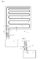
- FIG. 1 shows a schematic plan view of a simpler tempering according to a first embodiment.
- This tempering system is suitable for carrying out the method according to the invention for controlling the temperature of a component.
- This simpler tempering system 1 for carrying out the tempering method according to the invention comprises a tempering device 3 designed for heating or cooling a tempering fluid 2.
- This simpler tempering system 1 additionally comprises a tempering arrangement 5 (in the exemplary form of an embodiment shown in FIG. 1) for passing the tempering fluid 2 through a component 4 to be tempered the component 4 threaded, meandering pipe).
- This simpler tempering 1 also comprises a flow line 6, via which the temperature control 3 is connected to the temperature control 5 for supplying the tempering 2, and a return line 7 through which the temperature control 5 is connected to the temperature control 3 for returning the tempering.
- This simpler tempering 1 also includes a controller 8.
- This control 8 comprises a valve 9 with an actuator 10, this actuator 10 is designed to set an opening degree of the valve 9 used in the flow line 6 or in the return line 7 of the simpler temperature control system 1.
- the controller 8 includes a flow temperature sensor 11 and a return temperature sensor 12. This controller 8 is configured to drive the actuator 10.
- the flow temperature sensor 11 is designed to detect a flow temperature of the tempering 2 and the return temperature sensor 12 is for detecting a return temperature of the tempering 2.
- the controller 8 of the inventive simpler tempering 1 further comprises a controller 13 which is designed to detect a temperature difference between the flow temperature and the return temperature of the tempering 2. In this case, the controller 13 is designed so that it causes starting from this temperature difference, the actuator 10 of the valve 9 for adjusting the opening degree of the valve 9, that the average temperature difference between the flow temperature and the return temperature of the tempering 2 is in a predetermined range of values.
- a flow temperature of the tempering fluid 2 and, with the return temperature sensor 12, a return temperature of the tempering fluid 2 are detected by the flow temperature sensor 11.
- a regulator 13 which is encompassed by the controller 8
- a temperature difference between the flow temperature and the return temperature of the tempering fluid (2) is detected.
- the actuator 10 of the valve 9 such for adjusting the opening degree of this valve 9, that the average temperature difference between the flow temperature and the return temperature of the tempering 2 is in a predetermined range of values.
- the flow temperature of the tempering 2 is preferably in the flow line 6 and the return temperature of the tempering 2 is preferably detected in the return line 7.
- both temperature sensors 11, 12 are located outside of the component 4 (ie at the "beginning" or “end” of the temperature control arrangement 5) and are thus accessible at any time, for example, for maintenance work.
- the temperature difference between the flow temperature and the return temperature can be constant (cf. Fig. 5 ) or variable, for example, oscillating (see. Fig. 6 ) and accept different values. In order to correspond to these different operating states, it is therefore spoken of a mean temperature difference.
- the predetermined value range for this average temperature difference preferably comprises less than 20 ° C and is preferably 1 to 10 ° C and more preferably 2 to 6 ° C.
- the controller 13 as soon as it determines that the measured flow temperature reaches a predetermined value, causes the actuator 10 to close the valve 9.
- This rule is particularly useful when e.g. When heating a living room floor 4, the controller determines that the flow temperature exceeds the return temperature by too high a value. With this preferably temporary closure of the valve 9, overheating of the living room floor can be prevented. This will e.g. prevents damage to the floor covering (for example parquet).
- a temperature difference between a current room temperature and a selected desired temperature is detected from temperature data recorded and provided with a thermostat 14 of the simpler temperature control system 1, and that in the flow line 6 or In the return line 7 arranged closing valve 24 is opened or closed according to a certain value of this temperature difference.
- This rule is particularly useful when a 2-point control is to be used to set a maximum temperature difference, for example, 2 ° C between the setpoint temperature and the actual temperature (room temperature).
- the controller 13 of the controller 8 and with a room thermometer also an actual temperature of a room in the vicinity of the component 4 is detected, the controller 13, as soon as he determines that the measured flow temperature deviates from the actual temperature by a predetermined range of values, the actuator 10 causes the valve 9 to close.
- This rule is particularly useful if, for example, when heating a living room floor 4, the room temperature rises unexpectedly (eg by sunlight or the operation of a fireplace).
- This range of values can be adapted to the actual conditions, for example 10 ° C, 5 ° C or 2 ° C.
- valve 9 With this preferably temporary closure of the valve 9 can be prevented that the living room floor by a too low flow temperature unintentionally heat is withdrawn. During heating, these value ranges are typically below the actual temperature; During cooling, these ranges of values are typically above the actual temperature.
- Fig. 1 shows a schematic plan view of a simpler temperature control system 1 according to a first embodiment, in which the sensors for the flow temperature 11 and the return temperature 12 are arranged close to the valve 9 used here in the return line 7.
- the actuator 10 with the controller 13 is disposed directly at the valve 9.
- the controller 13 is electrically connected to the flow temperature sensor 11 and the return temperature sensor 12, which is shown here by dotted lines.
- the closure valve 24 is inserted here in the flow line 6.
- the entire controller 8 is outside the component 4 and also outside the tempering device 3rd
- FIG. 2 Comparable to the shows FIG. 2 a schematic partial plan view of the control of a simpler tempering according to a second embodiment, in which the sensors for the flow temperature 11 and the return temperature 12 are arranged close to the valve 9 used here in the flow line 6.
- the actuator 10 is again arranged directly at the valve 9.
- the controller 13 is located at a practically arbitrary distance to the previously mentioned components of the controller 8 and is located in the vicinity of the temperature control device 3 or even integrated into the latter.
- the controller 13 is electrically connected to the flow temperature sensor 11 and to the return temperature sensor 12 and to the actuator 10, which is shown here by dotted lines.
- the closure valve 24 is inserted here in the return line 7.
- the controller 8 is distributed to an area outside the component 4 and to an area at or within the temperature control device 3.
- FIG. 3 shows a schematic plan view of a more complex temperature control 1 'for performing the inventive method for controlling the temperature of components 4, wherein different embodiments are shown.
- This more complex tempering system 1 ' comprises two tempering arrangements 5, 5' (in each case in the exemplary form of pipes laid in the component 4 in a loop-like or meandering manner) for passing the tempering fluid 2 through the component 4 to be tempered.
- the two tempering arrangements 5, 5 ' connected via a common flow line 6 with the temperature control device 3.
- This more complex tempering system 1 ' also comprises two return lines 7, 7' for returning the tempering fluid 2 from the two temperature control arrangements 5, 5 'to the temperature control device 3.
- This more complex tempering system 1 'further comprises two return temperature sensors 12,12', wherein each return temperature sensor 12,12 'on or in one of the return lines 7,7' and the flow temperature sensor 11 is arranged on or in the common flow line 6.
- This complex temperature control system 1 ' also comprises two valves 9,9', each equipped with an actuator 10,10 'and in each case a separate flow line 6', 6 "after a flow distributor bar 23 or in each one of the return lines 7.7
- the actuators 10, 10 ' are designed to set an opening degree of the respective valve 9, 9' and the controller 8 is designed to drive the actuators 10, 10 '.
- this more complex tempering system 1 ' may have two tempering arrangements 5, 5', but it may also be more than two (that is, n ) tempering arrangements.
- the number of return lines 7, 7 ', return temperature sensors 12, 12', valves 9, 9 'and actuators 10, 10' also increases correspondingly to the number of tempering arrangements, so that with all of these components with a more complex temperature control system 1 'with a number from 2 to n can be expected.
- the 2 to n tempering arrangements 5, 5 ' are connected to the temperature control device 3 via a common feed line 6.
- this more complex tempering system 1' can comprise a supply distributor bar 23 or, alternatively, a simple T unit for connecting the common supply conduit 6 to the separate supply conduit 6 ', 6 " a more complex temperature control system 1 'more than two separate flow lines 6', 6 "includes, the expert will typically always provide a flow distributor bar 23. If, as shown, only two tempering arrangements 5, 5 'are present, this more complex tempering system 1' can have two separate return lines 7, 7 '; however, these two return lines 7, 7 'can alternatively be connected to the temperature control device 3 via a return distributor bar 23' or alternatively via a simple T piece and then a common return line. If a more complex temperature control system 1 'has more than two temperature control arrangements 5, 5', the skilled person will typically always provide a return manifold 23 '.
- the 2 to n valves 9, 9 ' which are each equipped with an actuator 10, 10', can each be fitted with a separate supply line 6 ', 6 "(in FIG Fig. 3 dotted drawn and seen in the direction of flow) after a flow distributor bar 23 (bold drawn drawn) or alternatively in each case one of the return lines 7,7 'are used.
- the insertion of the 2 to n valves 9,9 'in each one of the return lines 7,7' is preferably (in the flow direction) in front of a return manifold 23 '(bold dotted line), if such a return manifold 23' is provided is.
- the sensors for the flow temperature 11 and for the return temperature 12,12 'near the flow distributor beam 23 and near the return manifold 23' are arranged.
- the valves 9, 9 ' are arranged with the associated actuators 10, 10' in the vicinity of the return temperature sensors 12, 12 'and before the return distributor bar 23' or alternatively after the supply distributor bar 23.
- Particularly preferred are the temperature sensors 11,12,12 'outside of the component 4 (ie at the "beginning" or "end” of the temperature control assemblies 5,5') and are therefore accessible at any time for example for maintenance.
- the electrical connections between the actuators 10, 10 'and the regulator 13 arranged in the temperature control device 13 are not shown here.
- the controller 13 is also electrically connected to the flow temperature sensor 11 and the return temperature sensors 12,12 ', which is shown here by dotted lines.
- the closure valve 24 is usually inserted into the return line 7.
- the controller 8 is distributed to an area outside of the component 4 and to an area at or within the tempering device 3. In this example, a check valve 24 has been dispensed with.
- the inventive method is carried out with such a complex temperature control 1 'by the controller 13, the respective temperature differences between the common, detected by the flow temperature sensor 11 flow temperature and the two (generally 2 to n ) individual detected by the return temperature sensor 12,12' return temperatures of Temperierfluids 2 detected.
- an individual temperature difference between the flow temperature and one of the two (generally 2 to n ) return temperatures of the tempering fluid 2 is detected by the controller 13 of the control 8.
- the controller 13 Based on these individual temperature differences causes the controller 13, the actuators 10,10 'of the two (generally 2 to n ) valves 9,9' so to adjust the opening degree of these valves 9,9 'that the individual mean temperature differences between the flow temperature and the respective return temperature of the tempering 2 in each case a predetermined range of values.
- the value ranges of the temperature differences and flow rates controlled by the controller 13 are different in the two (generally 2 to n ) temperature control arrangements 5, 5 '.
- the predetermined value ranges of the temperature differences regulated by the controller 13 are 1 ° C to 10 ° C, preferably 2 ° C to 6 ° C.
- a temperature control method became a living space floor with a total surface of 40 m 2 with two Heating circuits, ie equipped with two temperature control arrangements 5,5 'of such a complex temperature control system 1'.
- the first temperature control arrangement 5 supplied a first partial area of 20 m 2 and the second temperature control arrangement 5 'a second partial area of 20 m 2 of the living space floor.
- Both Temperieran für extracten 5,5 ' were connected via a common flow line 6 to a trained for heating temperature control 3, said common feed line 6 a operatively connected to a controller 13 and a controller 8 flow temperature sensor 11 included.
- a check valve 24 has been dispensed with.
- a room temperature sensor was used to measure the room temperature, but this measurement only indicated the effect of the tempering process, but did not affect the tempering process itself.
- the flow of the tempering 2 with open valves 9,9 ' was about 2.5 l / min.
- This example shows that the temperature of a living space can be controlled very precisely with this relatively simple tempering process, despite different outside temperatures.
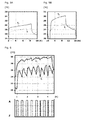
- the FIG. 4 shows a selection of exemplary actuator / controller combinations.
- the Fig. 4A shows a designed as a controller 13 bimetallic actuator 10.
- This bimetallic actuator / regulator 15 is arranged between the flow line 6 and the return line 7, that it contacts the two lines, each with one of the components of the bimetal.
- the contact of the bimetallic actuator / regulator 15 with the flow line 6 and with the return line 7 is so intense that each material component of the bimetallic actuator / regulator 15 assumes either the flow temperature or the return temperature.
- This bimetallic actuator / regulator 15 comprises a lever which is formed from the two components of the bimetal and which presses on a valve part of the valve 9 which is guided in a spring-biased manner by approximately one stroke 16.
- the mean value range of the temperature difference between supply and return temperatures can be adjusted be that it is 1 ° C to 10 ° C and preferably 2 ° C to 6 ° C, and that controlled by this currentless bimetallic actuator / regulator 15 controlled flows in the temperature control assemblies 5,5 '0.2 l / min to 10 l / min amount.
- the Fig. 4B shows an expansion actuator in combination with a regulator which is designed as a Schmitt trigger.
- the Schmitt trigger 17 is electrically connected on the input side to the flow temperature sensor 11 and also to the return temperature sensor 12 or is electrically connected to the expansion actuator 18 on the output side.
- the expansion actuator 18 includes an electric heater and a self-contained actuator cartridge with temperature-dependent volume. Now, if the flow temperature is higher than the return temperature, the Schmitt trigger 17 detects this temperature difference and he causes the electric heater in the expansion actuator 18 to heat the actuator cartridge so that this by a corresponding amount (maximum by the hub 16 ) expands. As a result, the spring-guided valve body of the valve 9 is moved by an amount which corresponds precisely to the temperature difference.
- the valve body brings the valve 9 in an enlarged open position, so that more tempering fluid 2 can circulate through the temperature control 5.
- the mean value range of the temperature difference between flow and return temperatures can be set to be 1 ° C to 10 ° C and preferably 2 ° C to 6 ° C , And that the flow rates in the temperature control assemblies 5.5 '0.2 l / min to 10 l / min.
- the Fig. 4C shows an actuator designed as an electric motor in combination with a differential amplifier.
- the differential amplifier 19 is the input side electrically connected to the flow temperature sensor 11 and also to the return temperature sensor 12 and the output side electrically connected to the electric motor 20 of the actuator, which also includes a spindle. Now, if the flow temperature is higher than the return temperature, the differential amplifier 19 detects this temperature difference and it causes the electric motor 20 in the actuator to drive the spindle so that this by a corresponding amount (maximum by the stroke 16) moves against the valve 9. As a result, the spring-guided valve body of the valve 9 is moved by an amount which corresponds precisely to the temperature difference.
- the valve body brings the valve 9 in an enlarged open position, so that more tempering fluid 2 can circulate through the temperature control 5.
- the mean value range of the temperature difference between flow and return temperatures can be adjusted to be 1 ° C to 10 ° C and preferably 2 ° C to 6 ° C, and that the flow rates in the temperature control arrangements are 5.5 '0.2 l / min to 10 l / min.
- the Fig. 4D shows a solenoid actuator in combination with a microprocessor.
- the microprocessor 21 is the input side electrically connected to the flow temperature sensor 11 and also to the return temperature sensor 12 and the output side electrically connected to the coil of a solenoid actuator 22, which also comprises a core.
- the microprocessor 21 detects this temperature difference and it causes the coil of the solenoid actuator 22 to drive the core so that this by a corresponding amount (maximum of the stroke 16) against the valve. 9 emotional.
- the spring-guided valve body of the valve 9 is moved by an amount which corresponds precisely to the temperature difference.
- the mean value range of the temperature difference between flow and return temperatures can be set to be 1 ° C to 10 ° C, and preferably 2 ° C to 6 ° C, and that the flow rates in the temperature control arrangements are 5.5 '0.2 l / min to 10 l / min.
- the FIG. 5A shows in a temperature / time diagram, the temperature profile of the flow temperature T v and the return temperature T r at a constant flow of the tempering of 2.5 l / min and with a resulting, constant temperature difference between flow temperature and return temperature of about 2.0 ° C.
- the FIG. 5B shows in a temperature / time diagram, the temperature profile of the flow temperature T v and the return temperature T r at a constant flow of the tempering of 0.5 l / min and with a resulting, constant temperature difference between flow temperature and return temperature of about 4.0 ° C.
- the FIG. 6 shows in a temperature / time diagram, the temperature profile of the flow temperature T v and the return temperature T r with a control 8, in which the valve 9 was pulsed opened and closed again.
- the shows Fig. 6 Shown here is a possible control behavior in which the mean spread of the flow temperature T v and the return temperature T r directly with the actuator 10 and with this actuator 10th associated valve 9 is set dynamically.
- the upper curve shows the flow temperature T v , the lower curve, the return temperature T r and the pulse curve, the actuator signal, wherein A is 100% on and Z for 0%.
- the controller 13 sets this value independently of the pressure of the tempering 2, regardless of the flow of the tempering 2, regardless of the flow temperature and regardless of the temperature of the temperature control 3.
- the maximum total temperature difference between the flow temperature and the return temperature is about 6 ° C
- the maximum current temperature difference between the flow temperature and the return temperature is about 5 ° C
- the average resulting temperature difference between the flow temperature and the return temperature is about 4 ° C.
- tempering fluid 2 is understood to be any fluid, gas or gas-liquid mixture which is used for heating (supplying energy) and / or for cooling (discharging energy) and thus also for transporting of energy or heat can be used.
- floor heaters for example, a water-antifreeze mixture may be used, and in refrigeration circuits, a liquid having a high heat of vaporization capacity is often used.
- tempering 3 for example, a pellet, gas or oil burner with a boiler or a cooling unit with a coolant tank in question.
- one or more floors, one or more walls and / or a ceiling or several ceilings of living or working spaces can be considered as the component 4 to be tempered.
- These components can also be present, for example, in storage rooms or showrooms.
- These components can also be designed as a stand-alone, hanging or horizontal heating or cooling walls.
- thermocontrol systems 1,1 As an exemplary fluidic connection in temperature control systems 1,1 'apply here lines for conducting tempering fluids, such as pipes and the like.
- exemplary electrical connections in temperature control systems 1,1 'here are electrical cables for conducting electrical signals but also wireless connections for transmitting electronic data or signals.
- the valves 9,9 'are preferably designed as flow control valves and in the open state preferably always have a minimum opening degree which causes a minimum flow of the tempering fluid 2 of 0.1 to 2 l / min.
- the actuators 10, 10 ' comprise spring-loaded plungers.
Landscapes
- Engineering & Computer Science (AREA)
- Chemical & Material Sciences (AREA)
- Combustion & Propulsion (AREA)
- Mechanical Engineering (AREA)
- General Engineering & Computer Science (AREA)
- Physics & Mathematics (AREA)
- General Physics & Mathematics (AREA)
- Automation & Control Theory (AREA)
- Remote Sensing (AREA)
- Life Sciences & Earth Sciences (AREA)
- Sustainable Development (AREA)
- Control Of Temperature (AREA)
- Thermal Sciences (AREA)
- Heat Treatment Of Articles (AREA)
- Heating, Cooling, Or Curing Plastics Or The Like In General (AREA)
- Steam Or Hot-Water Central Heating Systems (AREA)
Abstract
Description
Die Erfindung betrifft ein Temperierverfahren zum Temperieren, also zum Heizen oder Kühlen eines Bauteils. Derartige Bauteile sind z.B. ein Boden, eine Wand oder eine Decke eines Wohn- oder Arbeits-Raums; es können aber auch alleinstehende Heiz- oder Kühlwände sein. Ein zur Durchführung dieses Temperierverfahrens geeignetes Temperiersystem umfasst typischerweise eine Temperiervorrichtung, eine Temperieranordnung, eine Vorlaufleitung und eine Rücklaufleitung, die alle miteinander verbunden sind. Dieses Temperiersystem umfasst zudem eine Steuerung und Regeleinheit mit einem Stellglied, einem Vorlauftemperaturfühler und einem Rücklauftemperaturfühler.The invention relates to a tempering for tempering, ie for heating or cooling of a component. Such components are e.g. a floor, wall or ceiling of a living or working room; but it can also be isolated heating or cooling walls. A temperature control system suitable for carrying out this tempering process typically comprises a temperature control device, a temperature control arrangement, a feed line and a return line, which are all connected to one another. This temperature control system also includes a control and regulation unit with an actuator, a flow temperature sensor and a return temperature sensor.
Bei aus dem Stand der Technik bekannten Temperiersystemen erfolgt die Einstellung des Durchflusses des Temperierfluids üblicherweise statisch mittels mechanischen Durchflussstellgliedern. Die thermischen Stellglieder sind dabei als Zweipunktregelung ausgelegt und die abzugebende Energie eines beispielsweise als Heizsystem ausgelegten Temperiersystems wird im Wesentlichen durch einen aufwendigen hydraulischen Abgleich der TOP-Meter eingestellt. Diese TOP-Meter sind Stellglieder, die den Durchfluss des Temperierfluids in einem Heizkreis bestehend aus Vorlauf, Bodenheizung (= Temperieranordnung) und Rücklauf statisch einstellen. Allerdings benötigt der Installateur Kenngrössen zur Einstellung des zu erzielenden Durchflusses. Die Kenngrössen werden aber durch den Rohrdurchmesser (Verschlammung) und den Fliessdruck (z.B. durch Öffnen und Schliessen mehrerer Parallelstränge) des Temperierfluids beeinflusst. Die daraus resultierende Vor- und Rücklauftemperatur wird weiter durch die Vorlauftemperatur und die Temperatur der Temperieranordnung beeinflusst. Trotz Erfahrung und Anwendung grösster Sorgfalt ist deshalb jedoch nur ein ungenaues Einstellen der einzelnen Stränge oder Heizkreise möglich. Daraus resultiert eine ungleichmässige Wärmeverteilung einerseits, beziehungsweise eine ungenügende Energieeffizienz andererseits. Weiter sind bei Umbauten die theoretisch ermittelten Stellgrössen nicht verfügbar und nur mit grossem Aufwand ermittelbar. Ein weiteres Problem stellen ungenaue Raumthermostaten dar, die oft eine einfache Ein/Aus-Funktion auf eine derartige Bodenheizung ausüben.In tempering systems known from the prior art, the adjustment of the flow of the tempering fluid is usually carried out statically by means of mechanical flow actuators. The thermal actuators are designed as a two-step control and the energy to be delivered, for example, designed as a heating system temperature control is essentially adjusted by a complex hydraulic balancing the TOP meter. These TOP meters are actuators that statically adjust the flow of the tempering fluid in a heating circuit consisting of supply, underfloor heating (= temperature control arrangement) and return flow. However, the installer requires parameters for setting the flow to be achieved. However, the parameters are influenced by the pipe diameter (silting up) and the flow pressure (eg by opening and closing several parallel strands) of the tempering fluid. The resulting flow and return temperature is further influenced by the flow temperature and the temperature of the temperature control. Despite experience and application of the greatest care, however, only an inaccurate setting of the individual strands or heating circuits is possible. This results in an uneven heat distribution on the one hand, or an insufficient energy efficiency on the other. Next are in conversions the theoretical determined control variables not available and can only be determined with great effort. Another problem is inaccurate room thermostats that often perform a simple on / off function on such a floor heating.
Obwohl es Ansätze zur genaueren Ermittlung des Energieverbrauchs von Heizsystemen gibt (vgl. z.B.
Es ist deshalb die Aufgabe der vorliegenden Erfindung, ein Temperierverfahren sowie ein zur Durchführung dieses Verfahrens geeignetes Temperiersystem zum Heizen oder Kühlen eines Bauteils vorzuschlagen, welche die wesentlichen, aus dem Stand der Technik bekannten Nachteile eliminieren oder zumindest minimieren. Es wird insbesondere bevorzugt, dass dieses Temperierverfahren eine deutlich gleichmässigere Energieabgabe an Bauteile oder eine deutlich gleichmässigere Energieaufnahme von Bauteilen ermöglicht und damit den Komfort und die Energieeffizienz steigert.It is therefore the object of the present invention to propose a temperature control method and a temperature control system suitable for carrying out this method for heating or cooling a component which eliminate or at least minimize the significant disadvantages known from the prior art. It is particularly preferred that this tempering allows a much more uniform energy delivery to components or a much more uniform energy consumption of components and thus increases comfort and energy efficiency.
Zum Zweck einer besseren Übersichtlichkeit wird im Folgenden im Zusammenhang mit Temperierverfahren bzw. Temperiersystemen vorwiegend von Heizverfahren bzw. Heizsystemen gesprochen; sinngemäss gelten diese Ausführungen aber auch für Kühlverfahren bzw. Kühlsysteme.For the purpose of better clarity, the following is spoken in the context of temperature control processes or temperature control systems mainly of heating processes or heating systems; Analogously, however, these explanations also apply to cooling processes or cooling systems.
Gemäss einem ersten Aspekt wird diese Aufgabe mit einem einfacheren Temperierverfahren gelöst, das die Merkmale des unabhängigen Anspruchs 1 aufweist. Dieses erfindungsgemässe Verfahren zum Temperieren eines Bauteils wird mit einem einfacheren Temperiersystem durchgeführt, das umfasst:
- a) eine zum Heizen oder Kühlen eines Temperierfluids ausgebildete Temperiervorrichtung;
- b) eine zum Durchleiten des Temperierfluids durch ein zu temperierendes Bauteil ausgebildete Temperieranordnung;
- c) eine Vorlaufleitung, über welche die Temperiervorrichtung mit der Temperieranordnung zum Zuleiten des Temperierfluids verbunden ist;
- d) eine Rücklaufleitung, über welche die Temperieranordnung mit der Temperiervorrichtung zum Rückleiten des Temperierfluids verbunden ist; und
- e) eine Steuerung, die ein Ventil mit einem Stellglied, das zum Einstellen eines Öffnungsgrades des in die Vorlaufleitung oder Rücklaufleitung eingesetzten Ventils ausgebildet ist, sowie einen Vorlauftemperaturfühler und einen Rücklauftemperaturfühler umfasst; wobei die Steuerung zum Ansteuern des Stellglieds ausgebildet ist.
- a) a tempering device designed for heating or cooling a tempering fluid;
- b) a tempering arrangement designed to pass the tempering fluid through a component to be tempered;
- c) a feed line, via which the temperature control device is connected to the temperature control arrangement for supplying the tempering fluid;
- d) a return line, via which the tempering arrangement is connected to the tempering device for returning the tempering fluid; and
- e) a controller comprising a valve having an actuator configured to adjust an opening degree of the valve inserted in the flow line or the return line, and a flow temperature sensor and a return temperature sensor; wherein the controller is adapted to drive the actuator.
Im vorgeschlagenen Verfahren wird mit dem Vorlauftemperaturfühler eine Vorlauftemperatur des Temperierfluids und mit dem Rücklauftemperaturfühler eine Rücklauftemperatur des Temperierfluids erfasst.In the proposed method, a flow temperature of the tempering fluid and with the return temperature sensor a return temperature of the tempering fluid is detected with the flow temperature sensor.
Erfindungsgemäss wird mit einem Regler der Steuerung eine Temperaturdifferenz zwischen der Vorlauftemperatur und der Rücklauftemperatur des Temperierfluids erfasst, wobei der Regler ausgehend von dieser Temperaturdifferenz das Stellglied des Ventils derart zum Einstellen des Öffnungsgrades des Ventils veranlasst, dass die mittlere Temperaturdifferenz zwischen der Vorlauftemperatur und der Rücklauftemperatur des Temperierfluids in einem vorbestimmten Wertebereich liegt.According to the invention, a temperature difference between the flow temperature and the return temperature of the tempering fluid is detected with a controller of the controller, wherein the controller causes from this temperature difference, the actuator of the valve for adjusting the opening degree of the valve, that the average temperature difference between the flow temperature and the return temperature of the Tempering fluid is in a predetermined range of values.
Alternativ oder ergänzend kann auch ein komplexeres Temperierverfahren mit den Merkmalen des abhängigen Anspruchs 5 angewendet werden. Dieses erfindungsgemässe Verfahren zum Temperieren eines Bauteils wird mit einem komplexeren Temperiersystem durchgeführt, das umfasst:
- 2 bis n Temperieranordnungen zum Durchleiten des Temperierfluids durch das zu temperierende Bauteil, wobei die 2 bis n Temperieranordnungen über eine gemeinsame Vorlaufleitung mit der Temperiervorrichtung verbunden sind;
- 2 bis n Rücklaufleitungen zum Rückleiten des Temperierfluids von den 2 bis n Temperieranordnungen zu der Temperiervorrichtung;
- 2 bis n Rücklauftemperaturfühler, wobei jeder Rücklauftemperaturfühler an oder in einer der Rücklaufleitungen und der Vorlauftemperaturfühler an oder in der gemeinsamen Vorlaufleitung angeordnet ist;
- 2 bis n Ventile, die mit je einem Stellglied ausgerüstet und in je eine separate Vorlaufleitung nach einem Vorlauf-Verteilerbalken oder in je eine der Rücklaufleitungen, vorzugsweise vor einem optionalen Rücklauf-Verteilerbalken, eingesetzt sind, wobei die Stellglieder zum Einstellen eines Öffnungsgrades des jeweiligen Ventils ausgebildet sind, und wobei die Steuerung zum Ansteuern der Stellglieder ausgebildet ist.
- 2 to n Temperieranordnungen for passing the tempering through the component to be tempered, wherein the 2 to n tempering are connected via a common flow line with the temperature control;
- 2 to n return lines for returning the tempering of the 2 to n tempering to the temperature control;
- 2 to n return temperature sensor, each return temperature sensor is arranged on or in one of the return lines and the flow temperature sensor on or in the common flow line;
- 2 to n valves, each equipped with an actuator and in a separate supply line to a flow distributor bar or in each of the return lines, preferably in front of an optional return manifold, are used, wherein the actuators for setting an opening degree of the respective Valve are formed, and wherein the controller is designed for driving the actuators.
Der Regler erfasst die jeweiligen Temperaturdifferenzen zwischen der gemeinsamen, durch den Vorlauftemperaturfühler erfassten Vorlauftemperatur und den 2 bis n individuellen durch die Rücklauftemperaturfühler erfassten Rücklauf temperaturen des Temperierfluids. Dabei wird mit dem Regler der Steuerung je eine individuelle Temperaturdifferenz zwischen der Vorlauftemperatur und je einer der 2 bis n Rücklauftemperaturen des Temperierfluids erfasst. Ausgehend von diesen individuellen Temperaturdifferenzen veranlasst der Regler die Stellglieder der 2 bis n Ventile derart zum Einstellen des Öffnungsgrades dieser Ventile, dass die individuellen mittleren Temperaturdifferenzen zwischen der Vorlauftemperatur und der jeweiligen Rücklauftemperatur des Temperierfluids in je einem vorbestimmten Wertebereich liegen.The controller detects the respective temperature differences between the common, detected by the flow temperature sensor flow temperature and the 2 to n individual detected by the return temperature sensor return temperatures of the tempering. In this case, an individual temperature difference between the flow temperature and one of the 2 to n return temperatures of the tempering fluid is detected by the controller of the controller. Based on these individual temperature differences, the controller causes the actuators of the 2 to n valves to adjust the opening degree of these valves such that the individual average temperature differences between the flow temperature and the respective return temperature of the tempering fluid are each in a predetermined range of values.
Gemäss einem zweiten Aspekt wird diese Aufgabe mit einem einfacheren Temperiersystem gelöst, das die Merkmale des Anspruchs 8 aufweist. Dieses zum Durchführen des erfindungsgemässen Temperierverfahrens geeignete Temperiersystem umfasst mindestes:
- a) eine zum Heizen oder Kühlen eines Temperierfluids ausgebildete Temperiervorrichtung;
- b) eine zum Durchleiten des Temperierfluids durch ein zu temperierendes Bauteil ausgebildete Temperieranordnung;
- c) eine Vorlaufleitung, über welche die Temperiervorrichtung mit der Temperieranordnung zum Zuleiten des Temperierfluids verbunden ist;
- d) eine Rücklaufleitung, über welche die Temperieranordnung mit der Temperiervorrichtung zum Rückleiten des Temperierfluids verbunden ist; und
- e) eine Steuerung, die ein Ventil mit einem Stellglied, das zum Einstellen eines Öffnungsgrades des in die Vorlaufleitung oder Rücklaufleitung eingesetzten Ventils ausgebildet ist, sowie einen Vorlauftemperaturfühler und einen Rücklauftemperaturfühler umfasst. Dabei ist die Steuerung zum Ansteuern des Stellglieds ausgebildet, der Vorlauftemperaturfühler ist zum Erfassen einer Vorlauftemperatur des Temperierfluids und der Rücklauftemperaturfühler zum Erfassen einer Rücklauftemperatur des Temperierfluids ausgebildet.
- a) a tempering device designed for heating or cooling a tempering fluid;
- b) a tempering arrangement designed to pass the tempering fluid through a component to be tempered;
- c) a feed line, via which the temperature control device is connected to the temperature control arrangement for supplying the tempering fluid;
- d) a return line, via which the tempering arrangement is connected to the tempering device for returning the tempering fluid; and
- e) a controller comprising a valve having an actuator configured to adjust an opening degree of the valve inserted in the flow line or the return line, and a flow temperature sensor and a return temperature sensor. In this case, the control for driving the actuator is formed, the flow temperature sensor is designed to detect a flow temperature of the tempering and the return temperature sensor for detecting a return temperature of the tempering.
Erfindungsgemäss umfasst die Steuerung einen Regler, der zum Erfassen einer Temperaturdifferenz zwischen der Vorlauftemperatur und der Rücklauftemperatur des Temperierfluids ausgebildet ist. Dabei ist der Regler so ausgebildet, dass er ausgehend von dieser Temperaturdifferenz das Stellglied des Ventils derart zum Einstellen des Öffnungsgrades des Ventils veranlasst, dass die mittlere Temperaturdifferenz zwischen der Vorlauftemperatur und der Rücklauftemperatur des Temperierfluids in einem vorbestimmten Wertebereich liegt.According to the invention, the controller comprises a regulator which is designed to detect a temperature difference between the flow temperature and the return temperature of the temperature control fluid. In this case, the controller is designed such that, starting from this temperature difference, it causes the actuator of the valve to adjust the opening degree of the valve such that the mean temperature difference between the flow temperature and the return temperature of the temperature control fluid is in a predetermined range of values.
Alternativ oder ergänzend kann auch ein komplexeres Temperiersystem mit den Merkmalen des abhängigen Anspruchs 15 verwendet werden. Dieses zum Durchführen des erfindungsgemässen Temperierverfahrens geeignete Temperiersystem umfasst:
- 2 bis n Temperieranordnungen zum Durchleiten des Temperierfluids durch das zu temperierende Bauteil, wobei die 2 bis n Temperieranordnungen über eine gemeinsame Vorlaufleitung mit der Temperiervorrichtung verbunden sind;
- 2 bis n Rücklaufleitungen zum Rückleiten des Temperierfluids von den 2 bis n Temperieranordnungen zu der Temperiervorrichtung;
- 2 bis n Rücklauftemperaturfühler, wobei jeder Rücklauftemperaturfühler an oder in einer der Rücklaufleitungen und der Vorlauftemperaturfühler an oder in der gemeinsamen Vorlaufleitung angeordnet ist;
- 2 bis n Ventile, die mit je einem Stellglied in je eine separate Vorlaufleitung nach einem Vorlauf-Verteilerbalken oder in je eine der Rücklaufleitungen, vorzugsweise vor einem optionalen Rücklauf-Verteilerbalken, eingesetzt sind, wobei die Stellglieder zum Einstellen eines Öffnungsgrades des jeweiligen Ventils ausgebildet sind, und wobei die Steuerung zum Ansteuern der Stellglieder ausgebildet ist.
- 2 to n Temperieranordnungen for passing the tempering through the component to be tempered, wherein the 2 to n tempering are connected via a common flow line with the temperature control;
- 2 to n return lines for returning the tempering of the 2 to n tempering to the temperature control;
- 2 to n return temperature sensor, each return temperature sensor is arranged on or in one of the return lines and the flow temperature sensor on or in the common flow line;
- 2 to n valves, each with an actuator in a separate flow line to a flow distributor manifold or in each one of the return lines, preferably in front of an optional return manifold, are used, wherein the actuators are designed to adjust an opening degree of the respective valve , and wherein the controller is designed to drive the actuators.
Weitere erfinderische und bevorzugte Weiterbildungen und Merkmale ergeben sich aus den abhängigen Ansprüchen.Other inventive and preferred developments and features will be apparent from the dependent claims.
Vorteile des erfindungsgemässen Temperierverfahrens bzw. des erfindungsgemässen Temperiersystems umfassen:
- Die Energieabgabe wird im Wesentlichen vom aktuellen Unterschied zwischen der Vorlauftemperatur und der Rücklauftemperatur bestimmt, damit ist das Temperiersystem weitestgehend unabhängig von der Vorlauftemperatur, trotzdem wird eine Schnellaufheizung ermöglicht;
- Weil die Regelung aktiv erfolgt, kann die Vorlauftemperatur niedrig gehalten und damit die Heizkosten minimiert werden;
- Der Einfluss von Störgrössen (Heizquellen, wie Kaminfeuer oder Kühlquellen wie offene Fenster) kann minimiert werden: Ein Fenster öffnen erzeugt beispielsweise keinen zusätzliche Heizbedarf, Besonnung reduziert sogar den Heizbedarf; in Hotels sind beispielsweise keine besonderen Fensterschalter notwendig;
- Durch die erzielbare gleichmässige Wärmverteilung geniesst der Verbraucher konstant (auch bei teilweiser Verschlammung) einen höheren Komfort;
- Auf die Verwendung von TOP-Metern und damit auf einen iterativen hydraulischen Abgleich vor Ort kann verzichtet werden, zudem wird die Anzahl der beweglichen Teile des Temperiersystems auf ein Minimum reduziert, beides erhöht die Zuverlässigkeit dieser Systeme und es entsteht kein Einstell-Berechnungs-Aufwand mehr für den Planer und Installateur;
- Das Temperiersystem ist flexibel und praktisch beliebig ausbaubar, es funktioniert auch ohne Bodentemperaturfühler, weil die Vorlauftemperatur und die Rücklauftemperatur gemessen werden.
- The energy output is essentially determined by the current difference between the flow temperature and the return temperature, so that the temperature control system is largely independent of the flow temperature, nevertheless rapid heating is possible;
- Because the control is active, the flow temperature can be kept low, thus minimizing heating costs;
- The influence of disturbances (heat sources, such as chimney fire or cooling sources such as open windows) can be minimized: opening a window, for example, does not generate any additional heating demand, and even tanning reduces heating demand; For example, hotels do not require special window switches;
- Due to the achievable even heat distribution, the consumer enjoys constant (even with partial sludge) a higher comfort;
- The use of TOP meters and thus an iterative hydraulic balancing on site can be dispensed with, in addition, the number of moving parts of the temperature control is reduced to a minimum, both increases the reliability of these systems and there is no more adjustment-calculation effort for the planner and installer;
- The temperature control system is flexible and practically expandable, it also works without floor temperature sensor, because the flow temperature and the return temperature are measured.
Das erfindungsgemässe Temperierverfahren bzw. das erfindungsgemässe Temperiersystem werden nun an Hand von schematischen Zeichnungen und bevorzugten Ausführungsformen, welche den Umfang der Erfindung nicht begrenzen sollen, sowie an Hand von Messresultaten näher erläutert. Dabei zeigt:
- Fig. 1
- eine schematische Aufsicht auf ein einfacheres Temperiersystem gemäss einer ersten Ausführungsform;
- Fig. 2
- eine schematische Teil-Aufsicht auf die Steuerung eines einfacheren Temperiersystems gemäss einer zweiten Ausführungsform;
- Fig. 3
- eine schematische Aufsicht auf ein komplexeres Temperiersystem;
- Fig. 4
- eine Auswahl von Stellglied/Regler-Kombinationen, wobei:
Fig. 4A ein als Regler ausgebildetes Bimetall-Stellglied;
Fig. 4B ein Expansions-Stellglied in Kombination mit einem Schmitt-Trigger;
Fig. 4C einen als Elektromotor ausgebildetes Stellglied in Kombination mit einem Differenz-Verstärker; und
Fig. 4D ein Solenoid-Stellglied in Kombination mit einem Mikroprozessor zeigt; - Fig. 5A
- den Temperaturverlauf bei einem konstanten Fluss des Temperierfluids von 2.5 l/min und mit einer daraus resultierenden Temperaturdifferenz zwischen Vorlauftemperatur und Rücklauftemperatur von etwa 2.0 °C;
- Fig. 5B
- den Temperaturverlauf bei einem konstanten Fluss des Temperierfluids von 0.5 l/min und mit einer daraus resultierenden Temperaturdifferenz zwischen Vorlauftemperatur und Rücklauftemperatur von etwa 4.0 °C;
- Fig. 6
- den Temperaturverlauf mit einer Regelung, bei der das Ventil pulsweise geöffnet und wieder geschlossen wurde;
- Fig. 7
- das Resultat eines an einem Wohnraumboden mit zwei Heizkreisen durchgeführten Temperierverfahrens.
- Fig. 1
- a schematic plan view of a simpler temperature control according to a first embodiment;
- Fig. 2
- a schematic partial plan view of the control of a simpler tempering according to a second embodiment;
- Fig. 3
- a schematic plan view of a more complex tempering system;
- Fig. 4
- a selection of actuator / controller combinations, wherein:
Fig. 4A a designed as a controller bimetallic actuator;
Fig. 4B an expansion actuator in combination with a Schmitt trigger;
Fig. 4C a trained as an electric motor actuator in combination with a differential amplifier; and
Fig. 4D shows a solenoid actuator in combination with a microprocessor; - Fig. 5A
- the temperature profile at a constant flow of the tempering of 2.5 l / min and with a resulting temperature difference between flow temperature and return temperature of about 2.0 ° C;
- Fig. 5B
- the temperature profile at a constant flow of the tempering of 0.5 l / min and with a resulting temperature difference between flow temperature and return temperature of about 4.0 ° C;
- Fig. 6
- the temperature profile with a control in which the valve was opened in pulses and closed again;
- Fig. 7
- the result of a tempering process carried out on a living space floor with two heating circuits.
Die
Dieses einfachere Temperiersystem 1 umfasst zudem eine Vorlaufleitung 6, über welche die Temperiervorrichtung 3 mit der Temperieranordnung 5 zum Zuleiten des Temperierfluids 2 verbunden ist, sowie eine Rücklaufleitung 7, über welche die Temperieranordnung 5 mit der Temperiervorrichtung 3 zum Rückleiten des Temperierfluids 2 verbunden ist. Dieses einfachere Temperiersystem 1 umfasst zudem eine Steuerung 8. Diese Steuerung 8 umfasst ein Ventil 9 mit einem Stellglied 10, wobei dieses Stellglied 10 zum Einstellen eines Öffnungsgrades des in die Vorlaufleitung 6 oder in die Rücklaufleitung 7 des einfacheren Temperiersystems 1 eingesetzten Ventils 9 ausgebildet ist.This
Überdies umfasst die Steuerung 8 einen Vorlauftemperaturfühler 11 und einen Rücklauftemperaturfühler 12. Diese Steuerung 8 ist zum Ansteuern des Stellglieds 10 ausgebildet. Der Vorlauftemperaturfühler 11 ist zum Erfassen einer Vorlauftemperatur des Temperierfluids 2 und der Rücklauftemperaturfühler 12 ist zum Erfassen einer Rücklauftemperatur des Temperierfluids 2 ausgebildet. Die Steuerung 8 des erfindungsgemässen, einfacheren Temperiersystems 1 umfasst des Weiteren einen Regler 13, der zum Erfassen einer Temperaturdifferenz zwischen der Vorlauftemperatur und der Rücklauftemperatur des Temperierfluids 2 ausgebildet ist. Dabei ist der Regler 13 so ausgebildet, dass er ausgehend von dieser Temperaturdifferenz das Stellglied 10 des Ventils 9 derart zum Einstellen des Öffnungsgrades des Ventils 9 veranlasst, dass die mittlere Temperaturdifferenz zwischen der Vorlauftemperatur und der Rücklauftemperatur des Temperierfluids 2 in einem vorbestimmten Wertebereich liegt.Moreover, the
Bei der Durchführung des erfindungsgemässen Verfahrens wird mit dem Vorlauftemperaturfühler 11 eine Vorlauftemperatur des Temperierfluids 2 und mit dem Rücklauftemperaturfühler 12 eine Rücklauftemperatur des Temperierfluids 2 erfasst. Mit einem Regler 13, der von der Steuerung 8 umfasst ist, wird eine Temperaturdifferenz zwischen der Vorlauftemperatur und der Rücklauftemperatur des Temperierfluids (2) erfasst. Ausgehend von dieser Temperaturdifferenz veranlasst der Regler 13 das Stellglied 10 des Ventils 9 derart zum Einstellen des Öffnungsgrades dieses Ventils 9, dass die mittlere Temperaturdifferenz zwischen der Vorlauftemperatur und der Rücklauftemperatur des Temperierfluids 2 in einem vorbestimmten Wertebereich liegt.When carrying out the method according to the invention, a flow temperature of the tempering
Die Vorlauftemperatur des Temperierfluids 2 wird vorzugsweise in der Vorlaufleitung 6 und die Rücklauftemperatur des Temperierfluids 2 wird vorzugsweise in der Rücklaufleitung 7 erfasst. Besonders bevorzugt liegen beide Temperaturfühler 11,12 ausserhalb des Bauteils 4 (also am "Anfang" oder "Ende" der Temperieranordnung 5) und sind somit jederzeit beispielsweise für Wartungsarbeiten zugänglich.The flow temperature of the tempering 2 is preferably in the
Die Temperaturdifferenz zwischen der Vorlauftemperatur und der Rücklauftemperatur kann konstant (vgl.
Als eine Weiterbildung des oben beschriebenen Temperierverfahrens wird bevorzugt, dass der Regler 13, sobald er feststellt, dass die gemessene Vorlauftemperatur einen vorbestimmten Wert erreicht, das Stellglied 10 zum Schliessen des Ventils 9 veranlasst. Diese Vorschrift ist besonders dann sinnvoll, wenn z.B. beim Heizen eines Wohnzimmerbodens 4 der Regler feststellt, dass die Vorlauftemperatur die Rücklauftemperatur um einen zu grossen Wert übertrifft. Mit diesem vorzugsweise temporären Schliessen des Ventils 9 kann ein Überhitzen des Wohnzimmerbodens verhindert werden. Dadurch wird z.B. ein Beschädigen des Bodenbelags (z.B. Parkett) verhindert.As a further development of the above-described temperature control method, it is preferred that the
Als eine zusätzliche Weiterbildung des oben beschriebenen Temperierverfahrens wird bevorzugt, dass aus Temperaturdaten, die mit einem Thermostaten 14 des einfacheren Temperiersystems 1 erfasst und bereitgestellt wurden, eine Temperaturdifferenz zwischen einer aktuellen Raumtemperatur und einer gewählten Solltemperatur erfasst wird, und dass ein in der Vorlaufleitung 6 oder in der Rücklaufleitung 7 angeordnetes Abschlussventil 24 entsprechend einem bestimmten Wert dieser Temperaturdifferenz geöffnet oder geschlossen wird. Diese Vorschrift ist besonders dann sinnvoll, wenn eine 2 Punkt-Regelung verwendet werden soll, um eine maximale Temperaturdifferenz von beispielsweise 2 °C zwischen der Soll-Temperatur und der Ist-Temperatur (Raumtemperatur) einzustellen.As an additional development of the temperature control method described above, it is preferred that a temperature difference between a current room temperature and a selected desired temperature is detected from temperature data recorded and provided with a
Als eine weitere Weiterbildung des oben beschriebenen Temperierverfahrens wird bevorzugt, dass mit dem Regler 13 der Steuerung 8 und mit einem Raumthermometer zudem eine Ist-Temperatur eines Raumes in der Nähe des Bauteils 4 erfasst wird, wobei der Regler 13, sobald er feststellt, dass die gemessene Vorlauftemperatur von der Ist-Temperatur um einen vorbestimmten Wertebereich abweicht, das Stellglied 10 zum Schliessen des Ventils 9 veranlasst. Diese Vorschrift ist besonders dann sinnvoll, wenn z.B. beim Heizen eines Wohnzimmerbodens 4 die Raumtemperatur unerwartet ansteigt (z.B. durch Sonneneinstrahlung oder den Betrieb eines Kaminfeuers). Dieser Wertebereich kann den tatsächlichen Gegebenheiten angepasst werden beträgt beispielsweise 10 °C, 5 °C oder 2 °C. Mit diesem vorzugsweise temporären Schliessen des Ventils 9 kann verhindert werden, dass dem Wohnzimmerboden durch eine zu tiefe Vorlauftemperatur ungewollt Wärme entzogen wird. Beim Heizen liegen diese Wertebereiche typischerweise unterhalb der Ist-Temperatur; beim Kühlen liegen diese Wertebereiche typischerweise über der Ist-Temperatur.As a further development of the temperature control method described above, it is preferred that with the
Vergleichbar dazu zeigt die
Die
Dieses komplexere Temperiersystem 1' umfasst zudem zwei Rücklaufleitungen 7,7' zum Rückleiten des Temperierfluids 2 von den zwei Temperieranordnungen 5,5' zu der Temperiervorrichtung 3.This more complex tempering system 1 'also comprises two
Dieses komplexere Temperiersystem 1' umfasst des Weiteren zwei Rücklauftemperaturfühler 12,12', wobei jeder Rücklauftemperaturfühler 12,12' an oder in einer der Rücklaufleitungen 7,7' und der Vorlauftemperaturfühler 11 an oder in der gemeinsamen Vorlaufleitung 6 angeordnet ist.This more complex tempering system 1 'further comprises two
Dieses komplexere Temperiersystem 1' umfasst ausserdem zwei Ventile 9,9', die mit je einem Stellglied 10,10' ausgerüstet und in je eine separate Vorlaufleitung 6',6" nach einem Vorlauf-Verteilerbalken 23 oder in je eine der Rücklaufleitungen 7,7', vorzugsweise vor einem optionalen Rücklauf-Verteilerbalken 23', eingesetzt sind. Dabei sind die Stellglieder 10,10' zum Einstellen eines Öffnungsgrades des jeweiligen Ventils 9,9' ausgebildet und die Steuerung 8 ist zum Ansteuern der Stellglieder 10,10' ausgebildet.This complex temperature control system 1 'also comprises two
Dieses komplexere Temperiersystem 1' kann wie gezeigt, zwei Temperieranordnungen 5,5' aufweisen, es können aber auch mehr als zwei (also n) Temperieranordnungen sein. Entsprechend der Anzahl der Temperieranordnungen steigt folgerichtig auch die Anzahl an Rücklaufleitungen 7,7', Rücklauftemperaturfühlern 12,12', Ventilen 9,9' und Stellgliedern 10,10', so dass bei allen diesen Bauteilen bei einem komplexeren Temperiersystem 1' mit einer Zahl von 2 bis n gerechnet werden kann. In jedem Fall wird jedoch bevorzugt, dass die 2 bis n Temperieranordnungen 5,5' über eine gemeinsame Vorlaufleitung 6 mit der Temperiervorrichtung 3 verbunden sind. Falls es wie gezeigt nur zwei Temperieranordnungen 5,5' aufweist, kann dieses komplexere Temperiersystem 1' einen Vorlauf-Verteilerbalken 23 oder alternativ dazu ein einfaches T-Stück zur Verbindung der gemeinsamen Vorlaufleitung 6 mit den separaten Vorlaufleitung 6',6" umfassen. Wenn ein komplexeres Temperiersystem 1' mehr als zwei separate Vorlaufleitungen 6',6" umfasst, so wird der Fachmann typischerweise immer einen Vorlauf-Verteilerbalken 23 vorsehen. Falls es wie gezeigt nur zwei Temperieranordnungen 5,5' aufweist, kann dieses komplexere Temperiersystem 1' zwei getrennte Rücklaufleitungen 7,7' aufweisen; diese beiden Rücklaufleitungen 7,7' können aber alternativ dazu über einen Rücklauf-Verteilerbalken 23' oder alternativ dazu über ein einfaches T-Stück und dann eine gemeinsame Rücklaufleitung mit der Temperiervorrichtung 3 verbunden werden. Wenn ein komplexeres Temperiersystem 1' mehr als zwei Temperieranordnungen 5,5' aufweist, so wird der Fachmann typischerweise immer einen Rücklauf-Verteilerbalken 23' vorsehen.As shown, this more complex tempering system 1 'may have two tempering
Entsprechend der gewählten Bauteilkonfiguration können nun die 2 bis n Ventile 9,9', die mit je einem Stellglied 10,10' ausgerüstet sind, in je eine separate Vorlaufleitung 6',6" (in
In der
Der Einfachheit halber sind die elektrischen Verbindungen zwischen den Stellgliedern 10,10' und dem in der Temperiervorrichtung 3 angeordneten Regler 13 hier nicht gezeigt. Der Regler 13 ist elektrisch ebenfalls mit dem Vorlauftemperaturfühler 11 und mit den Rücklauftemperaturfühlern 12,12' verbunden, was hier durch gepunktete Linien dargestellt ist. Das Abschlussventil 24 ist üblicherweise in die Rücklaufleitung 7 eingesetzt. Damit verteilt sich die Steuerung 8 auf einen Bereich ausserhalb des Bauteils 4 und auf einen Bereich bei oder innerhalb der Temperiervorrichtung 3. In diesem Beispiel wurde auf ein Abschlussventil 24 verzichtet.For the sake of simplicity, the electrical connections between the
Das erfindungsgemässe Verfahren wird mit einem solchen komplexeren Temperiersystem 1' durchgeführt, indem der Regler 13 die jeweiligen Temperaturdifferenzen zwischen der gemeinsamen, durch den Vorlauftemperaturfühler 11 erfassten Vorlauftemperatur und den zwei (allgemein 2 bis n) individuellen durch die Rücklauftemperaturfühler 12,12' erfassten Rücklauftemperaturen des Temperierfluids 2 erfasst. Dabei wird mit dem Regler 13 der Steuerung 8 je eine individuelle Temperaturdifferenz zwischen der Vorlauftemperatur und je einer der beiden (allgemein 2 bis n) Rücklauftemperaturen des Temperierfluids 2 erfasst. Ausgehend von diesen individuellen Temperaturdifferenzen veranlasst der Regler 13 die Stellglieder 10,10' der beiden (allgemein 2 bis n) Ventile 9,9' derart zum Einstellen des Öffnungsgrades dieser Ventile 9,9', dass die individuellen mittleren Temperaturdifferenzen zwischen der Vorlauftemperatur und der jeweiligen Rücklauftemperatur des Temperierfluids 2 in je einem vorbestimmten Wertebereich liegen.The inventive method is carried out with such a complex temperature control 1 'by the
Beim Durchführen dieses Temperierverfahrens kann vorgesehen werden, dass die durch den Regler 13 geregelten Wertebereiche der Temperaturdifferenzen und Durchflüsse in den beiden (allgemein 2 bis n) Temperieranordnungen 5,5' unterschiedlich sind.When carrying out this tempering process, it can be provided that the value ranges of the temperature differences and flow rates controlled by the
Beim Durchführen dieses Temperierverfahrens kann auch vorgesehen werden, dass die vorbestimmten Wertebereiche der durch den Regler 13 geregelten Temperaturdifferenzen 1 °C bis 10 °C, vorzugsweise 2 °C bis 6 °C, betragen. Ausserdem kann vorgesehen werden, dass durch den Regler 13 geregelte Durchflüsse in den Temperieranordnungen 5,5' 0.2 l/min bis 10 l/min betragen.When carrying out this tempering method, it can also be provided that the predetermined value ranges of the temperature differences regulated by the
In einem Ausführungsbeispiel eines erfindungsgemässen Temperierverfahrens (vgl.
In diesem Beispiel wurde auf ein Abschlussventil 24 verzichtet. Ein Raumtemperaturfühler wurde zum Messen der Raumtemperatur verwendet, wobei dieses Messergebnis lediglich die Wirkung des Temperierverfahrens anzeigte, das Temperierverfahren selbst jedoch nicht beeinflusste. Als Temperaturdifferenz zwischen der Vorlauftemperatur und den Rücklauftemperaturen des Temperierfluids 2 wurde in der Steuerung 8 ein Betrag von 6 °C eingestellt, womit der Regler 13 ausgehend von dieser Temperaturdifferenz die Stellglieder 10,10' der Ventile 9,9' beider Heizkreise so zum Einstellen des Öffnungsgrades der Ventile 9,9' veranlasste, dass die mittlere Temperaturdifferenz zwischen den Vorlauftemperaturen und der Rücklauftemperatur des Temperierfluids 2 in diesem vorbestimmten Wertebereich lag. Der Fluss des Temperierfluids 2 bei geöffneten Ventilen 9,9' betrug ca. 2.5 l/min.In this example, a
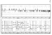
In der
- Der obere Graph zeigt die aktuelle IST-Temperatur (RT) des Wohnraums. Dabei ist auf der Abszisse die Zeit in Stunden (00.00 bis 12.00 Uhr) und auf der Ordinate die Raumtemperatur in Zehntelgraden und Fünfzigstelgraden Celsius dargestellt. Es darf festgestellt werden, dass diese Wohnraumtemperatur über eine
Zeit von 12 Stunden (Mitternacht bis Mittag) sehr konstant auf 21.3 °C gehalten werden konnte, wobei diese Temperatur nur um +/- 0.1 °C von diesem Mittelwert abwich. Die gemessene Aussentemperatur betrug um Mitternacht (00.00 Uhr) -6 °C und am darauffolgenden Mittag (12.00 Uhr) +2 °C. - Der untere Graph zeigt die Vorlauftemperatur (VL), die sich in einem Bereich von ca. 30
bis 36 °C bewegte. Dabei ist auf der Abszisse die Zeit in Stunden (00.00 bis 12.00 Uhr) und auf der Ordinate die Temperatur inSchritten von 3 °C dargestellt. Die beiden Rücklauftemperaturen (RL1,RL2) bewegten sich entsprechend der gewählten Temperaturdifferenz in einemBereich von 24bis 30 °C. Der untere Graph zeigt zudem die Stellgliedsignale (SG1,SG2) für diebeiden Ventile 9,9'; wobei die unterschiedlichen Zeitpunkte des Veränderns dieser Signale (1/0 bzw. 0/1) belegen, dass jeder der beiden Heizkreise bzw. jede der beiden Temperieranordnungen 5,5' autonom, d.h. unabhängig vom anderen Heizkreis gesteuert wurde.
- The upper graph shows the current ACTUAL temperature (RT) of the living space. The abscissa shows the time in hours (00.00 to 12.00 o'clock) and the ordinate the room temperature in tenths of degrees and fifty degrees centigrade. It may be stated that this room temperature could be kept very constant at 21.3 ° C over a period of 12 hours (midnight to noon), with this temperature only deviating by +/- 0.1 ° C from this average. The measured outside temperature was -6 ° C at midnight (00.00) and +2 ° C the following afternoon (12.00).
- The lower graph shows the flow temperature (VL), which was in the range of about 30 to 36 ° C. The abscissa shows the time in hours (00.00 to 12.00 o'clock) and the ordinate shows the temperature in steps of 3 ° C. The two return temperatures (RL 1 , RL 2 ) varied according to the selected temperature difference in a range of 24 to 30 ° C. The lower graph also shows the actuator signals (SG 1 , SG 2 ) for the two
valves 9, 9 '; wherein the different points in time of changing these signals (1/0 or 0/1) prove that each of the two heating circuits or each of the twotemperature control arrangements 5, 5 'was controlled autonomously, ie independently of the other heating circuit.
Dieses Beispiel zeigt, dass die Temperatur eines Wohnraums mit diesem relativ einfachen Temperierverfahren trotz unterschiedlichen Aussentemperaturen sehr exakt geregelt werden kann.This example shows that the temperature of a living space can be controlled very precisely with this relatively simple tempering process, despite different outside temperatures.
Die
Die
Die
Die
Die
Aus den
Die
Im Zusammenhang mit der vorliegenden Erfindung wird als Temperierfluid 2 jede Flüssigkeit, jedes Gas und jedes Gas-Flüssigkeits-Gemisch verstanden, die bzw. das zum Heizen (Zuführen von Energie) und/oder zum Kühlen (Abführen von Energie) und somit auch zum Transportieren von Energie bzw. Wärme verwendet werden kann. In Bodenheizungen kann beispielsweise eine Wasser-Frostschutz-Mischung verwendet werden und in Kühlkreisläufen wird oft eine Flüssigkeit mit einer hohen Verdampfungswärme-Kapazität benutzt. Als Temperiervorrichtungen 3 kommen beispielsweise ein Pellet-, Gas- bzw. Öl-Brenner mit einem Heizkessel oder ein Kühlaggregat mit einem Kühlmittelbehälter in Frage.In the context of the present invention, tempering
Im Zusammenhang mit der vorliegenden Erfindung kann als zu temperierendes Bauteil 4 ein Boden oder mehrere Böden, eine oder mehrere Wände und/oder eine Decke oder mehrere Decken von Wohn- oder Arbeits-Räumen betrachtet werden. Diese Bauteile können beispielsweise auch bei Lagerräumen oder bei Ausstellungsräumen vorhanden sein. Diese Bauteile können aber auch als allein stehende, hängende oder liegende Heiz- oder Kühlwände ausgebildet sein.In the context of the present invention, one or more floors, one or more walls and / or a ceiling or several ceilings of living or working spaces can be considered as the
Als beispielhafte fluidische Verbindung in Temperiersystemen 1,1' gelten hier Leitungen zum Leiten von Temperierfluiden, wie Rohre und dergleichen. Als beispielhafte elektrische Verbindungen in Temperiersystemen 1,1' gelten hier elektrische Kabel zum Leiten von elektrischen Signalen aber auch drahtlose Verbindungen zum Übertragen von elektronischen Daten oder Signalen.As an exemplary fluidic connection in
Die Ventile 9,9' sind vorzugsweise als Fluss-Regelventile ausgebildet und weisen im offenen Zustand vorzugsweise immer einen minimalen Öffnungsgrad auf, der einen minimalen Fluss des Temperierfluids 2 von 0.1 bis 2 l/min bedingt. Zudem wird bevorzugt, dass die Stellglieder 10,10' gefederte Stössel umfassen. Speziell werden Stellglieder 10,10' bevorzugt, die je eine elektrische Heizung und je eine in sich geschlossene Stellglied-Patrone mit temperaturabhängigem Volumen umfassen.The
Gleiche Bezugszeichen beziehen sich auf entsprechende Vorrichtungsmerkmale.Like reference numerals refer to corresponding device features.
- 1,1'1,1 '
- TemperiersystemTemperature System
- 22
- Temperierfluidtempering
- 33
- Temperiervorrichtungtempering
- 44
- Bauteilcomponent
- 5,5'5.5 '
- TemperieranordnungTemperature control order
- 66
- Vorlaufleitung, gemeinsame VorlaufleitungSupply line, common supply line
- 6',6"6 ', 6 "
- separate Vorlaufleitungenseparate flow lines
- 7,7'7,7 '
- RücklaufleitungReturn line
- 88th
- Steuerungcontrol
- 9,9'9.9 '
- VentilValve
- 10,10'10.10 '
- Stellgliedactuator
- 1111
- VorlauftemperaturfühlerFlow temperature sensor
- 12,12'12.12 '
- RücklauftemperaturfühlerReturn temperature sensor
- 1313
- Reglerregulator
- 1414
- Thermostatthermostat
- 1515
- Bimetall-Stellglied/ReglerBimetallic actuator / controller
- 1616
- Hubstroke
- 1717
- Schmitt-TriggerSchmitt trigger
- 1818
- Expansions-StellgliedExpansion actuator
- 1919
- Differenz-VerstärkerDifferential amplifier
- 2020
- Elektromotor,Electric motor,
- 2121
- Elektromotor-Stellglied MikroprozessorElectric motor actuator microprocessor
- 2222
- Solenoid-StellgliedSolenoid actuator
- 2323
- VorlaufverteilerbalkenFlow manifold bar
- 23'23 '
- RücklaufverteilerbalkenReturn manifold bar
- 2424
- Abschlussventiloff valve
Claims (16)
wobei das Temperiersystem (1) umfasst:
dadurch gekennzeichnet, dass die Steuerung (8) einen Regler (13) umfasst, mit welchem eine Temperaturdifferenz zwischen der Vorlauftemperatur und der Rücklauftemperatur des Temperierfluids (2) erfasst wird, wobei der Regler (13) ausgehend von dieser Temperaturdifferenz das Stellglied (10) des Ventils (9) derart zum Einstellen des Öffnungsgrades des Ventils (9) veranlasst, dass die mittlere Temperaturdifferenz zwischen der Vorlauftemperatur und der Rücklauftemperatur des Temperierfluids (2) in einem vorbestimmten Wertebereich liegt.Method for tempering a component (4) with a tempering system;
wherein the tempering system (1) comprises:
characterized in that the controller (8) comprises a regulator (13) with which a temperature difference between the flow temperature and the return temperature of the tempering fluid (2) is detected, wherein the controller (13) based on this temperature difference, the actuator (10) of the Valve (9) for adjusting the opening degree of the valve (9) causes the mean temperature difference between the flow temperature and the return temperature of the tempering fluid (2) is in a predetermined range of values.
wobei der Regler (13) die jeweiligen Temperaturdifferenzen zwischen der gemeinsamen, durch den Vorlauftemperaturfühler (11) erfassten Vorlauftemperatur und den 2 bis n individuellen durch die Rücklauftemperaturfühler (12,12') erfassten Rücklauftemperaturen des Temperierfluids (2) erfasst,
wobei mit dem Regler (13) der Steuerung (8) je eine individuelle Temperaturdifferenz zwischen der Vorlauftemperatur und je einer der 2 bis n Rücklauftemperaturen des Temperierfluids (2) erfasst wird, und
wobei der Regler (13), ausgehend von diesen individuellen Temperaturdifferenzen die Stellglieder (10,10') der 2 bis n Ventile (9,9') derart zum Einstellen des Öffnungsgrades dieser Ventile (9,9') veranlasst, dass die individuellen mittleren Temperaturdifferenzen zwischen der Vorlauftemperatur und der jeweiligen Rücklauftemperatur des Temperierfluids (2) in je einem vorbestimmten Wertebereich liegen.
wherein the controller (13) detects the respective temperature differences between the common flow temperature detected by the flow temperature sensor (11) and the 2 to n individual return temperatures of the tempering fluid (2) detected by the return temperature sensors (12, 12 '),
wherein an individual temperature difference between the flow temperature and one of the 2 to n return temperatures of the tempering fluid (2) is detected by the controller (13) of the controller (8), and
the regulator (13), based on these individual temperature differences, causing the actuators (10, 10 ') of the 2 to n valves (9, 9') to adjust the degree of opening of these valves (9, 9 ') such that the individual mean Temperature differences between the flow temperature and the respective return temperature of the tempering (2) are each in a predetermined range of values.
wobei das Temperiersystem (1) mindestens umfasst:
dadurch gekennzeichnet, dass die Steuerung (8) einen Regler (13) umfasst, der zum Erfassen einer Temperaturdifferenz zwischen der Vorlauftemperatur und der Rücklauftemperatur des Temperierfluids (2) ausgebildet ist, wobei der Regler (13) so ausgebildet ist, dass er ausgehend von dieser Temperaturdifferenz das Stellglied (10) des Ventils (9) derart zum Einstellen des Öffnungsgrades des Ventils (9) veranlasst, dass die mittlere Temperaturdifferenz zwischen der Vorlauftemperatur und der Rücklauftemperatur des Temperierfluids (2) in einem vorbestimmten Wertebereich liegt.
wherein the tempering system (1) comprises at least:
characterized in that the controller (8) comprises a regulator (13) which is designed to detect a temperature difference between the flow temperature and the return temperature of the tempering fluid (2), wherein the controller (13) is designed so that it starts from this Temperature difference, the actuator (10) of the valve (9) for adjusting the opening degree of the valve (9) causes the average temperature difference between the flow temperature and the return temperature of the tempering fluid (2) is in a predetermined range of values.
Applications Claiming Priority (1)
| Application Number | Priority Date | Filing Date | Title |
|---|---|---|---|
| CH00266/12A CH706146A2 (en) | 2012-02-29 | 2012-02-29 | Method and system for tempering components. |
Publications (3)
| Publication Number | Publication Date |
|---|---|
| EP2653789A2 true EP2653789A2 (en) | 2013-10-23 |
| EP2653789A3 EP2653789A3 (en) | 2018-04-18 |
| EP2653789B1 EP2653789B1 (en) | 2020-01-15 |
Family
ID=47900551
Family Applications (1)
| Application Number | Title | Priority Date | Filing Date |
|---|---|---|---|
| EP13156578.0A Active EP2653789B1 (en) | 2012-02-29 | 2013-02-25 | Method and system for tempering components |
Country Status (3)
| Country | Link |
|---|---|
| US (1) | US9267694B2 (en) |
| EP (1) | EP2653789B1 (en) |
| CH (1) | CH706146A2 (en) |
Cited By (5)
| Publication number | Priority date | Publication date | Assignee | Title |
|---|---|---|---|---|
| DE102017123560A1 (en) | 2017-10-10 | 2019-04-11 | Eut Edelstahl Umformtechnik Gmbh | Self-regulating adjusting device for a flow control valve, a tempering system as well as a distributor device with the same, and method for this |
| US10697650B2 (en) | 2016-07-27 | 2020-06-30 | Computime Ltd. | Automatic balance valve control |
| US10712021B2 (en) | 2018-06-27 | 2020-07-14 | Computime Ltd. | Pulse modulated heating, ventilation, and air conditioning (HVAC) control |
| US10739017B2 (en) | 2018-08-20 | 2020-08-11 | Computime Ltd. | Determination of hydronic valve opening point |
| DE102019120126A1 (en) * | 2019-07-25 | 2021-01-28 | Straub Kg | Setting device and method for determining a hydraulic threshold value of a valve |
Families Citing this family (12)
| Publication number | Priority date | Publication date | Assignee | Title |
|---|---|---|---|---|
| US9091240B2 (en) * | 2013-01-24 | 2015-07-28 | Caterpillar Inc. | Compressed natural gas fuel mass control system |
| DE102013114925A1 (en) * | 2013-12-27 | 2015-07-02 | Agratec Invest Ag | Biogas production process and biogas production device |
| EP3686708B1 (en) * | 2014-03-18 | 2025-05-07 | Imi Hydronic Engineering, Inc. | Ad-hoc network for a system using a fluid to transfer thermal energy |
| JP6458649B2 (en) * | 2015-06-01 | 2019-01-30 | 富士通株式会社 | COOLING DEVICE, COOLING METHOD, AND INFORMATION PROCESSING SYSTEM |
| DK179749B1 (en) * | 2016-06-30 | 2019-05-07 | Danfoss A/S | Control of flow regulating device |
| JP6804740B2 (en) * | 2017-02-27 | 2020-12-23 | 清水建設株式会社 | Radiant air conditioning system |
| US20180298611A1 (en) * | 2017-04-17 | 2018-10-18 | David R. Hall | Configurable Hydronic Structural Panel |
| CN108509001B (en) * | 2018-04-02 | 2021-01-15 | 联想(北京)有限公司 | Electronic equipment and water-cooling server thereof |
| US20200149748A1 (en) * | 2018-11-14 | 2020-05-14 | Francesco Giovanni Longo | Building System |
| US11092354B2 (en) | 2019-06-20 | 2021-08-17 | Johnson Controls Tyco IP Holdings LLP | Systems and methods for flow control in an HVAC system |
| US11149976B2 (en) * | 2019-06-20 | 2021-10-19 | Johnson Controls Tyco IP Holdings LLP | Systems and methods for flow control in an HVAC system |
| CN112032818B (en) * | 2020-08-02 | 2022-01-14 | 杭州云谷科技股份有限公司 | Room temperature cooperative control method for water system heating |
Citations (1)
| Publication number | Priority date | Publication date | Assignee | Title |
|---|---|---|---|---|
| DE4417941A1 (en) | 1994-05-21 | 1995-11-23 | Johann Binder | Floor heating element connection device for advance and return of heating system |
Family Cites Families (58)
| Publication number | Priority date | Publication date | Assignee | Title |
|---|---|---|---|---|
| GB1025727A (en) * | 1963-10-31 | 1966-04-14 | Ranco Inc | Ice bank control circuits |
| GB2034111B (en) | 1978-10-03 | 1983-02-16 | British Gas Corp | Temperature sensing device and apparatus for balancing wetcentral heating systems |
| DE2943081A1 (en) | 1979-10-25 | 1981-05-14 | Robert Bosch Gmbh, 7000 Stuttgart | COLLECTIVE HEATING WITH A CIRCULATING HEATING MEDIUM |
| US4363441A (en) * | 1980-04-23 | 1982-12-14 | Emanuel Feinberg | Thermal energy usage meter for multiple unit building |
| SE8006391L (en) * | 1980-09-12 | 1982-03-13 | Jacob Weitman | WAY TO CONTROL A SWITCH EXCHANGE |
| GB2095379B (en) * | 1981-03-24 | 1984-11-14 | Exxon Research Engineering Co | Method and apparatus for regulating fluid flows in parallel-connected conduits |
| US4745767A (en) * | 1984-07-26 | 1988-05-24 | Sanyo Electric Co., Ltd. | System for controlling flow rate of refrigerant |
| DE3445634C2 (en) * | 1984-12-14 | 1993-12-09 | Held Kurt | Method and device for heating the heatable machine parts of a double belt press |
| EP0189614B1 (en) | 1984-12-24 | 1989-03-15 | Nederlandse Organisatie voor toegepast-natuurwetenschappelijk onderzoek TNO | Apparatus and method for adjusting a central heating installation |
| DE3545602C1 (en) * | 1985-12-21 | 1987-08-13 | Danfoss As | Control circuit for a cooling device |
| JP2640682B2 (en) * | 1988-10-27 | 1997-08-13 | ファナック株式会社 | Abnormal display method of machining fluid temperature of wire electric discharge machine |
| US5144811A (en) * | 1991-01-10 | 1992-09-08 | Hughes Aircraft Company | Condensation control system for water-cooled electronics |
| US5244148A (en) * | 1992-07-30 | 1993-09-14 | Fluidmaster, Inc. | Adaptable heater control |
| US5435379A (en) * | 1992-08-14 | 1995-07-25 | Texas Instruments Incorporated | Method and apparatus for low-temperature semiconductor processing |
| US5643482A (en) * | 1996-01-16 | 1997-07-01 | Heat Timer Corporation | Snow melt control system |
| JPH1019283A (en) * | 1996-07-01 | 1998-01-23 | Sunpot Co Ltd | Hot water heating system |
| DE19911866B4 (en) * | 1999-03-17 | 2018-10-18 | Xylem Ip Holdings Llc | Device for balancing heating circuits in large surface heating systems |
| US6711017B2 (en) * | 2001-07-17 | 2004-03-23 | Hitachi Kokusai Electric Inc. | Cooling apparatus for electronic unit |
| US6817408B2 (en) * | 2001-10-17 | 2004-11-16 | Graham Corporation | Heat exchanger with integral internal temperature sensor |
| US8463441B2 (en) * | 2002-12-09 | 2013-06-11 | Hudson Technologies, Inc. | Method and apparatus for optimizing refrigeration systems |
| DE10310282A1 (en) * | 2003-03-07 | 2004-09-16 | Rittal Gmbh & Co. Kg | Liquid cooling system |
| GB0317330D0 (en) * | 2003-07-24 | 2003-08-27 | Diamond H Controls Ltd | Gas valve mechanism and multi-port valve |
| NL1025309C2 (en) | 2004-01-23 | 2005-07-26 | Nedap Nv | System for independently controlling the temperatures in different rooms and the temperatures of one or more hot water boilers. |
| US7477950B2 (en) * | 2004-09-28 | 2009-01-13 | Dymocom, Inc. | Method and system for controlling a network of water appliances |
| JP2006215882A (en) * | 2005-02-04 | 2006-08-17 | Hitachi Ltd | Disk array device and liquid cooling device thereof |
| GB2428282B (en) * | 2005-07-14 | 2007-05-09 | David Neill | Heating/cooling systems |
| JP4534227B2 (en) * | 2005-09-30 | 2010-09-01 | Smc株式会社 | Water-cooled constant temperature liquid circulating apparatus and circulating liquid temperature control method in the apparatus |
| CN101421560B (en) | 2006-02-10 | 2010-06-23 | 丹佛斯公司 | Control of large heat capacity systems |
| US7510174B2 (en) * | 2006-04-14 | 2009-03-31 | Kammerzell Larry L | Dew point cooling tower, adhesive bonded heat exchanger, and other heat transfer apparatus |
| US7454308B1 (en) * | 2006-05-09 | 2008-11-18 | Steven Wayne Carroll | System for detection of waterlogging in steam heating coils |
| JP4254838B2 (en) * | 2006-10-11 | 2009-04-15 | コニカミノルタビジネステクノロジーズ株式会社 | Image processing system, image processing apparatus, and program |
| US8430068B2 (en) * | 2007-05-31 | 2013-04-30 | James Wallace Harris | Cooling system having inlet control and outlet regulation |
| KR101068471B1 (en) * | 2007-11-12 | 2011-09-29 | 주식회사 경동네트웍 | Hot water system and its control method |
| US7808780B2 (en) * | 2008-02-28 | 2010-10-05 | International Business Machines Corporation | Variable flow computer cooling system for a data center and method of operation |
| US8763414B2 (en) * | 2008-03-31 | 2014-07-01 | Google Inc. | Warm floor data center |
| FR2931226B1 (en) * | 2008-05-19 | 2013-08-16 | Acome Soc Coop Production | METHOD AND SYSTEM FOR CONTROLLING A HYDRAULIC CIRCUIT WITH SEVERAL HEAT EXCHANGE LOOPS |
| US20100100090A1 (en) * | 2008-10-17 | 2010-04-22 | Medicold Limited | Thermotherapy application and control system |
| DE102009004319A1 (en) * | 2009-01-10 | 2010-07-22 | Henry Klein | Method for performing hydraulic balance of heat exchanger of circulatory composite system in building, involves detecting return temperature at heat exchanger and controlling volumetric flow rate by heat exchanger as function of temperature |
| US8145363B2 (en) * | 2009-05-28 | 2012-03-27 | American Power Conversion Corporation | Systems and methods for controlling load dynamics in a pumped refrigerant cooling system |
| GB2471834A (en) * | 2009-07-09 | 2011-01-19 | Hewlett Packard Development Co | Cooling Module with a Chiller Unit, Flow Control, and Able to Utilise Free Cooling |
| US20110112693A1 (en) * | 2009-08-27 | 2011-05-12 | Jim Jiaming Ye | Water cooling system of building structure for air conditioning system |
| US8452459B2 (en) * | 2009-08-31 | 2013-05-28 | Fisher-Rosemount Systems, Inc. | Heat exchange network heat recovery optimization in a process plant |
| US8583290B2 (en) * | 2009-09-09 | 2013-11-12 | International Business Machines Corporation | Cooling system and method minimizing power consumption in cooling liquid-cooled electronics racks |
| US8113010B2 (en) * | 2009-11-02 | 2012-02-14 | Exaflop Llc | Data center cooling |
| US8286442B2 (en) * | 2009-11-02 | 2012-10-16 | Exaflop Llc | Data center with low power usage effectiveness |
| JP4854779B2 (en) * | 2009-12-09 | 2012-01-18 | シャープ株式会社 | Air conditioner, expansion valve opening control method and program |
| ES2351458B1 (en) * | 2010-03-16 | 2011-10-19 | Inventia 2007, S.L. | WATER SUPPLY SYSTEM WITH FLOW AND TEMPERATURE REGULATION. |
| AT12048U1 (en) * | 2010-03-23 | 2011-09-15 | Stefan Ing Petters | DEVICE FOR TRANSFERRING HEAT |
| JP5496771B2 (en) * | 2010-05-13 | 2014-05-21 | 株式会社Kelk | Temperature control method using temperature control device |
| US20130205822A1 (en) * | 2010-07-06 | 2013-08-15 | Peter Heiland | System and method for cooling a computer system |
| US9158312B2 (en) * | 2010-07-07 | 2015-10-13 | Grand Mate Co., Ltd. | Method and device for controlling outlet water temperature of water heater |
| WO2012037516A2 (en) * | 2010-09-17 | 2012-03-22 | Safoco, Inc. | Valve actuator control system and method of use |
| US8757504B2 (en) * | 2010-10-22 | 2014-06-24 | Tai-Her Yang | Temperature unifying and heat storing system of semiconductor heat loss through natural temperature maintaining member |
| US9631831B2 (en) * | 2010-11-17 | 2017-04-25 | Bilimo Holding Ag | Method for controlling the opening of an HVAC valve based on the energy-per-flow gradient |
| US20120197446A1 (en) * | 2010-12-01 | 2012-08-02 | Glaudel Stephen P | Advanced feed-forward valve-control for a mass flow controller |
| JP5694018B2 (en) * | 2011-03-16 | 2015-04-01 | 株式会社日本自動車部品総合研究所 | Cooling system |
| CA2799677C (en) * | 2011-12-22 | 2017-01-24 | Cenovus Fccl Ltd. | Steam generator and method for generating steam |
| US9513019B2 (en) * | 2013-11-27 | 2016-12-06 | Advanced Conservation Technologies Development, Inc. | Methods and apparatus for remotely monitoring and/or controlling a plumbing system |
-
2012
- 2012-02-29 CH CH00266/12A patent/CH706146A2/en not_active Application Discontinuation
-
2013
- 2013-02-25 EP EP13156578.0A patent/EP2653789B1/en active Active
- 2013-02-26 US US13/777,600 patent/US9267694B2/en active Active
Patent Citations (1)
| Publication number | Priority date | Publication date | Assignee | Title |
|---|---|---|---|---|
| DE4417941A1 (en) | 1994-05-21 | 1995-11-23 | Johann Binder | Floor heating element connection device for advance and return of heating system |
Cited By (8)
| Publication number | Priority date | Publication date | Assignee | Title |
|---|---|---|---|---|
| US10697650B2 (en) | 2016-07-27 | 2020-06-30 | Computime Ltd. | Automatic balance valve control |
| DE102017123560A1 (en) | 2017-10-10 | 2019-04-11 | Eut Edelstahl Umformtechnik Gmbh | Self-regulating adjusting device for a flow control valve, a tempering system as well as a distributor device with the same, and method for this |
| WO2019072813A1 (en) | 2017-10-10 | 2019-04-18 | Eut Edelstahl Umformtechnik Gmbh | SELF-REGULATING ADJUSTMENT DEVICE FOR A FLOW CONTROL VALVE, A TEMPERATURE SYSTEM AS WELL AS A DISTRIBUTION DEVICE WITH THE SAME, AND METHOD THEREFOR |
| DE102017123560B4 (en) | 2017-10-10 | 2024-09-12 | Eut Edelstahl Umformtechnik Gmbh | Self-regulating adjustment device for a flow control valve |
| US10712021B2 (en) | 2018-06-27 | 2020-07-14 | Computime Ltd. | Pulse modulated heating, ventilation, and air conditioning (HVAC) control |
| US10739017B2 (en) | 2018-08-20 | 2020-08-11 | Computime Ltd. | Determination of hydronic valve opening point |
| DE102019120126A1 (en) * | 2019-07-25 | 2021-01-28 | Straub Kg | Setting device and method for determining a hydraulic threshold value of a valve |
| DE102019120126B4 (en) | 2019-07-25 | 2021-08-05 | Straub Kg | Adjustment device and method for determining a hydraulic threshold value of a valve |
Also Published As
| Publication number | Publication date |
|---|---|
| EP2653789B1 (en) | 2020-01-15 |
| US9267694B2 (en) | 2016-02-23 |
| CH706146A2 (en) | 2013-08-30 |
| US20130220590A1 (en) | 2013-08-29 |
| EP2653789A3 (en) | 2018-04-18 |
Similar Documents
| Publication | Publication Date | Title |
|---|---|---|
| EP2653789B1 (en) | Method and system for tempering components | |
| DE102017123560B4 (en) | Self-regulating adjustment device for a flow control valve | |
| EP1936288B1 (en) | Method and system for detecting the hydraulic balance of a heating system | |
| EP2965161B1 (en) | Method and system for the temperature control of components | |
| DE19804565C2 (en) | Self-learning control procedure | |
| DE102009004319A1 (en) | Method for performing hydraulic balance of heat exchanger of circulatory composite system in building, involves detecting return temperature at heat exchanger and controlling volumetric flow rate by heat exchanger as function of temperature | |
| EP2354682B1 (en) | Method and device for adjusting a tempering device | |
| EP3378928B1 (en) | Humidifying module and incubator or air conditioned cabinet with humidifying modul and method for operating a humidifying module | |
| EP1933220B1 (en) | Method of determining the supply state of a heating circuit or a building and supply state regulator | |
| DE102008049619A1 (en) | Building heating system has two heating circuits, which have heating fluid, and electronic actual flow rate comparison arithmetic unit | |
| EP3473939B1 (en) | Method for operating a heating assembly and heating assembly | |
| EP2175206B1 (en) | Method for tempering rooms in a building | |
| EP2009536A1 (en) | Method and device for setting the heating reserve | |
| DE10108852C1 (en) | Room temperature control | |
| DE102015222110A1 (en) | Method for carrying out an automated hydraulic balancing, valve and heating system for this purpose | |
| EP3553408A1 (en) | Hybrid heating device and method for operating a hybrid heating device | |
| DE102015113340A1 (en) | Heating system and method for operating a heating system | |
| DE102010056301B4 (en) | Method for the automatic optimization of a heating-up phase of a heating system and a heating system | |
| EP3425474B1 (en) | Method for controlling a thermoelectric on-off drive of a valve of a heating and/or cooling system | |
| EP2894408B1 (en) | Method for controlling the temperature in the rooms of a building | |
| EP1450111B1 (en) | Method for determining a heat requirement and heating apparatus for carrying out this method | |
| DE102018130192A1 (en) | Method for operating a control device and control device | |
| DE102011011965A1 (en) | Self-learning control method for controlling temperature for e.g. supplying heat to space, involves predetermining minimum temperature value, temperature set value and maximum temperature value | |
| DE102021132563A1 (en) | heating control | |
| DE102016102539A1 (en) | Method and system for controlling a plurality of radiators |
Legal Events
| Date | Code | Title | Description |
|---|---|---|---|
| PUAI | Public reference made under article 153(3) epc to a published international application that has entered the european phase |
Free format text: ORIGINAL CODE: 0009012 |
|
| AK | Designated contracting states |
Kind code of ref document: A2 Designated state(s): AL AT BE BG CH CY CZ DE DK EE ES FI FR GB GR HR HU IE IS IT LI LT LU LV MC MK MT NL NO PL PT RO RS SE SI SK SM TR |
|
| AX | Request for extension of the european patent |
Extension state: BA ME |
|
| PUAL | Search report despatched |
Free format text: ORIGINAL CODE: 0009013 |
|
| AK | Designated contracting states |
Kind code of ref document: A3 Designated state(s): AL AT BE BG CH CY CZ DE DK EE ES FI FR GB GR HR HU IE IS IT LI LT LU LV MC MK MT NL NO PL PT RO RS SE SI SK SM TR |
|
| AX | Request for extension of the european patent |
Extension state: BA ME |
|
| RIC1 | Information provided on ipc code assigned before grant |
Ipc: G05D 23/19 20060101ALI20180309BHEP Ipc: F24D 3/14 20060101ALI20180309BHEP Ipc: F24D 3/12 20060101AFI20180309BHEP Ipc: F24F 3/06 20060101ALI20180309BHEP Ipc: F24F 5/00 20060101ALI20180309BHEP Ipc: G05D 23/08 20060101ALI20180309BHEP Ipc: F24D 19/10 20060101ALI20180309BHEP |
|
| STAA | Information on the status of an ep patent application or granted ep patent |
Free format text: STATUS: REQUEST FOR EXAMINATION WAS MADE |
|
| 17P | Request for examination filed |
Effective date: 20180921 |
|
| RBV | Designated contracting states (corrected) |
Designated state(s): AL AT BE BG CH CY CZ DE DK EE ES FI FR GB GR HR HU IE IS IT LI LT LU LV MC MK MT NL NO PL PT RO RS SE SI SK SM TR |
|
| STAA | Information on the status of an ep patent application or granted ep patent |
Free format text: STATUS: EXAMINATION IS IN PROGRESS |
|
| 17Q | First examination report despatched |
Effective date: 20190405 |
|
| RIC1 | Information provided on ipc code assigned before grant |
Ipc: G05D 23/08 20060101ALI20190704BHEP Ipc: F24F 5/00 20060101ALI20190704BHEP Ipc: F24F 11/72 20180101ALI20190704BHEP Ipc: F24F 3/06 20060101ALI20190704BHEP Ipc: G05D 23/19 20060101ALI20190704BHEP Ipc: F24D 19/10 20060101ALI20190704BHEP Ipc: F24D 3/14 20060101ALI20190704BHEP Ipc: F24D 3/12 20060101AFI20190704BHEP |
|
| GRAP | Despatch of communication of intention to grant a patent |
Free format text: ORIGINAL CODE: EPIDOSNIGR1 |
|
| STAA | Information on the status of an ep patent application or granted ep patent |
Free format text: STATUS: GRANT OF PATENT IS INTENDED |
|
| INTG | Intention to grant announced |
Effective date: 20190828 |
|
| GRAJ | Information related to disapproval of communication of intention to grant by the applicant or resumption of examination proceedings by the epo deleted |
Free format text: ORIGINAL CODE: EPIDOSDIGR1 |
|
| STAA | Information on the status of an ep patent application or granted ep patent |
Free format text: STATUS: EXAMINATION IS IN PROGRESS |
|
| GRAP | Despatch of communication of intention to grant a patent |
Free format text: ORIGINAL CODE: EPIDOSNIGR1 |
|
| STAA | Information on the status of an ep patent application or granted ep patent |
Free format text: STATUS: GRANT OF PATENT IS INTENDED |
|
| INTC | Intention to grant announced (deleted) | ||
| RAP1 | Party data changed (applicant data changed or rights of an application transferred) |
Owner name: OBLAMATIK AG |
|
| GRAS | Grant fee paid |
Free format text: ORIGINAL CODE: EPIDOSNIGR3 |
|
| GRAA | (expected) grant |
Free format text: ORIGINAL CODE: 0009210 |
|
| STAA | Information on the status of an ep patent application or granted ep patent |
Free format text: STATUS: THE PATENT HAS BEEN GRANTED |
|
| INTG | Intention to grant announced |
Effective date: 20191120 |
|
| AK | Designated contracting states |
Kind code of ref document: B1 Designated state(s): AL AT BE BG CH CY CZ DE DK EE ES FI FR GB GR HR HU IE IS IT LI LT LU LV MC MK MT NL NO PL PT RO RS SE SI SK SM TR |
|
| REG | Reference to a national code |
Ref country code: CH Ref legal event code: EP Ref country code: GB Ref legal event code: FG4D Free format text: NOT ENGLISH |
|
| REG | Reference to a national code |
Ref country code: IE Ref legal event code: FG4D Free format text: LANGUAGE OF EP DOCUMENT: GERMAN |
|
| REG | Reference to a national code |
Ref country code: DE Ref legal event code: R096 Ref document number: 502013014200 Country of ref document: DE |
|
| REG | Reference to a national code |
Ref country code: AT Ref legal event code: REF Ref document number: 1225483 Country of ref document: AT Kind code of ref document: T Effective date: 20200215 |
|
| REG | Reference to a national code |
Ref country code: CH Ref legal event code: NV Representative=s name: OK PAT AG PATENTE MARKEN LIZENZEN, CH |
|
| REG | Reference to a national code |
Ref country code: NL Ref legal event code: FP |
|
| REG | Reference to a national code |
Ref country code: LT Ref legal event code: MG4D |
|
| PG25 | Lapsed in a contracting state [announced via postgrant information from national office to epo] |
Ref country code: NO Free format text: LAPSE BECAUSE OF FAILURE TO SUBMIT A TRANSLATION OF THE DESCRIPTION OR TO PAY THE FEE WITHIN THE PRESCRIBED TIME-LIMIT Effective date: 20200415 Ref country code: PT Free format text: LAPSE BECAUSE OF FAILURE TO SUBMIT A TRANSLATION OF THE DESCRIPTION OR TO PAY THE FEE WITHIN THE PRESCRIBED TIME-LIMIT Effective date: 20200607 Ref country code: RS Free format text: LAPSE BECAUSE OF FAILURE TO SUBMIT A TRANSLATION OF THE DESCRIPTION OR TO PAY THE FEE WITHIN THE PRESCRIBED TIME-LIMIT Effective date: 20200115 Ref country code: FI Free format text: LAPSE BECAUSE OF FAILURE TO SUBMIT A TRANSLATION OF THE DESCRIPTION OR TO PAY THE FEE WITHIN THE PRESCRIBED TIME-LIMIT Effective date: 20200115 |
|
| REG | Reference to a national code |
Ref country code: SK Ref legal event code: T3 Ref document number: E 34278 Country of ref document: SK |
|
| PG25 | Lapsed in a contracting state [announced via postgrant information from national office to epo] |
Ref country code: IS Free format text: LAPSE BECAUSE OF FAILURE TO SUBMIT A TRANSLATION OF THE DESCRIPTION OR TO PAY THE FEE WITHIN THE PRESCRIBED TIME-LIMIT Effective date: 20200515 Ref country code: HR Free format text: LAPSE BECAUSE OF FAILURE TO SUBMIT A TRANSLATION OF THE DESCRIPTION OR TO PAY THE FEE WITHIN THE PRESCRIBED TIME-LIMIT Effective date: 20200115 Ref country code: SE Free format text: LAPSE BECAUSE OF FAILURE TO SUBMIT A TRANSLATION OF THE DESCRIPTION OR TO PAY THE FEE WITHIN THE PRESCRIBED TIME-LIMIT Effective date: 20200115 Ref country code: LV Free format text: LAPSE BECAUSE OF FAILURE TO SUBMIT A TRANSLATION OF THE DESCRIPTION OR TO PAY THE FEE WITHIN THE PRESCRIBED TIME-LIMIT Effective date: 20200115 Ref country code: GR Free format text: LAPSE BECAUSE OF FAILURE TO SUBMIT A TRANSLATION OF THE DESCRIPTION OR TO PAY THE FEE WITHIN THE PRESCRIBED TIME-LIMIT Effective date: 20200416 Ref country code: BG Free format text: LAPSE BECAUSE OF FAILURE TO SUBMIT A TRANSLATION OF THE DESCRIPTION OR TO PAY THE FEE WITHIN THE PRESCRIBED TIME-LIMIT Effective date: 20200415 |
|
| REG | Reference to a national code |
Ref country code: DE Ref legal event code: R097 Ref document number: 502013014200 Country of ref document: DE |
|
| PG25 | Lapsed in a contracting state [announced via postgrant information from national office to epo] |
Ref country code: EE Free format text: LAPSE BECAUSE OF FAILURE TO SUBMIT A TRANSLATION OF THE DESCRIPTION OR TO PAY THE FEE WITHIN THE PRESCRIBED TIME-LIMIT Effective date: 20200115 Ref country code: LT Free format text: LAPSE BECAUSE OF FAILURE TO SUBMIT A TRANSLATION OF THE DESCRIPTION OR TO PAY THE FEE WITHIN THE PRESCRIBED TIME-LIMIT Effective date: 20200115 Ref country code: DK Free format text: LAPSE BECAUSE OF FAILURE TO SUBMIT A TRANSLATION OF THE DESCRIPTION OR TO PAY THE FEE WITHIN THE PRESCRIBED TIME-LIMIT Effective date: 20200115 Ref country code: ES Free format text: LAPSE BECAUSE OF FAILURE TO SUBMIT A TRANSLATION OF THE DESCRIPTION OR TO PAY THE FEE WITHIN THE PRESCRIBED TIME-LIMIT Effective date: 20200115 Ref country code: SM Free format text: LAPSE BECAUSE OF FAILURE TO SUBMIT A TRANSLATION OF THE DESCRIPTION OR TO PAY THE FEE WITHIN THE PRESCRIBED TIME-LIMIT Effective date: 20200115 Ref country code: RO Free format text: LAPSE BECAUSE OF FAILURE TO SUBMIT A TRANSLATION OF THE DESCRIPTION OR TO PAY THE FEE WITHIN THE PRESCRIBED TIME-LIMIT Effective date: 20200115 Ref country code: LU Free format text: LAPSE BECAUSE OF NON-PAYMENT OF DUE FEES Effective date: 20200225 Ref country code: MC Free format text: LAPSE BECAUSE OF FAILURE TO SUBMIT A TRANSLATION OF THE DESCRIPTION OR TO PAY THE FEE WITHIN THE PRESCRIBED TIME-LIMIT Effective date: 20200115 |
|
| REG | Reference to a national code |
Ref country code: CH Ref legal event code: PFUS Owner name: OBLAMATIK AG, CH Free format text: FORMER OWNER: OBLAMATIK AG, CH |
|
| PLBE | No opposition filed within time limit |
Free format text: ORIGINAL CODE: 0009261 |
|
| STAA | Information on the status of an ep patent application or granted ep patent |
Free format text: STATUS: NO OPPOSITION FILED WITHIN TIME LIMIT |
|
| 26N | No opposition filed |
Effective date: 20201016 |
|
| PG25 | Lapsed in a contracting state [announced via postgrant information from national office to epo] |
Ref country code: IE Free format text: LAPSE BECAUSE OF NON-PAYMENT OF DUE FEES Effective date: 20200225 Ref country code: FR Free format text: LAPSE BECAUSE OF NON-PAYMENT OF DUE FEES Effective date: 20200315 |
|
| PG25 | Lapsed in a contracting state [announced via postgrant information from national office to epo] |
Ref country code: PL Free format text: LAPSE BECAUSE OF FAILURE TO SUBMIT A TRANSLATION OF THE DESCRIPTION OR TO PAY THE FEE WITHIN THE PRESCRIBED TIME-LIMIT Effective date: 20200115 Ref country code: SI Free format text: LAPSE BECAUSE OF FAILURE TO SUBMIT A TRANSLATION OF THE DESCRIPTION OR TO PAY THE FEE WITHIN THE PRESCRIBED TIME-LIMIT Effective date: 20200115 |
|
| GBPC | Gb: european patent ceased through non-payment of renewal fee |
Effective date: 20200415 |
|
| PG25 | Lapsed in a contracting state [announced via postgrant information from national office to epo] |
Ref country code: GB Free format text: LAPSE BECAUSE OF NON-PAYMENT OF DUE FEES Effective date: 20200415 |
|
| PG25 | Lapsed in a contracting state [announced via postgrant information from national office to epo] |
Ref country code: TR Free format text: LAPSE BECAUSE OF FAILURE TO SUBMIT A TRANSLATION OF THE DESCRIPTION OR TO PAY THE FEE WITHIN THE PRESCRIBED TIME-LIMIT Effective date: 20200115 Ref country code: MT Free format text: LAPSE BECAUSE OF FAILURE TO SUBMIT A TRANSLATION OF THE DESCRIPTION OR TO PAY THE FEE WITHIN THE PRESCRIBED TIME-LIMIT Effective date: 20200115 Ref country code: CY Free format text: LAPSE BECAUSE OF FAILURE TO SUBMIT A TRANSLATION OF THE DESCRIPTION OR TO PAY THE FEE WITHIN THE PRESCRIBED TIME-LIMIT Effective date: 20200115 |
|
| PG25 | Lapsed in a contracting state [announced via postgrant information from national office to epo] |
Ref country code: MK Free format text: LAPSE BECAUSE OF FAILURE TO SUBMIT A TRANSLATION OF THE DESCRIPTION OR TO PAY THE FEE WITHIN THE PRESCRIBED TIME-LIMIT Effective date: 20200115 Ref country code: AL Free format text: LAPSE BECAUSE OF FAILURE TO SUBMIT A TRANSLATION OF THE DESCRIPTION OR TO PAY THE FEE WITHIN THE PRESCRIBED TIME-LIMIT Effective date: 20200115 |
|
| REG | Reference to a national code |
Ref country code: DE Ref legal event code: R082 Ref document number: 502013014200 Country of ref document: DE Representative=s name: SKM-IP SCHMID KRAUSS KUTTENKEULER MALESCHA SCH, DE Ref country code: DE Ref legal event code: R082 Ref document number: 502013014200 Country of ref document: DE Representative=s name: COHAUSZ & FLORACK PATENT- UND RECHTSANWAELTE P, DE |
|
| PGFP | Annual fee paid to national office [announced via postgrant information from national office to epo] |
Ref country code: CZ Payment date: 20240214 Year of fee payment: 12 Ref country code: SK Payment date: 20240115 Year of fee payment: 12 |
|
| PGFP | Annual fee paid to national office [announced via postgrant information from national office to epo] |
Ref country code: CH Payment date: 20250301 Year of fee payment: 13 |
|
| REG | Reference to a national code |
Ref country code: SK Ref legal event code: MM4A Ref document number: E 34278 Country of ref document: SK Effective date: 20250225 |
|
| PG25 | Lapsed in a contracting state [announced via postgrant information from national office to epo] |
Ref country code: CZ Free format text: LAPSE BECAUSE OF NON-PAYMENT OF DUE FEES Effective date: 20250225 |
|
| PG25 | Lapsed in a contracting state [announced via postgrant information from national office to epo] |
Ref country code: SK Free format text: LAPSE BECAUSE OF NON-PAYMENT OF DUE FEES Effective date: 20250225 |
|
| PGFP | Annual fee paid to national office [announced via postgrant information from national office to epo] |
Ref country code: NL Payment date: 20260106 Year of fee payment: 14 |
|
| REG | Reference to a national code |
Ref country code: CH Ref legal event code: U11 Free format text: ST27 STATUS EVENT CODE: U-0-0-U10-U11 (AS PROVIDED BY THE NATIONAL OFFICE) Effective date: 20260301 |
|
| PGFP | Annual fee paid to national office [announced via postgrant information from national office to epo] |
Ref country code: DE Payment date: 20260102 Year of fee payment: 14 |
|
| PGFP | Annual fee paid to national office [announced via postgrant information from national office to epo] |
Ref country code: AT Payment date: 20260127 Year of fee payment: 14 |
|
| PGFP | Annual fee paid to national office [announced via postgrant information from national office to epo] |
Ref country code: BE Payment date: 20260105 Year of fee payment: 14 Ref country code: IT Payment date: 20260122 Year of fee payment: 14 |
|
| REG | Reference to a national code |
Ref country code: DE Ref legal event code: R082 Ref document number: 502013014200 Country of ref document: DE Representative=s name: COHAUSZ & FLORACK PATENT- UND RECHTSANWAELTE P, DE |