EP2654905B1 - Ensemble respiratoire pour avion avec dispositif renforcé de fixation du masque - Google Patents
Ensemble respiratoire pour avion avec dispositif renforcé de fixation du masque Download PDFInfo
- Publication number
- EP2654905B1 EP2654905B1 EP10819706.2A EP10819706A EP2654905B1 EP 2654905 B1 EP2654905 B1 EP 2654905B1 EP 10819706 A EP10819706 A EP 10819706A EP 2654905 B1 EP2654905 B1 EP 2654905B1
- Authority
- EP
- European Patent Office
- Prior art keywords
- support
- storage unit
- assembly according
- pin
- breathing assembly
- Prior art date
- Legal status (The legal status is an assumption and is not a legal conclusion. Google has not performed a legal analysis and makes no representation as to the accuracy of the status listed.)
- Not-in-force
Links
- 230000029058 respiratory gaseous exchange Effects 0.000 title claims description 98
- 239000000463 material Substances 0.000 claims description 3
- 239000007769 metal material Substances 0.000 claims description 3
- 239000004033 plastic Substances 0.000 claims description 3
- 230000002093 peripheral effect Effects 0.000 description 5
- QVGXLLKOCUKJST-UHFFFAOYSA-N atomic oxygen Chemical compound [O] QVGXLLKOCUKJST-UHFFFAOYSA-N 0.000 description 4
- 239000001301 oxygen Substances 0.000 description 4
- 229910052760 oxygen Inorganic materials 0.000 description 4
- 230000001133 acceleration Effects 0.000 description 3
- 239000007789 gas Substances 0.000 description 3
- 238000003780 insertion Methods 0.000 description 2
- 230000037431 insertion Effects 0.000 description 2
- 101100269850 Caenorhabditis elegans mask-1 gene Proteins 0.000 description 1
- 239000004743 Polypropylene Substances 0.000 description 1
- 229910000831 Steel Inorganic materials 0.000 description 1
- -1 polypropylene Polymers 0.000 description 1
- 229920001155 polypropylene Polymers 0.000 description 1
- 230000000717 retained effect Effects 0.000 description 1
- 239000010959 steel Substances 0.000 description 1
- 238000005728 strengthening Methods 0.000 description 1
Images


Classifications
-
- A—HUMAN NECESSITIES
- A62—LIFE-SAVING; FIRE-FIGHTING
- A62B—DEVICES, APPARATUS OR METHODS FOR LIFE-SAVING
- A62B25/00—Devices for storing or holding or carrying respiratory or breathing apparatus
-
- A—HUMAN NECESSITIES
- A62—LIFE-SAVING; FIRE-FIGHTING
- A62B—DEVICES, APPARATUS OR METHODS FOR LIFE-SAVING
- A62B25/00—Devices for storing or holding or carrying respiratory or breathing apparatus
- A62B25/005—Devices for storing or holding or carrying respiratory or breathing apparatus for high altitude
-
- A—HUMAN NECESSITIES
- A62—LIFE-SAVING; FIRE-FIGHTING
- A62B—DEVICES, APPARATUS OR METHODS FOR LIFE-SAVING
- A62B7/00—Respiratory apparatus
- A62B7/14—Respiratory apparatus for high-altitude aircraft
-
- B—PERFORMING OPERATIONS; TRANSPORTING
- B64—AIRCRAFT; AVIATION; COSMONAUTICS
- B64D—EQUIPMENT FOR FITTING IN OR TO AIRCRAFT; FLIGHT SUITS; PARACHUTES; ARRANGEMENT OR MOUNTING OF POWER PLANTS OR PROPULSION TRANSMISSIONS IN AIRCRAFT
- B64D10/00—Flight suits
-
- B—PERFORMING OPERATIONS; TRANSPORTING
- B64—AIRCRAFT; AVIATION; COSMONAUTICS
- B64D—EQUIPMENT FOR FITTING IN OR TO AIRCRAFT; FLIGHT SUITS; PARACHUTES; ARRANGEMENT OR MOUNTING OF POWER PLANTS OR PROPULSION TRANSMISSIONS IN AIRCRAFT
- B64D11/00—Passenger or crew accommodation; Flight-deck installations not otherwise provided for
- B64D11/06—Arrangements of seats, or adaptations or details specially adapted for aircraft seats
- B64D11/0689—Arrangements of seats, or adaptations or details specially adapted for aircraft seats specially adapted for pilots
-
- B—PERFORMING OPERATIONS; TRANSPORTING
- B64—AIRCRAFT; AVIATION; COSMONAUTICS
- B64D—EQUIPMENT FOR FITTING IN OR TO AIRCRAFT; FLIGHT SUITS; PARACHUTES; ARRANGEMENT OR MOUNTING OF POWER PLANTS OR PROPULSION TRANSMISSIONS IN AIRCRAFT
- B64D2231/00—Emergency oxygen systems
- B64D2231/02—Supply or distribution systems
- B64D2231/025—Oxygen masks; Mask storages; Features related to mask deployment
Definitions
- the invention relates to a breathing assembly essentially comprising a breathing mask and a storage unit for aircraft.
- a breathing assembly is generally placed in a cabin of a civil aircraft and intended to be used by a crew member, generally one of the pilots.
- the storage unit has to be placed near the pilot.
- the storage unit is sometimes fastened to a wall of the cabin.
- the storage unit is mounted on a seat next to the headrest of the seat.
- the breathing mask must be secured to the storage unit, even in severe conditions, such as very high acceleration or deceleration, due in particular to a crash, in order to prevent the breathing mask from being thrown into the cabin and possibly hitting the pilot.
- the purpose of this invention is to reduce the risk that the breathing mask unwittingly leaves the storage unit.
- the support further has at least one maintaining element disposed at the distal end of the support along the sliding direction
- the storage unit further has a maintaining element and, in the storage position, the sliding surface of the support is prevented from moving away from (maintained in contact with) the guiding surface of the storage unit along the elevation direction at the distal end by engagement of the maintaining element of the support with the maintaining element of the storage unit.
- the maintaining element of the support engages the maintaining element of the storage unit along a maintaining length along the sliding direction, and the storage position is spaced from the exit position by a distance at least three times as long as said maintaining length.
- the breathing mask can be tightly maintained relative to the storage unit in the storage position without substantially increasing the friction between the support and the storage unit during sliding of the support between the storage position and the exit position.
- the maintaining length is preferably lower than 15 millimetres, more preferably lower that 10 millimetres.
- a clearance lower than 0.5 millimetre, more preferably lower than 0.1 millimetre is placed between the maintaining element of the support and the maintaining element of the storage unit.
- the support is accurately maintained relative to the storage unit in the storage position without requiring low dimensional tolerances and without creating high friction between the support and the storage unit in the storage position.
- the securing device comprises a lever and a protruding portion and, in the storage position of the support and in the secure state of the securing device, the lever has an abutment portion which abuts against the protruding portion along the sliding direction.
- the user can easily move the securing device between the secure state and the release state, and the securing device efficiently secures the support to the storage when it is in its secure state.
- the sliding surface of the support is prevented from moving away from the guiding surface of the storage unit along the elevation direction at the proximal end by engagement of the protruding portion with the lever.
- the breathing assembly preferably further has the following supplementary characteristics:
- edge of the abutment portion of the lever has a length at least twice as long as a length of the edge of the protruding portion.
- the guiding surface of the storage cup preferably comprises two distant portions connected one to the other through a rigid bridge.
- one amongst the maintaining element of the storage unit and the maintaining element of the support is a groove extending in the sliding direction and the other is a protrusion protruding in a transversal direction perpendicular to the sliding direction and to the elevation direction, the protrusion engaging the groove in the storage position.
- one amongst the maintaining element of the storage unit and the maintaining element of the support is a pin extending in the sliding direction and the other is a hole, and the pin is inserted in said hole when the rigid support is in the storage position.
- the breathing assembly preferably further has the following characteristics:
- the first pin, the second pin, the first hole and the second hole prevent the breathing mask from rotating around the sliding direction relative to the storage unit when the breathing mask is in the storage position.
- the first pin in the storage position, has a first length extending through the first hole and the second pin has a second length extending through the second hole, and the first length is preferably at least ten percent longer than the second length.
- the breathing mask has preferably the following characteristics:
- the support is accurately maintained relative to the storage unit in the storage position without requiring low dimensional tolerances concerning the relative positioning of the first pin, the second pin, the first hole and the second hole in the transversal direction.
- the breathing assembly preferably further has the following characteristics:
- the insertion of the pin in the hole is made easier and the maintaining of the breathing mask relative to the support in the storage position is improved without requiring low dimensional tolerances.
- the pin is in metallic material and the support is in plastic material.
- the pin is preferably tight fitted in a separate beam fixed to the storage unit.
- the support further has two bevelled lateral walls disposed on opposite sides of the support along a transversal direction perpendicular to the sliding direction and to the elevation direction
- the storage unit further has two respective bevelled lateral walls and, in the storage position, the bevelled lateral walls of the support are parallel to and substantially in contact with the respective bevelled lateral walls of the storage unit.
- the support is also efficiently maintained relative to the storage unit along the transversal direction.
- the breathing assembly further comprises a seat and the storage unit is fixed to the seat.
- the pilot can quickly catch the breathing mask in order to don it.
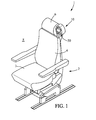
- Figure 1 shows a breathing assembly 1 comprising a storage unit 10, a breathing mask 50 and a seat 2.
- the seat comprises a seat cushion 3, a backrest 4 and a headrest 6.
- the user of the breathing assembly 1, preferably an aircraft crewmember and usually the pilot, is intended to seat on the seat 2.
- the storage unit 10 has a substantially vertical back wall 18 having holes receiving screws (not represented) maintaining the storage unit 10 on the top of the backrest 4 and next to the headrest 6.
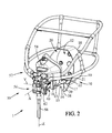
- the storage unit 10 further comprises a peripheral wall 19.
- the storage unit forms a cup having a receptacle 12 delimited by the back wall 18 and the peripheral wall 19.
- the storage unit 10 has an opening 20 opposite the back wall 18 for inserting the breathing mask 30 into the receptacle 12 and extracting the breathing mask 30 from the receptacle 12.
- the peripheral wall 19 includes a guiding plate 14 and two bevelled lateral walls 16, 17.
- the guiding plate 14 is flat, has a substantially constant thickness and extends substantially perpendicularly to an elevation direction Z which is substantially vertical.
- the guiding plate 14 has an upper surface 13 and a lower surface 15.
- the storage unit 10 further has a separate transversal beam 30 extending in a transversal direction Y perpendicular to the elevation direction Z.
- the transversal beam 30 is fixed to the guiding plate 14 by screws 32.
- pins 21, 22 are fixed to the transversal beam 30.
- the pins 21, 22 extend along a sliding direction X perpendicular to the transversal direction Y and to the elevation direction Z.
- Each of the pins 21, 22 comprises a cylindrical retaining portion 21 a, 22a tight fitted, and preferably press fitted, into a respective cylindrical bore of the transversal beam 30.
- the peripheral wall 19 of the storage unit 10 further has a notch 34 extending along the elevation direction Z and a protruding portion 38 which delimits the notch 34 in the sliding direction X.
- the breathing mask 50 has an oronasal face piece 54, an on-demand regulator 56 and a harness 52.
- the oronasal face piece 54 is intended to be placed on the face of the user, in communication with the nose and the mouth of the user in order to provide breathing gas for the user.
- the on-demand regulator 56 controls the flow of breathing gas provided to the user in accordance with the breath of the user.
- the on-demand regulator 56 also controls the concentration in oxygen of the breathing gas provided to the user through the oronasal face piece 54.
- the on-demand regulator 56 is provided with oxygen from a pressurised source (not represented) through a supply duct 58.
- the breathing mask 50 could be a full-face mask and therefore include an eye protection.
- the harness 52 is intended to press the oronasal face piece 54 on the user face in order to maintain the oronasal face piece 54.
- the breathing mask 50 is intended to be received in the receptacle 12 of the storage unit 10 and firmly maintained in a storage position.
- the on-demand regulator 56 includes a rigid casing 40 and a lever 62.
- the rigid casing forms housing and defines a support 40 which has a proximal (front) end 40a and a distal (back) end 40b along the sliding direction X.
- the proximal end 40a can be caught by the user and is therefore outside the receptacle 12 or near the opening 20 whereas the distal end 40b is at the back of the receptacle 12.
- the lever 62 is mounted on the support 40 proximate the proximal end 40a and is movable relative to the support 40 between a secure state and release state by rotation around a release axis 70 parallel to the sliding direction X, as shown in particular in figures 6 and 7 .
- the lever 62 is biased towards the secure state by a spring (not represented).
- the harness 52 is provided with pressurised oxygen from the source, so that the harness 52 is inflated.
- the harness 52 is no more in communication with the source of oxygen and consequently deflates, at least partially. This function of the lever is well known and thus will not be described in details.
- the oronasal face piece 54 is rigidly maintained on the support 40 which is slidingly mounted on the storage unit 10 between the storage position and an exit position.
- the support 40 has a lower surface 39. Between the storage position and the exit position, the lower surface 39 of the support 40 rests on the upper surface 13 of the guiding plate 14. Moreover, the support 40 has an optional retaining element 48 comprising two transversal wings 48a, 48b which protrude from the lower surface 39. The wings of the retaining element 48 extend through a slot 11 in the guiding plate 40 and face the lower surface 15 of the guiding plate 14. Therefore, the retaining element 48 and the guiding plate 14 guide the support 40 in its sliding movement towards the storage position. It should be noticed that the slot 11 split the guiding plate 14, and in particular the upper surface 13 of the guiding plate 14 in two portions 13a, 13b.
- the support 40 has two bevelled lateral walls 45, 46 facing and parallel to the respective bevelled lateral walls 16, 17 of the storage unit 10 and furthermore the retaining element 48 extends in a substantially rectilinear portion of the slot 11 of the guiding plate 14.
- the lateral walls 45, 46 extend substantially perpendicularly to the transversal direction Y, but slightly angled so that lateral walls 45, 46 converge one towards the other towards the distal end 40b of the support 40. So, between the storage position and the exit position, the support 40 is substantially prevented from translating along the transversal direction Y and from rotation around the elevation direction Z relative to the storage unit 10.
- the breathing mask 50 and in particular the support 40, is guided in translation along the sliding direction X along a distance D between the storage position and the exit position.
- the lower surface 39 of the support is away from the guiding plate 14, so that the support is not slidingly mounted on the storage unit 10 anymore.
- the bevelled lateral wall 45 of the support 40 gets closer to the bevelled lateral wall 16 of the storage unit 10 and the bevelled lateral wall 46 of the support 40 gets closer to the bevelled lateral wall 17 of the storage unit 10, so translation of support 40 relative to the storage unit 10 along the transversal direction Y is progressively restricted.
- the lateral walls 45, 46 of the support 40 are substantially in contact with the respective lateral walls 16, 17 of the storage unit 10.
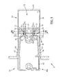
- the support 40 is close to the transversal beam 30 and further has a first hole 41 and a second hole 42 extending in the sliding the sliding direction X.
- the first pin 21 of the storage unit 10 is inserted in the first hole 41 of the support 40 and the second pin 22 of the storage unit 10 is inserted in the second hole 42 of the support 40.
- the first pin 21 in the storage position, has a first length l 21 inserted through the hole 41 and the second pin 22 has a second length l 22 inserted through the hole 42.
- the first length l 21 is preferably between 1 millimetre and 3 millimetres higher than the second length l 22 .
- the first length l 21 is about 6 millimetres and the second length l 22 is about 4 millimetres, and the distance D between the storage position and the exit position is about 40 millimetres.
- Each of the first pin 21 and the second pin 22 has a cylindrical portion 23, 26, a conical portion 24, 27 and a tip 25, 28.
- Each of the first hole 41 and the second hole 42 has a cylindrical portion 43, 44 and a bevelled edge extending in the sliding direction X. In the storage position, the cylindrical portion 43 of the first hole 41 surrounds the cylindrical portion 23 of the first pin 21 and the cylindrical portion 44 of the second hole 42 surrounds the cylindrical portion 24 of the second pin 22.
- the cylindrical portion 23 of the first pin 21 has a first circular external section S 21
- the cylindrical portion 24 of the second pin 22 has a second circular external section S 22
- the cylindrical portion 43 of the first hole 41 has a first internal section S 41
- the cylindrical portion 44 of the second hole 42 has a second circular internal section S 42 .
- the diameter of the first external section S 21 and the diameter of the second external section S 22 are preferably close to 3 millimetres.
- the clearance 74 between the diameter of the second external section S 22 and the diameter of the second internal section S 42 is preferably between 0.01 millimetre and 0.5 millimetre.
- the clearance 72 between the first external section S 21 and the diameter of the first internal section S 41 is preferably between 0.01 millimetre and 0.5 millimetre along the elevation direction Z and between 0.5 millimetre and 2 millimetres along the transversal direction. More accurately, the first internal section S 41 is oblong and elongated along the transversal direction Y. In the elevation direction Z, the first internal section S 41 is preferably between 0.01 millimetre and 0.5 millimetre greater than the diameter of the first external section S 21 whereas in the transversal direction Y, the first internal section S 41 is preferably between 0.5 millimetre and 2 millimetres greater than the diameter of the first external section S 21 .
- the pins 21, 22 are in metallic material, preferably in steel, and the support 40, at least the holes 41, 42, is in plastic material, preferably in polypropylene.
- the breathing mask 50 is retained in the storage position by a releasable securing device 60 disposed near the proximal end 40a of the support 40.
- the securing device 60 includes the lever 62 and the protruding portion 38.
- a lateral abutment portion 64 of the lever 62 is inserted in the notch 34.
- the lateral abutment portion 64 of the lever 62 has a surface extending substantially perpendicularly to the sliding direction X and facing a surface of the protruding portion 38 of the storage unit 10 extending substantially perpendicularly to the sliding direction X. Therefore, the support 40 is prevented from translating relative to the storage unit 10 along the sliding direction X towards the exit position by abutment of the abutment portion 64 of the lever 62 against the protruding portion 38 of the storage unit 10, when the lever 62 is in the secure state.
- the abutment portion 64 of the lever 62 has a lateral edge 66 having a length L 66 (referenced in figure 7 ) and being substantially vertical in the secure state.
- the protruding portion 38 of the storage unit 10 has a lateral edge 36, substantially vertical, having a length L 36 (referenced in figure 7 ).
- the length L 66 of the lateral edge 66 is preferably about 30 millimetres whereas the length L 36 of the lateral edge 36 is preferably about 10 millimetres.
- the lateral edge 66 of the lever 62 is substantially parallel to the lateral edge 36 of the storage unit 10 and the distance between the lateral edge 66 of the lever 62 and the lateral edge 36 of the storage unit 10 is substantially 4 millimetres.
- the surface of contact between the abutment portion 64 of the lever 62 and the protruding portion 38 of the storage unit 10 is substantially a rectangle having short sides of about 4 millimetres extending along the transversal direction and long sides of 10 millimetres along the elevation direction Z, said rectangle being distant from the release axis 70 of more than 20 millimetres, preferably substantially 40 millimetres.
- the lever 62 further as a bottom abutment portion 68 with extends substantially perpendicularly to the elevation direction Z and, in the secure state, the bottom abutment portion 68 of the lever faces a bottom abutment surface 37 of the protrusion 38 extending substantially perpendicularly to the elevation direction Z. Therefore, when the lever is in the secure state, the lower surface 39 of the support 40 is substantially maintained is contact with the upper surface 13 of the guiding plate, at the proximal end 40a, and the support 40 is prevented from translating relative to the storage unit 10 along the elevation direction Z.
- the breathing mask 50 is also prevented from translation along the elevation direction Z, from rotation around the sliding direction X and from rotation around the transversal direction Y relative to the storage unit 10, because the lower surface 39 of the support 40 rests on the upper surface 13 of the guiding plate.
- the bottom abutment portion 68 of the lever 62 is away from the bottom abutment surface 37 of the protrusion 38 along the elevation direction Z.
- Figures 8 to 10 show a second embodiment 101 of breathing assembly in accordance with the invention.
- the elements which are identical in the first embodiment and in the second embodiment have their referenced unchanged.
- the elements of the second embodiment which are different but have a similar or identical function as in the first embodiment have a referenced increased by 100.
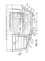
- the breathing assembly 101 essentially differs from the breathing assembly 1 in that the support 140 of the on-demand regulator 156 of the breathing mask 140 has two protrusions 141, 142 instead of the holes 41, 42 and the storage cup 110 has two slots 121, 122 instead of two pins 21, 22.
- the protrusions 141, 142 protrude from the lateral walls 45, 46 along the transversal direction Y, in opposite directions, proximate the distal end 140b of the support 140.
- the lower surface 139 of the support 140 rests on the two portions 113a, 113b of the upper surface 113 of the guiding plate 114, the protrusions 141, 142 are received in the slots 121, 122 and the protrusion 141, 142 face respective maintaining surfaces 176 (only one is represented) of the storage cup 110 along the elevation direction Z.
- the maintaining surfaces 176 delimit the top of the slots 121, 122.
- a small (non null) clearance 174 having a thickness e between 0.1 millimetre and 0.5 millimetre above the protrusions 141, 142, between the protrusions 141, 142 and the respective maintaining surfaces 176 along the elevation direction Z.
- the support 140 is maintained along the elevation direction Z at the distal end 140b (with a very low play), even in case of high acceleration/deceleration, the lower surface 139 of the support being maintained in contact of the upper surface 113 of the guiding plate 114 thanks to the protrusion 141, 142 engaging the slots 121, 122.
- each of the protrusions 141, 142 faces the respective maintaining surface 176 delimiting the top of the respective slot 121, 122 along a length l 121 , l 122 along the sliding direction X.
- said length l 121 , l 122 is close to 9 millimeters.
- the length l 121 and the length l 122 could differ a bit, as the length l 21 and the length l 22 of the breathing assembly1.
- the lower surface 139 of the support 140 slides in contact with the upper surface 113 of the guiding plate 114 along a distance D along the sliding direction X, between the storage position and the exit position, preferably close to 40 millimetres.
- the breathing assembly 101 comprises two grooves 148a, 148b instead of the retaining element 48 of the breathing assembly 101, in order to guide the support 140 from the exit position towards the storage position, the protrusion 141, 142 engaging the grooves 148a, 148b and then engaging the slots 121, 122.
- the breathing assembly 101 differs from the breathing assembly 1 in that it further comprises a rigid bridge 109 extending along the transversal direction Y and connecting the two portions 113a, 113b of the upper surface 113 of the guiding plate 114 for strengthening the guiding plate 114 at the proximal end 140a.
- the bridge 109 includes ribs.
- the support 140 is prevented from sliding along the sliding direction X and from moving away from upper surface 113 of the guiding plate 114 along the elevation direction Z at the proximal end 140a by abutment of the lever 62 against the protrusion 38.
- the scope of the invention is not limited to the above described embodiment shown for illustrative purpose.
- the lever 62 may be slidingly mounted on the support 40 instead of being rotatively mounted on the support 40.
- the release securing device 60 could for instance comprise an electro-magnet releasably retaining the breathing mask 50 in the storage position.
Landscapes
- Health & Medical Sciences (AREA)
- Pulmonology (AREA)
- General Health & Medical Sciences (AREA)
- Business, Economics & Management (AREA)
- Emergency Management (AREA)
- Engineering & Computer Science (AREA)
- Aviation & Aerospace Engineering (AREA)
- Respiratory Apparatuses And Protective Means (AREA)
- Preparing Plates And Mask In Photomechanical Process (AREA)
Claims (22)
- Ensemble respiratoire (1, 101) pour aéronef, comprenant :- une unité de stockage (10, 110) destinée à être fixée à l'aéronef, comportant un réceptacle (12) et une ouverture (20), l'unité de stockage (10, 110) comportant en outre une surface de guidage (13, 113) s'étendant perpendiculairement à une direction d'élévation (Z),- un masque respiratoire (50, 150) destiné à être mis par un membre d'équipage d'aéronef, le masque respiratoire (50, 150) comprenant un support rigide (40, 140) ayant une surface de coulissement (39, 139) adaptée pour coulisser en contact avec la surface de guidage (13, 113) de l'unité de stockage (10, 110), suivant une direction de coulissement (X), entre une position de stockage et une position de sortie, la direction de coulissement (X) étant perpendiculaire à la direction d'élévation (Z), le support (40, 140) s'étend suivant la direction de coulissement (X) entre une extrémité proximale (40a, 140a) et une extrémité distale (40b, 140b), et- un dispositif de fixation libérable (60) possédant un état de fixation et un état de libération, dans lequel, lorsqu'il est dans l'état de fixation, le dispositif de fixation (60) empêche le support (40, 140) de coulisser à partir de la position de stockage vers la position de sortie et, lorsqu'il est dans l'état de libération, le dispositif de fixation (60) permet au support (40, 140) de coulisser à partir de la position de stockage vers la position de sortie, dans lequel :- le support (40, 140) comporte en outre au moins un élément de maintien (41, 42 ; 141, 142) disposé à l'extrémité distale (40b, 140b) du support suivant la direction de coulissement (X),- l'unité de stockage (10) comporte en outre un élément de maintien (21, 22 ; 121, 122),- dans la position de stockage, la surface de coulissement (39, 139) du support (40, 140) est empêchée de s'éloigner de la surface de guidage (13, 113) de l'unité de stockage (10, 110) suivant la direction d'élévation (Z) à l'extrémité distale (40b, 140b) par coopération de l'élément de maintien (41, 42 ; 141, 142) du support (40, 140) avec l'élément de maintien (21, 22 ; 121, 122) de l'unité de stockage (10, 110).
- Ensemble respiratoire selon la revendication 1, dans lequel l'élément de maintien (41, 42 ; 141, 142) du support (40, 140) coopère avec l'élément de maintien (21, 22 ; 121, 122) de l'unité de stockage (10, 110) sur une longueur de maintien (l21, l22 ; l121, l122) suivant la direction de coulissement (X), et la position de stockage est espacée de la position de sortie d'une distance (D) au moins trois fois plus longue que ladite longueur de maintien (l21, l22 ; l121, l122).
- Ensemble respiratoire selon la revendication 2, dans lequel la longueur de maintien (l21, l22 ; l121, l122) est inférieure à 15 millimètres, de préférence inférieure à 10 millimètres.
- Ensemble respiratoire selon une quelconque des revendications précédentes, dans lequel dans la position de stockage, un espace libre (72, 74 ; 174) inférieur à 0,5 millimètre, de préférence inférieur à 0,1 millimètre, suivant la direction d'élévation (Z), est placé entre l'élément de maintien (41, 42 ; 141, 142) du support (40, 140) et l'élément de maintien (21, 22 ; 121, 122) de l'unité de stockage (10).
- Ensemble respiratoire selon une quelconque des revendications précédentes, dans lequel :- le dispositif de fixation (60) comprend un levier (62) et une partie saillante (38), et- dans la position de stockage du support (40, 140) et dans l'état de fixation du dispositif de fixation (60), le levier (62) comporte une partie de butée (64) qui vient en butée contre la partie saillante (38) suivant la direction de coulissement (X).
- Ensemble respiratoire selon la revendication 5, dans lequel, dans la position de stockage du support (40, 140) et dans l'état de fixation du dispositif de fixation (60), la surface de coulissement (39, 139) du support (40, 140) est empêchée de s'éloigner de la surface de guidage (13, 113) de l'unité de stockage (10, 110) suivant la direction d'élévation (Z) à l'extrémité proximale (40a, 140a) par coopération de la partie saillante (37, 38) avec le levier (62, 68).
- Ensemble respiratoire selon la revendication 5 ou la revendication 6, dans lequel :- la partie de butée (64) du levier (62) comporte un bord (66) s'étendant de façon sensiblement parallèle à un bord (36) de la partie saillante (38),- dans l'état de fixation du dispositif de fixation (60), suivant la direction de coulissement (X), le bord (66) de la partie de butée (64) du levier (62) fait face à la partie saillante (38) et le bord (36) de la partie saillante (38) fait face à la partie de butée (64) du levier (62),- dans l'état de fixation du dispositif de fixation (60), en section transversale perpendiculaire à la direction de coulissement (X), tout le bord (66) de la partie de butée (64) du levier (62) est séparé (d) d'au moins 1 millimètre du bord (36) de la partie saillante (38).
- Ensemble respiratoire selon la revendication 7, dans lequel le bord (66) de la partie de butée (64) du levier (62) possède une longueur (L66) au moins deux fois plus longue que la longueur (L36) du bord (36) de la partie saillante (38).
- Ensemble respiratoire selon une quelconque des revendications 5 à 8, dans lequel le levier (62) est monté de façon pivotante sur le support (40, 140) autour d'un axe de libération (70) parallèle à la direction de coulissement (X), et la partie saillante (38) est fixée à l'unité de stockage (10, 110).
- Ensemble respiratoire selon une quelconque des revendications 5 à 9, dans lequel le masque respiratoire (50, 150) comporte un harnais (52) et le levier (62) génère le gonflage du harnais (52) lorsque le levier (62) est dans l'état de libération.
- Ensemble respiratoire selon une quelconque des revendications précédentes, dans lequel la surface de guidage (113) de la coupelle de stockage (10, 110) comprend deux parties distantes (113a, 113b) raccordées l'une à l'autre par l'intermédiaire d'un pont rigide (109).
- Ensemble respiratoire selon une quelconque des revendications précédentes, dans lequel un parmi l'élément de maintien (121, 122) de l'unité de stockage (110) et l'élément de maintien (141, 142) du support (140) est une fente (121, 122) s'étendant dans la direction de coulissement (X) et l'autre est une saillie (141, 142) faisant saillie dans une direction transversale (Y) perpendiculaire à la direction de coulissement (X) et à la direction d'élévation (Z), la saillie (141, 142) coopérant avec la rainure (121, 122) dans la position de stockage.
- Ensemble respiratoire selon the la revendication 12, dans lequel :- l'ensemble respiratoire (101) comprend au moins :- deux saillies : une première saillie (141) et une seconde saillie (142) faisant saillie suivant la direction transversale (Y) dans des sens opposés, et- deux fentes : une première fente (121) et une seconde fente (122) et,- dans la position de stockage, la première saillie (141) coopère avec la première fente (121) et la seconde saillie (142) coopère avec la seconde fente (122),- dans la position de sortie, la première saillie (141) s'étend à l'écart de la première fente (121) et la seconde saillie (142) s'étend à l'écart de la seconde fente (122).
- Ensemble respiratoire selon une quelconque des revendications 1 à 11, dans lequel un parmi l'élément de maintien (21, 22) de l'unité de stockage (10) et l'élément de maintien (41, 42) du support (40) est une broche (21, 22) s'étendant dans la direction de coulissement (X) et l'autre est un trou (41, 42), et la broche (21, 22) est insérée dans ledit trou (41, 42) lorsque le support rigide (40) est dans la position de stockage.
- Ensemble respiratoire selon la revendication 14, dans lequel :- l'ensemble respiratoire (1) comprend au moins :- deux broches : une première broche (21) et une seconde broche (22) et,- deux trous : un premier trou (41) et un second trou (42), et- dans la position de stockage, la première broche (21) s'étend à travers le premier trou (41) et la seconde broche (22) s'étend à travers le second trou (42),- dans la position de sortie, la première broche (21) s'étend à l'écart du premier trou (41) et la seconde broche (22) s'étend à l'écart du second trou (42).
- Ensemble respiratoire selon la revendication 15, dans lequel :- dans la position de stockage, la première broche (21) a une première longueur (l21) s'étendant à travers le premier trou (41) et la seconde broche (22) a une seconde longueur (122) s'étendant à travers le second trou (42), et- la première longueur (l21) est au moins dix pour cent plus longue que la seconde longueur (122).
- Ensemble respiratoire selon la revendication 15 ou la revendication 16, dans lequel :- la première broche (21) a une première section externe (S21), le premier trou (41) a une première section interne (S41), et- la seconde broche (22) a une seconde section externe (S22) qui est circulaire, le second trou (42) a une seconde section interne (S42) qui est (oblongue et) allongée suivant une direction transversale (Y) perpendiculaire à la direction de coulissement (X) et à la direction d'élévation (Z).
- Ensemble respiratoire selon une quelconque des revendications 14 à 17, dans lequel :- la broche (21, 22) comporte une partie cylindrique (23, 26), une extrémité (25, 28) et une partie conique (24, 27) s'étendant entre la partie cylindrique (23, 26) et l'extrémité (25, 28), et- le trou (41, 42) comporte une partie cylindrique (43, 44) entourant la partie cylindrique (23, 26) de la broche (21, 22) lorsque le support est dans la position de stockage.
- Ensemble respiratoire selon une quelconque des revendications 14 à 18, dans lequel la broche (21, 22) est en matériau métallique et le support (40) est en matériau plastique.
- Ensemble respiratoire selon une quelconque des revendications 14 à 19, dans lequel la broche (21, 22) est ajustée de façon serrée dans une barre distincte (30) fixée à l'unité de stockage (10).
- Ensemble respiratoire selon une quelconque des revendications précédentes, dans lequel :- le support (40) comporte en outre deux parois latérales biseautées (45, 46) disposées sur des côtés opposés du support (40, 140) suivant une direction transversale (Y) perpendiculaire à la direction de coulissement (X) et à la direction d'élévation (Z),- l'unité de stockage (10) comporte en outre deux parois latérales biseautées respectives (16, 17), et- dans la position de stockage, les parois latérales biseautées (45, 46) du support (40) sont parallèles aux, et sensiblement en contact avec les, parois latérales biseautées respectives (16, 17) de l'unité de stockage (10).
- Ensemble respiratoire selon une quelconque des revendications précédentes, comprenant en outre un siège (2) et dans lequel l'unité de stockage (10) est fixée au siège (2).
Applications Claiming Priority (1)
| Application Number | Priority Date | Filing Date | Title |
|---|---|---|---|
| PCT/IB2010/003511 WO2012085616A1 (fr) | 2010-12-23 | 2010-12-23 | Ensemble respiratoire pour avion avec dispositif renforcé de fixation du masque |
Publications (2)
| Publication Number | Publication Date |
|---|---|
| EP2654905A1 EP2654905A1 (fr) | 2013-10-30 |
| EP2654905B1 true EP2654905B1 (fr) | 2014-12-10 |
Family
ID=44534819
Family Applications (1)
| Application Number | Title | Priority Date | Filing Date |
|---|---|---|---|
| EP10819706.2A Not-in-force EP2654905B1 (fr) | 2010-12-23 | 2010-12-23 | Ensemble respiratoire pour avion avec dispositif renforcé de fixation du masque |
Country Status (6)
| Country | Link |
|---|---|
| US (1) | US9526927B2 (fr) |
| EP (1) | EP2654905B1 (fr) |
| CN (1) | CN103260707B (fr) |
| BR (1) | BR112013010509B1 (fr) |
| CA (1) | CA2816006C (fr) |
| WO (1) | WO2012085616A1 (fr) |
Families Citing this family (7)
| Publication number | Priority date | Publication date | Assignee | Title |
|---|---|---|---|---|
| BR112016025177B1 (pt) * | 2014-05-20 | 2021-02-02 | Zodiac Aerotechnics | sistema de respiração e assento para membro da tripulação ou passageiro de aeronave |
| WO2016113584A1 (fr) * | 2015-01-15 | 2016-07-21 | Zodiac Aerotechnics | Dispositif de rangement d'équipement d'urgence pour membre d'équipage d'avion |
| WO2017055888A1 (fr) * | 2015-09-29 | 2017-04-06 | Zodiac Aerotechnics | Équipement d'urgence pour un aéronef comprenant un masque respiratoire |
| CN108136234B (zh) | 2015-09-29 | 2020-08-11 | 佐迪埃克航空技术公司 | 飞机驾驶舱、包括呼吸面罩和储存装置的组件以及这种组件的储存方法和使用方法 |
| WO2019008446A1 (fr) * | 2017-07-05 | 2019-01-10 | Zodiac Aerotechnics | Système de masque respiratoire confortable à enfilage rapide pour pilote d'aéronef |
| FR3072298B1 (fr) * | 2017-10-17 | 2021-07-09 | Zodiac Aerotechnics | Masque respiratoire pour aeronef et procede de mise en position repliee d'un masque respiratoire pour son rangement dans une unite de rangement. |
| US12377297B2 (en) * | 2019-02-18 | 2025-08-05 | Safran Aerotechnics | Breathing equipment for an aircraft, breathing assembly and method for stowing the breathing equipment |
Family Cites Families (10)
| Publication number | Priority date | Publication date | Assignee | Title |
|---|---|---|---|---|
| US4154237A (en) * | 1977-12-27 | 1979-05-15 | Boeing Commercial Airplane Company | Passenger emergency oxygen mask drop zone extender |
| US4803980A (en) * | 1986-10-20 | 1989-02-14 | Conax Florida Corporation | Automatic breathing mask release mechanism |
| US4909247A (en) * | 1988-05-06 | 1990-03-20 | Figgie International, Inc. | Aircraft emergency breathing assembly |
| WO1990002582A1 (fr) * | 1988-09-14 | 1990-03-22 | Puritan-Bennett Corporation | Masque a oxygene pour personnel d'equipage et unite de rangement de tuyau souple |
| FR2752165B1 (fr) * | 1996-08-12 | 1998-10-09 | Intertechnique Sa | Equipement de protection respiratoire a mise en place rapide |
| WO1999007442A2 (fr) * | 1997-08-10 | 1999-02-18 | Wible Dan S | Systeme de plongee a circuit ferme, muni de boitiers interchangeables de conditionnement de gaz et destine a l'usage personnel |
| US6526967B2 (en) * | 2001-06-11 | 2003-03-04 | Be Intellectual Property, Inc. | Crew oxygen mask stowage assembly including selective depressurization valve |
| DE102004026649A1 (de) * | 2004-06-01 | 2006-01-05 | DRäGER AEROSPACE GMBH | Sauerstoffnotversorgungseinrichtung |
| US8863744B2 (en) | 2007-07-10 | 2014-10-21 | Zodiac Aerotechnics | Stowage box for breathing mask |
| WO2012025862A1 (fr) * | 2010-08-26 | 2012-03-01 | Koninklijke Philips Electronics N.V. | Système de stockage de dispositif d'interface patient |
-
2010
- 2010-12-23 EP EP10819706.2A patent/EP2654905B1/fr not_active Not-in-force
- 2010-12-23 BR BR112013010509-7A patent/BR112013010509B1/pt not_active IP Right Cessation
- 2010-12-23 US US13/881,393 patent/US9526927B2/en not_active Expired - Fee Related
- 2010-12-23 CN CN201080070931.9A patent/CN103260707B/zh not_active Expired - Fee Related
- 2010-12-23 WO PCT/IB2010/003511 patent/WO2012085616A1/fr not_active Ceased
- 2010-12-23 CA CA2816006A patent/CA2816006C/fr not_active Expired - Fee Related
Also Published As
| Publication number | Publication date |
|---|---|
| CA2816006A1 (fr) | 2012-06-28 |
| WO2012085616A1 (fr) | 2012-06-28 |
| US20130213403A1 (en) | 2013-08-22 |
| BR112013010509B1 (pt) | 2019-08-06 |
| CN103260707A (zh) | 2013-08-21 |
| US9526927B2 (en) | 2016-12-27 |
| BR112013010509A2 (pt) | 2016-08-02 |
| CA2816006C (fr) | 2017-09-26 |
| CN103260707B (zh) | 2016-08-10 |
| EP2654905A1 (fr) | 2013-10-30 |
Similar Documents
| Publication | Publication Date | Title |
|---|---|---|
| EP2654905B1 (fr) | Ensemble respiratoire pour avion avec dispositif renforcé de fixation du masque | |
| US8898910B2 (en) | Cutter | |
| EP2012613B1 (fr) | Boucle a declenchement rapide | |
| EP2892697B1 (fr) | Rasoir | |
| EP2752275B1 (fr) | Instrument tranchant | |
| US11668127B2 (en) | Aircraft door mechanism, and associated aircraft and moving method | |
| EP2211996B1 (fr) | Masque respiratoire à réduction de consommation d'oxygène | |
| US10376719B1 (en) | Vehicle-mounted multifunctional tool | |
| US20180361179A1 (en) | Respiratory equipment for aircraft, with inflatable mask and harness, and its storage space | |
| US20100213317A1 (en) | Door hinge and door arrangement | |
| US9241545B2 (en) | Buckle assembly | |
| EP2731680B1 (fr) | Agencement de dispositif de limitation de chute personnelle et agencement de liaison d'utilisateur associé | |
| US20150284096A1 (en) | Aircraft seat attachment system provided with a system for locking an activation lever and/or for maintaining a clamping force by friction | |
| US20110115267A1 (en) | Convertible juvenile vehicle seat | |
| JP6393093B2 (ja) | 飛翔体の滑走装置 | |
| WO2007009556A1 (fr) | Dispositif d'ouverture de secours pour un porte-bagages avec coque abaissable | |
| EP3064079A1 (fr) | Casque pour motocyclistes | |
| RU2722155C1 (ru) | Система защелки потолочного багажного отсека | |
| EP2525874B1 (fr) | Ensemble respiratoire pour aeronef | |
| US8926242B2 (en) | Device for securing a mobile device in an aircraft cabin | |
| US6474337B1 (en) | Universal oxygen mask bayonet and bayonet receiver deflector | |
| CN220518571U (zh) | 飞机座椅用的安全带以及座椅 | |
| KR20130115283A (ko) | 버클 및 버클 릴리스 시스템용 리테이닝 메커니즘 | |
| JP2010023750A (ja) | シートベルトガイド | |
| CN114851929B (zh) | 可拆卸侧撞保护装置及具有该可拆卸侧撞保护装置的儿童安全座椅 |
Legal Events
| Date | Code | Title | Description |
|---|---|---|---|
| PUAI | Public reference made under article 153(3) epc to a published international application that has entered the european phase |
Free format text: ORIGINAL CODE: 0009012 |
|
| 17P | Request for examination filed |
Effective date: 20130425 |
|
| AK | Designated contracting states |
Kind code of ref document: A1 Designated state(s): AL AT BE BG CH CY CZ DE DK EE ES FI FR GB GR HR HU IE IS IT LI LT LU LV MC MK MT NL NO PL PT RO RS SE SI SK SM TR |
|
| RAP1 | Party data changed (applicant data changed or rights of an application transferred) |
Owner name: ZODIAC AEROTECHNICS |
|
| DAX | Request for extension of the european patent (deleted) | ||
| GRAP | Despatch of communication of intention to grant a patent |
Free format text: ORIGINAL CODE: EPIDOSNIGR1 |
|
| INTG | Intention to grant announced |
Effective date: 20140919 |
|
| GRAS | Grant fee paid |
Free format text: ORIGINAL CODE: EPIDOSNIGR3 |
|
| GRAA | (expected) grant |
Free format text: ORIGINAL CODE: 0009210 |
|
| AK | Designated contracting states |
Kind code of ref document: B1 Designated state(s): AL AT BE BG CH CY CZ DE DK EE ES FI FR GB GR HR HU IE IS IT LI LT LU LV MC MK MT NL NO PL PT RO RS SE SI SK SM TR |
|
| REG | Reference to a national code |
Ref country code: GB Ref legal event code: FG4D |
|
| REG | Reference to a national code |
Ref country code: CH Ref legal event code: EP |
|
| REG | Reference to a national code |
Ref country code: IE Ref legal event code: FG4D |
|
| REG | Reference to a national code |
Ref country code: AT Ref legal event code: REF Ref document number: 700348 Country of ref document: AT Kind code of ref document: T Effective date: 20150115 |
|
| REG | Reference to a national code |
Ref country code: DE Ref legal event code: R096 Ref document number: 602010020950 Country of ref document: DE Effective date: 20150122 |
|
| REG | Reference to a national code |
Ref country code: AT Ref legal event code: MK05 Ref document number: 700348 Country of ref document: AT Kind code of ref document: T Effective date: 20141210 Ref country code: NL Ref legal event code: VDEP Effective date: 20141210 |
|
| REG | Reference to a national code |
Ref country code: NL Ref legal event code: VDEP Effective date: 20141210 |
|
| PG25 | Lapsed in a contracting state [announced via postgrant information from national office to epo] |
Ref country code: ES Free format text: LAPSE BECAUSE OF FAILURE TO SUBMIT A TRANSLATION OF THE DESCRIPTION OR TO PAY THE FEE WITHIN THE PRESCRIBED TIME-LIMIT Effective date: 20141210 Ref country code: NO Free format text: LAPSE BECAUSE OF FAILURE TO SUBMIT A TRANSLATION OF THE DESCRIPTION OR TO PAY THE FEE WITHIN THE PRESCRIBED TIME-LIMIT Effective date: 20150310 Ref country code: FI Free format text: LAPSE BECAUSE OF FAILURE TO SUBMIT A TRANSLATION OF THE DESCRIPTION OR TO PAY THE FEE WITHIN THE PRESCRIBED TIME-LIMIT Effective date: 20141210 Ref country code: LT Free format text: LAPSE BECAUSE OF FAILURE TO SUBMIT A TRANSLATION OF THE DESCRIPTION OR TO PAY THE FEE WITHIN THE PRESCRIBED TIME-LIMIT Effective date: 20141210 |
|
| REG | Reference to a national code |
Ref country code: LT Ref legal event code: MG4D |
|
| PG25 | Lapsed in a contracting state [announced via postgrant information from national office to epo] |
Ref country code: AT Free format text: LAPSE BECAUSE OF FAILURE TO SUBMIT A TRANSLATION OF THE DESCRIPTION OR TO PAY THE FEE WITHIN THE PRESCRIBED TIME-LIMIT Effective date: 20141210 Ref country code: HR Free format text: LAPSE BECAUSE OF FAILURE TO SUBMIT A TRANSLATION OF THE DESCRIPTION OR TO PAY THE FEE WITHIN THE PRESCRIBED TIME-LIMIT Effective date: 20141210 Ref country code: LV Free format text: LAPSE BECAUSE OF FAILURE TO SUBMIT A TRANSLATION OF THE DESCRIPTION OR TO PAY THE FEE WITHIN THE PRESCRIBED TIME-LIMIT Effective date: 20141210 Ref country code: GR Free format text: LAPSE BECAUSE OF FAILURE TO SUBMIT A TRANSLATION OF THE DESCRIPTION OR TO PAY THE FEE WITHIN THE PRESCRIBED TIME-LIMIT Effective date: 20150311 Ref country code: SE Free format text: LAPSE BECAUSE OF FAILURE TO SUBMIT A TRANSLATION OF THE DESCRIPTION OR TO PAY THE FEE WITHIN THE PRESCRIBED TIME-LIMIT Effective date: 20141210 Ref country code: RS Free format text: LAPSE BECAUSE OF FAILURE TO SUBMIT A TRANSLATION OF THE DESCRIPTION OR TO PAY THE FEE WITHIN THE PRESCRIBED TIME-LIMIT Effective date: 20141210 |
|
| PG25 | Lapsed in a contracting state [announced via postgrant information from national office to epo] |
Ref country code: BE Free format text: LAPSE BECAUSE OF NON-PAYMENT OF DUE FEES Effective date: 20141231 Ref country code: NL Free format text: LAPSE BECAUSE OF FAILURE TO SUBMIT A TRANSLATION OF THE DESCRIPTION OR TO PAY THE FEE WITHIN THE PRESCRIBED TIME-LIMIT Effective date: 20141210 |
|
| PG25 | Lapsed in a contracting state [announced via postgrant information from national office to epo] |
Ref country code: EE Free format text: LAPSE BECAUSE OF FAILURE TO SUBMIT A TRANSLATION OF THE DESCRIPTION OR TO PAY THE FEE WITHIN THE PRESCRIBED TIME-LIMIT Effective date: 20141210 Ref country code: RO Free format text: LAPSE BECAUSE OF FAILURE TO SUBMIT A TRANSLATION OF THE DESCRIPTION OR TO PAY THE FEE WITHIN THE PRESCRIBED TIME-LIMIT Effective date: 20141210 Ref country code: PT Free format text: LAPSE BECAUSE OF FAILURE TO SUBMIT A TRANSLATION OF THE DESCRIPTION OR TO PAY THE FEE WITHIN THE PRESCRIBED TIME-LIMIT Effective date: 20150410 Ref country code: CZ Free format text: LAPSE BECAUSE OF FAILURE TO SUBMIT A TRANSLATION OF THE DESCRIPTION OR TO PAY THE FEE WITHIN THE PRESCRIBED TIME-LIMIT Effective date: 20141210 Ref country code: SK Free format text: LAPSE BECAUSE OF FAILURE TO SUBMIT A TRANSLATION OF THE DESCRIPTION OR TO PAY THE FEE WITHIN THE PRESCRIBED TIME-LIMIT Effective date: 20141210 |
|
| REG | Reference to a national code |
Ref country code: CH Ref legal event code: PL |
|
| PG25 | Lapsed in a contracting state [announced via postgrant information from national office to epo] |
Ref country code: PL Free format text: LAPSE BECAUSE OF FAILURE TO SUBMIT A TRANSLATION OF THE DESCRIPTION OR TO PAY THE FEE WITHIN THE PRESCRIBED TIME-LIMIT Effective date: 20141210 Ref country code: IS Free format text: LAPSE BECAUSE OF FAILURE TO SUBMIT A TRANSLATION OF THE DESCRIPTION OR TO PAY THE FEE WITHIN THE PRESCRIBED TIME-LIMIT Effective date: 20150410 |
|
| REG | Reference to a national code |
Ref country code: DE Ref legal event code: R097 Ref document number: 602010020950 Country of ref document: DE |
|
| REG | Reference to a national code |
Ref country code: IE Ref legal event code: MM4A |
|
| PG25 | Lapsed in a contracting state [announced via postgrant information from national office to epo] |
Ref country code: MC Free format text: LAPSE BECAUSE OF FAILURE TO SUBMIT A TRANSLATION OF THE DESCRIPTION OR TO PAY THE FEE WITHIN THE PRESCRIBED TIME-LIMIT Effective date: 20141210 |
|
| PLBE | No opposition filed within time limit |
Free format text: ORIGINAL CODE: 0009261 |
|
| STAA | Information on the status of an ep patent application or granted ep patent |
Free format text: STATUS: NO OPPOSITION FILED WITHIN TIME LIMIT |
|
| PG25 | Lapsed in a contracting state [announced via postgrant information from national office to epo] |
Ref country code: DK Free format text: LAPSE BECAUSE OF FAILURE TO SUBMIT A TRANSLATION OF THE DESCRIPTION OR TO PAY THE FEE WITHIN THE PRESCRIBED TIME-LIMIT Effective date: 20141210 Ref country code: LI Free format text: LAPSE BECAUSE OF NON-PAYMENT OF DUE FEES Effective date: 20141231 Ref country code: CH Free format text: LAPSE BECAUSE OF NON-PAYMENT OF DUE FEES Effective date: 20141231 Ref country code: IE Free format text: LAPSE BECAUSE OF NON-PAYMENT OF DUE FEES Effective date: 20141223 |
|
| 26N | No opposition filed |
Effective date: 20150911 |
|
| GBPC | Gb: european patent ceased through non-payment of renewal fee |
Effective date: 20150310 |
|
| REG | Reference to a national code |
Ref country code: FR Ref legal event code: PLFP Year of fee payment: 6 |
|
| PG25 | Lapsed in a contracting state [announced via postgrant information from national office to epo] |
Ref country code: IT Free format text: LAPSE BECAUSE OF FAILURE TO SUBMIT A TRANSLATION OF THE DESCRIPTION OR TO PAY THE FEE WITHIN THE PRESCRIBED TIME-LIMIT Effective date: 20141210 |
|
| PG25 | Lapsed in a contracting state [announced via postgrant information from national office to epo] |
Ref country code: GB Free format text: LAPSE BECAUSE OF NON-PAYMENT OF DUE FEES Effective date: 20150310 |
|
| PG25 | Lapsed in a contracting state [announced via postgrant information from national office to epo] |
Ref country code: SI Free format text: LAPSE BECAUSE OF FAILURE TO SUBMIT A TRANSLATION OF THE DESCRIPTION OR TO PAY THE FEE WITHIN THE PRESCRIBED TIME-LIMIT Effective date: 20141210 |
|
| PG25 | Lapsed in a contracting state [announced via postgrant information from national office to epo] |
Ref country code: SM Free format text: LAPSE BECAUSE OF FAILURE TO SUBMIT A TRANSLATION OF THE DESCRIPTION OR TO PAY THE FEE WITHIN THE PRESCRIBED TIME-LIMIT Effective date: 20141210 |
|
| PG25 | Lapsed in a contracting state [announced via postgrant information from national office to epo] |
Ref country code: BE Free format text: LAPSE BECAUSE OF FAILURE TO SUBMIT A TRANSLATION OF THE DESCRIPTION OR TO PAY THE FEE WITHIN THE PRESCRIBED TIME-LIMIT Effective date: 20141210 |
|
| PG25 | Lapsed in a contracting state [announced via postgrant information from national office to epo] |
Ref country code: CY Free format text: LAPSE BECAUSE OF FAILURE TO SUBMIT A TRANSLATION OF THE DESCRIPTION OR TO PAY THE FEE WITHIN THE PRESCRIBED TIME-LIMIT Effective date: 20141210 Ref country code: BG Free format text: LAPSE BECAUSE OF FAILURE TO SUBMIT A TRANSLATION OF THE DESCRIPTION OR TO PAY THE FEE WITHIN THE PRESCRIBED TIME-LIMIT Effective date: 20141210 |
|
| PG25 | Lapsed in a contracting state [announced via postgrant information from national office to epo] |
Ref country code: HU Free format text: LAPSE BECAUSE OF FAILURE TO SUBMIT A TRANSLATION OF THE DESCRIPTION OR TO PAY THE FEE WITHIN THE PRESCRIBED TIME-LIMIT; INVALID AB INITIO Effective date: 20101223 Ref country code: TR Free format text: LAPSE BECAUSE OF FAILURE TO SUBMIT A TRANSLATION OF THE DESCRIPTION OR TO PAY THE FEE WITHIN THE PRESCRIBED TIME-LIMIT Effective date: 20141210 Ref country code: LU Free format text: LAPSE BECAUSE OF NON-PAYMENT OF DUE FEES Effective date: 20141223 Ref country code: MT Free format text: LAPSE BECAUSE OF FAILURE TO SUBMIT A TRANSLATION OF THE DESCRIPTION OR TO PAY THE FEE WITHIN THE PRESCRIBED TIME-LIMIT Effective date: 20141210 |
|
| REG | Reference to a national code |
Ref country code: FR Ref legal event code: PLFP Year of fee payment: 7 |
|
| REG | Reference to a national code |
Ref country code: FR Ref legal event code: PLFP Year of fee payment: 8 |
|
| PG25 | Lapsed in a contracting state [announced via postgrant information from national office to epo] |
Ref country code: MK Free format text: LAPSE BECAUSE OF FAILURE TO SUBMIT A TRANSLATION OF THE DESCRIPTION OR TO PAY THE FEE WITHIN THE PRESCRIBED TIME-LIMIT Effective date: 20141210 |
|
| REG | Reference to a national code |
Ref country code: FR Ref legal event code: PLFP Year of fee payment: 9 |
|
| PG25 | Lapsed in a contracting state [announced via postgrant information from national office to epo] |
Ref country code: AL Free format text: LAPSE BECAUSE OF FAILURE TO SUBMIT A TRANSLATION OF THE DESCRIPTION OR TO PAY THE FEE WITHIN THE PRESCRIBED TIME-LIMIT Effective date: 20141210 |
|
| PGFP | Annual fee paid to national office [announced via postgrant information from national office to epo] |
Ref country code: DE Payment date: 20191119 Year of fee payment: 10 |
|
| PGFP | Annual fee paid to national office [announced via postgrant information from national office to epo] |
Ref country code: FR Payment date: 20191029 Year of fee payment: 10 |
|
| REG | Reference to a national code |
Ref country code: DE Ref legal event code: R119 Ref document number: 602010020950 Country of ref document: DE |
|
| PG25 | Lapsed in a contracting state [announced via postgrant information from national office to epo] |
Ref country code: FR Free format text: LAPSE BECAUSE OF NON-PAYMENT OF DUE FEES Effective date: 20201231 |
|
| PG25 | Lapsed in a contracting state [announced via postgrant information from national office to epo] |
Ref country code: DE Free format text: LAPSE BECAUSE OF NON-PAYMENT OF DUE FEES Effective date: 20210701 |