EP2657047B1 - Akkordenspiraldeckschicht für einen Luftreifen - Google Patents
Akkordenspiraldeckschicht für einen Luftreifen Download PDFInfo
- Publication number
- EP2657047B1 EP2657047B1 EP13164826.3A EP13164826A EP2657047B1 EP 2657047 B1 EP2657047 B1 EP 2657047B1 EP 13164826 A EP13164826 A EP 13164826A EP 2657047 B1 EP2657047 B1 EP 2657047B1
- Authority
- EP
- European Patent Office
- Prior art keywords
- strip
- overlay
- pneumatic tire
- width
- central region
- Prior art date
- Legal status (The legal status is an assumption and is not a legal conclusion. Google has not performed a legal analysis and makes no representation as to the accuracy of the status listed.)
- Active
Links
Images

Classifications
-
- B—PERFORMING OPERATIONS; TRANSPORTING
- B60—VEHICLES IN GENERAL
- B60C—VEHICLE TYRES; TYRE INFLATION; TYRE CHANGING; CONNECTING VALVES TO INFLATABLE ELASTIC BODIES IN GENERAL; DEVICES OR ARRANGEMENTS RELATED TO TYRES
- B60C9/00—Reinforcements or ply arrangement of pneumatic tyres
- B60C9/18—Structure or arrangement of belts or breakers, crown-reinforcing or cushioning layers
-
- B—PERFORMING OPERATIONS; TRANSPORTING
- B60—VEHICLES IN GENERAL
- B60C—VEHICLE TYRES; TYRE INFLATION; TYRE CHANGING; CONNECTING VALVES TO INFLATABLE ELASTIC BODIES IN GENERAL; DEVICES OR ARRANGEMENTS RELATED TO TYRES
- B60C9/00—Reinforcements or ply arrangement of pneumatic tyres
- B60C9/18—Structure or arrangement of belts or breakers, crown-reinforcing or cushioning layers
- B60C9/20—Structure or arrangement of belts or breakers, crown-reinforcing or cushioning layers built-up from rubberised plies each having all cords arranged substantially parallel
- B60C9/22—Structure or arrangement of belts or breakers, crown-reinforcing or cushioning layers built-up from rubberised plies each having all cords arranged substantially parallel the plies being arranged with all cords disposed along the circumference of the tyre
- B60C9/2204—Structure or arrangement of belts or breakers, crown-reinforcing or cushioning layers built-up from rubberised plies each having all cords arranged substantially parallel the plies being arranged with all cords disposed along the circumference of the tyre obtained by circumferentially narrow strip winding
-
- B—PERFORMING OPERATIONS; TRANSPORTING
- B60—VEHICLES IN GENERAL
- B60C—VEHICLE TYRES; TYRE INFLATION; TYRE CHANGING; CONNECTING VALVES TO INFLATABLE ELASTIC BODIES IN GENERAL; DEVICES OR ARRANGEMENTS RELATED TO TYRES
- B60C9/00—Reinforcements or ply arrangement of pneumatic tyres
- B60C9/18—Structure or arrangement of belts or breakers, crown-reinforcing or cushioning layers
- B60C9/20—Structure or arrangement of belts or breakers, crown-reinforcing or cushioning layers built-up from rubberised plies each having all cords arranged substantially parallel
- B60C9/22—Structure or arrangement of belts or breakers, crown-reinforcing or cushioning layers built-up from rubberised plies each having all cords arranged substantially parallel the plies being arranged with all cords disposed along the circumference of the tyre
-
- B—PERFORMING OPERATIONS; TRANSPORTING
- B60—VEHICLES IN GENERAL
- B60C—VEHICLE TYRES; TYRE INFLATION; TYRE CHANGING; CONNECTING VALVES TO INFLATABLE ELASTIC BODIES IN GENERAL; DEVICES OR ARRANGEMENTS RELATED TO TYRES
- B60C9/00—Reinforcements or ply arrangement of pneumatic tyres
- B60C9/18—Structure or arrangement of belts or breakers, crown-reinforcing or cushioning layers
- B60C9/28—Structure or arrangement of belts or breakers, crown-reinforcing or cushioning layers characterised by the belt or breaker dimensions or curvature relative to carcass
-
- B—PERFORMING OPERATIONS; TRANSPORTING
- B60—VEHICLES IN GENERAL
- B60C—VEHICLE TYRES; TYRE INFLATION; TYRE CHANGING; CONNECTING VALVES TO INFLATABLE ELASTIC BODIES IN GENERAL; DEVICES OR ARRANGEMENTS RELATED TO TYRES
- B60C9/00—Reinforcements or ply arrangement of pneumatic tyres
- B60C9/18—Structure or arrangement of belts or breakers, crown-reinforcing or cushioning layers
- B60C9/20—Structure or arrangement of belts or breakers, crown-reinforcing or cushioning layers built-up from rubberised plies each having all cords arranged substantially parallel
- B60C9/22—Structure or arrangement of belts or breakers, crown-reinforcing or cushioning layers built-up from rubberised plies each having all cords arranged substantially parallel the plies being arranged with all cords disposed along the circumference of the tyre
- B60C2009/2219—Structure or arrangement of belts or breakers, crown-reinforcing or cushioning layers built-up from rubberised plies each having all cords arranged substantially parallel the plies being arranged with all cords disposed along the circumference of the tyre with a partial zero degree ply at the belt edges - edge band
-
- B—PERFORMING OPERATIONS; TRANSPORTING
- B60—VEHICLES IN GENERAL
- B60C—VEHICLE TYRES; TYRE INFLATION; TYRE CHANGING; CONNECTING VALVES TO INFLATABLE ELASTIC BODIES IN GENERAL; DEVICES OR ARRANGEMENTS RELATED TO TYRES
- B60C9/00—Reinforcements or ply arrangement of pneumatic tyres
- B60C9/18—Structure or arrangement of belts or breakers, crown-reinforcing or cushioning layers
- B60C9/20—Structure or arrangement of belts or breakers, crown-reinforcing or cushioning layers built-up from rubberised plies each having all cords arranged substantially parallel
- B60C9/22—Structure or arrangement of belts or breakers, crown-reinforcing or cushioning layers built-up from rubberised plies each having all cords arranged substantially parallel the plies being arranged with all cords disposed along the circumference of the tyre
- B60C2009/2252—Physical properties or dimension of the zero degree ply cords
- B60C2009/2266—Density of the cords in width direction
- B60C2009/2271—Density of the cords in width direction with variable density
-
- B—PERFORMING OPERATIONS; TRANSPORTING
- B60—VEHICLES IN GENERAL
- B60C—VEHICLE TYRES; TYRE INFLATION; TYRE CHANGING; CONNECTING VALVES TO INFLATABLE ELASTIC BODIES IN GENERAL; DEVICES OR ARRANGEMENTS RELATED TO TYRES
- B60C9/00—Reinforcements or ply arrangement of pneumatic tyres
- B60C9/18—Structure or arrangement of belts or breakers, crown-reinforcing or cushioning layers
- B60C9/20—Structure or arrangement of belts or breakers, crown-reinforcing or cushioning layers built-up from rubberised plies each having all cords arranged substantially parallel
- B60C9/2003—Structure or arrangement of belts or breakers, crown-reinforcing or cushioning layers built-up from rubberised plies each having all cords arranged substantially parallel characterised by the materials of the belt cords
- B60C9/2009—Structure or arrangement of belts or breakers, crown-reinforcing or cushioning layers built-up from rubberised plies each having all cords arranged substantially parallel characterised by the materials of the belt cords comprising plies of different materials
Definitions
- the present invention relates to a pneumatic tire and, more specifically, to an overlay ply for a pneumatic tire.
- a radial tire may be provided with a belt reinforcement comprising breaker plies and a band ply (or overlay), wherein the band cords may be generally laid in parallel with the circumferential direction of the tire and the breaker cords may be inclined with respect to the circumferential direction.
- Edge plies may be effective for increasing the hooping force at the breaker edges, and accordingly effective for preventing ply edge looseness and separation.
- Such a band ply may be formed by winding a ply material having the same width as its finishing width, around the carcass, and the ends of the ply may be overlapped at a predetermined length. Accordingly, thickness and rigidity may be increased at the overlap, and RRO (Radial Runout) may be increased, and further, the tire uniformity may be disturbed.
- RRO Random Runout
- a jointless band ply may be used by forming an edge ply at each edge of a breaker and winding a strip separately at each breaker edge. Since the number of the windings or turns in each band ply may be small and the both ends of the strip may be free, the wound strip may loosen and shift during a tire vulcanizing process by the increased cord tension, and accordingly the band ply may have an uneven thickness distribution to increase RRO and disturb tire uniformity.
- One conventional jointless band ply may comprise a strip wound spirally at regular pitches from one edge to the other edge of a breaker, while slightly overlapping the adjacent edges thereof. Accordingly, the hoop effect may not be increased at the breaker edge regions where a strong hooping force may be required.
- Another conventional band may have a double layered structure at the edge of a breaker similar to a band ply wherein a strip, including reinforcing cords of 1 to 20 in number may be wound, while traversing a breaker.
- the traversing direction may be changed at least twice wind the strip around a previously wound portion thereof. Therefore, the band ply may not obtain a dimensional accuracy and a positional accuracy, as well reducing productivity.
- Another conventional band ply may be a strip wound around a breaker wherein the strip may be overlapped. In a central region, the overlap may be 50% of the strip width and the overlap may be increased to 75% in side regions. Accordingly, the band ply may have a double layered structure even in the central region, which may result in an increase in the hooping force in the central region as well as a decrease in cornering stiffness. The tire weight may also increase.
- US-A-5,076,336 describes a tire in accordance with the preamble of claim 1.
- a tire with a similar overlay layer arrangement in also described in JP-A-2001-322405 .
- EP-A-0 455 454 describes a tire with an overlay layer made by winding a strip wherein the winding pitch of the strip at the axially outer sides of the overlay is about 50 % of the width of the strip.
- “Circumferential” means lines or directions extending along the perimeter of the surface of the annular tire parallel to the Equatorial Plane (EP) and perpendicular to the axial direction; it can also refer to the direction of the sets of adjacent circular curves whose radii define the axial curvature of the tread, as viewed in cross section.
- Core means one of the reinforcement strands which the reinforcement structures of the tire comprise.
- Equatorial plane means the plane perpendicular to the tire's axis of rotation and passing through the center of its tread; or the plane containing the circumferential centerline of the tread.
- “Lateral” means an axial direction.
- Ply means a cord-reinforced layer of rubber-coated radially deployed or otherwise parallel cords.
- Ring and radially are used to mean directions radially toward or away from the axis of rotation of the tire.
- Ring Ply Structure means the one or more carcass plies of which at least one ply has reinforcing cords oriented at an angle of between 65° and 90° with respect to the equatorial plane of the tire.
- the invention relates to a tire in accordance with claim 1.
- a first example pneumatic tire in accordance with the present invention includes a carcass extending between bead portions through sidewall portions and a tread portion and a belt reinforcement structure.
- the carcass has at least one ply of parallel cords extending proximately to bead cores of the bead portions.
- the belt reinforcement structure is disposed radially outside of the carcass and radially inside of the tread portion.
- the belt reinforcement structure includes an overlay or overlay ply.
- the overlay includes a strip of parallel cords wound spirally and circumferentially from a first axially outer side of the overlay ply to a second axially outer side of the overlay. The distance between corresponding parts of adjacent strip windings defines a winding pitch.
- the winding pitch of the strip changes in an axially inward direction of the pneumatic tire towards the equatorial plane of the pneumatic tire such that the winding pitch in a central region of the belt reinforcement structure is increased relative to respective first and second axially outer sides of the overlay on each side of the equatorial plane of the pneumatic tire.
- the winding pitch of the strip at both axially outer sides of the overlay is in a range from 55% to 233% a width of the strip.
- a width of the central region is in a range from 1/3 to 7/8 a width of the belt reinforcement structure.
- Spaces of 4 mm to 20 mm are formed in the central region between axially adjacent edges of the strip of the overlay.
- Spaces of 27% to 133% of the width of the strip are formed in the central region between the axially adjacent edges of the strip of the overlay.
- the winding pitch at both axially outer sides may be in a range from 55% to 85% of the width of the strip.
- the winding pitch at both axially outer sides may be in a range from 60% to 75% or 65% to 70% of the width of the strip.
- the winding pitch at both axially outer sides is in a range from 120% to 180% of the width of the strip.
- the width of the central region may be 33% to 83% a width of the belt reinforcement structure.
- spaces from 4 mm to 12 mm may be formed in the central region between axially adjacent edges of the strip of the overlay ply.
- spaces of 27% to 80% of the strip may be formed in the central region between the axially adjacent edges of the strip of the overlay ply.
- the belt reinforcement structure may comprise at least one breaker layer.
- the at least one breaker layer is disposed radially outside the carcass.
- the at least one breaker layer may comprise two plies of cords inclined with respect to the equatorial plane of the pneumatic tire such that cords in one ply cross cords in the other ply.
- the overlay ply is disposed radially outside of the breaker layer and the strip of parallel cords may be wound spirally and circumferentially around the breaker layer from about one axial edge of the breaker layer to about the other axial edge of the breaker layer.
- the overlay is disposed radially outside of the breaker layer and the strip of parallel cords may be wound spirally and circumferentially around the breaker layer from overhanging one axial edge of the breaker layer to overhanging the other axial edge of the breaker layer such that each axial edge of overlay is aligned proximate to a respective axial edge of the breaker layer.
- the width of the strip may be in a range from 9 mm to 27 mm.
- the winding pitch of the strip may change continuously from in an axially inward direction towards the equatorial plane of the pneumatic tire such that the winding pitch in a central region of the belt reinforcement structure is increased continuously compared to the respective first and second axially outer side to the equatorial plane of the pneumatic tire on each side of the equatorial plane.
- the winding pitch may form an accordion structure.
- the winding pitch of the strip may change in steps, from in an axially inward direction towards the equatorial plane of the pneumatic tire such that the winding pitch in a central region of the belt reinforcement structure is increased in steps compared to the respective first and second axially outer side to the equatorial plane of the pneumatic tire on each side of the equatorial plane.
- the thickness of the strip may be in the range from 0.5 mm to 1.1 mm.
- the winding pitch in the central region at the equatorial plane of the pneumatic tire may be about two times the winding pitch at the first and second axially outer side.
- the spirally and circumferentially wound strip may be a continuous spirally and circumferentially wound strip.
- a comparative example pneumatic tire includes a carcass extending between bead portions through sidewall portions and a tread portion and a belt reinforcement structure.
- the carcass has at least one ply of parallel cords extending proximate to bead cores of the bead portions.
- the belt reinforcement structure is disposed radially outside of the carcass and radially inside of the tread portion.
- the belt reinforcement structure includes an overlay or overlay ply and at least one breaker layer.
- the at least one breaker layer is disposed radially outside the carcass and radially inside the overlay.
- the at least one breaker layer includes two plies of cords inclined with respect to the equatorial plane of the pneumatic tire such that cords in one ply cross cords in the other ply.
- the overlay ply includes a strip of parallel cords wound spirally and circumferentially from a first axially outer side of the overlay to a second axially outer side of the overlay.
- the distance between corresponding parts of adjacent strip windings defines a winding pitch.
- the winding pitch of the strip changes in an axially inward direction of the pneumatic tire towards the equatorial plane of the pneumatic tire such that the winding pitch in a central region of the belt reinforcement structure is increased compared to the respective first and second axially outer sides of the overlay on each side of the equatorial plane.
- the winding pitch at both axially outer sides being in a range of from 55% to 85% of a width of the strip.
- the width of the central region is in a range of from 1/3 to 5/6 a width of the belt reinforcement structure. Spaces of 4 mm to 12 mm are formed in the central region between the axially adjacent edges of the strip of the overlay ply. Spaces of 27% to 80% of the width of the strip are formed in the central region between the axially adjacent edges of the strip of the overlay ply.
- a second example pneumatic tire in accordance with the present invention includes a carcass extending between bead portions through sidewall portions and a tread portion and a belt reinforcement structure.
- the carcass has at least one ply of parallel cords extending proximate to bead cores of the bead portions.
- the belt reinforcement structure is disposed radially outside of the carcass and radially inside of the tread portion.
- the belt reinforcement structure includes an overlay or overlay ply and at least one breaker layer.
- the at least one breaker layer is disposed radially outside the carcass and radially inside the overlay.
- the at least one breaker layer includes two plies of cords inclined with respect to the equatorial plane of the pneumatic tire such that cords in one ply cross cords in the other ply.
- the overlay includes a strip of parallel cords wound spirally and circumferentially from a first axially outer side of the overlay to a second axially outer side of the overlay. The distance between corresponding parts of adjacent strip defines a winding pitch. The winding pitch of the strip changes in an axially inward direction of the pneumatic tire towards the equatorial plane of the pneumatic tire such that the winding pitch in a central region of the belt reinforcement structure is increased compared to the respective first and second axially outer sides of the overlay on each side of the equatorial plane.
- the winding pitch at both axially outer sides being in a range from 120% to 180% of a width of the strip such that the strip at both axially outer sides does not overlap.
- the width of the central region is in a range of from 1/3 to 5/6 a width of the belt reinforcement structure. Spaces of 4 mm to 12 mm are formed in the central region between the axially adjacent edges of the strip of the overlay ply. Spaces of 27% to 80% of the width of the strip are formed in the central region between the axially adjacent edges of the strip of the overlay ply.
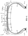
- a pneumatic tire 1 includes a pair of bead cores 5 disposed one in each bead portion 4 of the pneumatic tire, a carcass 6 extending between the bead portions through a tread portion 2 and sidewall portions 3 of the pneumatic tire and optionally turned up around the bead cores 5 from the inside to the outside of the pneumatic tire, and a belt reinforcement disposed between the carcass and the tread portion.
- the tread portion 2 is disposed radially outside the carcass 6.
- the belt reinforcement may include a breaker layer 7a, 7b disposed radially outside the carcass 6 and comprises an overlay or overlay ply 9, or band ply, disposed radially outside of the breaker layers 7a, 7b.
- the carcass 6 may include at least one ply of cords arranged radially at 70 to 90 degrees with respect to the equatorial plane EP of the pneumatic tire 1.
- These cords may be inorganic fiber cords, such as steel, glass, carbon, etc., or organic fiber cords, such as nylon, polyester, rayon, aromatic polyamide, aramid, etc.
- the breaker may include two plies 7a, 7b of parallel cords.
- the radially inner ply 7a may have an axial width close to the tread width between the edges a of the tread portion 2.
- the radially outer ply 7b may have a narrower width than the inner ply 7a.
- the inner ply 7a may include portions 10 projecting from the edges b of the outer ply 7b to the edges c of the inner ply 7a.
- the breaker plies 7a, 7b may have high modulus cords, such as steel cords, aromatic polyamide cords, etc.
- the breaker cords may be arranged parallel each other and inclined at small angles (e.g., 18o to 32 o) with respect to the equatorial plane EP to cross the cords of the other breaker 7b, 7a such that the pneumatic tire 1 may not have directional characteristics and may have an improved reinforcing and hooping effect by the breaker plies 7a, 7b.
- the breaker plies 7a, 7b may be formed by winding a ply material with the same width as the finished ply width.
- the overlay 9 may be formed by winding a narrow band strip T around the breaker ply 7b spirally and continuously from one edge to the other edge thereof, in FIG. 2 overhanging the left edge c overhanging the right edge c of the inner breaker ply 7a.
- the band strip T may have reinforcing cords 12 laid in parallel to each other in the lengthwise direction of the band strip and a topping rubber 13 in which the reinforcing cords may be embedded.
- the cords may alternatively be arranged in the widthwise direction of the strip T (not shown).
- the spiral wound pitch of the band strip T may continuously increase at a first rate as the band strip T travels axially inward within a central region 7A of the breaker plies 7a, 7b and may be constant (or slightly increasing inward) in side regions 7B of the breaker plies.
- the central region 7A may be centered on the equatorial plane EP and the width thereof may be, for example, 33% to 83% or 33% to 66% or 33% to 88% times the axial width between the edges c of the inner breaker ply 7a.
- the spiral pitches PA may be set, for example, at 120% to 180% the width w of the band strip T.
- the spiral pitch PA as the band strip T travels radially inward within the central region 7A of the breaker plies 7a, 7b may be such that the spaces L between the axially adjacent parts of the wound band strip may be continuously increasing.
- An example band strip T may have a width w of 9 mm to 27 mm or 10 mm or 15 mm or 20 mm or 25 mm with a side region pitch PB of 7.5 mm and a central region pitch PA continuously increasing to as much as 100 mm at the equatorial plane EP, where the pitch PA may begin to continuously decrease as the band strip T travels to the other side region thereby forming an accordion-like structure.
- Spaces of 4 mm to 20 or 4 mm to 12 mm may be formed in the central region 7A between axially adjacent edges of the strip T of the overlay ply 9. Spaces of 27% to 133% or 27 % to 80% of the width w of the strip T may be formed in the central region 7A between the axially adjacent edges of the strip T of the overlay 9.
- the band strip T may thus cover the entire width of the side regions 7B of the breakers 7a, 7b. Accordingly, at the edges c of the breakers 7a, 7b, the band strip T may be wound completely along those edges c (e.g., the first turn and last turn of the band strip may be made circumferentially along the respective edges). In the winding process, at such first and last ends, the band strip T may protrude from the edges c by a half strip width w and the protruding portions may remain or be cut off.
- the number of the reinforcing cords in the band strip T may be in the range of 10 to 25 such that the band strip has a suitable width w for winding work allowing a smooth change in the pitch PA of the central region 7A. If the number is less than 10, the width w of the band strip T may be too small, and the winding work efficiency may be poor and the dimensional accuracy of the band strip may be lost. If the number is more than 25, the width w of the band strip T may be too large, and the strip may be creased in the transitional central region 7A, which also may result in a poor winding efficiency.
- the width w of the band strip T may be in the range of 10 mm to 30 mm, or 12 mm to 25 mm.
- the thickness t of the band strip T may be in the range of 0.5 mm to 1.1 mm.
- example nylon or polyester fiber cords 12 may have a tensile strength of not more than 100 kgf/mm 2 and be used for reinforcing the band strip T and overlay ply 9.
- nylon cords may have a heat shrinking characteristic for increasing the hooping force of the band strip T to the breaker 7a, 7b through the vulcanizing process.
- 6,6-nylon cords with cord thickness and elongation specified in 7.7 Elongation Percentage in Constant Load in JIS-L1017, Testing Methods for Chemical Fiber Tire Cords and an elastic modulus of 1000d/2 to 1500d/2, 8% to 10%, and 4 x 10 4 to 10 x 10 4 kgf/sq.cm, respectively, may be used.
- topping rubber 13 of the band strip T various rubber compounds may be used, but a compound containing 30 to 95 parts by weight of natural rubber (NR) and 5 to 70 parts by weight of styrene-butadiene rubber (SBR) may demonstrate strength and durability against repeated deformation and a well-controlled temperature rise due to the hysteresis loss.
- NR natural rubber
- SBR styrene-butadiene rubber
- Such an overlay ply 9 may thus reduce tire cost by decreasing turns of band strip T (e.g., as many as 3).
- the increasing pitch PA to the equatorial plane EP may thus form an accordion structure in the center region 7A of the breaker plies 7a, 7b).
- the overlay ply may be formed by winding a strip spirally and continuously from one edge to the other edge of the breaker. Therefore, the thickness variation of the band in the circumferential direction of the tire is restricted only at the starting end and the stopping end of the wound strip, and the uniformity of the tire may be improved and RRO reduced.
- the winding pitch may be set at a half of the strip width in the side regions
- the overlay ply may have a double-layered structure, but in the central region, the winding pitch may be greater than in the side regions. Therefore the hoop effect of the overlay ply may be varied axially to be larger in the side regions than in the central region.
- an overlay ply structure 9 in accordance with the present invention produces excellent cost, weight, and performance characteristics in a pneumatic tire 1.
- This structure 9 thus enhances the performance of the tire pneumatic 1, even though the complexities of the structure and behavior of the pneumatic tire are such that no complete and satisfactory theory has been propounded.
Landscapes
- Engineering & Computer Science (AREA)
- Mechanical Engineering (AREA)
- Tires In General (AREA)
Claims (10)
- Luftreifen, umfassend:eine Karkasse (6), welche sich zwischen Wulstbereichen (4) durch Seitenwandbereiche (3) und einen Laufflächenbereich (2) erstreckt; undeine radial außerhalb der Karkasse (6) und radial innerhalb des Laufflächenbereichs (2) angeordnete Gürtelverstärkungsstruktur, wobei die Gürtelverstärkungsstruktur eine Decklage (9) umfasst, welche einen Streifen (T), der parallele Korde beinhaltet, umfasst, wobei die Decklage (9) spiralförmig und in Umfangsrichtung von einer ersten axial äußeren Seite der Decklage (9) bis zu einer zweiten axial äußeren Seite der Decklage (9) gewickelt ist, wobei der Abstand zwischen entsprechenden Teilen benachbarter Streifenwicklungen eine Wicklungssteigung (PA, PB) definiert; wobeidie Wicklungssteigung (PA, PB) des Streifens (T) sich in einer axialen Einwärtsrichtung des Luftreifens (1) zu der Äquatorebene (EP) des Luftreifens (1) hin ändert, sodass die Wicklungssteigung (PA) in einem zentralen Gebiet (7A) der Gürtelverstärkungsstruktur bezüglich einer ersten beziehungsweise zweiten axial äußeren Seite der Decklage (9) an beiden Seiten der Äquatorebene (EP) des Luftreifens (1) zunimmt, wobei
die Decklage (9) Räume in einem Bereich von 4 mm bis 20 mm in dem zentralen Gebiet (7A) zwischen axial benachbarten Kanten des Streifens (T) der Decklage (9) umfasst, und/oder die Decklage (9) Räume in einem Bereich von 27% bis 133% der Breite des Streifens (T) in dem zentralen Gebiet (7A) zwischen axial benachbarten Kanten des Streifens (T) der Decklage (9) umfasst, und wobei
die Breite des zentralen Gebiets (7A) in einem Bereich von 1/3 bis 7/8 der Breite der Gürtelverstärkungsstruktur liegt, dadurch gekennzeichnet, dass
die Wicklungssteigung (PB) des Streifens (T) an beiden axial äußeren Seiten der Decklage (9) in einem Bereich von 120% bis 180% der Breite (w) des Streifens (T) liegt. - Luftreifen, wie in Anspruch 1 dargelegt, wobei die Breite des zentralen Gebiets (7A) in einem Bereich von 33% bis 83%, alternativ in einem Bereich von 40% bis 60%, der Breite der Gürtelverstärkungsstruktur liegt.
- Luftreifen, wie in Anspruch 1 oder 2 dargelegt, wobei die Decklage (9) Räume in einem Bereich von 4 mm bis 12 mm in dem zentralen Gebiet (7A) zwischen axial benachbarten Kanten des Streifens (T) der Decklage (9) und/oder Räume von 27% bis 80% der Breite (w) des Streifens (T) in dem zentralen Gebiet (7A) zwischen axial benachbarten Kanten des Streifens (T) der Decklage (9) umfasst.
- Luftreifen, wie in mindestens einem der vorhergehenden Ansprüche dargelegt, wobei die Gürtelverstärkungsstruktur mindestens eine Gürtellage (7a, 7b) umfasst, wobei die mindestens eine Gürtellage (7a, 7b) radial außerhalb der Karkasse (6) angeordnet ist.
- Luftreifen, wie in Anspruch 4 dargelegt, wobei jede der mindestens einen Gürtellage (7a, 7b) eine Lage mit Korden (12) umfasst, die in Bezug auf die Äquatorebene des Luftreifens so geneigt sind, dass Korde (12) in einer Lage Korde in einer anderen oder benachbarten Lage kreuzen.
- Luftreifen, wie in Anspruch 4 oder 5 dargelegt, wobei die Decklage (9) radial außerhalb von der mindestens einen Gürtellage (7a, 7b) angeordnet ist und der Streifen (T) spiralförmig und in Umfangsrichtung um die mindestens eine Gürtellage (7a, 7b) herumgewickelt ist, von(i) über einer axialen Kante der mindestens einen Gürtellage (7a, 7b) bis zu über die andere axiale Kante der mindestens einen Gürtellage (7a, 7b); oder(ii) überhängend über einer axialen Kante der mindestens einen Gürtellage (7a, 7b) bis zu überhängend über die andere axiale Kante der mindestens einen Gürtellage (7a, 7b), bevorzugt derart, dass jede axiale Kante der Decklage (9) nahe einer jeweiligen axialen Kante der Gürtellage ausgerichtet ist.
- Luftreifen, wie in mindestens einem der vorhergehenden Ansprüche dargelegt, wobei die Breite (w) des Streifens (T) in einem Bereich von 9 mm bis 27 mm liegt, und/oder wobei die Dicke (t) des Streifens (T) im Bereich von 0,5 mm bis 1,1 mm liegt.
- Luftreifen, wie in mindestens einem der vorhergehenden Ansprüche dargelegt, wobei die Wicklungssteigung (PA, PB) des Streifens (T) sich kontinuierlich oder schrittweise in einer axialen Einwärtsrichtung des Luftreifens (1) zu der Äquatorebene (EP) des Luftreifens (1) hin ändert, sodass die Wicklungssteigung (PA) in einem zentralen Gebiet (7A) der Gürtelverstärkungsstruktur in Bezug auf eine jeweilige erste und zweite axial äußere Seite der Decklage (9) an beiden Seiten der Äquatorebene (EP) des Luftreifens (1) zunimmt.
- Luftreifen, wie in mindestens einem der vorhergehenden Ansprüche dargelegt, wobei die Wicklungssteigung eine Akkordeonstruktur bildet.
- Luftreifen, wie in mindestens einem der vorhergehenden Ansprüche dargelegt, wobei der spiralförmig und in Umfangsrichtung gewickelte Streifen (T) ein kontinuierlicher spiralförmig und in Umfangsrichtung gewickelter Streifen (T) ist.
Applications Claiming Priority (1)
| Application Number | Priority Date | Filing Date | Title |
|---|---|---|---|
| US13/456,656 US20130284337A1 (en) | 2012-04-26 | 2012-04-26 | Accordion spiral overlay for a pneumatic tire |
Publications (3)
| Publication Number | Publication Date |
|---|---|
| EP2657047A2 EP2657047A2 (de) | 2013-10-30 |
| EP2657047A3 EP2657047A3 (de) | 2015-01-28 |
| EP2657047B1 true EP2657047B1 (de) | 2016-08-03 |
Family
ID=48145500
Family Applications (1)
| Application Number | Title | Priority Date | Filing Date |
|---|---|---|---|
| EP13164826.3A Active EP2657047B1 (de) | 2012-04-26 | 2013-04-23 | Akkordenspiraldeckschicht für einen Luftreifen |
Country Status (6)
| Country | Link |
|---|---|
| US (1) | US20130284337A1 (de) |
| EP (1) | EP2657047B1 (de) |
| JP (1) | JP6174895B2 (de) |
| KR (1) | KR101970365B1 (de) |
| CN (1) | CN103373177B (de) |
| BR (1) | BR102013009387B1 (de) |
Families Citing this family (14)
| Publication number | Priority date | Publication date | Assignee | Title |
|---|---|---|---|---|
| JP6003024B2 (ja) * | 2011-08-24 | 2016-10-05 | 横浜ゴム株式会社 | 乗用車用空気入りラジアルタイヤ |
| JP5486109B1 (ja) | 2013-05-10 | 2014-05-07 | 株式会社ブリヂストン | タイヤおよびその製造方法 |
| JP5918742B2 (ja) * | 2013-12-03 | 2016-05-18 | 住友ゴム工業株式会社 | 自動二輪用空気入りタイヤの製造方法 |
| JP6366400B2 (ja) * | 2014-07-23 | 2018-08-01 | 東洋ゴム工業株式会社 | 空気入りタイヤ |
| DE102015204701A1 (de) * | 2015-03-16 | 2016-09-22 | Continental Reifen Deutschland Gmbh | Verfahren zur Herstellung von Fahrzeugreifen |
| WO2017052522A1 (en) | 2015-09-23 | 2017-03-30 | Halliburton Energy Services, Inc. | Enhancing complex fracture networks in subterranean formations |
| JP6822170B2 (ja) * | 2017-01-24 | 2021-01-27 | 住友ゴム工業株式会社 | 空気入りタイヤ |
| JP7119868B2 (ja) * | 2018-10-03 | 2022-08-17 | 住友ゴム工業株式会社 | タイヤ |
| JP2020203613A (ja) * | 2019-06-18 | 2020-12-24 | 株式会社ブリヂストン | タイヤ |
| JP7581706B2 (ja) * | 2020-08-27 | 2024-11-13 | 住友ゴム工業株式会社 | タイヤ |
| JP7545034B2 (ja) * | 2020-09-10 | 2024-09-04 | 横浜ゴム株式会社 | 空気入りタイヤ |
| US20230055170A1 (en) * | 2021-08-17 | 2023-02-23 | The Goodyear Tire & Rubber Company | Aircraft tire |
| DE102022200359A1 (de) | 2022-01-14 | 2023-07-20 | Continental Reifen Deutschland Gmbh | Fahrzeugluftreifen |
| TWI912878B (zh) * | 2024-08-09 | 2026-01-21 | 正新橡膠工業股份有限公司 | 環帶補強層結構 |
Family Cites Families (10)
| Publication number | Priority date | Publication date | Assignee | Title |
|---|---|---|---|---|
| US5076336A (en) * | 1987-08-27 | 1991-12-31 | Bridgestone Corporation | Pneumatic tire with a reinforcing layer formed by spirally hooping two continuous materials |
| JPH0415106A (ja) * | 1990-05-02 | 1992-01-20 | Sumitomo Rubber Ind Ltd | ラジアルタイヤ |
| JP2001322405A (ja) * | 2000-05-12 | 2001-11-20 | Bridgestone Corp | 空気入りラジアルタイヤ |
| JP4234912B2 (ja) * | 2001-06-13 | 2009-03-04 | 住友ゴム工業株式会社 | 空気入りラジアルタイヤ |
| JP4318419B2 (ja) * | 2001-12-18 | 2009-08-26 | 住友ゴム工業株式会社 | 空気入りラジアルタイヤ |
| CN100467290C (zh) * | 2001-06-13 | 2009-03-11 | 住友橡胶工业株式会社 | 充气子午线轮胎 |
| JP4759922B2 (ja) * | 2004-03-02 | 2011-08-31 | 横浜ゴム株式会社 | 空気入りラジアルタイヤ |
| JP2006130942A (ja) * | 2004-11-02 | 2006-05-25 | Bridgestone Corp | 空気入りラジアルタイヤ |
| JP4708125B2 (ja) * | 2005-09-06 | 2011-06-22 | 東洋ゴム工業株式会社 | 空気入りタイヤの製造方法及び空気入りタイヤ |
| JP5639415B2 (ja) * | 2010-08-26 | 2014-12-10 | 株式会社ブリヂストン | 空気入りタイヤ |
-
2012
- 2012-04-26 US US13/456,656 patent/US20130284337A1/en not_active Abandoned
-
2013
- 2013-04-17 BR BR102013009387-4A patent/BR102013009387B1/pt not_active IP Right Cessation
- 2013-04-19 JP JP2013088126A patent/JP6174895B2/ja active Active
- 2013-04-23 EP EP13164826.3A patent/EP2657047B1/de active Active
- 2013-04-25 KR KR1020130046305A patent/KR101970365B1/ko active Active
- 2013-04-26 CN CN201310149937.0A patent/CN103373177B/zh active Active
Also Published As
| Publication number | Publication date |
|---|---|
| KR20130121049A (ko) | 2013-11-05 |
| KR101970365B1 (ko) | 2019-04-18 |
| EP2657047A3 (de) | 2015-01-28 |
| US20130284337A1 (en) | 2013-10-31 |
| CN103373177B (zh) | 2016-06-22 |
| CN103373177A (zh) | 2013-10-30 |
| JP2013227013A (ja) | 2013-11-07 |
| JP6174895B2 (ja) | 2017-08-02 |
| BR102013009387A2 (pt) | 2017-05-09 |
| BR102013009387B1 (pt) | 2021-06-29 |
| EP2657047A2 (de) | 2013-10-30 |
Similar Documents
| Publication | Publication Date | Title |
|---|---|---|
| EP2657047B1 (de) | Akkordenspiraldeckschicht für einen Luftreifen | |
| US5396941A (en) | Radial tire with spirally wound band having varied winding pitch | |
| EP2199106B1 (de) | Luftreifen | |
| US20080105352A1 (en) | Reduced weight aircraft tire | |
| WO2016181728A1 (ja) | 空気入りタイヤ | |
| EP2062722B1 (de) | Herstellungsverfahren für Schwerlastluftreifen und Schwerlastluftreifen | |
| EP2202095B1 (de) | Luftreifen | |
| JPH0939512A (ja) | 空気入りタイヤ | |
| JP4547379B2 (ja) | 空気入りタイヤ | |
| JPH11105152A (ja) | 空気入りタイヤ | |
| US20080006360A1 (en) | Pneumatic vehicle tire with bead reinforcer | |
| US20170326920A1 (en) | Tyre and a method for manufacturing an annular | |
| EP2199107B1 (de) | Luftreifen | |
| US5386866A (en) | Radial tire with band formed from plural ribbons | |
| EP3075570B1 (de) | Gürtelverstärkung für einen luftreifen | |
| US20160297247A1 (en) | Pneumatic vehicle tire | |
| ZA200909066B (en) | Pneumatic tire | |
| US20180257436A1 (en) | Pneumatic vehicle tire | |
| JP5558208B2 (ja) | 空気入りタイヤ | |
| JP2001294016A (ja) | 空気入りラジアルタイヤ | |
| EP2202094B1 (de) | Versetzte Zickzackgürtelstruktur für Luftreifen | |
| EP3081395A1 (de) | Durchgängige gürtelverstärkung für einen luftreifen | |
| JPH04103403A (ja) | 空気入りラジアルタイヤ | |
| US20070144649A1 (en) | Overlay configuration for a tire | |
| JP4115485B2 (ja) | 空気入りタイヤ |
Legal Events
| Date | Code | Title | Description |
|---|---|---|---|
| PUAI | Public reference made under article 153(3) epc to a published international application that has entered the european phase |
Free format text: ORIGINAL CODE: 0009012 |
|
| AK | Designated contracting states |
Kind code of ref document: A2 Designated state(s): AL AT BE BG CH CY CZ DE DK EE ES FI FR GB GR HR HU IE IS IT LI LT LU LV MC MK MT NL NO PL PT RO RS SE SI SK SM TR |
|
| AX | Request for extension of the european patent |
Extension state: BA ME |
|
| PUAL | Search report despatched |
Free format text: ORIGINAL CODE: 0009013 |
|
| AK | Designated contracting states |
Kind code of ref document: A3 Designated state(s): AL AT BE BG CH CY CZ DE DK EE ES FI FR GB GR HR HU IE IS IT LI LT LU LV MC MK MT NL NO PL PT RO RS SE SI SK SM TR |
|
| AX | Request for extension of the european patent |
Extension state: BA ME |
|
| RIC1 | Information provided on ipc code assigned before grant |
Ipc: B60C 9/18 20060101ALI20141219BHEP Ipc: B60C 9/20 20060101AFI20141219BHEP Ipc: B60C 9/22 20060101ALI20141219BHEP |
|
| 17P | Request for examination filed |
Effective date: 20150728 |
|
| RBV | Designated contracting states (corrected) |
Designated state(s): AL AT BE BG CH CY CZ DE DK EE ES FI FR GB GR HR HU IE IS IT LI LT LU LV MC MK MT NL NO PL PT RO RS SE SI SK SM TR |
|
| GRAP | Despatch of communication of intention to grant a patent |
Free format text: ORIGINAL CODE: EPIDOSNIGR1 |
|
| INTG | Intention to grant announced |
Effective date: 20160308 |
|
| GRAS | Grant fee paid |
Free format text: ORIGINAL CODE: EPIDOSNIGR3 |
|
| GRAA | (expected) grant |
Free format text: ORIGINAL CODE: 0009210 |
|
| AK | Designated contracting states |
Kind code of ref document: B1 Designated state(s): AL AT BE BG CH CY CZ DE DK EE ES FI FR GB GR HR HU IE IS IT LI LT LU LV MC MK MT NL NO PL PT RO RS SE SI SK SM TR |
|
| REG | Reference to a national code |
Ref country code: GB Ref legal event code: FG4D |
|
| REG | Reference to a national code |
Ref country code: CH Ref legal event code: EP Ref country code: AT Ref legal event code: REF Ref document number: 817073 Country of ref document: AT Kind code of ref document: T Effective date: 20160815 |
|
| REG | Reference to a national code |
Ref country code: IE Ref legal event code: FG4D |
|
| REG | Reference to a national code |
Ref country code: DE Ref legal event code: R096 Ref document number: 602013009996 Country of ref document: DE |
|
| REG | Reference to a national code |
Ref country code: NL Ref legal event code: MP Effective date: 20160803 |
|
| REG | Reference to a national code |
Ref country code: LT Ref legal event code: MG4D |
|
| REG | Reference to a national code |
Ref country code: AT Ref legal event code: MK05 Ref document number: 817073 Country of ref document: AT Kind code of ref document: T Effective date: 20160803 |
|
| PG25 | Lapsed in a contracting state [announced via postgrant information from national office to epo] |
Ref country code: FI Free format text: LAPSE BECAUSE OF FAILURE TO SUBMIT A TRANSLATION OF THE DESCRIPTION OR TO PAY THE FEE WITHIN THE PRESCRIBED TIME-LIMIT Effective date: 20160803 Ref country code: RS Free format text: LAPSE BECAUSE OF FAILURE TO SUBMIT A TRANSLATION OF THE DESCRIPTION OR TO PAY THE FEE WITHIN THE PRESCRIBED TIME-LIMIT Effective date: 20160803 Ref country code: IS Free format text: LAPSE BECAUSE OF FAILURE TO SUBMIT A TRANSLATION OF THE DESCRIPTION OR TO PAY THE FEE WITHIN THE PRESCRIBED TIME-LIMIT Effective date: 20161203 Ref country code: LT Free format text: LAPSE BECAUSE OF FAILURE TO SUBMIT A TRANSLATION OF THE DESCRIPTION OR TO PAY THE FEE WITHIN THE PRESCRIBED TIME-LIMIT Effective date: 20160803 Ref country code: NO Free format text: LAPSE BECAUSE OF FAILURE TO SUBMIT A TRANSLATION OF THE DESCRIPTION OR TO PAY THE FEE WITHIN THE PRESCRIBED TIME-LIMIT Effective date: 20161103 Ref country code: NL Free format text: LAPSE BECAUSE OF FAILURE TO SUBMIT A TRANSLATION OF THE DESCRIPTION OR TO PAY THE FEE WITHIN THE PRESCRIBED TIME-LIMIT Effective date: 20160803 Ref country code: HR Free format text: LAPSE BECAUSE OF FAILURE TO SUBMIT A TRANSLATION OF THE DESCRIPTION OR TO PAY THE FEE WITHIN THE PRESCRIBED TIME-LIMIT Effective date: 20160803 |
|
| PG25 | Lapsed in a contracting state [announced via postgrant information from national office to epo] |
Ref country code: GR Free format text: LAPSE BECAUSE OF FAILURE TO SUBMIT A TRANSLATION OF THE DESCRIPTION OR TO PAY THE FEE WITHIN THE PRESCRIBED TIME-LIMIT Effective date: 20161104 Ref country code: PT Free format text: LAPSE BECAUSE OF FAILURE TO SUBMIT A TRANSLATION OF THE DESCRIPTION OR TO PAY THE FEE WITHIN THE PRESCRIBED TIME-LIMIT Effective date: 20161205 Ref country code: SE Free format text: LAPSE BECAUSE OF FAILURE TO SUBMIT A TRANSLATION OF THE DESCRIPTION OR TO PAY THE FEE WITHIN THE PRESCRIBED TIME-LIMIT Effective date: 20160803 Ref country code: PL Free format text: LAPSE BECAUSE OF FAILURE TO SUBMIT A TRANSLATION OF THE DESCRIPTION OR TO PAY THE FEE WITHIN THE PRESCRIBED TIME-LIMIT Effective date: 20160803 Ref country code: ES Free format text: LAPSE BECAUSE OF FAILURE TO SUBMIT A TRANSLATION OF THE DESCRIPTION OR TO PAY THE FEE WITHIN THE PRESCRIBED TIME-LIMIT Effective date: 20160803 Ref country code: LV Free format text: LAPSE BECAUSE OF FAILURE TO SUBMIT A TRANSLATION OF THE DESCRIPTION OR TO PAY THE FEE WITHIN THE PRESCRIBED TIME-LIMIT Effective date: 20160803 Ref country code: AT Free format text: LAPSE BECAUSE OF FAILURE TO SUBMIT A TRANSLATION OF THE DESCRIPTION OR TO PAY THE FEE WITHIN THE PRESCRIBED TIME-LIMIT Effective date: 20160803 |
|
| REG | Reference to a national code |
Ref country code: FR Ref legal event code: PLFP Year of fee payment: 5 |
|
| PG25 | Lapsed in a contracting state [announced via postgrant information from national office to epo] |
Ref country code: RO Free format text: LAPSE BECAUSE OF FAILURE TO SUBMIT A TRANSLATION OF THE DESCRIPTION OR TO PAY THE FEE WITHIN THE PRESCRIBED TIME-LIMIT Effective date: 20160803 Ref country code: EE Free format text: LAPSE BECAUSE OF FAILURE TO SUBMIT A TRANSLATION OF THE DESCRIPTION OR TO PAY THE FEE WITHIN THE PRESCRIBED TIME-LIMIT Effective date: 20160803 |
|
| REG | Reference to a national code |
Ref country code: DE Ref legal event code: R097 Ref document number: 602013009996 Country of ref document: DE |
|
| PG25 | Lapsed in a contracting state [announced via postgrant information from national office to epo] |
Ref country code: BG Free format text: LAPSE BECAUSE OF FAILURE TO SUBMIT A TRANSLATION OF THE DESCRIPTION OR TO PAY THE FEE WITHIN THE PRESCRIBED TIME-LIMIT Effective date: 20161103 Ref country code: SM Free format text: LAPSE BECAUSE OF FAILURE TO SUBMIT A TRANSLATION OF THE DESCRIPTION OR TO PAY THE FEE WITHIN THE PRESCRIBED TIME-LIMIT Effective date: 20160803 Ref country code: CZ Free format text: LAPSE BECAUSE OF FAILURE TO SUBMIT A TRANSLATION OF THE DESCRIPTION OR TO PAY THE FEE WITHIN THE PRESCRIBED TIME-LIMIT Effective date: 20160803 Ref country code: SK Free format text: LAPSE BECAUSE OF FAILURE TO SUBMIT A TRANSLATION OF THE DESCRIPTION OR TO PAY THE FEE WITHIN THE PRESCRIBED TIME-LIMIT Effective date: 20160803 Ref country code: DK Free format text: LAPSE BECAUSE OF FAILURE TO SUBMIT A TRANSLATION OF THE DESCRIPTION OR TO PAY THE FEE WITHIN THE PRESCRIBED TIME-LIMIT Effective date: 20160803 Ref country code: BE Free format text: LAPSE BECAUSE OF FAILURE TO SUBMIT A TRANSLATION OF THE DESCRIPTION OR TO PAY THE FEE WITHIN THE PRESCRIBED TIME-LIMIT Effective date: 20160803 |
|
| PLBE | No opposition filed within time limit |
Free format text: ORIGINAL CODE: 0009261 |
|
| STAA | Information on the status of an ep patent application or granted ep patent |
Free format text: STATUS: NO OPPOSITION FILED WITHIN TIME LIMIT |
|
| 26N | No opposition filed |
Effective date: 20170504 |
|
| PG25 | Lapsed in a contracting state [announced via postgrant information from national office to epo] |
Ref country code: SI Free format text: LAPSE BECAUSE OF FAILURE TO SUBMIT A TRANSLATION OF THE DESCRIPTION OR TO PAY THE FEE WITHIN THE PRESCRIBED TIME-LIMIT Effective date: 20160803 |
|
| REG | Reference to a national code |
Ref country code: CH Ref legal event code: PL |
|
| GBPC | Gb: european patent ceased through non-payment of renewal fee |
Effective date: 20170423 |
|
| REG | Reference to a national code |
Ref country code: IE Ref legal event code: MM4A |
|
| PG25 | Lapsed in a contracting state [announced via postgrant information from national office to epo] |
Ref country code: MC Free format text: LAPSE BECAUSE OF FAILURE TO SUBMIT A TRANSLATION OF THE DESCRIPTION OR TO PAY THE FEE WITHIN THE PRESCRIBED TIME-LIMIT Effective date: 20160803 |
|
| PG25 | Lapsed in a contracting state [announced via postgrant information from national office to epo] |
Ref country code: GB Free format text: LAPSE BECAUSE OF NON-PAYMENT OF DUE FEES Effective date: 20170423 Ref country code: CH Free format text: LAPSE BECAUSE OF NON-PAYMENT OF DUE FEES Effective date: 20170430 Ref country code: LI Free format text: LAPSE BECAUSE OF NON-PAYMENT OF DUE FEES Effective date: 20170430 Ref country code: LU Free format text: LAPSE BECAUSE OF NON-PAYMENT OF DUE FEES Effective date: 20170423 |
|
| REG | Reference to a national code |
Ref country code: FR Ref legal event code: PLFP Year of fee payment: 6 |
|
| PG25 | Lapsed in a contracting state [announced via postgrant information from national office to epo] |
Ref country code: IE Free format text: LAPSE BECAUSE OF NON-PAYMENT OF DUE FEES Effective date: 20170423 |
|
| PG25 | Lapsed in a contracting state [announced via postgrant information from national office to epo] |
Ref country code: MT Free format text: LAPSE BECAUSE OF NON-PAYMENT OF DUE FEES Effective date: 20170423 |
|
| PG25 | Lapsed in a contracting state [announced via postgrant information from national office to epo] |
Ref country code: AL Free format text: LAPSE BECAUSE OF FAILURE TO SUBMIT A TRANSLATION OF THE DESCRIPTION OR TO PAY THE FEE WITHIN THE PRESCRIBED TIME-LIMIT Effective date: 20160803 |
|
| PG25 | Lapsed in a contracting state [announced via postgrant information from national office to epo] |
Ref country code: HU Free format text: LAPSE BECAUSE OF FAILURE TO SUBMIT A TRANSLATION OF THE DESCRIPTION OR TO PAY THE FEE WITHIN THE PRESCRIBED TIME-LIMIT; INVALID AB INITIO Effective date: 20130423 |
|
| PG25 | Lapsed in a contracting state [announced via postgrant information from national office to epo] |
Ref country code: CY Free format text: LAPSE BECAUSE OF NON-PAYMENT OF DUE FEES Effective date: 20160803 |
|
| PG25 | Lapsed in a contracting state [announced via postgrant information from national office to epo] |
Ref country code: MK Free format text: LAPSE BECAUSE OF FAILURE TO SUBMIT A TRANSLATION OF THE DESCRIPTION OR TO PAY THE FEE WITHIN THE PRESCRIBED TIME-LIMIT Effective date: 20160803 |
|
| PG25 | Lapsed in a contracting state [announced via postgrant information from national office to epo] |
Ref country code: TR Free format text: LAPSE BECAUSE OF FAILURE TO SUBMIT A TRANSLATION OF THE DESCRIPTION OR TO PAY THE FEE WITHIN THE PRESCRIBED TIME-LIMIT Effective date: 20160803 |
|
| PGFP | Annual fee paid to national office [announced via postgrant information from national office to epo] |
Ref country code: DE Payment date: 20250319 Year of fee payment: 13 |
|
| PGFP | Annual fee paid to national office [announced via postgrant information from national office to epo] |
Ref country code: IT Payment date: 20260319 Year of fee payment: 14 |
|
| PGFP | Annual fee paid to national office [announced via postgrant information from national office to epo] |
Ref country code: FR Payment date: 20260320 Year of fee payment: 14 |