EP2657120A1 - Bicyclette électrique et module d'entraînement pour une bicyclette électrique - Google Patents
Bicyclette électrique et module d'entraînement pour une bicyclette électrique Download PDFInfo
- Publication number
- EP2657120A1 EP2657120A1 EP13156554.1A EP13156554A EP2657120A1 EP 2657120 A1 EP2657120 A1 EP 2657120A1 EP 13156554 A EP13156554 A EP 13156554A EP 2657120 A1 EP2657120 A1 EP 2657120A1
- Authority
- EP
- European Patent Office
- Prior art keywords
- transmission wheel
- drive
- electric motor
- wheel
- electric
- Prior art date
- Legal status (The legal status is an assumption and is not a legal conclusion. Google has not performed a legal analysis and makes no representation as to the accuracy of the status listed.)
- Withdrawn
Links
- 230000005540 biological transmission Effects 0.000 claims abstract description 110
- 239000000725 suspension Substances 0.000 claims description 14
- 240000004752 Laburnum anagyroides Species 0.000 abstract 2
- 230000001419 dependent effect Effects 0.000 description 2
- 238000005259 measurement Methods 0.000 description 2
- HBBGRARXTFLTSG-UHFFFAOYSA-N Lithium ion Chemical compound [Li+] HBBGRARXTFLTSG-UHFFFAOYSA-N 0.000 description 1
- 238000006243 chemical reaction Methods 0.000 description 1
- 238000011161 development Methods 0.000 description 1
- 230000018109 developmental process Effects 0.000 description 1
- 238000009434 installation Methods 0.000 description 1
- 229910001416 lithium ion Inorganic materials 0.000 description 1
- 238000007665 sagging Methods 0.000 description 1
Images


Classifications
-
- B—PERFORMING OPERATIONS; TRANSPORTING
- B62—LAND VEHICLES FOR TRAVELLING OTHERWISE THAN ON RAILS
- B62M—RIDER PROPULSION OF WHEELED VEHICLES OR SLEDGES; POWERED PROPULSION OF SLEDGES OR SINGLE-TRACK CYCLES; TRANSMISSIONS SPECIALLY ADAPTED FOR SUCH VEHICLES
- B62M6/00—Rider propulsion of wheeled vehicles with additional source of power, e.g. combustion engine or electric motor
- B62M6/40—Rider propelled cycles with auxiliary electric motor
- B62M6/60—Rider propelled cycles with auxiliary electric motor power-driven at axle parts
-
- B—PERFORMING OPERATIONS; TRANSPORTING
- B62—LAND VEHICLES FOR TRAVELLING OTHERWISE THAN ON RAILS
- B62M—RIDER PROPULSION OF WHEELED VEHICLES OR SLEDGES; POWERED PROPULSION OF SLEDGES OR SINGLE-TRACK CYCLES; TRANSMISSIONS SPECIALLY ADAPTED FOR SUCH VEHICLES
- B62M6/00—Rider propulsion of wheeled vehicles with additional source of power, e.g. combustion engine or electric motor
- B62M6/40—Rider propelled cycles with auxiliary electric motor
- B62M6/70—Rider propelled cycles with auxiliary electric motor power-driven at single endless flexible member, e.g. chain, between cycle crankshaft and wheel axle, the motor engaging the endless flexible member
Definitions
- the present invention relates to an electric bicycle and a drive kit for the electric drive of a bicycle.
- FIG. 6 shows the usual drive of a bicycle.
- a bicycle In the rear area is a rear suspension 6 with a coaxial second sprocket 22.
- a chain 15 is endless and wraps around the two sprockets 21, 22.
- a chain tensioner 24 is arranged.
- a torque is usually introduced directly to the first sprocket 21.
- the electric bicycle according to the invention with the features of claim 1 shows a very simple and inexpensive designed electric drive and / or auxiliary drive for the bicycle.
- the electric motor is integrated directly into the revolving drive means, which is usually present on every bicycle.
- conventional bicycle components such as a derailleur, a hub gear or oval sprockets continue to be available.
- the conversion of an existing bicycle to the electric bicycle according to the invention is relatively simple and can be performed even by laymen. Both bicycles with chain and hub gears can be converted. All these advantages are achieved by an electric bicycle comprising a pedal crank with a first transmission wheel and a driven wheel, in particular a rear wheel, with a second transmission wheel.
- an electric motor with a third transmission wheel is provided.
- an endless rotating drive means which wraps around all three transmission wheels.
- the three transmission wheels are sprockets and the drive means is a chain.
- the term "revolving drive means" also includes wedge and toothed belts. In a corresponding manner, the transmission wheels are then designed as wedge or toothed belt pulleys.
- the drive means is deflected by the third transmission wheel by an angle ⁇ .
- This angle ⁇ is preferably 90 °.
- the third transmission wheel with the electric motor is thus arranged so that the acting forces, namely the treading force and the electric driving force, are perpendicular to each other.
- the angle ⁇ is thus formed between the incoming and outgoing drive means on the third transmission wheel.
- the angle ⁇ is between 80 ° and 100 °, preferably between 85 ° and 95 °, particularly preferably 90 °.
- the treading force applied to the third transmission wheel via the pedal crank is measured with a sensor.
- this sensor is located on a suspension of the electric motor or on a bearing in the electric motor or on the third transmission wheel. With the sensor, only the force has to be measured in one direction, since preferably the drive means by the third Transmission wheel is deflected by the angle ⁇ .
- the sensor used is preferably a so-called. IBolt sensor.
- a direction of rotation of the drive means is defined.
- the third transmission wheel and the associated electric motor are preferably arranged in the direction of rotation after the second transmission wheel and in front of the first transmission wheel.
- pedaling by the driver thus acts on the endless rotating drive means a tensile force on the third Transmissionsrad.
- the force introduced by the electric motor also acts on the second, rear transmission wheel via the drive means. Due to the angle ⁇ , which is preferably at 90 °, the pedaling force is perpendicular to the electrical driving force on the third transmission wheel.
- the first and / or second transmission wheel can each be designed as a cassette of coaxially arranged transmission wheels.
- the axis of the third transmission wheel is arranged above the axis of the first transmission wheel and in the direction of travel behind the axis of the first transmission wheel. If one imagines an imaginary line between the axis of the first transmission wheel, in particular the pedal crankshaft, and the axis of the second transmission wheel, in particular the rear suspension, the axis of the third transmission wheel is preferably located above this imaginary line. Furthermore, the axis of the third transmission wheel is viewed in the direction of travel behind an imaginary vertical line through the axis of the first transmission wheel. The electric motor with the third transmission wheel is thus suspended between the crank and the rear wheel axle. As a result, the drive means enters the first transmission wheel as usual, and a conventional derailleur can be used.
- the axis of the third transmission wheel can be arranged below the axis of the first transmission wheel.
- the axis of the third transmission wheel is in the horizontal direction between the axis of the first and the second transmission wheel.
- the first transmission wheel is associated with the pedal crank.
- the crank first drives the first transmission wheel and actuates only indirectly via the drive means and the second and third transmission wheel.
- the pedal crankshaft is arranged coaxially with the first transmission wheel.
- the third transmission wheel is connected in the simplest form coaxially with the rotor of the electric motor.
- a further gear stage between the electric motor and the third transmission wheel can also be arranged here.
- the second transmission wheel is connected in the simplest version coaxially with the axis of the rear wheel.
- a hub gear is also possible, so that the power is transmitted from the second transmission wheel via the hub gear to the rear wheel.
- the invention further comprises a drive kit for the electric drive of a bicycle.
- this drive kit is designed as a retrofit kit. With this drive kit or retrofit kit, it is possible to convert a conventional bicycle or conventional bicycle components to the electric bicycle according to the invention.
- the drive kit is defined as follows: It is a drive kit for electrically driving a bicycle, the bicycle comprising a bicycle frame, a crank with a first transmission wheel, a driven wheel with a second transmission wheel, and a first and second transmission wheel , endless circulating drive means comprises.
- This bike should with the drive kit according to the invention, in particular retrofit kit to be upgraded to the electric bicycle.
- the drive kit includes for this purpose a carrier with mounting elements. These mounting elements are designed for mounting the carrier on the bicycle frame.
- the drive kit comprises an electric motor arranged in the carrier with a third transmission wheel.
- the third transmission wheel is arranged to wrap around by the drive means.
- the carrier according to the invention with the mounting elements defines the type and position as the entire drive kit is mounted in a bicycle.
- the position of the electric motor or the multiple possible positions of the electric motor within the carrier thus define the final position of the electric motor with the third transmission wheel within the bicycle.
- the third transmission wheel is arranged to wrap around by the drive means.
- only one common drive means is used for all three transmission wheels.
- a battery and / or a battery holder is arranged in the carrier.
- Battery is also an accumulator to understand.
- the battery is used to operate the electric motor.
- the electric motor can be operated as a generator and charge the battery.
- the position of the electric motor together with the third transmission wheel in the carrier is adjustable. This can ensure that, even with several different types of bicycles, the drive means on the third transmission wheel by the angle ⁇ , preferably 90 °, is deflected, and thus a very simple and efficient measurement of the pedaling force introduced by the driver is possible.
- At least three mutually offset mounting elements are provided on the carrier.
- the mounting elements are preferably arranged at the corners of an imaginary triangle.
- the attachment of the carrier is preferably carried out on the bearings of sprocket and pinion.
- one side of the carrier can be attached to the rear axle or its attachment in the frame and the other side of the carrier is attached to the bottom bracket or on the frame near the bottom bracket.
- iBold sensors are used as force sensors. These sensors measure the pedaling force in the direction of the sprocket. Depending on the pedaling force, the driving force is determined and evaluated with a driver-adjustable assistance level.
- an operating device for example on the handlebar of the bicycle, is provided for this purpose. This operating device communicates with the controller and / or the electric motor either via a wired connection or via a radio link, in particular Bluetooth. As an alternative to mounting the operating device on the handlebar, it is also provided that the operating device is mounted on the frame below the saddle. This allows a very cost-effective installation and it requires no cumbersome laying of cables.
- the electric motor, the sensor for measuring the treading force applied to the third transmission wheel via the pedal crank, the electric control and the battery are arranged in the carrier. So the carrier can be mounted on any bicycle.
- the energy for the electric motor and the controller comes from the battery or the accumulator, in particular a lithium-ion battery.
- the senor is arranged on a suspension of the electric motor or on a bearing in the electric motor or on the third transmission wheel, wherein the electric motor, the bearing of the electric motor and the third transmission wheel are arranged on or in the carrier.
- the drive kit therefore preferably comprises a correspondingly long drive means or an extension, in particular a chain extension with a chain lock.
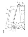
- FIGS. 1 to 3 a first embodiment of the electric bicycle 1 described.
- the electric bicycle 1 comprises a bicycle frame 2, a handlebar 3, a driven rear wheel 4 and a front wheel 5.
- the rear wheel 4 is connected to the bicycle frame 2 via a rear suspension 6.
- the electric bicycle 1 comprises two cranks 7, which are kicked by the driver.
- the pedal cranks 7 are located on a pedal crankshaft 8.
- a carrier 9 is mounted in the bicycle frame 2.
- the carrier 9 has three mounting elements 10.
- a mounting member 10 is mounted on the rear suspension 6.
- Another mounting member 10 is mounted on the bicycle frame under the saddle.
- the third mounting member 10 is mounted on the pedal crankshaft 8.
- an electric motor 11, an accumulator 12 and an electric control 13 are arranged in the carrier 9, an electric motor 11, an accumulator 12 and an electric control 13 (also called circuit) are arranged.
- the electric motor 11 is fed by the accumulator 12 or the electric motor 11 can also be operated as a generator and thus charge the accumulator 12.
- the Control 13 controls the electric motor 11.
- On the handlebar 3 is an operating device 14. About this control device 14, the driver can select different programs or switching stages and thus influence the controller 13.
- first transmission wheel 21 designed as a sprocket cassette.
- second transmission wheel 22 also designed as a sprocket cassette.
- the electric motor 11 directly drives a third transmission wheel 23, designed as a sprocket.
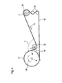
- FIG. 1 shows in a simplified representation of the pedal crankshaft 8 with the first transmission wheel 21 and the rear suspension 6 with the second transmission wheel 22. Furthermore, the driven by the electric motor 11 third transmission wheel 23 is shown.
- a chain tension 24 is provided for tensioning the drive means 12.
- the electric motor 11 provides an engine torque 17, which is introduced at the third transmission wheel 23.
- the motor torque 17 causes at the third transmission wheel the drawn motor drive force 19.
- the motor drive force 19 is at angle ⁇ perpendicular to the pedaling force 18. The same angle ⁇ is at the third transmission wheel 23 also between incoming and outgoing drive means 16 to measure.
- FIG. 3 shows in addition to FIG. 2 nor the carrier 9 with the accumulator 12, the electric motor 11 and the controller 13.
- the controller 13 can be arranged anywhere within the carrier 9.
- FIG. 3 shows FIG. 3 a sensor 26 on the suspension of the electric motor 11.
- the pedaling force 18 and the motor drive force 19 on the third transmission wheel 23 are perpendicular to each other. Therefore, with a very simply designed sensor 26, the pedaling force 18th be measured one-dimensionally. On the basis of the measured pedaling force 18 it is determined how much supporting force the electric motor 11 should perform.
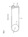
- FIG. 4 shows a second embodiment of the electric bicycle 1.
- the same or functionally identical components are provided in all embodiments with the same reference numerals.
- FIG. 4 only the drive train of the electric bicycle 1 shown.
- the third transmission wheel 23 in particular the axis of the third Transmissionsrades23, below an approximately horizontal imaginary line between the pedal crankshaft 8 and the rear suspension 6.
- the third transmission wheel 23 is between the first and second transmission wheel 21, 22 This arrangement of the electric motor 11 with the third transmission wheel 23 is given a very compact structure of the entire drive train.
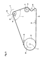
- FIG. 5 shows a third embodiment of the electric bicycle 1.
- the same or functionally identical components are provided in all embodiments with the same reference numerals.
- the third transmission wheel 23, in particular the axis of the third transmission wheel 23, is located above an imaginary line from the pedal crankshaft 8 to the rear suspension 6.
- the third transmission wheel 23 is located behind the first transmission wheel 21 when viewed in the direction of travel Drive means as in conventional bicycles in the first transmission wheel 21 and as a result, a conventional drive means guide 25, in particular chain guide or derailleur can be used.
- the direction of rotation for forward driving is indicated by the reference numeral 16.
- the position of the electric motor 11 with the third transmission wheel 23 in the carrier 9 is preferably adjustable, so that always the angle ⁇ can be adjusted to 90 ° and the chain can be stretched.
Landscapes
- Engineering & Computer Science (AREA)
- Chemical & Material Sciences (AREA)
- Combustion & Propulsion (AREA)
- Transportation (AREA)
- Mechanical Engineering (AREA)
- Electric Propulsion And Braking For Vehicles (AREA)
- Automatic Cycles, And Cycles In General (AREA)
Applications Claiming Priority (1)
| Application Number | Priority Date | Filing Date | Title |
|---|---|---|---|
| DE201210206865 DE102012206865A1 (de) | 2012-04-25 | 2012-04-25 | Elektrofahrrad und Antriebsbausatz für ein Elektrofahrrad |
Publications (1)
| Publication Number | Publication Date |
|---|---|
| EP2657120A1 true EP2657120A1 (fr) | 2013-10-30 |
Family
ID=47757413
Family Applications (1)
| Application Number | Title | Priority Date | Filing Date |
|---|---|---|---|
| EP13156554.1A Withdrawn EP2657120A1 (fr) | 2012-04-25 | 2013-02-25 | Bicyclette électrique et module d'entraînement pour une bicyclette électrique |
Country Status (3)
| Country | Link |
|---|---|
| EP (1) | EP2657120A1 (fr) |
| CN (1) | CN103373432A (fr) |
| DE (1) | DE102012206865A1 (fr) |
Families Citing this family (2)
| Publication number | Priority date | Publication date | Assignee | Title |
|---|---|---|---|---|
| CN104616184A (zh) * | 2015-01-28 | 2015-05-13 | 中国美术学院 | 基于卫星定位系统的公共自行车系统 |
| CN113015670B (zh) * | 2018-05-24 | 2023-05-23 | 博世汽车多媒体葡萄牙公司 | 链驱动式转向角传感器 |
Citations (9)
| Publication number | Priority date | Publication date | Assignee | Title |
|---|---|---|---|---|
| GB1504121A (en) * | 1974-01-31 | 1978-03-15 | Raleigh Industries Ltd | Manually or pedally propelled vehicles such as bicycles |
| JPH09193877A (ja) * | 1996-01-19 | 1997-07-29 | Matsuda Eng:Kk | 電動アシスト多輪自転車 |
| US5758735A (en) * | 1996-07-26 | 1998-06-02 | Aerovironment, Inc. | High performance bicycle propulsion |
| JPH10287288A (ja) * | 1997-04-17 | 1998-10-27 | Akebono Brake Ind Co Ltd | 自転車用補助動力装置 |
| US6591929B1 (en) * | 1999-05-25 | 2003-07-15 | Honda Giken Kogyo Kabushiki Kaisha | Motor-assisted bicycle and power unit |
| WO2009127263A1 (fr) * | 2008-04-18 | 2009-10-22 | Philippe Kohlbrenner | Mécanisme d’entraînement pour véhicule à roues |
| CN201761619U (zh) * | 2010-06-23 | 2011-03-16 | 群真科技股份有限公司 | 电动自行车电力回充装置 |
| US20110284303A1 (en) * | 2008-01-29 | 2011-11-24 | Shaul Shwartz | Portable removable apparatus for powering a bicycle |
| WO2012032731A1 (fr) * | 2010-09-08 | 2012-03-15 | パナソニック株式会社 | Bicyclette électrique |
-
2012
- 2012-04-25 DE DE201210206865 patent/DE102012206865A1/de not_active Withdrawn
-
2013
- 2013-02-25 EP EP13156554.1A patent/EP2657120A1/fr not_active Withdrawn
- 2013-04-22 CN CN 201310139816 patent/CN103373432A/zh active Pending
Patent Citations (9)
| Publication number | Priority date | Publication date | Assignee | Title |
|---|---|---|---|---|
| GB1504121A (en) * | 1974-01-31 | 1978-03-15 | Raleigh Industries Ltd | Manually or pedally propelled vehicles such as bicycles |
| JPH09193877A (ja) * | 1996-01-19 | 1997-07-29 | Matsuda Eng:Kk | 電動アシスト多輪自転車 |
| US5758735A (en) * | 1996-07-26 | 1998-06-02 | Aerovironment, Inc. | High performance bicycle propulsion |
| JPH10287288A (ja) * | 1997-04-17 | 1998-10-27 | Akebono Brake Ind Co Ltd | 自転車用補助動力装置 |
| US6591929B1 (en) * | 1999-05-25 | 2003-07-15 | Honda Giken Kogyo Kabushiki Kaisha | Motor-assisted bicycle and power unit |
| US20110284303A1 (en) * | 2008-01-29 | 2011-11-24 | Shaul Shwartz | Portable removable apparatus for powering a bicycle |
| WO2009127263A1 (fr) * | 2008-04-18 | 2009-10-22 | Philippe Kohlbrenner | Mécanisme d’entraînement pour véhicule à roues |
| CN201761619U (zh) * | 2010-06-23 | 2011-03-16 | 群真科技股份有限公司 | 电动自行车电力回充装置 |
| WO2012032731A1 (fr) * | 2010-09-08 | 2012-03-15 | パナソニック株式会社 | Bicyclette électrique |
Also Published As
| Publication number | Publication date |
|---|---|
| CN103373432A (zh) | 2013-10-30 |
| DE102012206865A1 (de) | 2013-10-31 |
Similar Documents
| Publication | Publication Date | Title |
|---|---|---|
| DE102012016312B4 (de) | Elektrische Servolenkungsvorrichtung | |
| EP2838783B1 (fr) | Antriebseinrichtung für ein elektroraddispositif d'entraînement pour une bicyclette électrique | |
| EP2463189A1 (fr) | Dispositif d'entraînement électromotorisé, notamment pour un deux-roues | |
| EP2216242B1 (fr) | Dispositif d'entraînement | |
| DE112019002605T5 (de) | Motoreinheit und elektrofahrrad | |
| DE69601972T2 (de) | Pedalkraftdetektor für Fahrrad mit Hilfsmotor | |
| EP3020621A1 (fr) | Dispositif de détection destiné à la commande d'un moteur auxiliaire ainsi qu'unité de moyeu de roue dotée d'un tel dispositif de détection | |
| EP3164326A1 (fr) | Unité d'entraînement pour une bicyclette à assistance électrique | |
| DE102017129534A1 (de) | Fahrradantrieb und Fahrradantriebssystem, das einen Fahrradantrieb enthält | |
| DE102011089559A1 (de) | Kurbeltrieb für ein Fahrrad | |
| DE202017107421U1 (de) | Drehmomenterfassungsvorrichtung für ein Fahrrad mit Tretunterstützung | |
| WO2011023366A1 (fr) | Unité d'entraînement | |
| EP2657120A1 (fr) | Bicyclette électrique et module d'entraînement pour une bicyclette électrique | |
| DE102015211157A1 (de) | Verfahren zur Drehmomentbestimmung in einem Riementrieb | |
| DE102020212362A1 (de) | Schaltwerk eines von menschen angetriebenen gefährts | |
| DE112020000938T5 (de) | Motoreinheit und elektrisches Fahrrad | |
| WO1999045351A1 (fr) | Dispositif pour mesurer le travail et la puissance de vehicules a entrainement par chaine | |
| DE102011087784A1 (de) | Kurbeltrieb für ein Fahrrad | |
| EP4467437A1 (fr) | Unité d'entraînement pour un véhicule actionné par force musculaire et/ou motrice, en particulier pour un vélo électrique ou un vélo électrique et procédé de montage d'une unité d'entraînement | |
| EP3439945B1 (fr) | Dispositif d'entraînement muni d'un capteur | |
| DE102022209482B4 (de) | Verfahren zur Steuerung der Antriebsvorrichtung, Steuervorrichtung sowie Fahrrad | |
| DE202014103470U1 (de) | Antriebseinrichtung für ein Elektrorad | |
| WO2021098920A1 (fr) | Dispositif d'entraînement électrique et bicyclette comprenant un dispositif d'entraînement | |
| DE102012210400A1 (de) | Montagemittel für ein Tretunterstützungssystem | |
| DE102013007994B4 (de) | Antriebsvorrichtung für ein Fahrrad mit Elektroantrieb |
Legal Events
| Date | Code | Title | Description |
|---|---|---|---|
| PUAI | Public reference made under article 153(3) epc to a published international application that has entered the european phase |
Free format text: ORIGINAL CODE: 0009012 |
|
| AK | Designated contracting states |
Kind code of ref document: A1 Designated state(s): AL AT BE BG CH CY CZ DE DK EE ES FI FR GB GR HR HU IE IS IT LI LT LU LV MC MK MT NL NO PL PT RO RS SE SI SK SM TR |
|
| AX | Request for extension of the european patent |
Extension state: BA ME |
|
| 17P | Request for examination filed |
Effective date: 20140430 |
|
| RBV | Designated contracting states (corrected) |
Designated state(s): AL AT BE BG CH CY CZ DE DK EE ES FI FR GB GR HR HU IE IS IT LI LT LU LV MC MK MT NL NO PL PT RO RS SE SI SK SM TR |
|
| STAA | Information on the status of an ep patent application or granted ep patent |
Free format text: STATUS: THE APPLICATION IS DEEMED TO BE WITHDRAWN |
|
| 18D | Application deemed to be withdrawn |
Effective date: 20140501 |
|
| R17P | Request for examination filed (corrected) |
Effective date: 20130225 |