EP4467437A1 - Unité d'entraînement pour un véhicule actionné par force musculaire et/ou motrice, en particulier pour un vélo électrique ou un vélo électrique et procédé de montage d'une unité d'entraînement - Google Patents
Unité d'entraînement pour un véhicule actionné par force musculaire et/ou motrice, en particulier pour un vélo électrique ou un vélo électrique et procédé de montage d'une unité d'entraînement Download PDFInfo
- Publication number
- EP4467437A1 EP4467437A1 EP24177947.9A EP24177947A EP4467437A1 EP 4467437 A1 EP4467437 A1 EP 4467437A1 EP 24177947 A EP24177947 A EP 24177947A EP 4467437 A1 EP4467437 A1 EP 4467437A1
- Authority
- EP
- European Patent Office
- Prior art keywords
- drive unit
- housing
- plane
- axis
- motor
- Prior art date
- Legal status (The legal status is an assumption and is not a legal conclusion. Google has not performed a legal analysis and makes no representation as to the accuracy of the status listed.)
- Pending
Links
Images



Classifications
-
- B—PERFORMING OPERATIONS; TRANSPORTING
- B62—LAND VEHICLES FOR TRAVELLING OTHERWISE THAN ON RAILS
- B62M—RIDER PROPULSION OF WHEELED VEHICLES OR SLEDGES; POWERED PROPULSION OF SLEDGES OR SINGLE-TRACK CYCLES; TRANSMISSIONS SPECIALLY ADAPTED FOR SUCH VEHICLES
- B62M6/00—Rider propulsion of wheeled vehicles with additional source of power, e.g. combustion engine or electric motor
- B62M6/40—Rider propelled cycles with auxiliary electric motor
- B62M6/55—Rider propelled cycles with auxiliary electric motor power-driven at crank shafts parts
-
- B—PERFORMING OPERATIONS; TRANSPORTING
- B62—LAND VEHICLES FOR TRAVELLING OTHERWISE THAN ON RAILS
- B62M—RIDER PROPULSION OF WHEELED VEHICLES OR SLEDGES; POWERED PROPULSION OF SLEDGES OR SINGLE-TRACK CYCLES; TRANSMISSIONS SPECIALLY ADAPTED FOR SUCH VEHICLES
- B62M11/00—Transmissions characterised by the use of interengaging toothed wheels or frictionally-engaging wheels
- B62M11/02—Transmissions characterised by the use of interengaging toothed wheels or frictionally-engaging wheels of unchangeable ratio
-
- B—PERFORMING OPERATIONS; TRANSPORTING
- B62—LAND VEHICLES FOR TRAVELLING OTHERWISE THAN ON RAILS
- B62M—RIDER PROPULSION OF WHEELED VEHICLES OR SLEDGES; POWERED PROPULSION OF SLEDGES OR SINGLE-TRACK CYCLES; TRANSMISSIONS SPECIALLY ADAPTED FOR SUCH VEHICLES
- B62M11/00—Transmissions characterised by the use of interengaging toothed wheels or frictionally-engaging wheels
- B62M11/04—Transmissions characterised by the use of interengaging toothed wheels or frictionally-engaging wheels of changeable ratio
- B62M11/06—Transmissions characterised by the use of interengaging toothed wheels or frictionally-engaging wheels of changeable ratio with spur gear wheels
Definitions
- the invention relates to a drive unit for driving a vehicle operated by muscle and/or motor power, as well as a vehicle with a drive unit and a method for assembling a drive unit.
- the vehicle is in particular an eBike, Pedelec or S-Pedelec.
- Drive units for electric bikes are known from e.g. DE102020210864A1
- drive units with pre-assembled components are common practice, but many non-value-adding assembly processes are required, which are caused by complex designs and sometimes multi-part circuit board structures.
- the drive unit according to the invention for a muscle and/or motor-powered vehicle in particular an eBike, Pedelec or S-Pedelec with the features of claim 1, is distinguished from the known device in that all components are arranged in such a way that they can be inserted from one main assembly direction.
- a housing of the drive unit serves to encapsulate the drive unit and forms an envelope against the environment.
- Forces generated by the drive unit can be absorbed in the housing, and external forces can also be transmitted or absorbed by the housing.
- the forces generated inside the drive unit for example caused by the output of a motor, are supported and redirected in the housing.
- the forces acting on the drive unit from outside can be caused by a driver of the vehicle, for example.
- the driver can use a crank drive to propel the vehicle forward.
- the resulting forces, in particular a pedal force are channeled into the interior of the housing and absorbed at suitable bearing points.
- the forces acting on the drive unit from the outside can be caused by an accident or the vehicle hitting a floor.
- the housing protects the components inside it.
- the encapsulation also provides the housing with a protective function against the effects of the weather.
- the housing comprises at least a first and a further housing half.
- the first housing half can be a half-shell, a housing section, a base or the like.
- the first housing half and the at least one Further housing halves can have openings or recesses that can be fully or partially penetrated by the components arranged inside the drive unit.
- the at least one further housing half can be a half-shell, a housing section, a cover or the like.
- the first housing half and the at least one further housing half are detachably or inseparably connected, supported, held or fastened to one another.
- the first housing half and the at least one further housing half can be glued and/or screwed together.
- the stator of the motor is fastened in the first housing half.
- the stator of the motor is part of an electric drive of the drive unit and is fastened detachably or inseparably in the at least first housing half in such a way that it is firmly held in relation to the first housing half.
- the stator is pressed into the at least first housing half, glued, clamped or the like.
- the pedal shaft assembly comprises at least one pedal shaft, which has an interface for cranks of the vehicle and is designed to absorb the pedal force of the driver of the vehicle.
- the pedal force is applied to pedals, which are connected to cranks, which in turn are connected to different ends of a pedal shaft.
- the pedal shaft assembly also comprises means for coupling in an assist torque generated by the motor.
- the at least one first circuit board comprises electronic components for controlling and/or regulating the drive unit.
- the at least one circuit board is to be understood as a main circuit board or central circuit board, which comprises elementary electronic components or components for controlling and/or regulating the drive unit.
- the at least one circuit board can consist of a maximum of one circuit board.
- the at least one first circuit board is not made up of multiple parts.
- the at least one first circuit board can be made and structured from full-surface FR4 plates - for example from epoxy resin and glass fiber fabric - and/or by a circuit board manufacturing process.
- the at least one circuit board can be used to structure the drive unit.
- Structuring can mean, for example, a spatial structure within the drive unit.
- the structuring of the drive unit can mean a functional structure.
- all gear stages of the transmission can be arranged above or below the at least one plate, in one direction, parallel to an axis of the pedal shaft.
- the rotor shaft arrangement comprises a rotor shaft of the motor and at least one further housing component, in particular also elements for supporting the rotor shaft, in particular also a measuring device which comprises a rotor position magnet arrangement.
- the rotor of the motor as a further part of the electric drive, is arranged on the rotor shaft in a rotationally fixed manner.
- the rotor position magnet arrangement in turn comprises in particular a corresponding mounting collar, which can be used to fix the rotor assembly during assembly with respect to a radial direction of the rotor shaft relative to the stator of the motor.
- a rotor position magnet of the rotor position magnet arrangement has, in particular, different magnetic properties along a circumference, so that the angle of rotation of the rotor assembly can be detected with a corresponding sensor.
- the rotor shaft arrangement also comprises in particular a mounting collar.
- the mounting collar is arranged in a housing component of the housing of the drive unit and penetrates it partially or completely. In other words, the housing component surrounds the mounting collar for radial position fixation of the rotor position magnet.
- “Surrounds" can mean a radial enclosing as well as an oval or other type of enclosing.
- the gear which is designed to transmit the assist torque generated by the motor to the pedal shaft assembly, is a spur gear, a bevel gear, a worm gear or the like.
- the gear can be designed in one, two or three stages.
- the gear can have a tray which is designed to accommodate the gear in whole or in part.
- the tray can have recesses.
- the tray can have additional pockets or reservoirs
- the pan can be a carrier for a gear grease or lubrication of the gear.
- assemblies includes the assemblies listed in the features of claim 1, for example the treadle arrangement.
- the assemblies are arranged in such a way that they can be inserted from a main assembly direction.
- the main assembly direction is the assembly direction from which the assembly is fed. In a viewing direction parallel to a treadle, the assemblies can be fed with a feed device in the main assembly direction to their final position in the first housing half.
- the main assembly direction includes
- the assemblies are arranged in such a way that a further translational (x, y) assembly direction and/or rotational assembly direction is provided for the insertion of the assemblies.
- the further translational (x, y) assembly direction and/or rotational assembly direction is a linear movement in an x-direction and/or a y-direction.
- a rotational movement can be a turning and/or pivoting movement.
- the treadmill assembly does not have any interference with the rotor shaft arrangement and the stator of the motor. Interference should be understood as component overlaps or colliding bodies. Conversely, this means, for example, that, from a viewing direction parallel to an axis of the treadmill, the assemblies have a distance, an air gap or the like.
- the assemblies alternatively or additionally have an air gap in an arrangement before insertion, wherein insertion only requires a translational movement and takes place from a direction that is parallel to the viewing direction. For example, an assembly is only guided in the z-direction without an insertion device carrying out a translational x,y movement and/or rotational movement.
- a connector device is arranged in a direction (y) above a first plane.
- the first plane consists of an axis which is coaxial to the Pedal shaft is arranged and another axis that is arranged coaxially to the rotor shaft.
- the plug device can comprise one or more slots for one or more plugs.
- the plug device is an electrical interface of the drive unit to other components of the vehicle.
- the drive unit is connected to a battery module via a cable and is powered by it, whereby a plug coming from the battery module can be plugged into the plug device.
- the connector device is arranged above the first level, following a positive direction (y). It is particularly advantageous that the connector device is arranged in a protected area of a frame component, so that influences such as moisture or dust can be better retained.
- the plug device can also be arranged above a fastening plane.
- the fastening plane is a plane that spans an axis of a first fastening means and an axis of a further fastening means.
- a fastening means is a means with which the drive unit is fastened to a frame component of the vehicle, for example.
- the fastening means comprises recesses, preferably holes in the housing.
- "a first fastening means” and "a further fastening means” mean exactly two fastening means and thus exclude drive units that have more than two fastening means.
- a drive unit can also comprise more than two fastening means.
- a first fastening means and “a further fastening means” mean the fastening means arranged furthest apart from one another.
- a fastening means can also be, for example, a screw, a thread, a through hole, a nut or the like.
- a fastening means can also be a combination of the aforementioned elements.
- the plug device is preferably arranged in a direction (y) below the first plane, the first plane being spanned by an axis which is arranged coaxially to the treadle shaft and a further axis which is arranged coaxially to the rotor shaft.
- the plug device is arranged in a very easily accessible manner and can be quickly plugged in or disconnected for maintenance or repair work.
- "Below the first plane” means that the plug device is arranged below the first plane following a negative direction (y).
- the plug device can also be arranged in particular below the fastening plane.
- the drive unit preferably comprises at least one speed sensor, wherein the at least one speed sensor is arranged on the at least first circuit board and has a first distance from a rear housing surface, wherein the first distance is in a range of 5mm-50mm, preferably 5mm-45mm, particularly preferably -5mm-35mm.
- the speed sensor works in particular with a rim magnet. It is desirable to position the speed sensor close to a rear housing surface so that a signal to be detected from the rim magnet can be detected with sufficient measurement accuracy.
- a first distance to a rear housing surface is in particular the distance of the speed sensor to a rear housing surface when viewed from a direction that is parallel to an axis of the pedal shaft.
- the rear housing surface in particular a part of the rear housing surface, is the surface of the drive unit that runs at an angle to the first plane and is arranged close to the pedal shaft and in a direction relative to the pedal shaft that faces away from the rotor shaft.
- the rear housing surface can also be a plane or surface made up of axes of vertices of housing bulges near the pedal shaft.
- the rear housing surface In a state of a drive unit installed in a vehicle, the rear housing surface is a surface that is arranged on the side of the vehicle facing away from the direction of travel of the vehicle.
- a first distance to a rear housing surface is in particular a minimum distance from the speed sensor to the rear housing surface.
- a first distance to a rear housing surface is in particular a vehicle-dependent distance and can vary depending on an installation position of a drive unit, such that, for example, a minimum distance on a horizontal to the rear housing surface is
- the drive unit preferably comprises at least one speed sensor, wherein the at least one speed sensor is arranged on the at least first circuit board and does not fall below a further distance (u) to a ferromagnetic part, characterized in that the further distance u does not fall below 1 mm - 10 mm, preferably 1 mm - 8 mm, particularly preferably 3 - 7 mm.
- the one further distance (u) to a ferromagnetic part is to be interpreted as a radius.
- the treadle shaft assembly further comprises a measuring device which is suitable for detecting a torque applied to the treadle shaft.
- the measuring device comprises at least one measuring board with a measuring board plane identical to a surface of the measuring board, wherein the measuring board plane is arranged parallel or orthogonal to the first plane.
- the measuring board plane can be arranged at an angle of 20° to 40° to the first plane.
- the measuring device can be, for example, a torque sensor, in particular a magnetoelastic torque sensor, for measuring the pedal torque, which is introduced onto the pedal shaft in particular by a driver of the vehicle.
- orthogonal to the first plane By “parallel to the first plane” is meant “substantially parallel to the first plane”.
- the drive unit comprises fastening means for a chain case, wherein at least two fastening means for the chain case are arranged on a radius, wherein the radius is concentric around the axis of the pedal shaft is arranged and is in particular in a range of 80mm - 110mm, preferably 90mm - 100mm.
- a fastening means for a chain case is a means with which the chain case is supported, held, detachably or permanently attached to the drive unit or the like.
- a fastening means for a chain case comprises in particular recesses, preferably holes, particularly preferably threaded holes, in the housing or a housing half.
- a fastening means for a chain case can also be, for example, a screw, a thread, a through hole, a nut or the like.
- a fastening means for a chain case can also comprise a combination of the aforementioned elements.
- a first housing length is less than 45mm, with an output torque of the drive unit of greater than or equal to 85Nm.
- a first housing length is a distance from the axis of the pedal shaft to a rear housing surface, seen from a direction that is parallel to the axis of the pedal shaft.
- the rear housing surface in particular a part of the rear housing surface, is the surface of the drive unit which runs at an angle to the first plane and is arranged close to the pedal shaft and in a direction relative to the pedal shaft that faces away from the rotor shaft.
- the rear housing surface can also be a plane or surface made up of axes of vertices of housing bulges near the pedal shaft.
- the rear housing surface is a surface that is arranged on the side of the vehicle facing away from the direction of travel of the vehicle.
- An output torque means the assist torque of the motor that is transferred to an output pinion.
- the first housing length is less than 42mm, preferably less than or equal to 40mm, particularly preferably less than or equal to 39mm, with an output torque of the drive unit (2) of greater than or equal to 85Nm.
- the axis of the rotor shaft is arranged below a mounting plane and an axis of the treadle shaft is arranged above the mounting plane, wherein the Fastening plane is spanned by an axis of a first fastening means and an axis of a second fastening means, in particular an exclusively second fastening means.
- Below and above mean a spatial arrangement. The arrangement is seen from a direction that is parallel to the axis of the treadle.
- the invention further relates to a bicycle, in particular an electric bicycle, eBike, Pedelec or S-Pedelec, which comprises a drive unit according to one of the previous embodiments.
- the assembly of a drive unit from previously assembled components is particularly efficient and can be further optimized using the proposed method.
- the components assembled beforehand are prefabricated on different assembly lines and prepared for the proposed method. "Inserting” should therefore also be understood to mean a previous "preparation”, which has not been listed for the sake of clarity. "Preparing a first housing half of a drive unit” is the first step in carrying out the method according to the invention.
- the rotor shaft arrangement is inserted, wherein in particular a shaft journal of the rotor shaft is joined into a bearing arrangement of the housing and at least one further housing component, which aligns the rotor shaft, is joined.
- Inserting the at least one first circuit board includes centering and fastening the at least one first circuit board. Fastening can be done, for example, by screwing, melting plastic pins that penetrate the at least one first circuit board, or by an insulation displacement connection that fastens the circuit board.
- Inserting the gearbox includes in particular aligning a gear arranged on the rotor shaft with a first gear stage of the gearbox.
- the second housing half is put on.
- Putting it on can include applying sealing or adhesive compound and fastening the housing halves.
- the treadle shaft assembly can be used in front of the rotor shaft arrangement or in front of at least the first circuit board. It is particularly advantageous that the assembly of the drive unit can be made more flexible as a result. In one embodiment, in partially or fully automated assembly processes, when a joining system is at a standstill, an assembly process can be brought forward or downstream, which leads to increased availability and faster assembly.
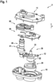
- Figure 1 shows a drive unit 2 according to the invention in an exploded view.
- the housing comprises at least a first housing half 10 and a further housing half 11.
- the first housing half 10 can be a half shell or a base.
- the first housing half 10 and the at least one further housing half 11 have openings which can be partially or completely penetrated by components arranged inside the drive unit 2.
- Figure 1 how a part of the treadle assembly 40 completely penetrates the housing halves 10, 11.
- the at least one further housing half 11 is a half shell or a cover.
- the first housing half 10 and the at least one further housing half 11 are detachably connected and supported on one another.
- the first housing half 10 and the at least one further housing half 11 are screwed together.
- Figure 1 further shows a stator 20 of a motor, which is fastened in the first housing half 10.
- the stator 20 of the motor is part of an electric drive of the drive unit and is fastened detachably or non-detachably in the first housing half 10 in such a way that it cannot move in relation to the first housing half 10.
- the stator 20 is pressed into at least the first housing half 10 (not shown due to the exploded view).
- the pedal shaft assembly 40 comprises an interface for cranks 119 of the vehicle 100 and is designed to absorb a pedal force of the driver of the vehicle 100. Furthermore, Figure 1 a measuring device 41 of the pedal shaft assembly 40, which is configured to determine a driver torque applied to a pedal shaft 103.
- the at least one first circuit board 50 comprises electronic components for controlling and/or regulating the drive unit 2.
- the at least one circuit board 50 is to be understood as a main circuit board or central circuit board, which comprises the elementary electronic components or modules for controlling and/or regulating the drive unit.
- the at least one first board 50 is manufactured and structured by a board manufacturing process.
- the at least one first board 50 can serve to structure the drive unit.
- the structuring brings about a spatial structure within the drive unit. Furthermore, the structuring means a functional structure. As in Figure 1 As can be seen, all gear stages of the gear 60 are arranged above (direction z) of the at least one first circuit board and thus do not require any changes or jumps in the force curves from a circuit board front to a circuit board rear.
- the rotor shaft arrangement 30 also includes elements for supporting the rotor shaft 31, a further housing component 12 and a rotor position magnet arrangement (not shown).
- the rotor 32 of the motor as a further part of the electric drive, is arranged on the rotor shaft 31 in a rotationally fixed manner.
- the gear 60 which is designed to transmit a torque generated by the motor to the pedal shaft assembly 40, is a spur gear.
- the gear can be designed in one, two or three stages.
- Figure 1 indicated that the gear 60 has a tray which is designed to at least partially accommodate the gear 60.
- the tray has recesses.
- the tray has additional pockets or reservoirs (not shown) which serve as a carrier for a gear grease or lubrication of the gear.
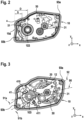
- FIGS. 2 to 5 show schematic internal and external views of a first embodiment of the drive unit in various stages of development. In other words, all views refer to the same first embodiment.
- Figure 2 a schematic interior view of a first embodiment of the drive unit in a first expansion stage.
- a first housing half 10 with a circuit board 50 already inserted and a pedal shaft assembly 40 is shown.
- a speed sensor 51 is shown arranged on the circuit board 50, which is positioned at a first distance S relative to a rear housing surface 10a.
- the distance S is in a range of 26-29 mm.
- a further distance u from the speed sensor 51 to a ferromagnetic part of at least 8 mm is not undercut (not shown).
- Figure 2 further shows a distance D from an axis of the pedal shaft 103 to the rear housing surface 10a. In the first embodiment shown, the distance D is in a range of 35mm to 45mm.
- FIG 3 shows a schematic interior view of a first embodiment of the drive unit 2 in a second expansion stage. Shown is the pedal shaft assembly 40 with a measuring device 41, wherein the measuring device 41 comprises a first measuring board 410 and a second measuring board 411. The first measuring board 410 and the second measuring board are arranged essentially parallel.
- the first measuring board 410 comprises a a surface of the first measuring board 410 identical measuring board level 91a.
- the second measuring board 411 comprises a measuring board level 91b identical to a surface of the second measuring board 411.
- Figure 3 also shows a first plane 90, which is spanned by a first axis, which is arranged coaxially to the pedal shaft 103, and a further axis, which is arranged coaxially to the rotor shaft 31.
- the measuring board planes 91a, 91b are arranged in this specific embodiment at an angle of less than 45° to the first plane 90.
- a fastening plane 92 which is spanned by an axis of a first fastening means 93a and an axis of a second fastening means 93b.
- a fastening means 93a, b is a means with which the drive unit 2 is attached to a frame component 102 (shown in Fig. 9 ) of the vehicle 100.
- Figure 3 It can be seen that the axis of the rotor shaft 31 is located in a negative direction y below the fastening plane 92 and the axis of the treadle shaft is located in a positive direction y, above the fastening plane 92.
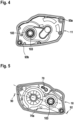
- Figure 4 shows a schematic external view of a first embodiment of the drive unit 2 in a third expansion stage.
- a cover 11 and the pedal shaft 103 are shown, which completely penetrates the cover 11 through a recess in the cover.
- Figure 5 shows a schematic external view of a first housing half 10 of a first embodiment of the drive unit 2 in a third expansion stage.
- Figure 4 and Figure 5 thus show the same expansion stage with a drive unit 2 rotated by 180°.
- a plug device 70 is arranged in a direction y above the first level.
- the plug device 70 can comprise several slots or only one plug.
- the plug device 70 is a Interface of the drive unit 2 to other components of the vehicle 100, such as a display and/or operating unit 122 (see also Fig. 9 ). It is particularly advantageous that the plug device 70 is arranged in a protected area of the frame component 102 so that influences such as moisture or dust can be better retained.
- Figure 5 further shows that the plug device 70 is arranged above the fastening plane 92.
- the plug device 70a (schematically indicated with dashed lines) can also be arranged below the fastening plane 92 or the first plane 90.
- Figure 6 shows a schematic interior view of a second embodiment of the drive unit 2 in a first expansion stage.
- Figure 7 shows a schematic interior view of a third embodiment of the drive unit in a first expansion stage.
- the Figures 6 and 7 are thus at the same stage of development and show in particular the differences in the designs.
- the main focus is on the treadle arrangement 40 with the measuring device 41 present in each case.
- Figures 1 to 5 shown elements of the drive unit 2 are only listed if they are useful for explaining the embodiment.
- Figure 6 shows a measuring device 41 with two measuring boards 410, 411 with the respective measuring board level 91a and the measuring board level 91b.
- the first level 90 is arranged essentially parallel to the measuring board level 91a and the measuring board level 91b.
- Figure 7 shows a measuring device 41 with only one measuring board 410 and the measuring board level 91.
- the first level 90 is essentially orthogonal to the measuring board level 91.
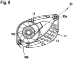
- Figure 7 and Figure 8 show a third embodiment of the drive unit 2.
- Figure 7 shows an interior view of a first stage of construction
- Figure 8 shows an external view of a second expansion stage.
- FIG 8 A cover 11 and the pedal shaft 103 are shown.
- the pedal shaft 103 completely penetrates the cover 11 through a recess.
- three fastening means 14 for a chain case (not shown) are shown, with all three fastening means 14 for the chain case being arranged on a radius 13 of 95mm.
- the radius 13 is arranged concentrically around the axis of the pedal shaft 103.
- the fastening means 14 for the chain case are threaded holes in the embodiment shown.
- FIG 9 shows a simplified schematic view of a bicycle 100, in particular a Pedelec or S-Pedelec, with the drive unit 2.
- the bicycle 100 has a front wheel 115 and a rear wheel 116, wherein the rear wheel 116 is driven on the rear wheel hub 118 by means of a connecting element 101, in particular a toothed belt or a chain, and by means of the drive unit 2 by the pedal force of the cyclist on the pedals 108.
- the pedals 108 are connected to cranks 119, which in turn are connected to different ends of the pedal shaft 103.
- the drive unit 2 is designed to support a driver torque acting on the pedal shaft 103 and to transmit it to an output pinion 107, which is in direct engagement with the connecting element 101 to drive the bicycle 100.
- the frame component 102 of the vehicle 100 comprises in particular a seat tube 106, a down tube 111 with an axis of the down tube 211, a top tube 110, a head tube 112, a chain stay 105, which are inseparably connected to one another, for example welded to one another.
- the bicycle 100 also has a handlebar 120.
- the drive unit 2 is connected to a battery module 109 via a cable (indicated) and is powered by the latter.
- Figure 10 shows a schematic representation of the method 1 according to the invention for assembling a drive unit 2.
- the assembly of a drive unit 2 from previously assembled components is particularly efficient and can be further optimized using the proposed method 1.
- the components assembled beforehand are prefabricated on different assembly lines and prepared for the proposed method 1.
- "inserting” should also be understood to mean a previously performed “preparation”, which is not shown for the sake of clarity.
- the “provision of a first housing half of a drive unit” 150 is the first step in carrying out the method according to the invention.
- a further step 151 the rotor shaft arrangement 30 is inserted, wherein a shaft journal of the rotor shaft 32 is inserted into a bearing arrangement of the housing 10 and at least one further housing component 12, which aligns the rotor shaft 32, is inserted.
- Inserting the at least one first circuit board 50 includes centering and fastening the at least one first circuit board 50 (not shown). Fastening can be carried out, for example, by remelting plastic pins penetrating the at least one first circuit board. Alternatively, an insulation displacement connection, which fastens the circuit board 50, can be used.
- Inserting the gear 60 includes aligning a gear arranged on the rotor shaft 32 with a first gear stage of the gear 60.
- the second housing half is placed on.
- the placement can include applying sealing or adhesive compound and fastening the housing halves.
- the treadle shaft assembly can be assembled in a step 150a before the rotor shaft assembly or in an alternative step 151a before the at least first board 50. It is particularly advantageous that the assembly of the drive unit can be made more flexible. In partially or fully automated assembly processes, for example, if a joining system is at a standstill, an assembly process can be brought forward or downstream, which leads to increased availability and faster assembly.
Landscapes
- Engineering & Computer Science (AREA)
- Chemical & Material Sciences (AREA)
- Combustion & Propulsion (AREA)
- Transportation (AREA)
- Mechanical Engineering (AREA)
- Connection Of Motors, Electrical Generators, Mechanical Devices, And The Like (AREA)
Applications Claiming Priority (1)
| Application Number | Priority Date | Filing Date | Title |
|---|---|---|---|
| DE102023204911.2A DE102023204911A1 (de) | 2023-05-25 | 2023-05-25 | Antriebseinheit für ein mit Muskel- und/oder Motorkraft betriebenes Fahrzeug, insbesondere eBike, Pedelec oder S-Pedelec sowie Verfahren für eine Montage einer Antriebseinheit |
Publications (1)
| Publication Number | Publication Date |
|---|---|
| EP4467437A1 true EP4467437A1 (fr) | 2024-11-27 |
Family
ID=91248807
Family Applications (1)
| Application Number | Title | Priority Date | Filing Date |
|---|---|---|---|
| EP24177947.9A Pending EP4467437A1 (fr) | 2023-05-25 | 2024-05-24 | Unité d'entraînement pour un véhicule actionné par force musculaire et/ou motrice, en particulier pour un vélo électrique ou un vélo électrique et procédé de montage d'une unité d'entraînement |
Country Status (3)
| Country | Link |
|---|---|
| EP (1) | EP4467437A1 (fr) |
| CN (1) | CN222474368U (fr) |
| DE (1) | DE102023204911A1 (fr) |
Cited By (1)
| Publication number | Priority date | Publication date | Assignee | Title |
|---|---|---|---|---|
| US20240239439A1 (en) * | 2021-05-17 | 2024-07-18 | Robert Bosch Gmbh | Drive Assembly |
Citations (4)
| Publication number | Priority date | Publication date | Assignee | Title |
|---|---|---|---|---|
| WO2020100901A1 (fr) * | 2018-11-13 | 2020-05-22 | パナソニックIpマネジメント株式会社 | Unité de transmission de force motrice de bicyclette électrique et bicyclette électrique |
| US20210107593A1 (en) * | 2019-10-11 | 2021-04-15 | Yamaha Hatsudoki Kabushiki Kaisha | Drive unit and electrically assisted bicycle |
| CN112660293A (zh) * | 2021-02-06 | 2021-04-16 | 钟德斌 | 一种牙盘与中轴传感器异轴的高惯量外转子空冷中置电机 |
| DE102020210864A1 (de) | 2020-08-28 | 2022-03-03 | Robert Bosch Gesellschaft mit beschränkter Haftung | Befestigungsanordnung, insbesondere zur Befestigung eines elektrischen Antriebs an einem Elektrofahrrad |
Family Cites Families (8)
| Publication number | Priority date | Publication date | Assignee | Title |
|---|---|---|---|---|
| DE102009014247A1 (de) * | 2009-03-20 | 2010-09-23 | Schaeffler Technologies Gmbh & Co. Kg | Antriebssystem für ein motorisch unterstütztes Fahrrad |
| DE102019205486B4 (de) * | 2019-04-16 | 2020-10-29 | Robert Bosch Gmbh | Antriebseinheit und Arbeitsvorrichtung |
| DE102020203714B4 (de) * | 2020-03-23 | 2021-10-07 | Zf Friedrichshafen Ag | Antriebseinheit und Baugruppe |
| DE102020212908A1 (de) * | 2020-10-13 | 2022-04-14 | KILLWATT GmbH | Gleichzeitig aus menschlicher muskelkraft und elektromotorisch antreibbares fortbewegungsmittel |
| DE102021202572A1 (de) * | 2021-03-16 | 2022-09-22 | Brose Antriebstechnik GmbH & Co. Kommanditgesellschaft, Berlin | Dreistufige Antriebseinheit für ein Elektrofahrrad |
| DE102021110719B3 (de) * | 2021-04-27 | 2022-10-20 | Porsche Ebike Performance Gmbh | Antriebsvorrichtung für ein Elektrofahrrad und Elektrofahrrad |
| DE102021213540A1 (de) * | 2021-11-30 | 2023-06-01 | Robert Bosch Gesellschaft mit beschränkter Haftung | Antriebseinheit eines Elektrofahrrads |
| DE202022104297U1 (de) * | 2022-07-28 | 2022-08-11 | Robert Bosch Gesellschaft mit beschränkter Haftung | Gehäuseanordnung einer Antriebseinheit eines mit Muskelkraft und/oder Motorkraft betreibbaren Fahrzeugs |
-
2023
- 2023-05-25 DE DE102023204911.2A patent/DE102023204911A1/de active Pending
-
2024
- 2024-05-24 EP EP24177947.9A patent/EP4467437A1/fr active Pending
- 2024-05-27 CN CN202421173372.XU patent/CN222474368U/zh active Active
Patent Citations (4)
| Publication number | Priority date | Publication date | Assignee | Title |
|---|---|---|---|---|
| WO2020100901A1 (fr) * | 2018-11-13 | 2020-05-22 | パナソニックIpマネジメント株式会社 | Unité de transmission de force motrice de bicyclette électrique et bicyclette électrique |
| US20210107593A1 (en) * | 2019-10-11 | 2021-04-15 | Yamaha Hatsudoki Kabushiki Kaisha | Drive unit and electrically assisted bicycle |
| DE102020210864A1 (de) | 2020-08-28 | 2022-03-03 | Robert Bosch Gesellschaft mit beschränkter Haftung | Befestigungsanordnung, insbesondere zur Befestigung eines elektrischen Antriebs an einem Elektrofahrrad |
| CN112660293A (zh) * | 2021-02-06 | 2021-04-16 | 钟德斌 | 一种牙盘与中轴传感器异轴的高惯量外转子空冷中置电机 |
Cited By (1)
| Publication number | Priority date | Publication date | Assignee | Title |
|---|---|---|---|---|
| US20240239439A1 (en) * | 2021-05-17 | 2024-07-18 | Robert Bosch Gmbh | Drive Assembly |
Also Published As
| Publication number | Publication date |
|---|---|
| CN222474368U (zh) | 2025-02-14 |
| DE102023204911A1 (de) | 2024-11-28 |
Similar Documents
| Publication | Publication Date | Title |
|---|---|---|
| DE102012016312B4 (de) | Elektrische Servolenkungsvorrichtung | |
| DE102019207817B4 (de) | Antriebseinheit eines menschlich angetriebenen fahrzeugs | |
| DE112019002605T5 (de) | Motoreinheit und elektrofahrrad | |
| DE102022104398A1 (de) | Motoreinheit und elektrofahrrad | |
| DE102011007576A1 (de) | Servolenkungsvorrichtung | |
| EP3325930A1 (fr) | Dispositif de mesure pour mesurer le couple de rotation sur un arbre, mécanisme bielle-manivelle et véhicule | |
| DE102022209899A1 (de) | Antriebsanordnung eines Elektrofahrrads | |
| EP4467437A1 (fr) | Unité d'entraînement pour un véhicule actionné par force musculaire et/ou motrice, en particulier pour un vélo électrique ou un vélo électrique et procédé de montage d'une unité d'entraînement | |
| DE102007019258B4 (de) | Verfahren für den Zusammenbau einer elektrischen Hilfskraftlenkung | |
| DE102023204925A1 (de) | Antriebseinheit eines mit Muskelkraft und/oder Motorkraft betreibbaren Fahrzeugs | |
| EP3766772A1 (fr) | Système de raccordement d'une unité d'entraînement à un cadre de bicyclette | |
| EP2649709B1 (fr) | Actionneur de couple ressenti au volant | |
| DE102022128664B3 (de) | Sensoreinheit und Antriebsvorrichtung für ein Elektrofahrrad und Elektrofahrrad | |
| DE112020000938T5 (de) | Motoreinheit und elektrisches Fahrrad | |
| EP2934987B1 (fr) | Système de capteurs comportant un dispositif capteur de couple et un dispositif capteur d'angle de direction pour un arbre de direction, lequel présente une partie d'arbre d'entrée, côté volant, et une partie d'arbre de sortie, système d'arbre de direction pour un véhicule automobile, véhicule automobile et procédé de fabrication d'un système d'arbre de direction | |
| EP4330121B1 (fr) | Dispositif d'entraînement pour une bicyclette électrique et bicyclette électrique | |
| DE102021110719B3 (de) | Antriebsvorrichtung für ein Elektrofahrrad und Elektrofahrrad | |
| EP4598804A1 (fr) | Unité d'entraînement d'un véhicule pouvant être entraîné par la force musculaire et/ou par la puissance d'un moteur | |
| EP1939067A2 (fr) | Servomoteur électrique d'un système de direction d'un véhicule | |
| DE102022213106A1 (de) | Antriebseinheit für ein mit Muskelkraft und/oder mit Motorkraft betreibbares Fahrzeug | |
| DE102022211932A1 (de) | Antriebsanordnung für ein mit Muskelkraft und/oder mit Motorkraft betreibbares Fahrzeug | |
| EP2657120A1 (fr) | Bicyclette électrique et module d'entraînement pour une bicyclette électrique | |
| DE102009024830B4 (de) | Elektromechanische Lenkung | |
| DE112018007108T5 (de) | Elektronische steuerungsvorrichtung und elektrische antriebsvorrichtung | |
| DE102025124981A1 (de) | Motorpositionserfassungsmagnetaufbau mit integriertem flansch |
Legal Events
| Date | Code | Title | Description |
|---|---|---|---|
| PUAI | Public reference made under article 153(3) epc to a published international application that has entered the european phase |
Free format text: ORIGINAL CODE: 0009012 |
|
| STAA | Information on the status of an ep patent application or granted ep patent |
Free format text: STATUS: THE APPLICATION HAS BEEN PUBLISHED |
|
| AK | Designated contracting states |
Kind code of ref document: A1 Designated state(s): AL AT BE BG CH CY CZ DE DK EE ES FI FR GB GR HR HU IE IS IT LI LT LU LV MC ME MK MT NL NO PL PT RO RS SE SI SK SM TR |
|
| STAA | Information on the status of an ep patent application or granted ep patent |
Free format text: STATUS: REQUEST FOR EXAMINATION WAS MADE |
|
| 17P | Request for examination filed |
Effective date: 20250527 |
|
| STAA | Information on the status of an ep patent application or granted ep patent |
Free format text: STATUS: EXAMINATION IS IN PROGRESS |
|
| 17Q | First examination report despatched |
Effective date: 20260317 |