EP2657626A1 - Dispositif de pompe à chaleur, système de pompe à chaleur, et procédé de commande d'un onduleur triphasé - Google Patents
Dispositif de pompe à chaleur, système de pompe à chaleur, et procédé de commande d'un onduleur triphasé Download PDFInfo
- Publication number
- EP2657626A1 EP2657626A1 EP10861140.1A EP10861140A EP2657626A1 EP 2657626 A1 EP2657626 A1 EP 2657626A1 EP 10861140 A EP10861140 A EP 10861140A EP 2657626 A1 EP2657626 A1 EP 2657626A1
- Authority
- EP
- European Patent Office
- Prior art keywords
- voltage
- value
- phase
- command
- unit
- Prior art date
- Legal status (The legal status is an assumption and is not a legal conclusion. Google has not performed a legal analysis and makes no representation as to the accuracy of the status listed.)
- Granted
Links
Images













Classifications
-
- F—MECHANICAL ENGINEERING; LIGHTING; HEATING; WEAPONS; BLASTING
- F25—REFRIGERATION OR COOLING; COMBINED HEATING AND REFRIGERATION SYSTEMS; HEAT PUMP SYSTEMS; MANUFACTURE OR STORAGE OF ICE; LIQUEFACTION SOLIDIFICATION OF GASES
- F25B—REFRIGERATION MACHINES, PLANTS OR SYSTEMS; COMBINED HEATING AND REFRIGERATION SYSTEMS; HEAT PUMP SYSTEMS
- F25B49/00—Arrangement or mounting of control or safety devices
- F25B49/02—Arrangement or mounting of control or safety devices for compression type machines, plants or systems
- F25B49/025—Motor control arrangements
-
- H—ELECTRICITY
- H02—GENERATION; CONVERSION OR DISTRIBUTION OF ELECTRIC POWER
- H02M—APPARATUS FOR CONVERSION BETWEEN AC AND AC, BETWEEN AC AND DC, OR BETWEEN DC AND DC, AND FOR USE WITH MAINS OR SIMILAR POWER SUPPLY SYSTEMS; CONVERSION OF DC OR AC INPUT POWER INTO SURGE OUTPUT POWER; CONTROL OR REGULATION THEREOF
- H02M7/00—Conversion of AC power input into DC power output; Conversion of DC power input into AC power output
- H02M7/42—Conversion of DC power input into AC power output without possibility of reversal
- H02M7/44—Conversion of DC power input into AC power output without possibility of reversal by static converters
- H02M7/48—Conversion of DC power input into AC power output without possibility of reversal by static converters using discharge tubes with control electrode or semiconductor devices with control electrode
- H02M7/53—Conversion of DC power input into AC power output without possibility of reversal by static converters using discharge tubes with control electrode or semiconductor devices with control electrode using devices of a triode or transistor type requiring continuous application of a control signal
- H02M7/537—Conversion of DC power input into AC power output without possibility of reversal by static converters using discharge tubes with control electrode or semiconductor devices with control electrode using devices of a triode or transistor type requiring continuous application of a control signal using semiconductor devices only, e.g. single switched pulse inverters
- H02M7/5387—Conversion of DC power input into AC power output without possibility of reversal by static converters using discharge tubes with control electrode or semiconductor devices with control electrode using devices of a triode or transistor type requiring continuous application of a control signal using semiconductor devices only, e.g. single switched pulse inverters in a bridge configuration
- H02M7/53871—Conversion of DC power input into AC power output without possibility of reversal by static converters using discharge tubes with control electrode or semiconductor devices with control electrode using devices of a triode or transistor type requiring continuous application of a control signal using semiconductor devices only, e.g. single switched pulse inverters in a bridge configuration with automatic control of output voltage or current
- H02M7/53875—Conversion of DC power input into AC power output without possibility of reversal by static converters using discharge tubes with control electrode or semiconductor devices with control electrode using devices of a triode or transistor type requiring continuous application of a control signal using semiconductor devices only, e.g. single switched pulse inverters in a bridge configuration with automatic control of output voltage or current with analogue control of three-phase output
- H02M7/53876—Conversion of DC power input into AC power output without possibility of reversal by static converters using discharge tubes with control electrode or semiconductor devices with control electrode using devices of a triode or transistor type requiring continuous application of a control signal using semiconductor devices only, e.g. single switched pulse inverters in a bridge configuration with automatic control of output voltage or current with analogue control of three-phase output based on synthesising a desired voltage vector via the selection of appropriate fundamental voltage vectors, and corresponding dwelling times
-
- H—ELECTRICITY
- H02—GENERATION; CONVERSION OR DISTRIBUTION OF ELECTRIC POWER
- H02P—CONTROL OR REGULATION OF ELECTRIC MOTORS, ELECTRIC GENERATORS OR DYNAMO-ELECTRIC CONVERTERS; CONTROLLING TRANSFORMERS, REACTORS OR CHOKE COILS
- H02P29/00—Arrangements for regulating or controlling electric motors, appropriate for both AC and DC motors
- H02P29/60—Controlling or determining the temperature of the motor or of the drive
- H02P29/62—Controlling or determining the temperature of the motor or of the drive for raising the temperature of the motor
-
- F—MECHANICAL ENGINEERING; LIGHTING; HEATING; WEAPONS; BLASTING
- F25—REFRIGERATION OR COOLING; COMBINED HEATING AND REFRIGERATION SYSTEMS; HEAT PUMP SYSTEMS; MANUFACTURE OR STORAGE OF ICE; LIQUEFACTION SOLIDIFICATION OF GASES
- F25B—REFRIGERATION MACHINES, PLANTS OR SYSTEMS; COMBINED HEATING AND REFRIGERATION SYSTEMS; HEAT PUMP SYSTEMS
- F25B2500/00—Problems to be solved
- F25B2500/19—Calculation of parameters
-
- F—MECHANICAL ENGINEERING; LIGHTING; HEATING; WEAPONS; BLASTING
- F25—REFRIGERATION OR COOLING; COMBINED HEATING AND REFRIGERATION SYSTEMS; HEAT PUMP SYSTEMS; MANUFACTURE OR STORAGE OF ICE; LIQUEFACTION SOLIDIFICATION OF GASES
- F25B—REFRIGERATION MACHINES, PLANTS OR SYSTEMS; COMBINED HEATING AND REFRIGERATION SYSTEMS; HEAT PUMP SYSTEMS
- F25B2700/00—Sensing or detecting of parameters; Sensors therefor
- F25B2700/15—Power, e.g. by voltage or current
- F25B2700/151—Power, e.g. by voltage or current of the compressor motor
-
- F—MECHANICAL ENGINEERING; LIGHTING; HEATING; WEAPONS; BLASTING
- F25—REFRIGERATION OR COOLING; COMBINED HEATING AND REFRIGERATION SYSTEMS; HEAT PUMP SYSTEMS; MANUFACTURE OR STORAGE OF ICE; LIQUEFACTION SOLIDIFICATION OF GASES
- F25B—REFRIGERATION MACHINES, PLANTS OR SYSTEMS; COMBINED HEATING AND REFRIGERATION SYSTEMS; HEAT PUMP SYSTEMS
- F25B2700/00—Sensing or detecting of parameters; Sensors therefor
- F25B2700/21—Temperatures
- F25B2700/2106—Temperatures of fresh outdoor air
-
- F—MECHANICAL ENGINEERING; LIGHTING; HEATING; WEAPONS; BLASTING
- F25—REFRIGERATION OR COOLING; COMBINED HEATING AND REFRIGERATION SYSTEMS; HEAT PUMP SYSTEMS; MANUFACTURE OR STORAGE OF ICE; LIQUEFACTION SOLIDIFICATION OF GASES
- F25B—REFRIGERATION MACHINES, PLANTS OR SYSTEMS; COMBINED HEATING AND REFRIGERATION SYSTEMS; HEAT PUMP SYSTEMS
- F25B30/00—Heat pumps
- F25B30/02—Heat pumps of the compression type
-
- H—ELECTRICITY
- H02—GENERATION; CONVERSION OR DISTRIBUTION OF ELECTRIC POWER
- H02M—APPARATUS FOR CONVERSION BETWEEN AC AND AC, BETWEEN AC AND DC, OR BETWEEN DC AND DC, AND FOR USE WITH MAINS OR SIMILAR POWER SUPPLY SYSTEMS; CONVERSION OF DC OR AC INPUT POWER INTO SURGE OUTPUT POWER; CONTROL OR REGULATION THEREOF
- H02M7/00—Conversion of AC power input into DC power output; Conversion of DC power input into AC power output
- H02M7/42—Conversion of DC power input into AC power output without possibility of reversal
- H02M7/44—Conversion of DC power input into AC power output without possibility of reversal by static converters
- H02M7/48—Conversion of DC power input into AC power output without possibility of reversal by static converters using discharge tubes with control electrode or semiconductor devices with control electrode
- H02M7/53—Conversion of DC power input into AC power output without possibility of reversal by static converters using discharge tubes with control electrode or semiconductor devices with control electrode using devices of a triode or transistor type requiring continuous application of a control signal
- H02M7/537—Conversion of DC power input into AC power output without possibility of reversal by static converters using discharge tubes with control electrode or semiconductor devices with control electrode using devices of a triode or transistor type requiring continuous application of a control signal using semiconductor devices only, e.g. single switched pulse inverters
- H02M7/5387—Conversion of DC power input into AC power output without possibility of reversal by static converters using discharge tubes with control electrode or semiconductor devices with control electrode using devices of a triode or transistor type requiring continuous application of a control signal using semiconductor devices only, e.g. single switched pulse inverters in a bridge configuration
- H02M7/53871—Conversion of DC power input into AC power output without possibility of reversal by static converters using discharge tubes with control electrode or semiconductor devices with control electrode using devices of a triode or transistor type requiring continuous application of a control signal using semiconductor devices only, e.g. single switched pulse inverters in a bridge configuration with automatic control of output voltage or current
- H02M7/53873—Conversion of DC power input into AC power output without possibility of reversal by static converters using discharge tubes with control electrode or semiconductor devices with control electrode using devices of a triode or transistor type requiring continuous application of a control signal using semiconductor devices only, e.g. single switched pulse inverters in a bridge configuration with automatic control of output voltage or current with digital control
-
- H—ELECTRICITY
- H02—GENERATION; CONVERSION OR DISTRIBUTION OF ELECTRIC POWER
- H02P—CONTROL OR REGULATION OF ELECTRIC MOTORS, ELECTRIC GENERATORS OR DYNAMO-ELECTRIC CONVERTERS; CONTROLLING TRANSFORMERS, REACTORS OR CHOKE COILS
- H02P27/00—Arrangements or methods for the control of AC motors characterised by the kind of supply voltage
- H02P27/04—Arrangements or methods for the control of AC motors characterised by the kind of supply voltage using variable-frequency supply voltage, e.g. inverter or converter supply voltage
- H02P27/06—Arrangements or methods for the control of AC motors characterised by the kind of supply voltage using variable-frequency supply voltage, e.g. inverter or converter supply voltage using DC to AC converters or inverters
- H02P27/08—Arrangements or methods for the control of AC motors characterised by the kind of supply voltage using variable-frequency supply voltage, e.g. inverter or converter supply voltage using DC to AC converters or inverters with pulse width modulation
- H02P27/085—Arrangements or methods for the control of AC motors characterised by the kind of supply voltage using variable-frequency supply voltage, e.g. inverter or converter supply voltage using DC to AC converters or inverters with pulse width modulation wherein the PWM mode is adapted on the running conditions of the motor, e.g. the switching frequency
Definitions
- the present invention relates to a heating method of a compressor used in a heat pump device.
- Patent Literature 1 there is a description of causing a faint high-frequency open-phase current to flow to a winding of a motor to warm the motor winding when the amount of a liquid refrigerant retained in a compressor reaches a predetermined value or higher. Accordingly, breakage failure of the compressor is prevented by preventing liquid compression due to starting of an operation in a state where a liquid refrigerant is retained in the compressor.
- Patent Literature 2 there is a description of controlling an on/off cycle of a switching element to periodically reverse a direction of a current flowing to a stator coil of a motor.
- this technique not only heat generation due to ohmic loss but also heat generation due to hysteresis loss is performed so that sufficient preheating can be performed with a less consumption current, thereby improving the power efficiency.
- Patent Literature 1 because an open-phase current is caused to flow, there is a winding to which a current does not flow, and thus the compressor can not be uniformly heated. Furthermore, in a case of a permanent magnet synchronous motor having a saliency ratio, a winding inductance depends on a rotor position, and therefore the value of a flowing current changes depending on the rotor position, and thus it is difficult to secure a required heating amount depending on the circumstances.
- any one of the switching elements with one end being connected to a power supply side is repeatedly switched on/off a predetermined number of times during a period of predetermined time. And therewith, after any two of the switching elements with one end being connected to an earth side are switched on for the predetermined period of time, the current flowing to the stator coil is reversed. Therefore, speed-up of a system is required in order to achieve a high frequency operation. Accordingly, the frequency of the current flowing to the winding can not be increased in an inexpensive system, so that there is a limitation in generation of iron loss due to the high frequency configuration, and the efficiency can not be improved. Furthermore, noise is generated.
- the motor winding does not become short-circuited, and the current does not slowly attenuate with a time constant determined by a winding resistance and an inductance. Therefore, the current value of the winding has difficultly in being maintained and a current required for heating may not be secured.
- An object of the present invention is to efficiently heat a refrigerant retained in a compressor.
- the present invention provides a heat pump device comprising:
- the heat pump device generates a drive signal based on a phase ⁇ p and a phase ⁇ n that are switched and outputted in synchronization with a reference signal. Therefore, a high-frequency voltage having a high waveform output accuracy can be generated, and a refrigerant retained in a compressor can be efficiently heated while restraining generation of noise. Furthermore, the heat pump device according to the present invention generates three-phase voltage command values Vu*, Vv* and Vw* in a voltage generation unit, by correcting a voltage command value V* according to a value of a voltage supplied to an inverter to acquire a corrected voltage command value V*'. With this configuration, constant power can be applied to a motor at all times without relying on the value of the voltage applied to the inverter, thereby enabling to prevent breakage of the compressor due to insufficient heating.
- FIG. 1 is a diagram showing a configuration of the heat pump device 100 according to the first embodiment.
- the heat pump device 100 according to the first embodiment includes a refrigeration cycle in which a compressor 1, a four-way valve 2, a heat exchanger 3, an expansion mechanism 4, and a heat exchanger 5 are sequentially connected via a refrigerant pipe 6.
- a compression mechanism 7 that compresses a refrigerant and a motor 8 that actuates the compression mechanism 7 are provided in the compressor 1.
- the motor 8 is a three-phase motor including windings of three phases (U-phase, V-phase, and W-phase).
- An inverter 9 that applies a voltage to the motor 8 to drive it is electrically connected to the motor 8.
- the inverter 9 applies voltages Vu, Vv and Vw to the U-phase, the V-phase and the W-phase windings of the motor 8, respectively.
- the inverter 9 is electrically connected with an inverter control unit 10 including a high-frequency-voltage generation unit 11 and a heating determination unit 12 (state detection unit).
- the inverter control unit 10 determines whether the motor 8 needs to be heated based on a bus voltage Vdc that is a power supply voltage of the inverter 9, transmitted from the inverter 9, and a value of a current I flowing to the motor 8.
- the inverter control unit 10 outputs a PWM (Pulse Width Modulation) signal (drive signal) to the inverter 9.
- PWM Pulse Width Modulation
- FIG. 2 is a diagram showing a configuration of the inverter 9 according to the first embodiment.
- the inverter 9 includes an AC power supply 13, a rectifier 14 that rectifies a voltage supplied from the AC power supply 13, a smoothing capacitor 15 that smoothes the voltage rectified by the rectifier 14 to generate a DC voltage (bus voltage Vdc), and a bus-voltage detection unit 16 that detects the bus voltage Vdc generated by the smoothing capacitor 15 and outputs the bus voltage to the inverter control unit 10.
- the inverter 9 has a voltage application unit 19 using the bus voltage Vdc as a power supply.
- the voltage application unit 19 is a circuit in which three series connection portions of two switching elements (17a and 17d, 17b and 17e, and 17c and 17f) are connected in parallel, and reflux diodes 18a to 18f that are connected in parallel to the respective switching elements 17a to 17f are provided.
- the voltage application unit 19 drives the respective switching elements in accordance with PWM signals UP, VP, WP, UN, VN and WN, respectively, transmitted from the inverter control unit 10 (17a driven by UP, 17b driven by VP, 17c driven by WP, 17d driven by UN, 17e driven by VN, and 17f driven by WN).
- the voltage application unit 19 applies the voltages Vu, Vv and Vw according to the driven switching elements 17 to the U-phase, V-phase and W-phase windings of the motor 8, respectively.
- the inverter 9 includes a current detection unit 20 that detects the current I flowing from the inverter 9 to the motor 8 by applying the voltages Vu, Vv and Vw to the U-phase, V-phase and W-phase windings of the motor 8, respectively, to output the current I to the inverter control unit 10.
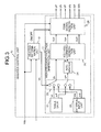
- FIG. 3 is a diagram showing a configuration of the inverter control unit 10 according to the first embodiment.
- the inverter control unit 10 includes the high-frequency-voltage generation unit 11 and the heating determination unit 12.
- the heating determination unit 12 is explained later, and the high-frequency-voltage generation unit 11 is explained here.
- the high-frequency-voltage generation unit 11 includes table data 21, an external input unit 22, a selection unit 23, an integrator 24, a voltage-command generation unit 25, and a PWM-signal generation unit 26.
- the selection unit 23 selects and outputs any one of a voltage command value Vc outputted from the heating determination unit 12, a voltage command value Vt recorded in the table data 21, and a voltage command value Va inputted from the external input unit 22 as a voltage command value V*.
- the selection unit 23 also selects and outputs either a rotation-speed command value ⁇ t recorded in the table data 21 or a rotation-speed command value ⁇ a inputted from the external input unit 22 as a rotation-speed command value ⁇ *.
- the integrator 24 obtains a voltage phase ⁇ based on the rotation-speed command value ⁇ * outputted by the selection unit 23.
- the voltage-command generation unit 25 generates and outputs voltage command values Vu*, Vv* and Vw* using the voltage command value V* outputted by the selection unit 23 and the voltage phase ⁇ obtained by the integrator 24 as inputs thereto.
- the PWM-signal generation unit 26 generates the PWM signals (UP, VP, WP, UN, VN and WN) based on the voltage command values Vu*, Vv* and Vw* outputted by the voltage-command generation unit 25 and the bus voltage Vdc, and outputs the PWM signals to the inverter 9.
- FIG. 4 is a chart showing input/output waveforms of the PWM-signal generation unit 26 according to the first embodiment.
- the voltage command values Vu*, Vv* and Vw* are defined as cosine waves (sine waves) having phases different by 2 ⁇ /3 as shown in Equations (1) to (3).
- V* denotes an amplitude of the voltage command value
- ⁇ denotes a phase of the voltage command value.
- Vw * V * cos ⁇ + 2 / 3 ⁇
- the voltage-command generation unit 25 calculates the voltage command values Vu*, Vv* and Vw* according to Equations (1) to (3) based on the voltage command value V* outputted by the selection unit 23 and the voltage phase ⁇ obtained by the integrator 24, and outputs the calculated voltage command values Vu*, Vv* and Vw* to the PWM-signal generation unit 26.
- the PWM-signal generation unit 26 compares the voltage command values Vu*, Vv* and Vw* with a carrier signal (reference signal) having an amplitude Vdc/2 at a predetermined frequency, and generates PWM signals UP, VP, WP, UN, VN and WN based on a magnitude relation to each other. For example, when the voltage command value Vu* is larger than the carrier signal, UP is set to a voltage for turning on the switching element 17a, and UN is set to a voltage for turning off the switching element 17d.
- FIG. 5 is a chart showing eight switching patterns in the first embodiment.
- reference symbols V0 to V7 denote voltage vectors generated in the respective switching patterns.
- the voltage direction of the respective voltage vectors is indicated by ⁇ U, ⁇ V and ⁇ W (and 0 when the voltage is not generated).
- “+U” means a voltage for generating a current in the U-phase direction, which flows into the motor 8 via the U-phase and flows out from the motor 8 via the V-phase and the W-phase
- “-U” means a voltage for generating a current in the -U phase direction, which flows into the motor 8 via the V-phase and the W-phase and flows out from the motor 8 via the U-phase.
- the inverter 9 can be caused to output desired voltages by combining the switching patterns shown in FIG. 5 and outputting a voltage vector. At this time, a high frequency voltage can be outputted by changing the phase ⁇ at a high speed.
- the voltage command signals Vu*, Vv* and Vw* may be obtained in two-phase modulation, triple harmonic superimposition modulation, space vector modulation, and the like other than Equations (1) to (3).
- FIG. 6 is a diagram showing a configuration of the heating determination unit 12 according to the first embodiment.
- the heating determination unit 12 controls an operation state (ON/OFF) of the high-frequency-voltage generation unit 11 based on the bus voltage Vdc detected by the bus-voltage detection unit 16 of the inverter 9, the current I detected by the current detection unit 20 of the inverter 9, and the like.
- the heating determination unit 12 includes a current comparison unit 27, a voltage comparison unit 28, a temperature detection unit 29, a temperature comparison unit 30, a first logical-product calculation unit 31, a pooling determination unit 32, an elapsed-time measurement unit 33, a time comparison unit 34, a resetting unit 35, a logical-sum calculation unit 36, a second logical-product calculation unit 37, and a heating-amount determination unit 38.
- the current comparison unit 27 output "1" with judging that it is a normal state when the current I detected and outputted by the current detection unit 20 is in a state of Imin ⁇ I ⁇ Imax, but outputs "0" when not in the state.
- the Imax is an upper limit of the current
- the Imin is a lower limit of the current.
- the voltage comparison unit 28 determines that the bus voltage Vdc is in a normal state when the bus voltage Vdc detected by the bus-voltage detection unit 16 is in a state of Vdc_min ⁇ Vdc ⁇ Vdc_max and outputs "1", but outputs "0" in other cases.
- the Vdc_max is an upper limit of the bus voltage
- the Vdc_min is a lower limit of the bus voltage. In the case of an excessive high bus voltage equal to or higher than the Vdc_max or an excessive low bus voltage equal to or lower than the Vdc_min, the voltage comparison unit 28 determines that the bus voltage is in an abnormal state and outputs "0", thereby operating to stop heating.
- the temperature detection unit 29 detects an inverter temperature Tinv that is a temperature of the voltage application unit 19, a temperature Tc of the compressor 1, and an outside air temperature To.
- the temperature comparison unit 30 compares a preset protective temperature Tp_inv of the inverter with the inverter temperature Tinv, and compares a preset protective temperature Tp_c of the compressor 1 with the compressor temperature Tc.
- the temperature comparison unit 30 determines that a normal operation is currently performed in a state of Tp_inv>Tinv and in a state of Tp_c>Tc and outputs "1", but outputs "0" in other cases.
- the inverter temperature is high, and in a case of Tp_c ⁇ Tc, the winding temperature of the motor 8 in the compressor 1 is high, and so an insulation failure or the like may occur. Therefore, the temperature comparison unit 30 determines that it is dangerous, outputs "0", and operates to stop the heating.
- the Tp_c needs to be set, taking into consideration a fact that the compressor 1 has a larger heat capacity than the winding of the motor 8 and the temperature rising speed is lower than that of the winding.
- the first logical-product calculation unit 31 outputs a logical product of output values of the current comparison unit 27, the voltage comparison unit 28 and the temperature comparison unit 30.
- the first logical-product calculation unit 31 outputs "0" to operate to stop the heating.
- a method of stopping heating using the current I, the bus voltage Vdc, and the temperatures Tinv and Tc has been explained. However, not all of these values need to be used. Heating may be stopped using a parameter other than these values.
- the pooling determination unit 32 determines whether or not a liquid refrigerant is retained in the compressor 1 in the compressor 1 (the refrigerant is pooled) based on the temperature Tc of the compressor 1 and the outside air temperature To detected by the temperature detection unit 29. Because the compressor 1 has the largest heat capacity in the refrigeration cycle, and the compressor temperature Tc rises slower compared to the rise of the outdoor air temperature To, the temperature thereof becomes the lowest. Because the refrigerant stays in a place where the temperature is the lowest in the refrigeration cycle, and accumulates as the liquid refrigerant, the refrigerant accumulates in the compressor 1 at the time of temperature rise.
- the pooling determination unit 32 determines that the refrigerant stays in the compressor 1, outputs "1" to start heating, and stops the heating when To ⁇ Tc.
- Control may be executed to start heating when the Tc is in a rising trend or when the To is in a rising trend, and when detection of the Tc or To becomes difficult, the control can be realized using either one of them, thereby enabling to realize highly reliable control.
- the elapsed-time measurement unit 33 measures a time for which the compressor 1 is not heated (Elapse_Time).
- a time limit time Limit_Time preset by the time comparison unit 34 is exceeded, the elapsed-time measurement unit 33 outputs "1" to start heating of the compressor 1.
- the Limit_Time may be set to about 12 hours.
- the Elapse_Time is set to "0" by the resetting unit 35, when the heating of the compressor 1 is executed.
- the logical-sum calculation unit 36 outputs a logical sum of output values of the pooling determination unit 32 and the time comparison unit 34. When at least one of the output values of the pooling determination unit 32 and the time comparison unit 34 becomes “1" indicating starting of the heating, the logical-sum calculation unit 36 outputs "1" to start heating of the compressor "1".
- the second logical-product calculation unit 37 outputs a logical product of the output values of the first logical-product calculation unit 31 and the logical-sum calculation unit 36 as an output value of the heating determination unit 12.
- the output value is 1
- the high-frequency-voltage generation unit 11 is actuated to perform a heating operation of the compressor 1.
- the high-frequency-voltage generation unit 11 is not actuated, and the heating operation of the compressor 1 is not performed, or the operation of the high-frequency-voltage generation unit 11 is stopped to stop the heating operation of the compressor 1.
- the second logical-product calculation unit 37 outputs the logical product, when a signal "0" for stopping heating of the compressor 1 is being outputted by the first logical-product calculation unit 31, the heating can be stopped even if a signal "1" indicating starting of heating is outputted to the logical-sum calculation unit 36. Therefore, it is possible to realize the heat pump device that can minimize power consumption in a standby mode while ensuring certain reliability.
- the pooling determination unit 32 detects a state where a liquid refrigerant is stayed in the compressor 1 based on the compressor temperature Tc and the external temperature To. Furthermore, the heating-amount determination unit 38 determines the amount of the liquid refrigerant retained in the compressor 1 based on the compressor temperature Tc and the external temperature To. The heating-amount determination unit 38 then calculates and outputs the voltage command value Vc required for expelling the refrigerant to outside of the compressor 1 according to the determined amount of the liquid refrigerant. Accordingly, the state where the liquid refrigerant is retained in the compressor 1 can be resolved with the minimum necessary electric power, and the influence on global warming can be reduced with the power consumption being reduced.
- FIG. 7 is a flowchart showing an operation of the inverter control unit 10 in the first embodiment.
- the heating determination unit 12 determines whether to actuate the high-frequency-voltage generation unit 11 by the operation described above during shutdown of the compressor 1.
- the heating determination unit 12 determines that the high-frequency-voltage generation unit 11 should be actuated, that is, when the output value of the heating determination unit 12 is "1" (ON) (YES at S1)
- the process proceeds to S2 to generate PWM signals for preheating.
- the heating determination unit 12 determines that the high-frequency-voltage generation unit 11 should not be actuated, that is, when the output value of the heating determination unit 12 is "0" (OFF) (NO at S1)
- the heating determination unit 12 determines whether to actuate the high-frequency-voltage generation unit 11 again after a predetermined time has passed.
- the selection unit 23 selects the voltage command value V* and the rotation-speed command value ⁇ *, and the integrator 24 obtains the voltage phase ⁇ based on the rotation-speed command value ⁇ * selected by the selection unit 23.
- the voltage-command generation unit 25 calculates the voltage command values Vu*, Vv* and Vw* according to Equations (1) to (3) based on the voltage command value V* selected by the selection unit 23 and the voltage phase ⁇ obtained by the integrator 24, and outputs the calculated voltage command values Vu*, Vv* and Vw* to the PWM-signal generation unit 26.
- the PWM-signal generation unit 26 compares the voltage command values Vu*, Vv* and Vw* outputted by the voltage-command generation unit 25 with the carrier signal to obtain the PWM signals UP, VP, WP, UN, VN and WN, and outputs these PWM signals to the inverter 9. Accordingly, the switching elements 17a to 17f of the inverter 9 are driven to apply a high-frequency voltage to the motor 8.
- the motor 8 is efficiently heated by iron loss of the motor 8 and copper loss generated by the current flowing in the winding.
- the heating determination unit 12 returns to S1 again, and determines whether further heating is required.
- the heat pump device 100 when the liquid refrigerant is stagnating in the compressor 1, the high-frequency voltage is applied to the motor 8, so that the motor 8 can be efficiently heated while restraining noise. Accordingly, the refrigerant retained in the compressor 1 can be efficiently heated, and the retained refrigerant can be leaked to outside of the compressor 1.
- the selection unit 23 had better output a rotation-speed command value ⁇ * equal to or higher than the operation frequency at the time of the compression operation.
- the operation frequency at the time of the compression operation is 1 kHz at most. Therefore, a high frequency voltage having a frequency equal to or larger than 1 kHz only has to be applied to the motor 8.
- the selection unit 23 When a high frequency voltage having a frequency equal to or higher than 14 kHz is applied to the motor 8, vibration sound of an iron core of the motor 8 approaches nearly an upper limit of an audible frequency, so that there is an effect for reducing noise.
- the selection unit 23 outputs the rotation-speed command value ⁇ * for leading to a high frequency voltage of about 20 kHz.
- the frequency of the high frequency voltage exceeds the maximum rated frequency of the switching elements 17a to 17f, a load or power supply short-circuit may occur due to breakage of the switching elements 17a to 17f, and it can lead to generation of smoke or fire. For this reason, it is desired to set the frequency of the high-frequency voltage to be equal to or lower than the maximum rated frequency in order to ensure reliability.
- a motor having an IPM (Interior Permanent Magnet) structure or a concentrated winding motor having a small coil end and a low winding resistance has been widely used for the recent compressor motor for a heat pump device.
- the concentrated winding motor has a small winding resistance and a small amount of heat generation due to copper loss, and thus a large amount of current needs to be caused to flow to the winding. If a large amount of current is caused to flow to the winding, then the current flowing to the inverter 9 also increases, thereby increasing inverter loss. Therefore, if heating by applying the high-frequency voltage described above is performed, then an inductance component by the high frequency increases, thereby increasing winding impedance.
- the mainstream trend is to use silicon (Si) as a material of a semiconductor for the switching elements 17a to 17f that constitute the inverter 9 and the reflux diodes 18a to 18f that are connected to the respective switching elements 17a to 17f in parallel.
- Si silicon
- a wide gap semiconductor whose material is silicon carbide (SiC), gallium nitride (GaN) or diamond may be used. Switching elements and diode elements made from such a wide bandgap semiconductor have a high voltage resistance and a high allowable current density.
- the switching elements and diode elements are possible, and by using these downsized switching elements and diode elements, downsizing of a semiconductor module having these elements incorporated therein can be realized.
- the switching elements and the diode elements made from such a wide bandgap semiconductor have a high heat resistance. Accordingly, downsizing of a radiator fin of a heat sink and air cooling of a water cooling part can be realized, thereby enabling further downsizing of the semiconductor module.
- the switching elements and the diode elements made from such a wide bandgap semiconductor have low power loss. Therefore, the switching elements and the diode elements can be made to have a high efficiency, thereby enabling to make the semiconductor module highly efficient.
- both the switching elements and the diode elements are made from a wide bandgap semiconductor, it is also sufficient that either the switching or diode elements are made from a wide bandgap semiconductor, and even in this case, effects described in the present embodiment can be achieved.
- MOSFET Metal-Oxide-Semiconductor Field-Effect Transistor
- the heating device may be subjected to the restriction of laws and regulations. For this reason, it may as well be admitted that an amplitude of the voltage command value is adjusted so as not to exceed 50W in advance, and/or feedback control is executed with detecting the flowing current and the voltage so as to be 50W or less.
- the inverter control unit 10 is configured by a CPU (Central Processing Unit), a DSP (Digital Signal Processor), a microcomputer, an electronic circuit or the like.
- a CPU Central Processing Unit
- DSP Digital Signal Processor
- microcomputer an electronic circuit or the like.
- a carrier frequency that is a frequency of a carrier signal
- the upper limit of the switching speed is about 20 kHz.
- the carrier frequency is set to 20 kHz in view of the above, if the frequency of the high frequency voltage is set equal to or lower than 2 kHz that is 1/10 of the carrier frequency, then the frequency of the high frequency voltage is in an audible frequency domain, and so it is a concern that noise is increased.
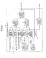
- FIG. 8 is a diagram showing a configuration of the inverter control unit 10 according to the second embodiment.
- the inverter control unit 10 according to the second embodiment is the same as the inverter control unit 10 according to the first embodiment shown in FIG. 3 , except that the high-frequency-voltage generation unit 11 includes an addition unit 39 that adds a phase ⁇ p or a phase ⁇ n switched by the selection unit 23 to the reference phase ⁇ f to obtain the voltage phase ⁇ , instead of the integrator 24 (see FIG. 3 ).
- constituent elements identical to those of the first embodiment are denoted by the same reference signs and explanations thereof will be omitted, and only different points are explained.
- the rotation-speed command value ⁇ * is integrated by the integrator 24 to obtain the voltage phase ⁇ .
- the selection unit 23 (phase switching unit) alternately switches between two types of voltage phases, the phase ⁇ p and the phase ⁇ n that is different from the phase ⁇ p substantially by 180 degrees.
- the addition unit 39 then adds the phase ⁇ p or ⁇ n selected by the selection unit 23 to the reference phase ⁇ f and designates the obtained phase as the voltage phase ⁇ .
- ⁇ p 0 [degree]
- ⁇ n 180 [degrees].
- the selection unit 23 switches between the phases ⁇ p and ⁇ n alternately at the timing of either a top (peak) or bottom (valley) of a carrier signal or at the timings of the top and bottom of the carrier signal.
- the addition unit 39 adds the phase ⁇ p or phase ⁇ n selected by the selection unit 23 to the reference phase ⁇ f, designates the obtained phase as the voltage phase ⁇ , and outputs the voltage phase ⁇ to the voltage-command generation unit 25.
- the voltage-command generation unit 25 obtains the voltage command values Vu*, Vv* and Vw* according to Equations (1) to (3) using the voltage phase ⁇ and the voltage command value V*, and outputs the voltage command values Vu*, Vv* and Vw* to the PWM-signal generation unit 26. Because the selection unit 23 switches between the phases ⁇ p and ⁇ n at the timing of the top or bottom, or at the timings of the top and bottom of the carrier signal, the PWM signal synchronized with the carrier signal can be outputted.
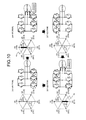
- FIG. 10 is an explanatory diagram of a change of the voltage vector shown in FIG. 9 .
- the switching element 17 surrounded by a broken line is ON, and the switching element 17 not surrounded by a broken line is OFF.
- lines of the motor 8 are short-circuited, and any voltage is not outputted. In this case, the energy accumulated in the inductance of the motor 8 becomes a current, and the current flows in the short circuit.
- a current (current of +Iu current) flows in the direction of the U-phase, in which the current flows into the motor 8 via the U-phase and flows out from the motor 8 via the V-phase and the W-phase
- a current (current of -Iu) flows to the winding of the motor 8 in the direction of the -U phase, in which the current flows into the motor 8 via the V-phase and the W-phase and flows out from the motor 8 via the U-phase. That is, the current flows to the winding of the motor 8 at the time of applying the V4 vector in the opposite direction to that at the time of applying the V3 vector and vice versa.
- the voltage vector changes in order of V0, V4, V7, V3, V0, and so on, the current of +Iu and the current of -Iu flow to the winding of the motor 8 alternately.
- the V4 vector and the V3 vector appear during one carrier cycle (1/fc)
- an AC voltage synchronized with a carrier frequency fc can be applied to the winding of the motor 8.
- the V4 vector (the current of +Iu) and the V3 vector (the current of -Iu) are alternately output, forward and reverse torques are switched instantaneously. Therefore, because the torque is compensated, the voltage application is possible, while suppressing vibrations of the rotor.
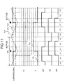
- FIG. 11 is a timing chart when the phase ⁇ p and the phase ⁇ n are alternately switched by the selection unit 23 at a timing of a bottom of a carrier signal.
- the PWM signal changes as shown in FIG. 11 .
- the voltage vector changes to V0, V4, V7, V7, V3, V0, V0, V3, V7, V7, V4, V0, and so on in this order. Because the V4 vector and the V3 vector appear during two carrier cycles, an AC voltage having a frequency half the carrier frequency can be applied to the winding of the motor 8.
- FIG. 12 is an explanatory diagram of a rotor position (a stop position of the rotor) of an IPM motor.
- a rotor position ⁇ of the IPM motor is expressed here by the size of an angle by which the direction of the N pole of the rotor deviates from the U-phase direction.
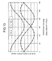
- FIG. 13 is a graph showing current change according to a rotor position.
- the winding inductance depends on the rotor position. Therefore, the winding impedance expressed by a product of an electric angle frequency ⁇ and an inductance value fluctuates according to the rotor position.
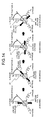
- FIG. 14 is an illustration showing applied voltages when the reference phase ⁇ f is changed with a lapse of time.
- the reference phase ⁇ f is changed every 45 degrees with a lapse of time, at 0 degree, 45 degrees, 90 degrees, 135 degrees, and so on.
- the reference phase ⁇ f is 0 degree
- the phase ⁇ of the voltage command value becomes 0 degree and 180 degrees.
- the reference phase ⁇ f is 45 degrees
- the phase ⁇ of the voltage command value becomes 45 degrees and 225 degrees.
- the reference phase ⁇ f is 90 degrees
- the phase ⁇ of the voltage command value becomes 90 degrees and 270 degrees.
- the phase ⁇ of the voltage command value becomes 135 degrees and 315 degrees. That is, the reference phase ⁇ f is initially set to 0 degree, and the phase ⁇ of the voltage command value is switched between 0 degree and 180 degrees in synchronization with a carrier signal for a predetermined time. Thereafter, the reference phase ⁇ f is switched to 45 degrees, and the phase ⁇ of the voltage command value is switched between 45 degrees and 225 degrees in synchronization with the carrier signal for the predetermined time. Subsequently, the reference phase ⁇ f is switched to 90 degrees and so on.
- phase ⁇ of the voltage command value is switched between 0 degree and 180 degrees, 45 degrees and 225 degrees, 90 degrees and 270 degrees, 135 degrees and 315 degrees, and so on for each predetermined time. Accordingly, because an energization phase of a high-frequency AC voltage changes with a lapse of time, the influence of inductance characteristics according to a rotor stop position can be eliminated, and the compressor 1 can be heated uniformly, regardless of the rotor position.
- FIG. 15 is a chart representing currents flowing to the respective U-, V- and W-phases of the motor 8 when the reference phase ⁇ f is 0 degree (0 degree in the U-phase (V4) direction), 30 degrees, and 60 degrees.
- the reference phase ⁇ f is 0 degree, as shown in FIG. 9 , only one other voltage vector (voltage vector in which, of the switching elements 17a to 17f, one switching element on the positive voltage side and two switching elements on the negative voltage side, or two switching elements on the positive voltage side and one switching element on the negative voltage side become an ON state) is generated between V0 and V7.
- the current waveform becomes a trapezoidal shape and becomes a current having less harmonic components.
- the reference phase ⁇ f when the reference phase ⁇ f is 30 degrees, two different voltage vectors are generated between V0 and V7. In this case, the current waveform is distorted, and the current has plenty of harmonic components. The distortion of the current waveform may cause adverse effects including motor noise, motor shaft vibrations, and the like.
- the reference phase ⁇ f is 60 degrees, only one other voltage vector is generated between V0 and V7, as in the case of the reference phase ⁇ f being 0 degree. In this case, the current waveform becomes a trapezoidal shape and the current has less harmonic components.
- the heat pump device 100 As described above, in the heat pump device 100 according to the second embodiment, two types of phases of a phase ⁇ 1 and a phase ⁇ 2 different from the phase ⁇ 1 substantially by 180 degrees are switched alternately in synchronization with the carrier signal, and used as a phase of the voltage command value. Accordingly, the high frequency voltage synchronized with the carrier frequency can be applied to the winding of the motor 8.
- the reference phase ⁇ f is changed with the lapse of time. Accordingly, because the energization phase of the high-frequency AC voltage changes with the lapse of time, the compressor 1 can be heated uniformly, regardless of the rotor position.
- a third embodiment there is described a method for maintaining a constant heat generation amount of the motor 8 regardless of change in the bus voltage Vdc when the high-frequency AC voltage is generated by the method explained in the second embodiment.
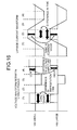
- FIG. 16 is a chart representing a voltage waveform between U and V phases and a U-phase current waveform when there is a difference in the bus voltage Vdc.
- inverter control unit 10 can not set the voltage amplitude high, and therefore the inverter control unit 10 increases a length of an energization time.
- the inverter control unit 10 decreases a length of the energization time, because the voltage amplitude is high. In such a way, the inverter control unit 10 performs control to output the same voltage, regardless of the bus voltage Vdc.
- the inverter control unit 10 operates to cause short-circuit between the lines of the motor 8, and energy accumulated in the inductance of the motor 8 attenuates with a time constant determined by a resistance component and an inductance component of the motor 8. Thereafter, because the voltage between U and V phases becomes negative in a section (3), the U-phase current flows from the positive side to the negative side.
- the inverter control unit 10 operates to cause short-circuit again between the lines of the motor 8, and the energy attenuates with the time constant described above.
- the bus voltage Vdc is large, a length of the time of a zero voltage section of the voltage between U and V phases (section in which the switching pattern becomes the voltage vector V0 or V7 in FIG. 5 ) is elongated. Therefore, the sections (2) and (4) in which the energy attenuates with the time constant determined by the resistance component and the inductance component of the motor 8 become long.
- the previously-mentioned time constant is about several milliseconds, and is sufficiently long with respect to a cycle of 50 microseconds when the output frequency is 20 kilohertz.
- the inverter control unit 10 operates to keep the current generated in the sections (1) and (3). Therefore, as the sections (2) and (4) are longer, that is, as the bus voltage Vdc is larger, a mean value and an effective value of the current become higher.
- the bus voltage Vdc changes according to fluctuations of the voltage of the AC power supply 13. Therefore, the bus voltage Vdc changes and the heat generation amount of the motor 8 changes in an environment in which power supply conditions are poor. When the voltage is low, a required amount of heat generation may be unable to be acquired, and the compressor may be unable to be reliably protected.
- FIG. 17 is a diagram showing a configuration of the inverter control unit 10 according to the third embodiment.
- the inverter control unit 10 according to the third embodiment is the same as the inverter control unit 10 according to the second embodiment shown in FIG. 8 , except that the inverter control unit 10 includes a voltage-command correction-value computation unit 40 that calculates a voltage-command correction value Kv for correcting the voltage command value V*, and that the high-frequency-voltage generation unit 11 includes a multiplier 41 (voltage-command-value calculation unit). Therefore, constituent elements identical to those of the above embodiments are denoted by the same reference signs and explanations thereof will be omitted, and only different points are explained.
- the voltage-command correction-value computation unit 40 and the multiplier 41 are called generally a voltage-command correction unit.
- the voltage-command generation unit 25 uses the voltage command value V* outputted from the selection unit 23 as an input to generate voltage command values Vu*, Vv* and Vw*.
- the multiplier 41 calculates a product of the voltage command value V* outputted by the selection unit 23 (voltage-command-value input unit) and the voltage-command correction value Kv calculated by the voltage-command correction-value computation unit 40 as a voltage command value V*'.
- the voltage-command generation unit 25 uses the voltage command value V*' calculated by the multiplier 41 as an input to generate the voltage command values Vu*, Vv* and Vw*.
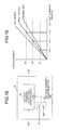
- FIG. 18 is a diagram showing a configuration of the voltage-command correction-value computation unit 40 according to the third embodiment.
- the voltage-command correction-value computation unit 40 includes a voltage-command-value selection unit 42 and a voltage-command correction-value storage unit 43.
- the voltage-command-value selection unit 42 is set to any one of the voltage command value V* outputted by the selection unit 23 and an N/C (No Conection).
- the voltage-command correction-value storage unit 43 stores therein a table of the voltage-command correction value Kv according to the setting of the voltage-command-value selection unit 42.
- FIG. 19 is a figure showing a graph of power of the motor 8 (motor power P) with respect to the voltage command value V* when the bus voltage Vdc takes the smallest, standard and largest values.
- V*1 when the motor 8 is operated at a voltage command value V*1, P1 is acquired when the bus voltage Vdc is standard.
- the voltage command value V* needs to be adjusted in order to apply the same power P1 to the motor 8 regardless of the bus voltage Vdc.
- the voltage-command correction-value storage unit 43 stores therein the corresponding voltage-command correction value Kv for each of the voltage command value V* and the bus voltage Vdc.
- the voltage-command correction value Kv for correcting the voltage command value V* according to the bus voltage Vdc can be acquired for each voltage command value V*, with setting "1" in the case where the bus voltage Vdc is standard.
- the voltage-command correction-value storage unit 43 stores therein a table in which the voltage-command correction value Kv is associated with the bus voltage Vdc, for each voltage command value V*.
- the voltage-command correction-value computation unit 40 then acquires the voltage-command correction value Kv associated with the voltage command value V* and the bus voltage Vdc from the voltage-command correction-value storage unit 43 and outputs the voltage-command correction value Kv.
- the same power can be applied to the motor 8 regardless of the bus voltage Vdc by correcting the voltage command value V* based on the outputted voltage-command correction value Kv. As a result, insufficient heating is prevented and the compressor can be reliably protected.
- the voltage-command-value selection unit 42 is set to N/C.
- N/C a mean value of the voltage-command correction values Kv in the respective voltage command values V* is calculated for each bus voltage Vdc.
- a table in which the mean value is associated with each bus voltage Vdc is created. Accordingly, one table in which the voltage-command correction value Kv is associated with the bus voltage Vdc can be created, regardless of the voltage command value V*.
- the voltage-command correction-value storage unit 43 stores therein one table in which the voltage-command correction value Kv is associated with the bus voltage Vdc. By doing so, even in an inexpensive system with the memory capacity being limited, insufficient heating is prevented, thereby enabling to protect the compressor reliably.
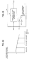
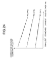
- the voltage-command correction value Kv when the bus voltage Vdc is standard, the voltage-command correction value Kv is set to 1. However, as shown in FIG. 22 , when the bus voltage Vdc takes the smallest value, the voltage-command correction value Kv may be set to 1, or when the bus voltage Vdc takes the largest value, the voltage-command correction value Kv may be set to 1.
- the voltage-command correction-value computation unit 40 may include a corrected voltage-command-value storage unit 44 instead of the voltage-command correction-value storage unit 43.
- the corrected voltage-command-value storage unit 44 stores therein the corrected voltage command value V*' associated with the bus voltage Vdc.
- the voltage-command correction-value computation unit 40 may acquire the voltage command value V*' associated with the voltage command value V* and the bus voltage Vdc from the corrected voltage-command-value storage unit 44 and output the acquired voltage command value V*'.
- the multiplier 41 is not required.
- the table data may be obtained theoretically in other manners than the manner of creating the table data based on actual measurement values.
- the table data relate to a two-dimensional table of the voltage command value V* and the bus voltage Vdc, and so requires a large memory capacity. Therefore, the table data may be replaced by mathematical expressions.
- an interpolation process may be performed using a small amount of table data according to bilinear interpolation or the like, that is a generally known interpolation method.
- the voltage command value V* is corrected according to the bus voltage Vdc, thereby enabling to maintain a constant heat generation amount of the motor 8, regardless of change in the bus voltage Vdc. Accordingly, the heat generation amount of the motor 8 can be maintained constant even in an environment in which power supply conditions are poor, and the required heat generation amount can be acquired even when the voltage is low, thereby enabling to protect the compressor reliably.
- control is made to apply the same power to the motor 8 using the bus voltage Vdc.
- the bus voltage Vdc is produced by rectifying the AC power supply 13 in the rectifier 14, and smoothing the voltage in the smoothing capacitor 15. Therefore, the bus voltage Vdc depends on a value of the AC power supply 13. Accordingly, an AC power-supply voltage Vac, that is a voltage of the AC power supply 13, may be used instead of the bus voltage Vdc to perform the same control as that in the third embodiment.
- an AC power-supply voltage Vac that is a voltage of the AC power supply 13 may be used instead of the bus voltage Vdc to perform the same control as that in the third embodiment.
- a fourth embodiment there is described a method of regularly outputting the motor power P by making the correction using the AC power-supply voltage Vac.
- FIG. 25 is a diagram showing a configuration of the inverter 9 according to the fourth embodiment.
- the inverter 9 according to the fourth embodiment is the same as the inverter 9 according to the first embodiment shown in FIG. 2 , except that the former inverter 9 has an AC-voltage detection unit 45 that detects the AC power-supply voltage Vac. Therefore, constituent elements identical to those of the above embodiments are denoted by the same reference signs and explanations thereof will be omitted, and only different points are explained.
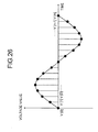
- the AC-voltage detection unit 45 detects a voltage value for at least one phase. Data measured at a certain timing are designated as V[0], V[1], V[2], ... , V[n-1] and V[n] in sequence.
- a mean value of the AC power-supply voltage Vac can be determined by determining a mean value of absolute values of all pieces of detected data. Furthermore, the effective value can be acquired by determining a mean value of a square root of data acquired by squaring and totaling all the pieces of data.
- the AC-voltage detection unit 45 designates the acquired voltage value as the AC power-supply voltage Vac.
- the description is made for a method of determining the AC power-supply voltage Vac by acquiring data discretely in a digital controller such as a microcomputer, but the same calculation may be performed by a continuous system such as an analog circuit.
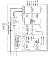
- FIG. 27 is a diagram showing a configuration of the inverter control unit 10 according to the fourth embodiment.
- the inverter control unit 10 according to the fourth embodiment is the same as the inverter control unit 10 according to the third embodiment shown in FIG. 17 , except that the AC power-supply voltage Vac detected by the AC-voltage detection unit 45 is used as an input of the voltage-command correction-value computation unit 40. Therefore, constituent elements identical to those of the above embodiments are denoted by the same reference signs and explanations thereof will be omitted, and only different points are explained.
- FIG. 28 is a diagram showing a configuration of the voltage-command correction-value computation unit 40 according to the fourth embodiment.
- the voltage-command correction-value computation unit 40 according to the fourth embodiment is the same as the voltage-command correction-value computation unit 40 according to the third embodiment shown in FIG. 18 , except that the AC power-supply voltage Vac detected by the AC-voltage detection unit 45 is used as an input. Therefore, constituent elements identical to those of the third embodiment are denoted by the same reference signs and explanations thereof will be omitted, and only different points are explained.
- the voltage-command correction-value storage unit 43 stores therein a table in which the voltage-command correction value Kv is stored corresponding to the AC power-supply voltage Vac.
- control is made using the AC power-supply voltage Vac instead of the bus voltage Vdc. Accordingly, effects identical to those of the third embodiment can be achieved.
- FIG. 1 there is shown the heat pump device 100 in which the compressor 1, the four-way valve 2, the heat exchanger 3, the expansion mechanism 4 and the heat exchanger 5 are sequentially connected by the piping.
- the heat pump device 100 having a more specific configuration is explained.
- FIG. 30 is a circuit configuration diagram of the heat pump device 100 according to the third embodiment.
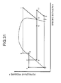
- FIG. 31 is a Mollier diagram of a state of the refrigerant of the heat pump device 100 shown in FIG. 30 .
- a specific enthalpy is indicated on a horizontal axis
- a refrigerant pressure is indicated on a vertical axis.
- a compressor 51, a heat exchanger 52, an expansion mechanism 53, a receiver 54, an internal heat exchanger 55, an expansion mechanism 56, and a heat exchanger 57 are sequentially connected by piping, and the heat pump device 100 includes a main refrigerant circuit 58 through which the refrigerant circulates.
- a four-way valve 59 is provided on a discharge side of the compressor 51, so that a circulation direction of the refrigerant can be switched.
- a fan 60 is provided near the heat exchanger 57.
- the compressor 51 is the compressor 1 explained in the embodiment described above, and includes the motor 8 driven by the inverter 9 and the compression mechanism 7.
- the heat pump device 100 includes an injection circuit 62 that connects from between the receiver 54 and the internal heat exchanger 55 to an injection pipe of the compressor 51 by the piping.
- An expansion mechanism 61 and the internal heat exchanger 55 are sequentially connected to the injection circuit 62.
- a water circuit 63 in which water is circulated is connected to the heat exchanger 52.
- a device that uses water from a hot water dispenser, a radiator, a radiator for floor heating, or the like is connected to the water circuit 63.
- the heating operation includes not only heating used for air conditioning but also hot-water supply for applying heat to water to make hot water.
- the heat exchanger 52 which is a condenser and a radiator
- water circulating in the water circuit 63 is heated by heat radiated from the refrigerant, and used for heating and hot-water supply.
- the liquid-phase refrigerant liquefied by the heat exchanger 52 is pressure-reduced by the expansion mechanism 53, and becomes a gas-liquid two-phase state (at a point 3 in FIG. 31 ).
- the refrigerant which has become the gas-liquid two-phase state in the expansion mechanism 53, is heat exchanged with the refrigerant sucked into the compressor 51 by the receiver 54, and is cooled and liquefied (at a point 4 in FIG. 31 ).
- the liquid-phase refrigerant liquefied by the receiver 54 is branched to the main refrigerant circuit 58 and the injection circuit 62 to flow therein.
- the liquid-phase refrigerant flowing in the main refrigerant circuit 58 is heat exchanged with the refrigerant flowing in the injection circuit 62, which is pressure-reduced by the expansion mechanism 61 and has become the gas-liquid two-phase state, by the internal heat exchanger 55 and is further cooled (at a point 5 in FIG.
- the liquid-phase refrigerant cooled by the internal heat exchanger 55 is pressure-reduced by the expansion mechanism 56 and becomes the gas-liquid two-phase state (at a point 6 in FIG. 31 ).
- the refrigerant, which has become the gas-liquid two-phase state in the expansion mechanism 56, is heat exchanged with ambient air by the heat exchanger 57, which is an evaporator, and is heated (at a point 7 in FIG. 31 ).
- the refrigerant heated by the heat exchanger 57 is further heated by the receiver 54 (at a point 8 in FIG. 31 ), and is sucked into the compressor 51.
- the refrigerant flowing in the injection circuit 62 is pressure-reduced by the expansion mechanism 61 (at a point 9 in FIG. 31 ), and heat exchanged by the internal heat exchanger 55 (at a point 10 in FIG. 31 ).
- a refrigerant (injection refrigerant) in the gas-liquid two-phase state which has been subjected to thermal exchange by the internal heat exchanger 55, flows into inside of the compressor 51 from the injection pipe of the compressor 51 keeping in the gas-liquid two-phase state.
- the refrigerant sucked in from the main refrigerant circuit 58 (at the point 8 in FIG. 31 ) is compressed up to an intermediate pressure and heated (at a point 11 in FIG. 31 ).
- the injection refrigerant joins the refrigerant compressed to the intermediate pressure and heated (at the point 11 in FIG. 31 ), thereby decreasing the temperature (at a point 12 in FIG. 31 ).
- the refrigerant having the decreased temperature is further compressed and heated to have a high temperature and a high pressure, and is discharged (at the point 1 in FIG. 31 ).
- an aperture of the expansion mechanism 61 is fully closed. That is, when the injection operation is performed, the aperture of the expansion mechanism 61 is larger than a predetermined aperture. However, when the injection operation is not performed, the aperture of the expansion mechanism 61 is set to be smaller than the predetermined aperture. Accordingly, the refrigerant does not flow into the injection pipe of the compressor 51.
- the aperture of the expansion mechanism 61 here is controlled by electronic control by a control unit such as a microcomputer.
- the operation of the heat pump device 100 at the time of a cooling operation is explained next.
- the four-way valve 59 is set in a direction of a broken line.
- the cooling operation includes not only cooling used for air conditioning, but also drawing heat from water to make cold water, refrigeration, and the like.
- the gas-phase refrigerant which has become a refrigerant having a high temperature and a high pressure in the compressor 51 (at the point 1 in FIG. 31 ), is discharged from the compressor 51, and is heat exchanged by the heat exchanger 57, which functions as the condenser and the radiator, to be liquefied (at the point 2 in FIG. 31 ).
- the liquid-phase refrigerant liquefied by the heat exchanger 57 is pressure-reduced by the expansion mechanism 56, and becomes a gas-liquid two-phase state (at the point 3 in FIG. 31 ).
- the refrigerant, which has become the gas-liquid two-phase state in the expansion mechanism 56, is heat exchanged by the internal heat exchanger 55, and is cooled and liquefied (at the point 4 in FIG. 31 ).
- the refrigerant, which has become the gas-liquid two-phase state in the expansion mechanism 56 is heat exchanged with the refrigerant (the point 9 in FIG. 31 ), which has become the gas-liquid two-phase state by pressure-reducing the liquid-phase refrigerant liquefied by the internal heat exchanger 55, by the expansion mechanism 56.
- the liquid-phase refrigerant (the point 4 in FIG.
- heat exchanged by the internal heat exchanger 55 is branched to the main refrigerant circuit 58 and the injection circuit 62 to flow therein.
- the liquid-phase refrigerant flowing in the main refrigerant circuit 58 is then heat exchanged with the refrigerant sucked into the compressor 51 by the receiver 54, and is further cooled (at the point 5 in FIG. 31 ).
- the liquid-phase refrigerant cooled by the receiver 54 is pressure-reduced by the expansion mechanism 53 and becomes the gas-liquid two-phase state (at the point 6 in FIG. 31 ).
- the refrigerant which has become the gas-liquid two-phase state in the expansion mechanism 53, is heat exchanged by the heat exchanger 52, which functions as the evaporator, and is heated (at the point 7 in FIG. 31 ). At this time, because the refrigerant absorbs heat, water circulating in the water circuit 63 is cooled and used for cooling and refrigeration. The refrigerant heated by the heat exchanger 52 is further heated by the receiver 54 (at the point 8 in FIG. 31 ), and is sucked into the compressor 51. On the other hand, the refrigerant flowing in the injection circuit 62 is pressure-reduced by the expansion mechanism 61 (at the point 9 in FIG.
- a refrigerant (injection refrigerant) in the gas-liquid two-phase state which has been heat exchanged by the internal heat exchanger 55, flows in from the injection pipe of the compressor 51 keeping in the gas-liquid two-phase state.
- the compression operation in the compressor 51 is the same as that of the heating operation.
- the aperture of the expansion mechanism 61 is fully closed, so as not to result in the refrigerant flowing into the injection pipe of the compressor 51.
- the heat exchanger 52 has been explained as a heat exchanger like a plate type heat exchanger that performs heat exchange between the refrigerant and water circulating in the water circuit 63.
- the heat exchanger 52 is not limited thereto, and may be other types of heat exchangers that perform heat exchange between a refrigerant and air.
- the water circuit 63 may not be a circuit in which water is circulated, but may be a circuit in which another type of fluid is circulated.
- the heat pump device 100 can be used for a heat pump device using an inverter compressor, such as an air conditioner, a heat pump water heater, a refrigerator, a freezer, and the like.
- an inverter compressor such as an air conditioner, a heat pump water heater, a refrigerator, a freezer, and the like.
Landscapes
- Engineering & Computer Science (AREA)
- Power Engineering (AREA)
- Physics & Mathematics (AREA)
- Mechanical Engineering (AREA)
- Thermal Sciences (AREA)
- General Engineering & Computer Science (AREA)
- Inverter Devices (AREA)
- Control Of Ac Motors In General (AREA)
Applications Claiming Priority (1)
| Application Number | Priority Date | Filing Date | Title |
|---|---|---|---|
| PCT/JP2010/073007 WO2012086010A1 (fr) | 2010-12-21 | 2010-12-21 | Dispositif de pompe à chaleur, système de pompe à chaleur, et procédé de commande d'un onduleur triphasé |
Publications (3)
| Publication Number | Publication Date |
|---|---|
| EP2657626A1 true EP2657626A1 (fr) | 2013-10-30 |
| EP2657626A4 EP2657626A4 (fr) | 2016-01-06 |
| EP2657626B1 EP2657626B1 (fr) | 2020-11-25 |
Family
ID=46313314
Family Applications (1)
| Application Number | Title | Priority Date | Filing Date |
|---|---|---|---|
| EP10861140.1A Active EP2657626B1 (fr) | 2010-12-21 | 2010-12-21 | Dispositif de pompe à chaleur, système de pompe à chaleur, et procédé de commande d'un onduleur triphasé |
Country Status (7)
| Country | Link |
|---|---|
| US (1) | US9618249B2 (fr) |
| EP (1) | EP2657626B1 (fr) |
| JP (1) | JP5490260B2 (fr) |
| CN (1) | CN103270376B (fr) |
| AU (1) | AU2010365997B2 (fr) |
| ES (1) | ES2837123T3 (fr) |
| WO (1) | WO2012086010A1 (fr) |
Cited By (1)
| Publication number | Priority date | Publication date | Assignee | Title |
|---|---|---|---|---|
| US10859300B2 (en) | 2016-10-05 | 2020-12-08 | Johnson Controls Technology Company | Variable speed drive for a HVACandR system |
Families Citing this family (26)
| Publication number | Priority date | Publication date | Assignee | Title |
|---|---|---|---|---|
| WO2013046454A1 (fr) | 2011-09-30 | 2013-04-04 | 三菱電機株式会社 | Dispositif de pompe à chaleur, système de pompe à chaleur et procédé de commande d'onduleur |
| JP5937619B2 (ja) * | 2011-12-14 | 2016-06-22 | 三菱電機株式会社 | ヒートポンプ装置ならびに、それを備えた空気調和機、ヒートポンプ給湯機、冷蔵庫、および冷凍機 |
| US10605500B2 (en) | 2012-01-04 | 2020-03-31 | Mitsubishi Electric Corporation | Heat pump device, air conditioner, and freezer |
| WO2013157074A1 (fr) * | 2012-04-16 | 2013-10-24 | 三菱電機株式会社 | Dispositif de pompe à chaleur, appareil de conditionnement d'air et machine de refroidissement |
| CN105209835B (zh) | 2013-05-23 | 2017-05-24 | 三菱电机株式会社 | 热泵装置及具有其的空调机、热泵式热水器、冰箱和制冷机 |
| AT515243A1 (de) * | 2013-12-19 | 2015-07-15 | Schneider Electric Power Drives Gmbh | Verfahren zur Ansteuerung parallel geschalteter Inverter |
| JP5959500B2 (ja) * | 2013-12-27 | 2016-08-02 | 三菱電機株式会社 | 空気調和機及び空気調和機の制御方法 |
| JP6217667B2 (ja) * | 2015-02-19 | 2017-10-25 | 株式会社豊田自動織機 | 電動圧縮機 |
| CN107429931B (zh) * | 2015-04-07 | 2020-03-31 | 日立江森自控空调有限公司 | 空调机 |
| US10277115B2 (en) | 2016-04-15 | 2019-04-30 | Emerson Climate Technologies, Inc. | Filtering systems and methods for voltage control |
| US10312798B2 (en) | 2016-04-15 | 2019-06-04 | Emerson Electric Co. | Power factor correction circuits and methods including partial power factor correction operation for boost and buck power converters |
| US9933842B2 (en) | 2016-04-15 | 2018-04-03 | Emerson Climate Technologies, Inc. | Microcontroller architecture for power factor correction converter |
| US10763740B2 (en) | 2016-04-15 | 2020-09-01 | Emerson Climate Technologies, Inc. | Switch off time control systems and methods |
| US10656026B2 (en) | 2016-04-15 | 2020-05-19 | Emerson Climate Technologies, Inc. | Temperature sensing circuit for transmitting data across isolation barrier |
| US10284132B2 (en) | 2016-04-15 | 2019-05-07 | Emerson Climate Technologies, Inc. | Driver for high-frequency switching voltage converters |
| US10305373B2 (en) | 2016-04-15 | 2019-05-28 | Emerson Climate Technologies, Inc. | Input reference signal generation systems and methods |
| WO2017212584A1 (fr) * | 2016-06-08 | 2017-12-14 | 三菱電機株式会社 | Dispositif d'entraînement de compresseur |
| JP6963495B2 (ja) * | 2017-12-22 | 2021-11-10 | サンデンホールディングス株式会社 | 電力変換装置 |
| US10158299B1 (en) * | 2018-04-18 | 2018-12-18 | Rockwell Automation Technologies, Inc. | Common voltage reduction for active front end drives |
| CN110541810B (zh) * | 2019-09-10 | 2020-09-25 | 青岛海信日立空调系统有限公司 | 一种压缩机驱动电路、控制方法及控制装置、空调 |
| US11211879B2 (en) | 2019-09-23 | 2021-12-28 | Rockwell Automation Technologies, Inc. | Capacitor size reduction and lifetime extension for cascaded H-bridge drives |
| JP7214040B2 (ja) * | 2020-03-27 | 2023-01-27 | 三菱電機株式会社 | 3レベル電力変換装置及び直流電源部の中間電位の制御方法 |
| JP7609054B2 (ja) * | 2021-12-23 | 2025-01-07 | 株式会社豊田自動織機 | 電動圧縮機 |
| CN116667735B (zh) * | 2023-05-22 | 2025-08-26 | 约克广州空调冷冻设备有限公司 | 用于压缩机的预加热装置和预加热方法 |
| WO2025158488A1 (fr) * | 2024-01-22 | 2025-07-31 | 日立ジョンソンコントロールズ空調株式会社 | Dispositif de conversion d'énergie électrique et climatiseur |
| EP4597811A1 (fr) * | 2024-01-31 | 2025-08-06 | Carrier Corporation | Convertisseurs de puissance à topologie réduite pour système de climatisation autoalimenté |
Family Cites Families (45)
| Publication number | Priority date | Publication date | Assignee | Title |
|---|---|---|---|---|
| JPS6068341U (ja) | 1983-10-19 | 1985-05-15 | 株式会社東芝 | ヒ−トポンプ式空気調和機 |
| JPS6191445A (ja) | 1984-10-12 | 1986-05-09 | Matsushita Electric Ind Co Ltd | 空気調和機の圧縮機駆動装置 |
| KR930010466B1 (ko) | 1991-02-26 | 1993-10-25 | 삼성전자 주식회사 | 냉난방겸용 공조기의 콤프레셔 기동 제어방법 |
| JPH08223989A (ja) * | 1995-02-13 | 1996-08-30 | Mitsubishi Electric Corp | 空気調和機の制御装置 |
| JPH08226714A (ja) | 1995-02-23 | 1996-09-03 | Matsushita Electric Ind Co Ltd | 空気調和機 |
| MY119900A (en) | 1995-03-14 | 2005-08-30 | Panasonic Corp | Refrigerating apparatus, and refrigerator control and brushless motor starter used in same |
| JPH11159467A (ja) | 1997-11-28 | 1999-06-15 | Zexel:Kk | 電動機予熱装置における通電制御方法及び電動機予熱装置 |
| JP3616946B2 (ja) | 1998-03-19 | 2005-02-02 | 三菱電機株式会社 | 電動機の駆動装置及びその装置を用いた圧縮機 |
| JPH11324934A (ja) | 1998-05-13 | 1999-11-26 | Matsushita Electric Ind Co Ltd | 空気調和機の圧縮機駆動装置 |
| DE10037972B4 (de) * | 1999-08-05 | 2005-09-15 | Sharp K.K. | Vorrichtung und Verfahren zur Elektromotorsteuerung |
| JP3442024B2 (ja) * | 2000-02-29 | 2003-09-02 | 株式会社日立製作所 | モータ駆動回路及びモータ駆動方法、並びに半導体集積回路装置 |
| US6694287B2 (en) * | 2001-08-30 | 2004-02-17 | Delphi Technologies, Inc. | Phase angle diagnostics for sinusoidal controlled electric machine |
| DE10312234A1 (de) * | 2002-03-20 | 2003-12-18 | Lg Electronics Inc | Betriebssteuervorrichtung und -verfahren für einen Linearkompressor |
| JP3955287B2 (ja) * | 2003-04-03 | 2007-08-08 | 松下電器産業株式会社 | モータ駆動用インバータ制御装置および空気調和機 |
| KR100889823B1 (ko) | 2003-09-04 | 2009-03-20 | 삼성전자주식회사 | 압축기의 제어장치, 공기조화기 및 그 제어방법 |
| KR100566437B1 (ko) | 2003-11-11 | 2006-03-31 | 엘에스산전 주식회사 | 위상천이를 이용한 인버터 고장 검출 장치 및 방법 |
| JP4529540B2 (ja) * | 2004-05-13 | 2010-08-25 | パナソニック株式会社 | 空気調和装置と圧縮機の予熱方法 |
| JP4422567B2 (ja) * | 2004-06-30 | 2010-02-24 | 株式会社日立製作所 | モータ駆動装置,電動アクチュエータおよび電動パワーステアリング装置 |
| ES2249181B1 (es) | 2004-09-14 | 2007-04-16 | Appliances Components Companies Spain, S.A. | Metodo y sistema de control. |
| JP2006118731A (ja) | 2004-10-19 | 2006-05-11 | Matsushita Electric Ind Co Ltd | 空気調和機 |
| US20080041081A1 (en) | 2006-08-15 | 2008-02-21 | Bristol Compressors, Inc. | System and method for compressor capacity modulation in a heat pump |
| JP4757680B2 (ja) | 2006-03-24 | 2011-08-24 | 三菱電機株式会社 | 空気調和装置 |
| JP2007336634A (ja) | 2006-06-13 | 2007-12-27 | Oriental Motor Co Ltd | 多軸駆動システムの洩れ電流抑制装置および方法 |
| JP2008057870A (ja) | 2006-08-31 | 2008-03-13 | Daikin Ind Ltd | 冷凍装置 |
| JP4457124B2 (ja) | 2007-04-06 | 2010-04-28 | 日立アプライアンス株式会社 | コンバータ・インバータ装置 |
| JP5354144B2 (ja) | 2007-10-22 | 2013-11-27 | 東芝キヤリア株式会社 | インバータ |
| JP5468215B2 (ja) | 2008-06-09 | 2014-04-09 | ダイキン工業株式会社 | 空気調和機及び空気調和機の製造方法 |
| JP4471027B2 (ja) | 2008-08-21 | 2010-06-02 | ダイキン工業株式会社 | 直接形変換装置及びその制御方法並びに制御信号生成装置 |
| JP5308109B2 (ja) * | 2008-09-17 | 2013-10-09 | ルネサスエレクトロニクス株式会社 | 同期電動機の駆動システム |
| JP5195444B2 (ja) | 2009-01-14 | 2013-05-08 | パナソニック株式会社 | ブラシレスdcモータの駆動装置並びにこれを用いた冷蔵庫及び空気調和機 |
| JP4985723B2 (ja) | 2009-07-27 | 2012-07-25 | 三菱電機株式会社 | 空気調和機 |
| JP4931970B2 (ja) | 2009-08-10 | 2012-05-16 | 三菱電機株式会社 | 空気調和機 |
| WO2012029099A1 (fr) | 2010-08-30 | 2012-03-08 | 三菱電機株式会社 | Dispositif de pompe à chaleur, système de pompe à chaleur et procédé de commande d'un onduleur triphasé |
| US9543887B2 (en) * | 2010-10-15 | 2017-01-10 | Mitsubishi Electric Corporation | Heat pump device, heat pump system, and method for controlling three-phase inverter |
| WO2012107987A1 (fr) * | 2011-02-07 | 2012-08-16 | 三菱電機株式会社 | Dispositif de pompe à chaleur, système de pompe à chaleur, et procédé de commande pour convertisseur triphasé |
| US9829226B2 (en) * | 2011-04-28 | 2017-11-28 | Mitsubishi Electric Corporation | Heat pump device, heat pump system, and method for controlling inverter |
| WO2013046454A1 (fr) * | 2011-09-30 | 2013-04-04 | 三菱電機株式会社 | Dispositif de pompe à chaleur, système de pompe à chaleur et procédé de commande d'onduleur |
| JP5937619B2 (ja) * | 2011-12-14 | 2016-06-22 | 三菱電機株式会社 | ヒートポンプ装置ならびに、それを備えた空気調和機、ヒートポンプ給湯機、冷蔵庫、および冷凍機 |
| US9231507B2 (en) * | 2012-01-27 | 2016-01-05 | Mitsubishi Electric Corporation | Motor driving curcuit and permanent magnet synchronous motor |
| WO2013132620A1 (fr) * | 2012-03-07 | 2013-09-12 | 三菱電機株式会社 | Climatiseur d'air |
| WO2013157074A1 (fr) * | 2012-04-16 | 2013-10-24 | 三菱電機株式会社 | Dispositif de pompe à chaleur, appareil de conditionnement d'air et machine de refroidissement |
| WO2013190665A1 (fr) * | 2012-06-20 | 2013-12-27 | 三菱電機株式会社 | Dispositif de pompe à chaleur, conditionneur d'air et machine frigorifique |
| US9746216B2 (en) * | 2012-06-29 | 2017-08-29 | Mitsubishi Electric Corporation | Heat pump device, heat pump system, air conditioner, and freezer |
| EP2957919B1 (fr) * | 2013-02-14 | 2017-10-18 | Mitsubishi Electric Corporation | Dispositif de détermination, procédé de détermination, et programme |
| JP6296930B2 (ja) * | 2013-09-17 | 2018-03-20 | 株式会社東芝 | モータ制御装置及び空気調和機 |
-
2010
- 2010-12-21 JP JP2012549511A patent/JP5490260B2/ja active Active
- 2010-12-21 WO PCT/JP2010/073007 patent/WO2012086010A1/fr not_active Ceased
- 2010-12-21 CN CN201080070863.6A patent/CN103270376B/zh active Active
- 2010-12-21 US US13/996,095 patent/US9618249B2/en active Active
- 2010-12-21 EP EP10861140.1A patent/EP2657626B1/fr active Active
- 2010-12-21 AU AU2010365997A patent/AU2010365997B2/en not_active Ceased
- 2010-12-21 ES ES10861140T patent/ES2837123T3/es active Active
Cited By (1)
| Publication number | Priority date | Publication date | Assignee | Title |
|---|---|---|---|---|
| US10859300B2 (en) | 2016-10-05 | 2020-12-08 | Johnson Controls Technology Company | Variable speed drive for a HVACandR system |
Also Published As
| Publication number | Publication date |
|---|---|
| JP5490260B2 (ja) | 2014-05-14 |
| AU2010365997B2 (en) | 2015-03-26 |
| EP2657626A4 (fr) | 2016-01-06 |
| US9618249B2 (en) | 2017-04-11 |
| JPWO2012086010A1 (ja) | 2014-05-22 |
| CN103270376B (zh) | 2015-04-15 |
| WO2012086010A1 (fr) | 2012-06-28 |
| ES2837123T3 (es) | 2021-06-29 |
| US20130291578A1 (en) | 2013-11-07 |
| EP2657626B1 (fr) | 2020-11-25 |
| AU2010365997A1 (en) | 2013-05-09 |
| CN103270376A (zh) | 2013-08-28 |
Similar Documents
| Publication | Publication Date | Title |
|---|---|---|
| EP2657626B1 (fr) | Dispositif de pompe à chaleur, système de pompe à chaleur, et procédé de commande d'un onduleur triphasé | |
| EP2629029B1 (fr) | Dispositif de pompe à chaleur, système de pompe à chaleur, et procédé de commande d'un convertisseur triphasé | |
| EP2763303B1 (fr) | Dispositif de pompe à chaleur, système de pompe à chaleur et procédé de commande d'onduleur | |
| EP2703748B1 (fr) | Dispositif de pompe à chaleur et procédé de commande d'un onduleur dans un dispositif de pompe à chaleur | |
| AU2011358803B2 (en) | Heat pump device, heat pump system, and control method for three-phase inverter | |
| AU2012377681A1 (en) | Heat pump device, air conditioner, and cooling machine | |
| JP6444463B2 (ja) | ヒートポンプ装置 | |
| US10033325B2 (en) | Heat pump device, and air conditioner, heat pump water heater, refrigerator, and freezing machine that includes heat pump device | |
| CN117999445A (zh) | 热泵装置 |
Legal Events
| Date | Code | Title | Description |
|---|---|---|---|
| PUAI | Public reference made under article 153(3) epc to a published international application that has entered the european phase |
Free format text: ORIGINAL CODE: 0009012 |
|
| 17P | Request for examination filed |
Effective date: 20130711 |
|
| AK | Designated contracting states |
Kind code of ref document: A1 Designated state(s): AL AT BE BG CH CY CZ DE DK EE ES FI FR GB GR HR HU IE IS IT LI LT LU LV MC MK MT NL NO PL PT RO RS SE SI SK SM TR |
|
| DAX | Request for extension of the european patent (deleted) | ||
| RA4 | Supplementary search report drawn up and despatched (corrected) |
Effective date: 20151203 |
|
| RIC1 | Information provided on ipc code assigned before grant |
Ipc: H02M 7/48 20070101ALI20151127BHEP Ipc: H02M 7/5387 20070101ALI20151127BHEP Ipc: F25B 49/02 20060101ALI20151127BHEP Ipc: H02P 27/08 20060101ALN20151127BHEP Ipc: F25B 1/00 20060101AFI20151127BHEP Ipc: F25B 30/02 20060101ALI20151127BHEP Ipc: H02M 7/53 20060101ALI20151127BHEP |
|
| STAA | Information on the status of an ep patent application or granted ep patent |
Free format text: STATUS: EXAMINATION IS IN PROGRESS |
|
| 17Q | First examination report despatched |
Effective date: 20190315 |
|
| GRAP | Despatch of communication of intention to grant a patent |
Free format text: ORIGINAL CODE: EPIDOSNIGR1 |
|
| STAA | Information on the status of an ep patent application or granted ep patent |
Free format text: STATUS: GRANT OF PATENT IS INTENDED |
|
| RIC1 | Information provided on ipc code assigned before grant |
Ipc: F25B 30/02 20060101ALI20200602BHEP Ipc: F25B 49/02 20060101ALI20200602BHEP Ipc: F25B 1/00 20060101AFI20200602BHEP Ipc: H02M 7/53 20060101ALI20200602BHEP Ipc: H02P 29/62 20160101ALI20200602BHEP Ipc: H02P 27/08 20060101ALN20200602BHEP Ipc: H02M 7/48 20070101ALI20200602BHEP Ipc: H02M 7/5387 20070101ALI20200602BHEP |
|
| INTG | Intention to grant announced |
Effective date: 20200624 |
|
| GRAS | Grant fee paid |
Free format text: ORIGINAL CODE: EPIDOSNIGR3 |
|
| GRAA | (expected) grant |
Free format text: ORIGINAL CODE: 0009210 |
|
| STAA | Information on the status of an ep patent application or granted ep patent |
Free format text: STATUS: THE PATENT HAS BEEN GRANTED |
|
| AK | Designated contracting states |
Kind code of ref document: B1 Designated state(s): AL AT BE BG CH CY CZ DE DK EE ES FI FR GB GR HR HU IE IS IT LI LT LU LV MC MK MT NL NO PL PT RO RS SE SI SK SM TR |
|
| REG | Reference to a national code |
Ref country code: GB Ref legal event code: FG4D |
|
| REG | Reference to a national code |
Ref country code: CH Ref legal event code: EP |
|
| REG | Reference to a national code |
Ref country code: AT Ref legal event code: REF Ref document number: 1338795 Country of ref document: AT Kind code of ref document: T Effective date: 20201215 |
|
| REG | Reference to a national code |
Ref country code: DE Ref legal event code: R096 Ref document number: 602010066024 Country of ref document: DE |
|
| REG | Reference to a national code |
Ref country code: IE Ref legal event code: FG4D |
|
| REG | Reference to a national code |
Ref country code: SE Ref legal event code: TRGR |
|
| REG | Reference to a national code |
Ref country code: AT Ref legal event code: MK05 Ref document number: 1338795 Country of ref document: AT Kind code of ref document: T Effective date: 20201125 |
|
| REG | Reference to a national code |
Ref country code: NL Ref legal event code: MP Effective date: 20201125 |
|
| PG25 | Lapsed in a contracting state [announced via postgrant information from national office to epo] |
Ref country code: PT Free format text: LAPSE BECAUSE OF FAILURE TO SUBMIT A TRANSLATION OF THE DESCRIPTION OR TO PAY THE FEE WITHIN THE PRESCRIBED TIME-LIMIT Effective date: 20210325 Ref country code: NO Free format text: LAPSE BECAUSE OF FAILURE TO SUBMIT A TRANSLATION OF THE DESCRIPTION OR TO PAY THE FEE WITHIN THE PRESCRIBED TIME-LIMIT Effective date: 20210225 Ref country code: FI Free format text: LAPSE BECAUSE OF FAILURE TO SUBMIT A TRANSLATION OF THE DESCRIPTION OR TO PAY THE FEE WITHIN THE PRESCRIBED TIME-LIMIT Effective date: 20201125 Ref country code: RS Free format text: LAPSE BECAUSE OF FAILURE TO SUBMIT A TRANSLATION OF THE DESCRIPTION OR TO PAY THE FEE WITHIN THE PRESCRIBED TIME-LIMIT Effective date: 20201125 Ref country code: GR Free format text: LAPSE BECAUSE OF FAILURE TO SUBMIT A TRANSLATION OF THE DESCRIPTION OR TO PAY THE FEE WITHIN THE PRESCRIBED TIME-LIMIT Effective date: 20210226 |
|
| PG25 | Lapsed in a contracting state [announced via postgrant information from national office to epo] |
Ref country code: LV Free format text: LAPSE BECAUSE OF FAILURE TO SUBMIT A TRANSLATION OF THE DESCRIPTION OR TO PAY THE FEE WITHIN THE PRESCRIBED TIME-LIMIT Effective date: 20201125 Ref country code: PL Free format text: LAPSE BECAUSE OF FAILURE TO SUBMIT A TRANSLATION OF THE DESCRIPTION OR TO PAY THE FEE WITHIN THE PRESCRIBED TIME-LIMIT Effective date: 20201125 Ref country code: AT Free format text: LAPSE BECAUSE OF FAILURE TO SUBMIT A TRANSLATION OF THE DESCRIPTION OR TO PAY THE FEE WITHIN THE PRESCRIBED TIME-LIMIT Effective date: 20201125 Ref country code: BG Free format text: LAPSE BECAUSE OF FAILURE TO SUBMIT A TRANSLATION OF THE DESCRIPTION OR TO PAY THE FEE WITHIN THE PRESCRIBED TIME-LIMIT Effective date: 20210225 Ref country code: IS Free format text: LAPSE BECAUSE OF FAILURE TO SUBMIT A TRANSLATION OF THE DESCRIPTION OR TO PAY THE FEE WITHIN THE PRESCRIBED TIME-LIMIT Effective date: 20210325 |
|
| REG | Reference to a national code |
Ref country code: LT Ref legal event code: MG9D |
|
| PG25 | Lapsed in a contracting state [announced via postgrant information from national office to epo] |
Ref country code: HR Free format text: LAPSE BECAUSE OF FAILURE TO SUBMIT A TRANSLATION OF THE DESCRIPTION OR TO PAY THE FEE WITHIN THE PRESCRIBED TIME-LIMIT Effective date: 20201125 |
|
| PG25 | Lapsed in a contracting state [announced via postgrant information from national office to epo] |
Ref country code: LT Free format text: LAPSE BECAUSE OF FAILURE TO SUBMIT A TRANSLATION OF THE DESCRIPTION OR TO PAY THE FEE WITHIN THE PRESCRIBED TIME-LIMIT Effective date: 20201125 Ref country code: RO Free format text: LAPSE BECAUSE OF FAILURE TO SUBMIT A TRANSLATION OF THE DESCRIPTION OR TO PAY THE FEE WITHIN THE PRESCRIBED TIME-LIMIT Effective date: 20201125 Ref country code: SM Free format text: LAPSE BECAUSE OF FAILURE TO SUBMIT A TRANSLATION OF THE DESCRIPTION OR TO PAY THE FEE WITHIN THE PRESCRIBED TIME-LIMIT Effective date: 20201125 Ref country code: EE Free format text: LAPSE BECAUSE OF FAILURE TO SUBMIT A TRANSLATION OF THE DESCRIPTION OR TO PAY THE FEE WITHIN THE PRESCRIBED TIME-LIMIT Effective date: 20201125 Ref country code: CZ Free format text: LAPSE BECAUSE OF FAILURE TO SUBMIT A TRANSLATION OF THE DESCRIPTION OR TO PAY THE FEE WITHIN THE PRESCRIBED TIME-LIMIT Effective date: 20201125 Ref country code: SK Free format text: LAPSE BECAUSE OF FAILURE TO SUBMIT A TRANSLATION OF THE DESCRIPTION OR TO PAY THE FEE WITHIN THE PRESCRIBED TIME-LIMIT Effective date: 20201125 |
|
| REG | Reference to a national code |
Ref country code: CH Ref legal event code: PL |
|
| REG | Reference to a national code |
Ref country code: DE Ref legal event code: R097 Ref document number: 602010066024 Country of ref document: DE |
|
| PG25 | Lapsed in a contracting state [announced via postgrant information from national office to epo] |
Ref country code: DK Free format text: LAPSE BECAUSE OF FAILURE TO SUBMIT A TRANSLATION OF THE DESCRIPTION OR TO PAY THE FEE WITHIN THE PRESCRIBED TIME-LIMIT Effective date: 20201125 Ref country code: MC Free format text: LAPSE BECAUSE OF FAILURE TO SUBMIT A TRANSLATION OF THE DESCRIPTION OR TO PAY THE FEE WITHIN THE PRESCRIBED TIME-LIMIT Effective date: 20201125 |
|
| REG | Reference to a national code |
Ref country code: BE Ref legal event code: MM Effective date: 20201231 |
|
| PLBE | No opposition filed within time limit |
Free format text: ORIGINAL CODE: 0009261 |
|
| STAA | Information on the status of an ep patent application or granted ep patent |
Free format text: STATUS: NO OPPOSITION FILED WITHIN TIME LIMIT |
|
| PG25 | Lapsed in a contracting state [announced via postgrant information from national office to epo] |
Ref country code: AL Free format text: LAPSE BECAUSE OF FAILURE TO SUBMIT A TRANSLATION OF THE DESCRIPTION OR TO PAY THE FEE WITHIN THE PRESCRIBED TIME-LIMIT Effective date: 20201125 Ref country code: IE Free format text: LAPSE BECAUSE OF NON-PAYMENT OF DUE FEES Effective date: 20201221 Ref country code: NL Free format text: LAPSE BECAUSE OF FAILURE TO SUBMIT A TRANSLATION OF THE DESCRIPTION OR TO PAY THE FEE WITHIN THE PRESCRIBED TIME-LIMIT Effective date: 20201125 Ref country code: LU Free format text: LAPSE BECAUSE OF NON-PAYMENT OF DUE FEES Effective date: 20201221 |
|
| 26N | No opposition filed |
Effective date: 20210826 |
|
| PG25 | Lapsed in a contracting state [announced via postgrant information from national office to epo] |
Ref country code: SI Free format text: LAPSE BECAUSE OF FAILURE TO SUBMIT A TRANSLATION OF THE DESCRIPTION OR TO PAY THE FEE WITHIN THE PRESCRIBED TIME-LIMIT Effective date: 20201125 Ref country code: LI Free format text: LAPSE BECAUSE OF NON-PAYMENT OF DUE FEES Effective date: 20201231 Ref country code: CH Free format text: LAPSE BECAUSE OF NON-PAYMENT OF DUE FEES Effective date: 20201231 |
|
| PG25 | Lapsed in a contracting state [announced via postgrant information from national office to epo] |
Ref country code: IS Free format text: LAPSE BECAUSE OF FAILURE TO SUBMIT A TRANSLATION OF THE DESCRIPTION OR TO PAY THE FEE WITHIN THE PRESCRIBED TIME-LIMIT Effective date: 20210325 Ref country code: TR Free format text: LAPSE BECAUSE OF FAILURE TO SUBMIT A TRANSLATION OF THE DESCRIPTION OR TO PAY THE FEE WITHIN THE PRESCRIBED TIME-LIMIT Effective date: 20201125 Ref country code: MT Free format text: LAPSE BECAUSE OF FAILURE TO SUBMIT A TRANSLATION OF THE DESCRIPTION OR TO PAY THE FEE WITHIN THE PRESCRIBED TIME-LIMIT Effective date: 20201125 Ref country code: CY Free format text: LAPSE BECAUSE OF FAILURE TO SUBMIT A TRANSLATION OF THE DESCRIPTION OR TO PAY THE FEE WITHIN THE PRESCRIBED TIME-LIMIT Effective date: 20201125 |
|
| PG25 | Lapsed in a contracting state [announced via postgrant information from national office to epo] |
Ref country code: MK Free format text: LAPSE BECAUSE OF FAILURE TO SUBMIT A TRANSLATION OF THE DESCRIPTION OR TO PAY THE FEE WITHIN THE PRESCRIBED TIME-LIMIT Effective date: 20201125 |
|
| PG25 | Lapsed in a contracting state [announced via postgrant information from national office to epo] |
Ref country code: BE Free format text: LAPSE BECAUSE OF NON-PAYMENT OF DUE FEES Effective date: 20201231 |
|
| P01 | Opt-out of the competence of the unified patent court (upc) registered |
Effective date: 20230512 |
|
| PGFP | Annual fee paid to national office [announced via postgrant information from national office to epo] |
Ref country code: SE Payment date: 20231110 Year of fee payment: 14 Ref country code: IT Payment date: 20231110 Year of fee payment: 14 Ref country code: FR Payment date: 20231108 Year of fee payment: 14 |
|
| PGFP | Annual fee paid to national office [announced via postgrant information from national office to epo] |
Ref country code: ES Payment date: 20240110 Year of fee payment: 14 |
|
| REG | Reference to a national code |
Ref country code: SE Ref legal event code: EUG |
|
| PG25 | Lapsed in a contracting state [announced via postgrant information from national office to epo] |
Ref country code: IT Free format text: LAPSE BECAUSE OF NON-PAYMENT OF DUE FEES Effective date: 20241221 |
|
| PG25 | Lapsed in a contracting state [announced via postgrant information from national office to epo] |
Ref country code: FR Free format text: LAPSE BECAUSE OF NON-PAYMENT OF DUE FEES Effective date: 20241231 |
|
| PGFP | Annual fee paid to national office [announced via postgrant information from national office to epo] |
Ref country code: DE Payment date: 20251028 Year of fee payment: 16 |
|
| PGFP | Annual fee paid to national office [announced via postgrant information from national office to epo] |
Ref country code: GB Payment date: 20251030 Year of fee payment: 16 |
|
| REG | Reference to a national code |
Ref country code: ES Ref legal event code: FD2A Effective date: 20260203 |
|
| PG25 | Lapsed in a contracting state [announced via postgrant information from national office to epo] |
Ref country code: ES Free format text: LAPSE BECAUSE OF NON-PAYMENT OF DUE FEES Effective date: 20241222 |