EP2657737A1 - Heizvorrichtung zur glasfaserverstärkung und glasfaser-fusionsspleissvorrichtung - Google Patents
Heizvorrichtung zur glasfaserverstärkung und glasfaser-fusionsspleissvorrichtung Download PDFInfo
- Publication number
- EP2657737A1 EP2657737A1 EP11851583.2A EP11851583A EP2657737A1 EP 2657737 A1 EP2657737 A1 EP 2657737A1 EP 11851583 A EP11851583 A EP 11851583A EP 2657737 A1 EP2657737 A1 EP 2657737A1
- Authority
- EP
- European Patent Office
- Prior art keywords
- optical fiber
- heating device
- protector
- sleeve
- accommodation groove
- Prior art date
- Legal status (The legal status is an assumption and is not a legal conclusion. Google has not performed a legal analysis and makes no representation as to the accuracy of the status listed.)
- Granted
Links
Images


Classifications
-
- G—PHYSICS
- G02—OPTICS
- G02B—OPTICAL ELEMENTS, SYSTEMS OR APPARATUS
- G02B6/00—Light guides; Structural details of arrangements comprising light guides and other optical elements, e.g. couplings
- G02B6/24—Coupling light guides
- G02B6/255—Splicing of light guides, e.g. by fusion or bonding
-
- G—PHYSICS
- G02—OPTICS
- G02B—OPTICAL ELEMENTS, SYSTEMS OR APPARATUS
- G02B6/00—Light guides; Structural details of arrangements comprising light guides and other optical elements, e.g. couplings
- G02B6/24—Coupling light guides
- G02B6/36—Mechanical coupling means
-
- G—PHYSICS
- G02—OPTICS
- G02B—OPTICAL ELEMENTS, SYSTEMS OR APPARATUS
- G02B6/00—Light guides; Structural details of arrangements comprising light guides and other optical elements, e.g. couplings
- G02B6/24—Coupling light guides
- G02B6/255—Splicing of light guides, e.g. by fusion or bonding
- G02B6/2553—Splicing machines, e.g. optical fibre fusion splicer
-
- G—PHYSICS
- G02—OPTICS
- G02B—OPTICAL ELEMENTS, SYSTEMS OR APPARATUS
- G02B6/00—Light guides; Structural details of arrangements comprising light guides and other optical elements, e.g. couplings
- G02B6/24—Coupling light guides
- G02B6/255—Splicing of light guides, e.g. by fusion or bonding
- G02B6/2558—Reinforcement of splice joint
-
- G—PHYSICS
- G02—OPTICS
- G02B—OPTICAL ELEMENTS, SYSTEMS OR APPARATUS
- G02B6/00—Light guides; Structural details of arrangements comprising light guides and other optical elements, e.g. couplings
- G02B6/24—Coupling light guides
- G02B6/36—Mechanical coupling means
- G02B6/38—Mechanical coupling means having fibre to fibre mating means
- G02B6/3801—Permanent connections, i.e. wherein fibres are kept aligned by mechanical means
- G02B6/3802—Assembly tools, e.g. crimping tool or pressing bench
Definitions
- the present invention relates to an optical fiber reinforcing heating device for heating and shrinking a fiber reinforcement sleeve covering a fusion-splicing part of optical fibers and an optical fiber fusion-splicing device equipped with the optical fiber reinforcing heating device.
- an optical fiber reinforcing heating device for an optical fiber fusion-splicing device one comprising a heating table having an accommodation unit that contains a fiber reinforcement sleeve covering a fusion-splicing part of optical fibers, which heats the fiber reinforcement sleeve; a pair of coated fiber pressing parts disposed at both ends of the heating table and grasping the optical fibers; and a lid part that covers the accommodation unit has been known, as disclosed in Patent Literature 1, for example.
- the present invention relates to an optical fiber reinforcing heating device for heating and shrinking a fiber reinforcement sleeve covering a fusion-splicing part of optical fibers.
- the optical fiber reinforcing heating device comprises a base part having a sleeve accommodation groove that contains the fiber reinforcement sleeve; a heater that heats the fiber reinforcement sleeve contained in the sleeve accommodation groove; a pair of fiber clamping parts that clamps the optical fibers, which is arranged on both end sides of the sleeve accommodation groove; a lid part attached openably and closably to the base part, the lid part covering the sleeve accommodation groove; and a protector, joined to the lid part, which prevents winds from entering the sleeve accommodation groove in a state where the lid part is closed.
- the lid part When heating and shrinking a fiber reinforcement sleeve covering a fusion-splicing part of optical fibers by using thus constructed optical fiber reinforcing heating device, the lid part is closed while the fiber reinforcement sleeve is contained in the sleeve accommodation groove of the base part, so as to cover the sleeve accommodation groove, an optical fiber is clamped to each fiber clamping part, and then the fiber reinforcement sleeve is heated by the heater.
- the protector joined to the lid part inhibits the wind from entering the sleeve accommodation groove. Therefore, the optical fiber reinforcing heating device in accordance with the present invention prevents winds from dissipating heat from the heater and thus can appropriately heat and shrink the fiber reinforcement sleeve.
- the protector may be joined to the lid part such as to descend along a side face of the base part when the lid part is opened.
- the protector does not project sideways from the base part in a state where the lid part is open, whereby no large operation space is necessary.
- the base part may have a guide part that guides the protector such that the protector descends along the side face of the base part when the lid part is opened, the guide part including a depression adapted to engage the protector.
- the heater may have a U-shaped cross section and be arranged such as to extend along bottom and side faces of the sleeve accommodation groove. Using the heater having such a U-shaped cross section can efficiently heat the fiber reinforcement sleeve as a whole.
- the protector may have an L-shaped cross section. In this case, even when the heat of the heater is transmitted to a side wall of the base part, so as to make it hotter, the protector having the L-shaped cross section secures a sufficient airspace between the side wall and the protector without being separated from the side wall and thus can make it harder for the heat to transmit from the side wall to the protector. This allows the protector to protect operators against the heat of the side wall without increasing the size of the optical fiber reinforcing heating device.
- the optical fiber fusion-splicing device of the present invention comprises a fusion splicer that fusion-splices an optical fiber and any of the optical fiber reinforcing heating devices mentioned above.
- optical fiber fusion-splicing device prevents winds from dissipating heat from the heater as mentioned above and thus can appropriately heat and shrink the fiber reinforcement sleeve.
- the present invention can mitigate influences of winds on heating and shrinking the fiber reinforcement sleeve. This makes it possible to shrink the fiber reinforcement sleeve without taking a long time.
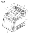
- Fig. 1 is a perspective view illustrating the exterior of one embodiment of the optical fiber fusion-splicing device in accordance with the present invention.
- the optical fiber fusion-splicing device 1 of this embodiment is equipped with a box-shaped housing 2.
- the upper part of the housing 2 is provided with a fusion splicer 4 (see Fig. 2 ) that fuses and splices respective leading ends of two optical fibers 3 to each other and optical fiber reinforcing heating devices 6A, 6B that heats and shrinks a fiber reinforcement sleeve 5 covering a fusion-splicing part of the optical fibers 3.
- the optical fiber fusion-splicing device 1 is equipped with a monitor 7 which displays states of fusion-splicing of the optical fibers 3 captured by a camera (not depicted) arranged within the housing 2.
- the fusion splicer 4 has a pair of fiber holders 8 which hold the two optical fibers 3, respectively; a pair of fiber positioning parts 9, arranged between the fiber holders 8, which positions the respective leading end parts of the optical fibers 3; and a pair of discharge electrodes 10, arranged between the fiber positioning parts 9, which fuses the leading ends of the optical fibers 3 to each other by arc discharge.
- a windproof cover 11 so as to be openable and closable.
- the optical fiber reinforcing heating devices 6A, 6B are arranged in a row adjacent to the fusion splicer 4.
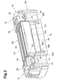
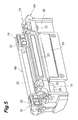
- the optical fiber reinforcing heating device 6A farther from the fusion splicer 4 has a base part 12 as illustrated in Figs. 3 to 6 .
- the base part 12 constitutes a housing of the optical fiber reinforcing heating device 6A and is formed so as to extend not only over the bottom face part of the optical fiber reinforcing heating device 6A but also to side face parts and the like thereof.
- the base part 12 may be constructed by a member different from the housing 2 or integrated with the housing 2.
- the base part 12 is formed with a sleeve accommodation groove 13 that contains a fiber reinforcement sleeve 5.
- the fiber reinforcement sleeve 5 is constituted by a heat-shrinkable tube 14 and a tension member 15 and an inner tube 16 which are arranged within the heat-shrinkable tube 14.
- the tension member 15 is made of a metal, glass, or the like.
- the inner tube 16 is formed from a hot-melt resin. As the heat-shrinkable tube 14 and inner tube 16, several kinds of those having different sizes and forms are used.
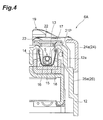
- the sleeve accommodation groove 13 is formed by an aluminum sheet 17 having a U-shaped cross section.
- a film heater 18 having a U-shaped cross section for heating the fiber reinforcement sleeve 5 contained in the sleeve accommodation groove 13 is attached to the rear face (outer surface) of the aluminum sheet 17. That is, the heater 18 extends along the bottom face and side faces of the sleeve accommodation groove 13. Using thus constructed heater 18 having a U-shaped cross section can effectively heat the fiber reinforcement sleeve 5.
- a pair of fiber holders 19 that holds and clamps the optical fibers 3 fusion-spliced by the fusion splicer 4 are disposed on both end sides of the sleeve accommodation groove 13.
- Each fiber holder 19 is constituted by a fiber accommodation part 20 that contains the optical fiber 3 and a lid part 22, attached openably and closably to the fiber accommodation part 20 through a rotary axis 21, which presses the optical fiber 3 against the fiber accommodation part 20.
- a lid part 23 that covers the sleeve accommodation groove 13 is attached openably and closably to the base part 12 through a rotary axis 21P.
- the lid part 23 is formed from a transparent resin or the like so that how the fiber reinforcement sleeve 5 shrinks can be seen visually, for example.
- a protector 24 for windbreak and heat insulation is joined to the lid part 23 through a rotary axis 25.
- the protector 24 has a board-like structure constructed by a main part 24a having an L-shaped cross section and a pair of sheet parts 24b disposed on both end sides of the main part 24a.
- a side face on the outside of the base part 12 is formed with a depressed guide 26 for guiding the protector 24.
- the depressed guide 26 is constituted by a depression 26a adapted to engage the main part 24a and a pair of depressions 26b formed deeper than the former depression 26a on both end sides of the depression 26a and adapted to engage the respective sheet parts 24b.
- the protector 24 descends along the depressed guide 26 while rotating with respect to the lid part 23 as illustrated in Figs. 5 and 6 . Therefore, the lid part 23 does not project sideways from the base part 12 even when opened, so that the optical fiber reinforcing heating device 6A is inhibited from increasing its size, whereby no large operation space is necessary.
- the optical fiber reinforcing heating device 6B closer to the fusion splicer 4 has substantially the same structure as with the optical fiber reinforcing heating device 6A except for the lack of the protector 24. Since the windproof cover 11 blocks winds when closed, the optical fiber reinforcing heating device 6B does not require the protector 24 in particular.
- a fusion-splicing operation using thus constructed optical fiber fusion-splicing device 1 is performed at an outdoor site.
- the fusion splicer 4 fusion-splices the two optical fibers 3 to each other. Specifically, one optical fiber 3 is passed through the fiber reinforcement sleeve 5. Subsequently, while the windproof cover 11 is open, the leading ends of the optical fibers 3 are butted against each other at the fiber positioning parts 9, and the fiber holder parts 8 hold and clamp the respective optical fibers 3. Then, the windproof cover 11 is closed, and the discharge electrodes 10 fuse the leading ends of the optical fibers 3 to each other by discharge.
- optical fiber reinforcing heating devices 6A, 6B heat and shrink the fiber reinforcement sleeve 5, thereby reinforcing the fusion-spliced part of the optical fibers 3.
- the optical fiber reinforcing heating devices 6A, 6B are used in this order.
- the fiber reinforcement sleeve 5 is moved to the fusion-splicing part of the optical fibers 3, so as to be contained in the sleeve accommodation groove 13 of the base part 12.
- the lid part 23 is closed, so as to cover and block the sleeve accommodation groove 13, and the lid parts 22 are closed, so as to press and clamp the optical fibers 3 to the fiber accommodation parts 20.
- the heater 18 is energized, so as to heat and shrink the fiber reinforcement sleeve 5.
- the protector 24 provided with the optical fiber reinforcing heating device 6A blocks winds from entering the sleeve accommodation groove 13 through a gap between the side wall 12a of the base part 12 and the lid part 23. This prevents winds from dissipating heat from the heater 18, whereby the fiber reinforcement sleeve 5 does not become harder to shrink.
- Heating the fiber reinforcement sleeve 5 with the heater 18 having a U-shaped cross section makes the side wall 12a of the base part 12 easier to become hotter. Since the protector 24 has an L-shaped cross section, however, a sufficient airspace (air layer) is secured between the side wall 12a and the protector 24, which makes it harder for the heat to transmit from the side wall 12a to the protector 24, whereby operators can be protected against the heat of the heater 18.
- the optical fiber reinforcing heating device 6B closer to the fusion splicer 4 thickening the side wall 12a of the base part 12 while providing the side wall 12a with an air layer makes it harder for the heat to transmit from the heater 18 to the side wall 12a, for example.
- forming the windproof cover 11 with a cutout corresponding to the increased thickness of the side wall 12a can keep the housing 2 from becoming larger in size.
- the protector 24 inhibits winds from entering the optical fiber reinforcing heating device 6A, whereby the winds are prevented from dissipating heat from the heater 18 in this embodiment. This can heat and shrink the fiber reinforcement sleeve 5 without taking a long time.
- the protector 24 effectively blocks the heat of the heater 18, the safety of operators can be secured without increasing the size of the optical fiber reinforcing heating device 6A in particular.
- the present invention is not limited to the above-mentioned embodiment.
- the structure of the heater 18 is not limited thereto in particular; a sheet-shaped heater may be disposed on the bottom part of the sleeve accommodation groove 13, for instance. This suppresses the heating of the side wall 12a of the base part 12, whereby the protector 24 is not restricted to the one having the L-shaped cross section in particular.
- optical fiber fusion-splicing device 1 of the above-mentioned embodiment is provided with one each of the optical fiber reinforcing heating devices 6A, 6B, this is not restrictive; only one optical fiber reinforcing heating device 6A or one optical fiber reinforcing heating device 6A and a plurality of optical fiber reinforcing heating devices 6B may be provided, for example.
Landscapes
- Physics & Mathematics (AREA)
- General Physics & Mathematics (AREA)
- Optics & Photonics (AREA)
- Engineering & Computer Science (AREA)
- Plasma & Fusion (AREA)
- Mechanical Coupling Of Light Guides (AREA)
Applications Claiming Priority (2)
| Application Number | Priority Date | Filing Date | Title |
|---|---|---|---|
| JP2010288403A JP5309403B2 (ja) | 2010-12-24 | 2010-12-24 | 光ファイバ補強用加熱器及び光ファイバ融着接続装置 |
| PCT/JP2011/079244 WO2012086556A1 (ja) | 2010-12-24 | 2011-12-16 | 光ファイバ補強用加熱器及び光ファイバ融着接続装置 |
Publications (3)
| Publication Number | Publication Date |
|---|---|
| EP2657737A1 true EP2657737A1 (de) | 2013-10-30 |
| EP2657737A4 EP2657737A4 (de) | 2015-01-21 |
| EP2657737B1 EP2657737B1 (de) | 2017-07-26 |
Family
ID=46313828
Family Applications (1)
| Application Number | Title | Priority Date | Filing Date |
|---|---|---|---|
| EP11851583.2A Active EP2657737B1 (de) | 2010-12-24 | 2011-12-16 | Heizvorrichtung zur glasfaserverstärkung und glasfaser-fusionsspleissvorrichtung |
Country Status (6)
| Country | Link |
|---|---|
| US (1) | US8950955B2 (de) |
| EP (1) | EP2657737B1 (de) |
| JP (1) | JP5309403B2 (de) |
| KR (1) | KR101819784B1 (de) |
| CN (1) | CN103270441B (de) |
| WO (1) | WO2012086556A1 (de) |
Families Citing this family (12)
| Publication number | Priority date | Publication date | Assignee | Title |
|---|---|---|---|---|
| GB2504465A (en) * | 2012-07-04 | 2014-02-05 | Haloblaze Ltd | Heating stations for heating heat-shrink tubing surrounding a cable |
| KR101692882B1 (ko) * | 2013-03-25 | 2017-01-04 | 가부시키가이샤후지쿠라 | 광섬유 접속부 보강 가열 장치 |
| USD746885S1 (en) * | 2013-10-30 | 2016-01-05 | Sei Optifrontier Co., Ltd. | Optical fiber fusion splicer |
| WO2016013438A1 (ja) * | 2014-07-25 | 2016-01-28 | 三菱電機株式会社 | 磁気センサ装置およびその製造方法 |
| USD795316S1 (en) * | 2014-08-08 | 2017-08-22 | Cullen Raichart | Bud trimmer |
| JP6628247B2 (ja) * | 2016-05-19 | 2020-01-08 | Seiオプティフロンティア株式会社 | 光ファイバ融着接続部の補強装置およびそれを備えた融着接続機 |
| JP1582501S (de) * | 2017-01-12 | 2017-07-31 | ||
| WO2019124218A1 (ja) | 2017-12-22 | 2019-06-27 | Seiオプティフロンティア株式会社 | 融着接続装置、無線情報端末、融着接続システム、及び融着接続方法 |
| US11409042B2 (en) * | 2018-10-02 | 2022-08-09 | Sumitomo Electric Optifrontier Co., Ltd. | Reinforcement device for optical fiber fusion splicing section and fusion splicer provided with same |
| US11016247B2 (en) | 2018-10-11 | 2021-05-25 | Senko Advanced Components Inc | Mechanical splice protective sleeve for securing a splice area formed by splicing a plural of optical fibers |
| JP7568184B2 (ja) | 2019-01-30 | 2024-10-16 | 住友電工オプティフロンティア株式会社 | 補強用スリーブ加熱装置及び融着接続機 |
| JPWO2022030403A1 (de) | 2020-08-07 | 2022-02-10 |
Family Cites Families (11)
| Publication number | Priority date | Publication date | Assignee | Title |
|---|---|---|---|---|
| SE9901493D0 (sv) * | 1999-04-26 | 1999-04-26 | Ericsson Telefon Ab L M | Fibersvetsningsapparat med uppvärmningsanordning |
| JP2003270476A (ja) * | 2002-03-14 | 2003-09-25 | Fujikura Ltd | 熱収縮スリーブ用加熱装置 |
| US7212718B2 (en) * | 2003-11-12 | 2007-05-01 | Sumitomo Electric Industries, Ltd. | Apparatus and method for heat-treatment of optical fiber reinforcing member and optical fiber fusion splicing apparatus |
| JP4477526B2 (ja) * | 2005-03-10 | 2010-06-09 | 古河電気工業株式会社 | 光ファイバ融着接続部の補強用加熱装置および補強方法 |
| JP2007065026A (ja) | 2005-08-29 | 2007-03-15 | Furukawa Electric Co Ltd:The | 熱収縮スリーブ加熱装置、それを用いた光ファイバ融着接続機、及び光ファイバ融着接続補強方法 |
| JP4752730B2 (ja) * | 2006-11-07 | 2011-08-17 | 住友電気工業株式会社 | 光ファイバの加熱補強処理装置及び光ファイバ融着接続装置 |
| JP5277962B2 (ja) * | 2006-11-13 | 2013-08-28 | 住友電気工業株式会社 | ホルダ及び融着接続機及び光コネクタの組立方法 |
| US7467899B2 (en) * | 2007-01-31 | 2008-12-23 | The Furukawa Electric Co., Ltd. | Ferrule transfer method and ferrule holder |
| US7955004B2 (en) * | 2008-09-04 | 2011-06-07 | Fibersource, Inc. | Fiber optic furcation method |
| JP2010249967A (ja) * | 2009-04-14 | 2010-11-04 | Sumitomo Electric Ind Ltd | ホルダ、融着接続機及び融着接続方法 |
| US7901147B1 (en) * | 2010-02-26 | 2011-03-08 | Corning Cable Systems Llc | Splice protector installation tool and method of use |
-
2010
- 2010-12-24 JP JP2010288403A patent/JP5309403B2/ja active Active
-
2011
- 2011-12-16 WO PCT/JP2011/079244 patent/WO2012086556A1/ja not_active Ceased
- 2011-12-16 US US13/995,968 patent/US8950955B2/en active Active
- 2011-12-16 KR KR1020137019127A patent/KR101819784B1/ko active Active
- 2011-12-16 EP EP11851583.2A patent/EP2657737B1/de active Active
- 2011-12-16 CN CN201180062470.5A patent/CN103270441B/zh active Active
Also Published As
| Publication number | Publication date |
|---|---|
| US8950955B2 (en) | 2015-02-10 |
| JP5309403B2 (ja) | 2013-10-09 |
| EP2657737A4 (de) | 2015-01-21 |
| KR20140004684A (ko) | 2014-01-13 |
| EP2657737B1 (de) | 2017-07-26 |
| CN103270441B (zh) | 2015-09-30 |
| WO2012086556A1 (ja) | 2012-06-28 |
| JP2012137543A (ja) | 2012-07-19 |
| CN103270441A (zh) | 2013-08-28 |
| KR101819784B1 (ko) | 2018-01-17 |
| US20130315544A1 (en) | 2013-11-28 |
Similar Documents
| Publication | Publication Date | Title |
|---|---|---|
| EP2657737B1 (de) | Heizvorrichtung zur glasfaserverstärkung und glasfaser-fusionsspleissvorrichtung | |
| EP2241914B1 (de) | Glasfaserkabelhalter, Fusionsspleißer mit dem Halter und Fusionsspleißverfahren mittels des Halters | |
| US8992101B2 (en) | Heating device for optical-fiber reinforcement, and optical-fiber fusion splicing device | |
| US9004781B2 (en) | Method for reinforcing a splice part and reinforcing structure | |
| EP2660633B1 (de) | Glasfaserhalter und glasfaser-fusionsverbindungsvorrichtung | |
| JP6628247B2 (ja) | 光ファイバ融着接続部の補強装置およびそれを備えた融着接続機 | |
| CN102349011A (zh) | 光纤支架以及熔接机 | |
| US11204465B2 (en) | Optical fiber holder and fusion-splicing apparatus including optical fiber holder | |
| JP5136631B2 (ja) | ファイバホルダ | |
| US20220155523A1 (en) | Reinforcement sleeve heating device and fusion splicing machine | |
| JP2013114135A (ja) | 光ファイバ融着接続部の補強装置及び融着接続機 | |
| SE0004394L (sv) | Slutet utrymme för skarvar på optofiberkablar |
Legal Events
| Date | Code | Title | Description |
|---|---|---|---|
| PUAI | Public reference made under article 153(3) epc to a published international application that has entered the european phase |
Free format text: ORIGINAL CODE: 0009012 |
|
| 17P | Request for examination filed |
Effective date: 20130709 |
|
| AK | Designated contracting states |
Kind code of ref document: A1 Designated state(s): AL AT BE BG CH CY CZ DE DK EE ES FI FR GB GR HR HU IE IS IT LI LT LU LV MC MK MT NL NO PL PT RO RS SE SI SK SM TR |
|
| DAX | Request for extension of the european patent (deleted) | ||
| A4 | Supplementary search report drawn up and despatched |
Effective date: 20141222 |
|
| RIC1 | Information provided on ipc code assigned before grant |
Ipc: G02B 6/255 20060101AFI20141216BHEP |
|
| GRAP | Despatch of communication of intention to grant a patent |
Free format text: ORIGINAL CODE: EPIDOSNIGR1 |
|
| INTG | Intention to grant announced |
Effective date: 20170208 |
|
| GRAS | Grant fee paid |
Free format text: ORIGINAL CODE: EPIDOSNIGR3 |
|
| GRAJ | Information related to disapproval of communication of intention to grant by the applicant or resumption of examination proceedings by the epo deleted |
Free format text: ORIGINAL CODE: EPIDOSDIGR1 |
|
| GRAL | Information related to payment of fee for publishing/printing deleted |
Free format text: ORIGINAL CODE: EPIDOSDIGR3 |
|
| GRAR | Information related to intention to grant a patent recorded |
Free format text: ORIGINAL CODE: EPIDOSNIGR71 |
|
| GRAA | (expected) grant |
Free format text: ORIGINAL CODE: 0009210 |
|
| INTC | Intention to grant announced (deleted) | ||
| AK | Designated contracting states |
Kind code of ref document: B1 Designated state(s): AL AT BE BG CH CY CZ DE DK EE ES FI FR GB GR HR HU IE IS IT LI LT LU LV MC MK MT NL NO PL PT RO RS SE SI SK SM TR |
|
| INTG | Intention to grant announced |
Effective date: 20170620 |
|
| REG | Reference to a national code |
Ref country code: GB Ref legal event code: FG4D |
|
| REG | Reference to a national code |
Ref country code: CH Ref legal event code: EP |
|
| REG | Reference to a national code |
Ref country code: AT Ref legal event code: REF Ref document number: 912835 Country of ref document: AT Kind code of ref document: T Effective date: 20170815 |
|
| REG | Reference to a national code |
Ref country code: IE Ref legal event code: FG4D |
|
| REG | Reference to a national code |
Ref country code: DE Ref legal event code: R096 Ref document number: 602011040027 Country of ref document: DE |
|
| REG | Reference to a national code |
Ref country code: NL Ref legal event code: MP Effective date: 20170726 |
|
| REG | Reference to a national code |
Ref country code: LT Ref legal event code: MG4D |
|
| REG | Reference to a national code |
Ref country code: AT Ref legal event code: MK05 Ref document number: 912835 Country of ref document: AT Kind code of ref document: T Effective date: 20170726 |
|
| PG25 | Lapsed in a contracting state [announced via postgrant information from national office to epo] |
Ref country code: SE Free format text: LAPSE BECAUSE OF FAILURE TO SUBMIT A TRANSLATION OF THE DESCRIPTION OR TO PAY THE FEE WITHIN THE PRESCRIBED TIME-LIMIT Effective date: 20170726 Ref country code: FI Free format text: LAPSE BECAUSE OF FAILURE TO SUBMIT A TRANSLATION OF THE DESCRIPTION OR TO PAY THE FEE WITHIN THE PRESCRIBED TIME-LIMIT Effective date: 20170726 Ref country code: AT Free format text: LAPSE BECAUSE OF FAILURE TO SUBMIT A TRANSLATION OF THE DESCRIPTION OR TO PAY THE FEE WITHIN THE PRESCRIBED TIME-LIMIT Effective date: 20170726 Ref country code: NL Free format text: LAPSE BECAUSE OF FAILURE TO SUBMIT A TRANSLATION OF THE DESCRIPTION OR TO PAY THE FEE WITHIN THE PRESCRIBED TIME-LIMIT Effective date: 20170726 Ref country code: HR Free format text: LAPSE BECAUSE OF FAILURE TO SUBMIT A TRANSLATION OF THE DESCRIPTION OR TO PAY THE FEE WITHIN THE PRESCRIBED TIME-LIMIT Effective date: 20170726 Ref country code: NO Free format text: LAPSE BECAUSE OF FAILURE TO SUBMIT A TRANSLATION OF THE DESCRIPTION OR TO PAY THE FEE WITHIN THE PRESCRIBED TIME-LIMIT Effective date: 20171026 Ref country code: LT Free format text: LAPSE BECAUSE OF FAILURE TO SUBMIT A TRANSLATION OF THE DESCRIPTION OR TO PAY THE FEE WITHIN THE PRESCRIBED TIME-LIMIT Effective date: 20170726 |
|
| PG25 | Lapsed in a contracting state [announced via postgrant information from national office to epo] |
Ref country code: GR Free format text: LAPSE BECAUSE OF FAILURE TO SUBMIT A TRANSLATION OF THE DESCRIPTION OR TO PAY THE FEE WITHIN THE PRESCRIBED TIME-LIMIT Effective date: 20171027 Ref country code: PL Free format text: LAPSE BECAUSE OF FAILURE TO SUBMIT A TRANSLATION OF THE DESCRIPTION OR TO PAY THE FEE WITHIN THE PRESCRIBED TIME-LIMIT Effective date: 20170726 Ref country code: RS Free format text: LAPSE BECAUSE OF FAILURE TO SUBMIT A TRANSLATION OF THE DESCRIPTION OR TO PAY THE FEE WITHIN THE PRESCRIBED TIME-LIMIT Effective date: 20170726 Ref country code: IS Free format text: LAPSE BECAUSE OF FAILURE TO SUBMIT A TRANSLATION OF THE DESCRIPTION OR TO PAY THE FEE WITHIN THE PRESCRIBED TIME-LIMIT Effective date: 20171126 Ref country code: ES Free format text: LAPSE BECAUSE OF FAILURE TO SUBMIT A TRANSLATION OF THE DESCRIPTION OR TO PAY THE FEE WITHIN THE PRESCRIBED TIME-LIMIT Effective date: 20170726 Ref country code: BG Free format text: LAPSE BECAUSE OF FAILURE TO SUBMIT A TRANSLATION OF THE DESCRIPTION OR TO PAY THE FEE WITHIN THE PRESCRIBED TIME-LIMIT Effective date: 20171026 Ref country code: LV Free format text: LAPSE BECAUSE OF FAILURE TO SUBMIT A TRANSLATION OF THE DESCRIPTION OR TO PAY THE FEE WITHIN THE PRESCRIBED TIME-LIMIT Effective date: 20170726 |
|
| PG25 | Lapsed in a contracting state [announced via postgrant information from national office to epo] |
Ref country code: CZ Free format text: LAPSE BECAUSE OF FAILURE TO SUBMIT A TRANSLATION OF THE DESCRIPTION OR TO PAY THE FEE WITHIN THE PRESCRIBED TIME-LIMIT Effective date: 20170726 Ref country code: RO Free format text: LAPSE BECAUSE OF FAILURE TO SUBMIT A TRANSLATION OF THE DESCRIPTION OR TO PAY THE FEE WITHIN THE PRESCRIBED TIME-LIMIT Effective date: 20170726 Ref country code: DK Free format text: LAPSE BECAUSE OF FAILURE TO SUBMIT A TRANSLATION OF THE DESCRIPTION OR TO PAY THE FEE WITHIN THE PRESCRIBED TIME-LIMIT Effective date: 20170726 |
|
| REG | Reference to a national code |
Ref country code: DE Ref legal event code: R097 Ref document number: 602011040027 Country of ref document: DE |
|
| PG25 | Lapsed in a contracting state [announced via postgrant information from national office to epo] |
Ref country code: SK Free format text: LAPSE BECAUSE OF FAILURE TO SUBMIT A TRANSLATION OF THE DESCRIPTION OR TO PAY THE FEE WITHIN THE PRESCRIBED TIME-LIMIT Effective date: 20170726 Ref country code: EE Free format text: LAPSE BECAUSE OF FAILURE TO SUBMIT A TRANSLATION OF THE DESCRIPTION OR TO PAY THE FEE WITHIN THE PRESCRIBED TIME-LIMIT Effective date: 20170726 Ref country code: IT Free format text: LAPSE BECAUSE OF FAILURE TO SUBMIT A TRANSLATION OF THE DESCRIPTION OR TO PAY THE FEE WITHIN THE PRESCRIBED TIME-LIMIT Effective date: 20170726 Ref country code: SM Free format text: LAPSE BECAUSE OF FAILURE TO SUBMIT A TRANSLATION OF THE DESCRIPTION OR TO PAY THE FEE WITHIN THE PRESCRIBED TIME-LIMIT Effective date: 20170726 |
|
| PLBE | No opposition filed within time limit |
Free format text: ORIGINAL CODE: 0009261 |
|
| STAA | Information on the status of an ep patent application or granted ep patent |
Free format text: STATUS: NO OPPOSITION FILED WITHIN TIME LIMIT |
|
| REG | Reference to a national code |
Ref country code: DE Ref legal event code: R119 Ref document number: 602011040027 Country of ref document: DE |
|
| 26N | No opposition filed |
Effective date: 20180430 |
|
| REG | Reference to a national code |
Ref country code: CH Ref legal event code: PL |
|
| PG25 | Lapsed in a contracting state [announced via postgrant information from national office to epo] |
Ref country code: SI Free format text: LAPSE BECAUSE OF FAILURE TO SUBMIT A TRANSLATION OF THE DESCRIPTION OR TO PAY THE FEE WITHIN THE PRESCRIBED TIME-LIMIT Effective date: 20170726 |
|
| REG | Reference to a national code |
Ref country code: IE Ref legal event code: MM4A |
|
| PG25 | Lapsed in a contracting state [announced via postgrant information from national office to epo] |
Ref country code: LU Free format text: LAPSE BECAUSE OF NON-PAYMENT OF DUE FEES Effective date: 20171216 Ref country code: MT Free format text: LAPSE BECAUSE OF NON-PAYMENT OF DUE FEES Effective date: 20171216 |
|
| REG | Reference to a national code |
Ref country code: FR Ref legal event code: ST Effective date: 20180831 |
|
| REG | Reference to a national code |
Ref country code: BE Ref legal event code: MM Effective date: 20171231 |
|
| PG25 | Lapsed in a contracting state [announced via postgrant information from national office to epo] |
Ref country code: IE Free format text: LAPSE BECAUSE OF NON-PAYMENT OF DUE FEES Effective date: 20171216 Ref country code: FR Free format text: LAPSE BECAUSE OF NON-PAYMENT OF DUE FEES Effective date: 20180102 Ref country code: DE Free format text: LAPSE BECAUSE OF NON-PAYMENT OF DUE FEES Effective date: 20180703 |
|
| PG25 | Lapsed in a contracting state [announced via postgrant information from national office to epo] |
Ref country code: LI Free format text: LAPSE BECAUSE OF NON-PAYMENT OF DUE FEES Effective date: 20171231 Ref country code: BE Free format text: LAPSE BECAUSE OF NON-PAYMENT OF DUE FEES Effective date: 20171231 Ref country code: CH Free format text: LAPSE BECAUSE OF NON-PAYMENT OF DUE FEES Effective date: 20171231 |
|
| PG25 | Lapsed in a contracting state [announced via postgrant information from national office to epo] |
Ref country code: MC Free format text: LAPSE BECAUSE OF FAILURE TO SUBMIT A TRANSLATION OF THE DESCRIPTION OR TO PAY THE FEE WITHIN THE PRESCRIBED TIME-LIMIT Effective date: 20170726 Ref country code: HU Free format text: LAPSE BECAUSE OF FAILURE TO SUBMIT A TRANSLATION OF THE DESCRIPTION OR TO PAY THE FEE WITHIN THE PRESCRIBED TIME-LIMIT; INVALID AB INITIO Effective date: 20111216 |
|
| PG25 | Lapsed in a contracting state [announced via postgrant information from national office to epo] |
Ref country code: CY Free format text: LAPSE BECAUSE OF NON-PAYMENT OF DUE FEES Effective date: 20170726 |
|
| PG25 | Lapsed in a contracting state [announced via postgrant information from national office to epo] |
Ref country code: MK Free format text: LAPSE BECAUSE OF FAILURE TO SUBMIT A TRANSLATION OF THE DESCRIPTION OR TO PAY THE FEE WITHIN THE PRESCRIBED TIME-LIMIT Effective date: 20170726 |
|
| PG25 | Lapsed in a contracting state [announced via postgrant information from national office to epo] |
Ref country code: TR Free format text: LAPSE BECAUSE OF FAILURE TO SUBMIT A TRANSLATION OF THE DESCRIPTION OR TO PAY THE FEE WITHIN THE PRESCRIBED TIME-LIMIT Effective date: 20170726 |
|
| PG25 | Lapsed in a contracting state [announced via postgrant information from national office to epo] |
Ref country code: PT Free format text: LAPSE BECAUSE OF FAILURE TO SUBMIT A TRANSLATION OF THE DESCRIPTION OR TO PAY THE FEE WITHIN THE PRESCRIBED TIME-LIMIT Effective date: 20170726 |
|
| PG25 | Lapsed in a contracting state [announced via postgrant information from national office to epo] |
Ref country code: AL Free format text: LAPSE BECAUSE OF FAILURE TO SUBMIT A TRANSLATION OF THE DESCRIPTION OR TO PAY THE FEE WITHIN THE PRESCRIBED TIME-LIMIT Effective date: 20170726 |
|
| PGFP | Annual fee paid to national office [announced via postgrant information from national office to epo] |
Ref country code: GB Payment date: 20251030 Year of fee payment: 15 |