EP2657786A2 - Dispositif de développement, cartouche de traitement et appareil de formation dýimages - Google Patents
Dispositif de développement, cartouche de traitement et appareil de formation dýimages Download PDFInfo
- Publication number
- EP2657786A2 EP2657786A2 EP13162723.4A EP13162723A EP2657786A2 EP 2657786 A2 EP2657786 A2 EP 2657786A2 EP 13162723 A EP13162723 A EP 13162723A EP 2657786 A2 EP2657786 A2 EP 2657786A2
- Authority
- EP
- European Patent Office
- Prior art keywords
- toner
- supply
- developer
- bearing member
- supply roller
- Prior art date
- Legal status (The legal status is an assumption and is not a legal conclusion. Google has not performed a legal analysis and makes no representation as to the accuracy of the status listed.)
- Granted
Links
Images








Classifications
-
- G—PHYSICS
- G03—PHOTOGRAPHY; CINEMATOGRAPHY; ANALOGOUS TECHNIQUES USING WAVES OTHER THAN OPTICAL WAVES; ELECTROGRAPHY; HOLOGRAPHY
- G03G—ELECTROGRAPHY; ELECTROPHOTOGRAPHY; MAGNETOGRAPHY
- G03G21/00—Arrangements not provided for by groups G03G13/00 - G03G19/00, e.g. cleaning, elimination of residual charge
- G03G21/16—Mechanical means for facilitating the maintenance of the apparatus, e.g. modular arrangements
- G03G21/18—Mechanical means for facilitating the maintenance of the apparatus, e.g. modular arrangements using a processing cartridge, whereby the process cartridge comprises at least two image processing means in a single unit
-
- G—PHYSICS
- G03—PHOTOGRAPHY; CINEMATOGRAPHY; ANALOGOUS TECHNIQUES USING WAVES OTHER THAN OPTICAL WAVES; ELECTROGRAPHY; HOLOGRAPHY
- G03G—ELECTROGRAPHY; ELECTROPHOTOGRAPHY; MAGNETOGRAPHY
- G03G15/00—Apparatus for electrographic processes using a charge pattern
- G03G15/06—Apparatus for electrographic processes using a charge pattern for developing
- G03G15/08—Apparatus for electrographic processes using a charge pattern for developing using a solid developer, e.g. powder developer
-
- G—PHYSICS
- G03—PHOTOGRAPHY; CINEMATOGRAPHY; ANALOGOUS TECHNIQUES USING WAVES OTHER THAN OPTICAL WAVES; ELECTROGRAPHY; HOLOGRAPHY
- G03G—ELECTROGRAPHY; ELECTROPHOTOGRAPHY; MAGNETOGRAPHY
- G03G15/00—Apparatus for electrographic processes using a charge pattern
- G03G15/06—Apparatus for electrographic processes using a charge pattern for developing
- G03G15/08—Apparatus for electrographic processes using a charge pattern for developing using a solid developer, e.g. powder developer
- G03G15/0806—Apparatus for electrographic processes using a charge pattern for developing using a solid developer, e.g. powder developer on a donor element, e.g. belt, roller
- G03G15/0808—Apparatus for electrographic processes using a charge pattern for developing using a solid developer, e.g. powder developer on a donor element, e.g. belt, roller characterised by the developer supplying means, e.g. structure of developer supply roller
-
- G—PHYSICS
- G03—PHOTOGRAPHY; CINEMATOGRAPHY; ANALOGOUS TECHNIQUES USING WAVES OTHER THAN OPTICAL WAVES; ELECTROGRAPHY; HOLOGRAPHY
- G03G—ELECTROGRAPHY; ELECTROPHOTOGRAPHY; MAGNETOGRAPHY
- G03G2215/00—Apparatus for electrophotographic processes
- G03G2215/08—Details of powder developing device not concerning the development directly
- G03G2215/0802—Arrangements for agitating or circulating developer material
- G03G2215/0808—Donor member rotation direction
- G03G2215/0813—Lower part of donor member transports used developer back to the sump
-
- G—PHYSICS
- G03—PHOTOGRAPHY; CINEMATOGRAPHY; ANALOGOUS TECHNIQUES USING WAVES OTHER THAN OPTICAL WAVES; ELECTROGRAPHY; HOLOGRAPHY
- G03G—ELECTROGRAPHY; ELECTROPHOTOGRAPHY; MAGNETOGRAPHY
- G03G2215/00—Apparatus for electrophotographic processes
- G03G2215/08—Details of powder developing device not concerning the development directly
- G03G2215/0802—Arrangements for agitating or circulating developer material
- G03G2215/0836—Way of functioning of agitator means
- G03G2215/0841—Presentation of developer to donor member
- G03G2215/0844—Presentation of developer to donor member by upward movement of agitator member
Definitions
- the present invention relates to an image forming apparatus configured to form an image on a recording material using an electrophotographic method, and more particularly, to a developing device and a process cartridge that are applied to the image forming apparatus.
- a fixing device and a developing device can be arranged at a distant, for example, in such a manner that the intermediate transfer member or the recording material bearing member is sandwiched therebetween within an image forming apparatus main body. Therefore, the developing device (or the exposure device) is not easily affected by heat from the fixing device.
- Fig. 1 is a schematic sectional view illustrating a configuration of an image forming apparatus according to a first exemplary embodiment.
- Fig. 8 is a schematic sectional view illustrating a configuration of an image forming apparatus according to each of third and fourth exemplary embodiments.
- Fig. 9 is a schematic sectional view illustrating a configuration of a process cartridge according to each of the third and fourth exemplary embodiments.
- Fig. 12 illustrates an amount of a toner coat on a developing roller which has been rubbed with a supply roller relative to the ratio of respective peripheral speeds of the developing roller and the supply roller.
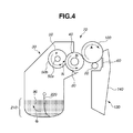
- the developing roller 40 and the photosensitive drum 100 respectively rotate so that their respective surfaces move in the same direction (a direction directed upward from below according to the present exemplary embodiment) at a facing portion (contact portion) therebetween.
- the toner conveyance member 220, the developing roller 40, and the supply roller 50 rotate upon receiving a driving force from a developing unit driving motor (not illustrated) provided in the image forming apparatus main body.
- the developing roller 40 is arranged in contact with the photosensitive drum 100 according to the present exemplary embodiment, the developing roller 40 may be closely arranged at a predetermined interval from the photosensitive drum 100.
- the supply roller 50 rotates with a nip portion N formed between the supply roller 50 and the developing roller 40.
- the nip portion N is a portion where toner is nipped between the developing roller 40 and the supply roller 50.
- the supply roller 50 is an elastic sponge roller having a foam layer formed on an outer periphery of its conductive core.
- the supply roller 50 and the developing roller 40 contact each other by a predetermined amount of intrusion, i.e., a concave amount ⁇ E which is generated when the developing roller 40 deforms the supply roller 50 in a concave shape in Fig. 3 .
- a part of the toner stored in the temporary toner storage portion V enters the nip portion N by rotation of the developing roller 40 and the supply roller 50.
- a charge is applied to the toner which has entered the nip portion N by sliding friction between the developing roller 40 and the supply roller 50.
- the charged toner is electrostatically adsorbed to the developing roller 40 due to its own charge amount after passing through the nip portion N. Due to the effect, the toner is supplied from the supply roller 50 to the developing roller 40.
- the regulating blade (regulating member) 80 regulates a part of the toner which has been supplied to the developing roller 40 to form a toner coat having a desired layer thickness on the developing roller 40.
- the regulated toner drops by gravity and returns to the toner containing unit 210.
- the outer diameter of the developing roller 40 is 12 mm, and the outer diameter of the supply roller 50 is 15 mm, as described above.
- a similar experiment to the above-described experiment was performed for a configuration in which the outer diameter of the developing roller 40 was 12 mm and the outer diameter of the supply roller 50 was 7 mm.
- a more satisfactory result was obtained when the outer diameter of the supply roller 50 was 15 mm. This result can be caused by an increase in the volume of the temporary toner storage portion V by making the outer diameter of the supply roller 50 larger than the outer diameter of the developing roller 40.
- toner which has been ejected from the foam layer on the supply roller 50 is stored in the temporary toner storage portion V and contributes to the decrease in density of the solid image.
- the foam layer is not a component essential in producing the effect of the present invention. More specifically, if the supply roller 50 forming the nip portion N between the supply roller 50 and the developing roller 40 rotates in the direction from the upper end to the lower end of the nip portion N, the toner supplied from the toner conveyance member 220 is stored above the nip portion N so that the decrease in density of the solid image can be suppressed in a simple configuration.
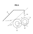
- a relationship between the arrangement of the supply roller 50 and the developing roller 40 and the temporary toner storage portion V will be described below.
- an angle ⁇ 2 between a common tangential line on the upstream side of rotation (the upper common tangential lines to the supply roller 50 and the developing roller 40) and a horizontal line was used as a value representing a relationship between the supply roller 50 and the developing roller 40.
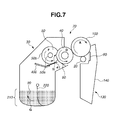
- the size of the temporary toner storage portion V was changed by changing the outer diameter of the supply roller 50 and the arrangement of the supply roller 50, to evaluate density stability of a solid image similar to that according to the first exemplary embodiment.
- Fig. 8 is a schematic view illustrating a configuration of an image forming apparatus according to a third exemplary embodiment.
- the electrostatic latent image is then developed by a developing unit 10b (a developing device) and visualized as a toner image.
- a contact development method is used.
- toner charged to a negative polarity in a contact area between a supply roller 8 and the developing roller 7 and a contact area between a regulating blade 11 and the developing roller 7 is applied to the electrostatic latent image on the photosensitive drum surface by applying a DC development bias voltage to the developing roller 7 from the development bias power source, so that the electrostatic latent image is reversely developed.
- the image forming apparatus uses the above-described units, and repeats the processes such as charging, exposure, development, transfer, fixing, and cleaning, to perform image formation.
- the toner layer on the developing roller 7 is transferred to an electrostatic latent image on the photosensitive drum 1 by a development electric field, and the electrostatic latent image is visualized as a toner image.
- the toner image is then separated from the photosensitive drum 1 to reach an intermediate transfer member 12, and a cleaning blade 9 scrapes transfer residual toner from the photosensitive drum 1 to clean the photosensitive drum surface, and the processing proceeds to the charging process again.
- the toner layer remaining on the developing roller 7 without being used for development in the development region is scraped from the developing roller 7 at an abutment portion between the developing roller 7 and the supply roller 8. Simultaneously, toner is newly supplied onto the developing roller 7 by rotation of the supply roller 8.
- the toner which has been scraped by the supply roller 8 is returned into the development container 5 by rotation of the supply roller 8, and is agitated and mixed within the development container 5.
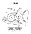
- a range of 0 ⁇ V RS /V DR ⁇ 1.0 represents a rotational state where the developing roller 7 and the supply roller 8 rotate (rotate in a forward direction) so that their respective surfaces move in the same direction in the nip portion N at a low speed.
- a range of 1.0 ⁇ V RS /V DR represents a state where the supply roller 8 rotates in a forward direction at a higher speed than that of the developing roller 7.
- the supply roller 8 and the developing roller 7 are rotated in the forward direction in the range of 1.0 ⁇ V RS /V DR , so that the charge amount of the toner increases and the supply amount of the toner can be increased using the supply bias more effectively.
- Fig. 12 illustrates an amount of a toner coat on the developing roller 7 at a position after sliding friction with the supply roller 8 and before regulation by the regulating blade 11 relative to a peripheral speed ratio between the developing roller 7 and the supply roller 8.
- the amount of the toner coat on the developing roller 7 after sliding friction with the supply roller 8 is below 1.0 [mg/cm 2 ] in the range of 1.0 ⁇ V RS /V DR ⁇ 1.5. If a solid image is developed in this state, the amount of the toner coat on the developing roller 7 differs between the first round and the second round of the developing roller 7, so that a ghost image easily appears.
- Toner contained in a toner containing unit is splashed by an agitation sheet 4a, and its large part is conveyed to the upper part of the supply roller 8.
- the toner which has been conveyed to the supply roller 8 remains on a surface and inside of the supply roller 8.
- the toner is conveyed right in front of the nip portion N between the supply roller 8 and the developing roller 7 by the rotation of the supply roller 8 in the direction indicated by the arrow E illustrated in Figs. 9 and 13 .
- the supply roller 8 is deformed right in front of the nip portion N between the supply roller 8 and the developing roller 7.
- the toner is supplied from the supplying roller 8 to the developing roller 7.
- a regulating member 11 regulates a part of the toner which has been supplied to the developing roller 7 to form a toner coat having a desired layer thickness on the developing roller 7.
- the regulated toner drops by gravity and returns to the toner containing unit 210.
- a sufficient amount of toner needs to enter the nip portion N from the temporary toner storage portion V, and a sufficient amount of charge needs to be applied to the toner by sliding friction with the supply roller 8 when the toner passes through the nip portion N.
- An amount of intrusion X mm of the supply roller 8 to the developing roller 7 desirably satisfies 0.25 mm ⁇ X mm ⁇ 1.8 mm.
- X mm ⁇ 0.25 mm an abutment pressure between the supply roller 8 and the developing roller 7 becomes low, so that their respective forces of sliding friction with toner become small.
- a charge application capability to the toner due to sliding friction with the supply roller 8 becomes insufficient under this condition.
- DC biases E DR and E RS are respectively applied to the developing roller 7 and the supply roller 8. It is desirable that the DC biases E DR and E RS can satisfy E RS ⁇ E DR .
- E RS > E DR toner which has obtained a charge by sliding friction with the supply roller 8 is drawn toward the supply roller 8 by an electric field generated therein. More specifically, in such setting, the supply of the toner to the developing roller 7 runs short, so that a poor solid follow-up performance occurs.
- the effect of the present invention is not limited to this setting. If E RS ⁇ E DR is satisfied, a similar effect can be obtained.
- Results of the experiment will be described below. Similar experiments were conducted by a comparison configuration for comparing the effect of the present exemplary embodiment. Results for the comparison configuration will be described together with the result for the configuration according to the present exemplary embodiment.
Landscapes
- Physics & Mathematics (AREA)
- General Physics & Mathematics (AREA)
- Engineering & Computer Science (AREA)
- Computer Vision & Pattern Recognition (AREA)
- Dry Development In Electrophotography (AREA)
Applications Claiming Priority (2)
| Application Number | Priority Date | Filing Date | Title |
|---|---|---|---|
| JP2012100957 | 2012-04-26 | ||
| JP2012100955 | 2012-04-26 |
Publications (3)
| Publication Number | Publication Date |
|---|---|
| EP2657786A2 true EP2657786A2 (fr) | 2013-10-30 |
| EP2657786A3 EP2657786A3 (fr) | 2017-10-04 |
| EP2657786B1 EP2657786B1 (fr) | 2020-01-15 |
Family
ID=48082963
Family Applications (1)
| Application Number | Title | Priority Date | Filing Date |
|---|---|---|---|
| EP13162723.4A Active EP2657786B1 (fr) | 2012-04-26 | 2013-04-08 | Dispositif de développement, cartouche de traitement et appareil de formation d'images |
Country Status (4)
| Country | Link |
|---|---|
| US (2) | US9568855B2 (fr) |
| EP (1) | EP2657786B1 (fr) |
| JP (1) | JP6214166B2 (fr) |
| CN (2) | CN106125526B (fr) |
Families Citing this family (5)
| Publication number | Priority date | Publication date | Assignee | Title |
|---|---|---|---|---|
| US9696684B2 (en) | 2012-12-14 | 2017-07-04 | Canon Kabushiki Kaisha | Process cartridge and image forming apparatus |
| JP6242201B2 (ja) * | 2012-12-14 | 2017-12-06 | キヤノン株式会社 | プロセスカートリッジ及び画像形成装置 |
| JP6316034B2 (ja) * | 2014-03-14 | 2018-04-25 | キヤノン株式会社 | 画像形成装置 |
| JP7500279B2 (ja) * | 2020-06-01 | 2024-06-17 | キヤノン株式会社 | 現像装置、カートリッジ及び画像形成装置 |
| US12596325B2 (en) * | 2023-09-12 | 2026-04-07 | Canon Kabushiki Kaisha | Process cartridge |
Citations (1)
| Publication number | Priority date | Publication date | Assignee | Title |
|---|---|---|---|---|
| JP2003173083A (ja) | 2001-12-07 | 2003-06-20 | Seiko Epson Corp | 現像装置およびそれを用いた画像形成装置 |
Family Cites Families (42)
| Publication number | Priority date | Publication date | Assignee | Title |
|---|---|---|---|---|
| JPS5614260A (en) * | 1979-07-16 | 1981-02-12 | Canon Inc | Developing device |
| US5170213A (en) * | 1990-03-26 | 1992-12-08 | Japan Imaging System, Inc. | Developer unit utilizing a non-magnetic single component developer |
| JPH0744099A (ja) * | 1993-07-27 | 1995-02-14 | Sekisui House Ltd | インテリアの決定システム |
| JPH08220883A (ja) * | 1995-02-14 | 1996-08-30 | Tec Corp | 現像装置 |
| JP2001060037A (ja) * | 1995-09-12 | 2001-03-06 | Brother Ind Ltd | 画像形成装置 |
| JPH09319212A (ja) * | 1996-05-31 | 1997-12-12 | Mita Ind Co Ltd | 画像形成機の静電潜像現像装置 |
| US5839021A (en) * | 1996-07-24 | 1998-11-17 | Oki-Data Corporation | Developing unit for an electrophotographic printer employing a supply roller for transferring toner to a developing roller |
| JP3502554B2 (ja) * | 1998-02-04 | 2004-03-02 | シャープ株式会社 | 現像装置 |
| JPH11311899A (ja) * | 1998-04-30 | 1999-11-09 | Mita Ind Co Ltd | 画像形成装置 |
| US6196958B1 (en) * | 1998-06-05 | 2001-03-06 | Tokai Rubber Industries, Ltd. | Toner supply roll including cylindrical polyurethane sponge structure having helical protrusions on its outer surface |
| US5923932A (en) * | 1998-09-28 | 1999-07-13 | Xerox Corporation | Hybrid scavengeless development using a method for preventing a ghosting print defect |
| JP2000315014A (ja) | 1999-03-02 | 2000-11-14 | Canon Inc | 現像装置、プロセスカートリッジ及び画像形成装置 |
| JP2001350342A (ja) * | 2000-06-07 | 2001-12-21 | Ricoh Co Ltd | 現像装置 |
| US6818674B2 (en) * | 2000-11-08 | 2004-11-16 | Bridgestone Corporation | Elastic member and image formation equipment |
| JP2002278258A (ja) * | 2001-03-19 | 2002-09-27 | Ricoh Co Ltd | 画像形成装置 |
| CN1280682C (zh) | 2001-06-13 | 2006-10-18 | 京瓷株式会社 | 图像形成装置 |
| JP2004004246A (ja) * | 2002-05-31 | 2004-01-08 | Ricoh Co Ltd | 現像装置、プロセスカートリッジ及び画像形成装置 |
| JP4147953B2 (ja) * | 2003-01-28 | 2008-09-10 | ブラザー工業株式会社 | 現像装置及び画像形成装置 |
| KR100561471B1 (ko) * | 2003-10-20 | 2006-03-16 | 삼성전자주식회사 | 전자사진방식 화상형성장치의 토너 카트리지 |
| JP4977974B2 (ja) | 2005-07-19 | 2012-07-18 | コニカミノルタビジネステクノロジーズ株式会社 | 画像形成装置 |
| JP5046593B2 (ja) * | 2006-09-12 | 2012-10-10 | キヤノン化成株式会社 | トナー供給ローラ |
| JP2008070671A (ja) * | 2006-09-15 | 2008-03-27 | Ricoh Co Ltd | 画像形成方法並びに装置およびプロセスカートリッジ |
| JP2008096531A (ja) * | 2006-10-06 | 2008-04-24 | Konica Minolta Business Technologies Inc | トナー供給ローラおよび現像装置 |
| JP2008164916A (ja) * | 2006-12-28 | 2008-07-17 | Canon Inc | トナー及び画像形成方法 |
| JP4997981B2 (ja) * | 2007-01-15 | 2012-08-15 | コニカミノルタビジネステクノロジーズ株式会社 | 現像装置 |
| JP4950687B2 (ja) * | 2007-02-08 | 2012-06-13 | キヤノン株式会社 | 現像装置、プロセスカートリッジ及び画像形成装置 |
| JP4862748B2 (ja) * | 2007-05-30 | 2012-01-25 | セイコーエプソン株式会社 | 現像装置、画像形成装置、及び、画像形成システム |
| JP2009003029A (ja) * | 2007-06-19 | 2009-01-08 | Seiko Epson Corp | 転造装置、現像ローラの製造方法、現像ローラ、現像装置、および画像形成装置 |
| JP5144975B2 (ja) * | 2007-06-28 | 2013-02-13 | キヤノン化成株式会社 | トナー供給ローラ |
| JP5462997B2 (ja) | 2007-06-29 | 2014-04-02 | 京セラドキュメントソリューションズ株式会社 | 現像装置及びそれを備えた画像形成装置 |
| JP2009015250A (ja) * | 2007-07-09 | 2009-01-22 | Seiko Epson Corp | 一成分非磁性トナーおよび該トナーを使用した画像形成装置 |
| JP5158495B2 (ja) | 2008-04-15 | 2013-03-06 | 株式会社リコー | 現像装置、プロセスユニット及び画像形成装置 |
| JP2009300488A (ja) * | 2008-06-10 | 2009-12-24 | Konica Minolta Business Technologies Inc | 現像装置、該現像装置を備えた画像形成装置、及び、現像剤の補給方法 |
| JP2010020041A (ja) * | 2008-07-10 | 2010-01-28 | Ricoh Co Ltd | 現像装置、画像形成装置、画像形成方法、プロセスカートリッジ |
| JP5279559B2 (ja) * | 2009-03-11 | 2013-09-04 | キヤノン株式会社 | 現像装置、プロセスカートリッジ及び画像形成装置 |
| JP5382614B2 (ja) * | 2009-07-02 | 2014-01-08 | 株式会社リコー | トナー搬送装置、プロセスユニット、および画像形成装置 |
| KR101158008B1 (ko) * | 2010-08-25 | 2012-06-25 | 삼성전자주식회사 | 현상기 및 이를 채용한 화상형성장치 |
| JP5751964B2 (ja) * | 2011-07-20 | 2015-07-22 | キヤノン株式会社 | 現像装置、プロセスカートリッジ及び画像形成装置 |
| CN202189233U (zh) * | 2011-08-04 | 2012-04-11 | 珠海天威飞马打印耗材有限公司 | 一种可控出粉量的显影盒 |
| JP2013097058A (ja) * | 2011-10-28 | 2013-05-20 | Canon Inc | 現像装置、プロセスカートリッジ、画像形成装置 |
| EP2657787B1 (fr) * | 2012-04-26 | 2020-02-26 | Canon Kabushiki Kaisha | Dispositif de développement, cartouche de traitement et appareil de formation d'images |
| JP5984502B2 (ja) * | 2012-05-15 | 2016-09-06 | キヤノン株式会社 | 現像装置、プロセスカートリッジおよび画像形成装置 |
-
2013
- 2013-02-08 JP JP2013023423A patent/JP6214166B2/ja active Active
- 2013-04-08 EP EP13162723.4A patent/EP2657786B1/fr active Active
- 2013-04-23 US US13/868,552 patent/US9568855B2/en active Active
- 2013-04-26 CN CN201610645423.8A patent/CN106125526B/zh active Active
- 2013-04-26 CN CN201310148888.9A patent/CN103376711B/zh active Active
-
2016
- 2016-12-30 US US15/396,249 patent/US20170108822A1/en not_active Abandoned
Patent Citations (1)
| Publication number | Priority date | Publication date | Assignee | Title |
|---|---|---|---|---|
| JP2003173083A (ja) | 2001-12-07 | 2003-06-20 | Seiko Epson Corp | 現像装置およびそれを用いた画像形成装置 |
Also Published As
| Publication number | Publication date |
|---|---|
| EP2657786A3 (fr) | 2017-10-04 |
| CN106125526A (zh) | 2016-11-16 |
| JP2013242521A (ja) | 2013-12-05 |
| US20170108822A1 (en) | 2017-04-20 |
| EP2657786B1 (fr) | 2020-01-15 |
| CN103376711A (zh) | 2013-10-30 |
| CN103376711B (zh) | 2016-08-31 |
| JP6214166B2 (ja) | 2017-10-18 |
| US20130287450A1 (en) | 2013-10-31 |
| CN106125526B (zh) | 2019-11-05 |
| US9568855B2 (en) | 2017-02-14 |
Similar Documents
| Publication | Publication Date | Title |
|---|---|---|
| EP2657787B1 (fr) | Dispositif de développement, cartouche de traitement et appareil de formation d'images | |
| US7346298B2 (en) | Developing device, process cartridge, and electrophotographic image-forming apparatus | |
| US20170108822A1 (en) | Developing device process cartridge and image forming apparatus | |
| US20100303486A1 (en) | Image forming apparatus | |
| US20080193171A1 (en) | Developing apparatus | |
| US10108108B2 (en) | Developing device, process cartridge, and image forming apparatus | |
| US12455528B2 (en) | Restricting member, developing device, process cartridge, and image forming apparatus | |
| JP7512837B2 (ja) | 現像装置およびこれを備えた画像形成装置 | |
| US9116459B2 (en) | Electrophotographic image forming apparatus | |
| US10031439B2 (en) | Developing device having developer regulating member, process cartridge, and image forming apparatus | |
| US20130287453A1 (en) | Developing apparatus and process cartridge | |
| JP6794139B2 (ja) | 画像形成装置 | |
| EP2741143A2 (fr) | Dispositif de développement, cartouche de traitement comprenant développement périphérique, et de formation d'image périphériques y compris le développement périphérique | |
| EP3470929A1 (fr) | Appareil de développement et appareil de formation d'images | |
| JP6661332B2 (ja) | 現像装置、プロセスカートリッジ及び画像形成装置 | |
| JP2016114645A (ja) | 現像装置、プロセスユニット及び画像形成装置 | |
| US9958806B2 (en) | Developing device and image forming apparatus incorporating same | |
| JP7693419B2 (ja) | 画像形成装置 | |
| JP5375382B2 (ja) | 現像ローラ、現像装置、プロセスカートリッジ及び画像形成装置 | |
| JP5333687B2 (ja) | 潤滑剤塗布装置及び画像形成装置 | |
| JP5361748B2 (ja) | 混合現像剤、並びに、当該混合現像剤を用いる現像装置及び画像形成装置 | |
| JP7207943B2 (ja) | 現像剤担持体、現像装置、プロセスカートリッジおよび画像形成装置 | |
| JP6736327B2 (ja) | 現像装置、プロセスカートリッジ及び画像形成装置 | |
| US10191410B2 (en) | Developing device, process cartridge, and image forming apparatus | |
| JP2025128014A (ja) | 現像装置 |
Legal Events
| Date | Code | Title | Description |
|---|---|---|---|
| PUAI | Public reference made under article 153(3) epc to a published international application that has entered the european phase |
Free format text: ORIGINAL CODE: 0009012 |
|
| AK | Designated contracting states |
Kind code of ref document: A2 Designated state(s): AL AT BE BG CH CY CZ DE DK EE ES FI FR GB GR HR HU IE IS IT LI LT LU LV MC MK MT NL NO PL PT RO RS SE SI SK SM TR |
|
| AX | Request for extension of the european patent |
Extension state: BA ME |
|
| PUAL | Search report despatched |
Free format text: ORIGINAL CODE: 0009013 |
|
| AK | Designated contracting states |
Kind code of ref document: A3 Designated state(s): AL AT BE BG CH CY CZ DE DK EE ES FI FR GB GR HR HU IE IS IT LI LT LU LV MC MK MT NL NO PL PT RO RS SE SI SK SM TR |
|
| AX | Request for extension of the european patent |
Extension state: BA ME |
|
| RIC1 | Information provided on ipc code assigned before grant |
Ipc: G03G 15/08 20060101AFI20170830BHEP |
|
| STAA | Information on the status of an ep patent application or granted ep patent |
Free format text: STATUS: REQUEST FOR EXAMINATION WAS MADE |
|
| 17P | Request for examination filed |
Effective date: 20180404 |
|
| RBV | Designated contracting states (corrected) |
Designated state(s): AL AT BE BG CH CY CZ DE DK EE ES FI FR GB GR HR HU IE IS IT LI LT LU LV MC MK MT NL NO PL PT RO RS SE SI SK SM TR |
|
| STAA | Information on the status of an ep patent application or granted ep patent |
Free format text: STATUS: EXAMINATION IS IN PROGRESS |
|
| 17Q | First examination report despatched |
Effective date: 20181214 |
|
| GRAP | Despatch of communication of intention to grant a patent |
Free format text: ORIGINAL CODE: EPIDOSNIGR1 |
|
| STAA | Information on the status of an ep patent application or granted ep patent |
Free format text: STATUS: GRANT OF PATENT IS INTENDED |
|
| INTG | Intention to grant announced |
Effective date: 20190731 |
|
| GRAS | Grant fee paid |
Free format text: ORIGINAL CODE: EPIDOSNIGR3 |
|
| GRAA | (expected) grant |
Free format text: ORIGINAL CODE: 0009210 |
|
| STAA | Information on the status of an ep patent application or granted ep patent |
Free format text: STATUS: THE PATENT HAS BEEN GRANTED |
|
| AK | Designated contracting states |
Kind code of ref document: B1 Designated state(s): AL AT BE BG CH CY CZ DE DK EE ES FI FR GB GR HR HU IE IS IT LI LT LU LV MC MK MT NL NO PL PT RO RS SE SI SK SM TR |
|
| REG | Reference to a national code |
Ref country code: CH Ref legal event code: EP Ref country code: GB Ref legal event code: FG4D |
|
| REG | Reference to a national code |
Ref country code: IE Ref legal event code: FG4D |
|
| REG | Reference to a national code |
Ref country code: DE Ref legal event code: R096 Ref document number: 602013065049 Country of ref document: DE |
|
| REG | Reference to a national code |
Ref country code: AT Ref legal event code: REF Ref document number: 1225684 Country of ref document: AT Kind code of ref document: T Effective date: 20200215 |
|
| REG | Reference to a national code |
Ref country code: NL Ref legal event code: MP Effective date: 20200115 |
|
| REG | Reference to a national code |
Ref country code: LT Ref legal event code: MG4D |
|
| PG25 | Lapsed in a contracting state [announced via postgrant information from national office to epo] |
Ref country code: RS Free format text: LAPSE BECAUSE OF FAILURE TO SUBMIT A TRANSLATION OF THE DESCRIPTION OR TO PAY THE FEE WITHIN THE PRESCRIBED TIME-LIMIT Effective date: 20200115 Ref country code: PT Free format text: LAPSE BECAUSE OF FAILURE TO SUBMIT A TRANSLATION OF THE DESCRIPTION OR TO PAY THE FEE WITHIN THE PRESCRIBED TIME-LIMIT Effective date: 20200607 Ref country code: NL Free format text: LAPSE BECAUSE OF FAILURE TO SUBMIT A TRANSLATION OF THE DESCRIPTION OR TO PAY THE FEE WITHIN THE PRESCRIBED TIME-LIMIT Effective date: 20200115 Ref country code: NO Free format text: LAPSE BECAUSE OF FAILURE TO SUBMIT A TRANSLATION OF THE DESCRIPTION OR TO PAY THE FEE WITHIN THE PRESCRIBED TIME-LIMIT Effective date: 20200415 Ref country code: FI Free format text: LAPSE BECAUSE OF FAILURE TO SUBMIT A TRANSLATION OF THE DESCRIPTION OR TO PAY THE FEE WITHIN THE PRESCRIBED TIME-LIMIT Effective date: 20200115 |
|
| PG25 | Lapsed in a contracting state [announced via postgrant information from national office to epo] |
Ref country code: HR Free format text: LAPSE BECAUSE OF FAILURE TO SUBMIT A TRANSLATION OF THE DESCRIPTION OR TO PAY THE FEE WITHIN THE PRESCRIBED TIME-LIMIT Effective date: 20200115 Ref country code: LV Free format text: LAPSE BECAUSE OF FAILURE TO SUBMIT A TRANSLATION OF THE DESCRIPTION OR TO PAY THE FEE WITHIN THE PRESCRIBED TIME-LIMIT Effective date: 20200115 Ref country code: SE Free format text: LAPSE BECAUSE OF FAILURE TO SUBMIT A TRANSLATION OF THE DESCRIPTION OR TO PAY THE FEE WITHIN THE PRESCRIBED TIME-LIMIT Effective date: 20200115 Ref country code: GR Free format text: LAPSE BECAUSE OF FAILURE TO SUBMIT A TRANSLATION OF THE DESCRIPTION OR TO PAY THE FEE WITHIN THE PRESCRIBED TIME-LIMIT Effective date: 20200416 Ref country code: IS Free format text: LAPSE BECAUSE OF FAILURE TO SUBMIT A TRANSLATION OF THE DESCRIPTION OR TO PAY THE FEE WITHIN THE PRESCRIBED TIME-LIMIT Effective date: 20200515 Ref country code: BG Free format text: LAPSE BECAUSE OF FAILURE TO SUBMIT A TRANSLATION OF THE DESCRIPTION OR TO PAY THE FEE WITHIN THE PRESCRIBED TIME-LIMIT Effective date: 20200415 |
|
| REG | Reference to a national code |
Ref country code: DE Ref legal event code: R097 Ref document number: 602013065049 Country of ref document: DE |
|
| PG25 | Lapsed in a contracting state [announced via postgrant information from national office to epo] |
Ref country code: LT Free format text: LAPSE BECAUSE OF FAILURE TO SUBMIT A TRANSLATION OF THE DESCRIPTION OR TO PAY THE FEE WITHIN THE PRESCRIBED TIME-LIMIT Effective date: 20200115 Ref country code: ES Free format text: LAPSE BECAUSE OF FAILURE TO SUBMIT A TRANSLATION OF THE DESCRIPTION OR TO PAY THE FEE WITHIN THE PRESCRIBED TIME-LIMIT Effective date: 20200115 Ref country code: CZ Free format text: LAPSE BECAUSE OF FAILURE TO SUBMIT A TRANSLATION OF THE DESCRIPTION OR TO PAY THE FEE WITHIN THE PRESCRIBED TIME-LIMIT Effective date: 20200115 Ref country code: RO Free format text: LAPSE BECAUSE OF FAILURE TO SUBMIT A TRANSLATION OF THE DESCRIPTION OR TO PAY THE FEE WITHIN THE PRESCRIBED TIME-LIMIT Effective date: 20200115 Ref country code: DK Free format text: LAPSE BECAUSE OF FAILURE TO SUBMIT A TRANSLATION OF THE DESCRIPTION OR TO PAY THE FEE WITHIN THE PRESCRIBED TIME-LIMIT Effective date: 20200115 Ref country code: EE Free format text: LAPSE BECAUSE OF FAILURE TO SUBMIT A TRANSLATION OF THE DESCRIPTION OR TO PAY THE FEE WITHIN THE PRESCRIBED TIME-LIMIT Effective date: 20200115 Ref country code: SM Free format text: LAPSE BECAUSE OF FAILURE TO SUBMIT A TRANSLATION OF THE DESCRIPTION OR TO PAY THE FEE WITHIN THE PRESCRIBED TIME-LIMIT Effective date: 20200115 Ref country code: SK Free format text: LAPSE BECAUSE OF FAILURE TO SUBMIT A TRANSLATION OF THE DESCRIPTION OR TO PAY THE FEE WITHIN THE PRESCRIBED TIME-LIMIT Effective date: 20200115 |
|
| REG | Reference to a national code |
Ref country code: AT Ref legal event code: MK05 Ref document number: 1225684 Country of ref document: AT Kind code of ref document: T Effective date: 20200115 |
|
| PLBE | No opposition filed within time limit |
Free format text: ORIGINAL CODE: 0009261 |
|
| STAA | Information on the status of an ep patent application or granted ep patent |
Free format text: STATUS: NO OPPOSITION FILED WITHIN TIME LIMIT |
|
| PG25 | Lapsed in a contracting state [announced via postgrant information from national office to epo] |
Ref country code: MC Free format text: LAPSE BECAUSE OF FAILURE TO SUBMIT A TRANSLATION OF THE DESCRIPTION OR TO PAY THE FEE WITHIN THE PRESCRIBED TIME-LIMIT Effective date: 20200115 |
|
| REG | Reference to a national code |
Ref country code: CH Ref legal event code: PL |
|
| 26N | No opposition filed |
Effective date: 20201016 |
|
| PG25 | Lapsed in a contracting state [announced via postgrant information from national office to epo] |
Ref country code: AT Free format text: LAPSE BECAUSE OF FAILURE TO SUBMIT A TRANSLATION OF THE DESCRIPTION OR TO PAY THE FEE WITHIN THE PRESCRIBED TIME-LIMIT Effective date: 20200115 Ref country code: CH Free format text: LAPSE BECAUSE OF NON-PAYMENT OF DUE FEES Effective date: 20200430 Ref country code: IT Free format text: LAPSE BECAUSE OF FAILURE TO SUBMIT A TRANSLATION OF THE DESCRIPTION OR TO PAY THE FEE WITHIN THE PRESCRIBED TIME-LIMIT Effective date: 20200115 Ref country code: LU Free format text: LAPSE BECAUSE OF NON-PAYMENT OF DUE FEES Effective date: 20200408 Ref country code: LI Free format text: LAPSE BECAUSE OF NON-PAYMENT OF DUE FEES Effective date: 20200430 |
|
| REG | Reference to a national code |
Ref country code: BE Ref legal event code: MM Effective date: 20200430 |
|
| PG25 | Lapsed in a contracting state [announced via postgrant information from national office to epo] |
Ref country code: BE Free format text: LAPSE BECAUSE OF NON-PAYMENT OF DUE FEES Effective date: 20200430 Ref country code: PL Free format text: LAPSE BECAUSE OF FAILURE TO SUBMIT A TRANSLATION OF THE DESCRIPTION OR TO PAY THE FEE WITHIN THE PRESCRIBED TIME-LIMIT Effective date: 20200115 Ref country code: SI Free format text: LAPSE BECAUSE OF FAILURE TO SUBMIT A TRANSLATION OF THE DESCRIPTION OR TO PAY THE FEE WITHIN THE PRESCRIBED TIME-LIMIT Effective date: 20200115 |
|
| PG25 | Lapsed in a contracting state [announced via postgrant information from national office to epo] |
Ref country code: IE Free format text: LAPSE BECAUSE OF NON-PAYMENT OF DUE FEES Effective date: 20200408 |
|
| PG25 | Lapsed in a contracting state [announced via postgrant information from national office to epo] |
Ref country code: TR Free format text: LAPSE BECAUSE OF FAILURE TO SUBMIT A TRANSLATION OF THE DESCRIPTION OR TO PAY THE FEE WITHIN THE PRESCRIBED TIME-LIMIT Effective date: 20200115 Ref country code: MT Free format text: LAPSE BECAUSE OF FAILURE TO SUBMIT A TRANSLATION OF THE DESCRIPTION OR TO PAY THE FEE WITHIN THE PRESCRIBED TIME-LIMIT Effective date: 20200115 Ref country code: CY Free format text: LAPSE BECAUSE OF FAILURE TO SUBMIT A TRANSLATION OF THE DESCRIPTION OR TO PAY THE FEE WITHIN THE PRESCRIBED TIME-LIMIT Effective date: 20200115 |
|
| PG25 | Lapsed in a contracting state [announced via postgrant information from national office to epo] |
Ref country code: MK Free format text: LAPSE BECAUSE OF FAILURE TO SUBMIT A TRANSLATION OF THE DESCRIPTION OR TO PAY THE FEE WITHIN THE PRESCRIBED TIME-LIMIT Effective date: 20200115 Ref country code: AL Free format text: LAPSE BECAUSE OF FAILURE TO SUBMIT A TRANSLATION OF THE DESCRIPTION OR TO PAY THE FEE WITHIN THE PRESCRIBED TIME-LIMIT Effective date: 20200115 |
|
| PGFP | Annual fee paid to national office [announced via postgrant information from national office to epo] |
Ref country code: DE Payment date: 20250319 Year of fee payment: 13 |
|
| PGFP | Annual fee paid to national office [announced via postgrant information from national office to epo] |
Ref country code: GB Payment date: 20260319 Year of fee payment: 14 |
|
| PGFP | Annual fee paid to national office [announced via postgrant information from national office to epo] |
Ref country code: FR Payment date: 20260319 Year of fee payment: 14 |