EP2657794A1 - Federwelle und Zugfeder - Google Patents
Federwelle und Zugfeder Download PDFInfo
- Publication number
- EP2657794A1 EP2657794A1 EP12165537.7A EP12165537A EP2657794A1 EP 2657794 A1 EP2657794 A1 EP 2657794A1 EP 12165537 A EP12165537 A EP 12165537A EP 2657794 A1 EP2657794 A1 EP 2657794A1
- Authority
- EP
- European Patent Office
- Prior art keywords
- shaft
- spring
- axis
- profile
- turn
- Prior art date
- Legal status (The legal status is an assumption and is not a legal conclusion. Google has not performed a legal analysis and makes no representation as to the accuracy of the status listed.)
- Granted
Links
Images




Classifications
-
- G—PHYSICS
- G04—HOROLOGY
- G04B—MECHANICALLY-DRIVEN CLOCKS OR WATCHES; MECHANICAL PARTS OF CLOCKS OR WATCHES IN GENERAL; TIME PIECES USING THE POSITION OF THE SUN, MOON OR STARS
- G04B1/00—Driving mechanisms
- G04B1/10—Driving mechanisms with mainspring
- G04B1/16—Barrels; Arbors; Barrel axles
-
- G—PHYSICS
- G04—HOROLOGY
- G04B—MECHANICALLY-DRIVEN CLOCKS OR WATCHES; MECHANICAL PARTS OF CLOCKS OR WATCHES IN GENERAL; TIME PIECES USING THE POSITION OF THE SUN, MOON OR STARS
- G04B1/00—Driving mechanisms
- G04B1/10—Driving mechanisms with mainspring
- G04B1/18—Constructions for connecting the ends of the mainsprings with the barrel or the arbor
-
- Y—GENERAL TAGGING OF NEW TECHNOLOGICAL DEVELOPMENTS; GENERAL TAGGING OF CROSS-SECTIONAL TECHNOLOGIES SPANNING OVER SEVERAL SECTIONS OF THE IPC; TECHNICAL SUBJECTS COVERED BY FORMER USPC CROSS-REFERENCE ART COLLECTIONS [XRACs] AND DIGESTS
- Y10—TECHNICAL SUBJECTS COVERED BY FORMER USPC
- Y10T—TECHNICAL SUBJECTS COVERED BY FORMER US CLASSIFICATION
- Y10T29/00—Metal working
- Y10T29/49—Method of mechanical manufacture
- Y10T29/49579—Watch or clock making
- Y10T29/49581—Watch or clock making having arbor, pinion, or balance
Definitions
- the invention relates to a method for manufacturing a watch drum shaft.
- the invention further relates to a clockwork motor element, comprising at least on the one hand a coil spring of a certain type having a first internal turn with a defined width and thickness and said first inner turn. comprising, for its maintenance on a barrel shaft, at an inner end, fastening means defined profile, said motor element further comprising such a barrel shaft.
- the invention also relates to a clockwork mechanism comprising at least one such motor element.
- the invention relates to the field of watchmaking, and more particularly the field of motor mechanisms.
- the increase in the capacity of the clockwork motor mechanisms is limited by the volume available at the barrels comprising the energy storage springs. This available volume is delimited by the space available in the movement, therefore by the size of the drum incorporating the spring, and by the geometry of the barrel shaft which must be sized to safely transmit the maximum torque.
- the invention proposes to improve the capacity of watch cylinders, by the use of barrel shafts of the smallest diameters possible, in order to give priority to the volume allocated to the spring, or to the springs if there are several, and therefore to increase the power reserve of such barrels.
- the morphology of the shaft conditions the attachment of the spring on the shaft, whose reliability must be ensured to avoid unnecessary dismantling. All things being equal, especially with regard to the materials and heat treatments used for the production of shafts and springs, it is the shape of the shaft, the shape of the spring, but also the type of connection between the spring and the tree, which condition a perfect behavior of the motor element that they compose together.
- the reduction, in a significant factor, of the shaft diameter compared to conventional fabrications, imposes, still, a decrease in the radius of curvature of the first internal turn of the spring, and those following it.
- the combined design of the shaft, of the associated spring, and of their mode of attachment or training must take this constraint into account, to prevent any triangulation or facetisation of the spring at its innermost level, which would reduce its duration. life.
- the invention relates to a method for manufacturing a watch drum shaft, characterized in that , in a first drawing operation, a bar is drawn so as to make it salient or retractable with respect to a sector with a circular profile or a helix around an axis parallel to or coincident with that of said bar, at least one continuous profile whose section corresponds to the projection, in a plane perpendicular to said axis, of attachment means complementary to performing on said shaft, and in that in a second machining recovery or machining operation about an axis parallel to or coincident with said axis of the bearing sector is machined or turned the complete outer contour of the tree.
- said continuous profile is that of a profile groove corresponding to that of a boss that includes the first inner coil of a coil spring spiral band of a specific type.
- said continuous profile is that of a plurality of tangential grooves each of profile corresponding to that of a boss that includes the first inner coil of a coil spring spiral band of a determined type , said grooves being angularly equidistant around a cylinder, or around a helical section prism and parallel to the axis of pivoting of said shaft, including said bearing sector.
- the invention further relates to a clockwork motor element, comprising at least on the one hand a coil spring of a certain type having a first internal turn with a defined width and thickness and said first inner turn.
- a clockwork motor element comprising at least on the one hand a coil spring of a certain type having a first internal turn with a defined width and thickness and said first inner turn.
- said motor element further comprising a barrel shaft made by a method according to one of claims preceding, said shaft having means for pivotally guiding about a pivot axis, and having at least one bearing sector for the support of a said first internal turn of at least one said barrel spring, said shaft comprising means complementary attachment complementary profile to said profile of said attachment means for its cooperation in pivoting with said at least one spring.
- said shaft comprises, internally recessed with respect to a cylinder, or with respect to a prism of helical section and parallel to the axis of pivoting of said shaft, comprising said bearing sector, at at least one cavity for receiving said hooking means and / or at least a portion of said first internal turn, and said at least one cavity has a plurality of tangential grooves parallel to said pivot axis and each of profile corresponding to that a boss that includes the first inner turn of a spiral band spring barrel of a specific type, said grooves being angularly equidistant around a cylinder, or around a helical section prism and parallel to the pivot axis of said shaft, including said bearing sector.
- said spring comprises a series of bosses in a number less than or equal to that of said grooves, spaced apart from the same curvilinear pitch as said grooves, and arranged to fit into said grooves.
- said defined thickness of said first internal coil of the spring is less than the thickness of the following turns of the spring which are of constant or progressive section away from said first inner turn.
- At least said inner end of said first inner coil of the spring comprises, on its inner face intended to bear on said bearing sector of said shaft, a roughness greater than 12 micrometers Ra.
- At least one said spring is welded to said shaft at two points substantially diametrically opposed with respect to said axis of the bearing sector.
- At least one said spring is held without play in an annular groove of said shaft around said bearing sector or in a straight groove of the shaft along a generatrix of said shaft, and said inner end or at least a portion of said first turn is irreversibly maintained in said groove by welding or brazing or hammering at deformation zones.
- the invention also relates to a clockwork mechanism comprising at least one such motor element, characterized in that said mechanism is a cylinder, or a movement incorporating at least one cylinder, or a timepiece incorporating at least one movement incorporating the minus a barrel.
- the invention relates to a method for manufacturing a watch drum shaft 1.
- a bar 50 in a first drawing operation, is drawn so as to project, projecting or retracting with respect to a bearing sector 2 with a circular profile or in a helix around a parallel DC axis or coinciding with that of the bar 50, at least one continuous profile 30.
- the section of this continuous profile 30 corresponds to the projection, in a plane perpendicular to the DC axis, of additional coupling means 3 to be produced on the shaft 1, in profile complementary to the attachment means 13 of a spring 10 of a given type, for the attachment of which the corresponding shaft 1 is designed.
- the drawing by wire drawing gives the surface surfaces a better fatigue resistance, and ensures a better distribution of the stresses on salient or re-entrant reliefs, in comparison with machining technologies with small radius tools, which create high stress concentrations. , especially in the re-entrant angles, which weaken the tree.
- the hardening resulting from the drawing process concerns the entire peripheral surface, and in particular the gripping zones, which thus retain a high surface hardness and good wear resistance.
- this prism in the sense of the descriptive geometry, a solid built along generatrices parallel to the same axis, in elevation on the basis of a closed plane profile.
- this prism is a right prism, whose generatrices are parallel to a DC axis, and perpendicular to a particular profile, in particular circular, or in a helix.
- This profile when it is chosen in a helix, is then constructed as a function of the thickness of the first internal turn 11 of a spring 10 with which the shaft 1 is intended to cooperate, and the increase of the helix on its periphery is close to the thickness E1 of this first turn 11, and calculated so that, when the first turn 11 of this spring is wound on the shaft 1, it carries permanently, or at least as much as possible , on the support sector 2 constituted by the lateral surface of this prism with helical section.
- the spring 10 overlaps the inner end 12 of the first inner turn 11, it is not deformed by a bearing discontinuity between the bearing surface 2 and the end 12.
- FIGS. 1A to 1N illustrate different section profiles after drawing, non-limiting, and well suited to making barrel shafts.
- the continuous profile 30 is straight, that is to say defined by generatrices parallel to the axis of the bar 50. A twisted execution is possible, but generates a higher cost, and the present description is limited to the presentation of continuous 30 straight profiles.
- the manufacture of a shaft 1 is related to the intended use of this shaft 1 with a coil spring 10 in a spiral band of a certain type, or belonging to a family of springs with common features as regards their interface with the barrel shaft.
- This interface concerns especially the first inner turn 11, which has an inner free end 12.
- This first turn 11 has a defined width LI and a defined thickness EI. This does not prevent the realization of the inner end 12 with another profile, and / or another width, and / or another thickness, as will be seen in the following description.
- the inner free end 12 has or not an eyelet 16, for example stamped, or resulting from the folding of a leg stamped three quarters, as visible on els Figures 7A and 7B .
- the free end 12 may also include a cutout of particular shape, as will be explained below, and as visible for example on the Figures 9C , 17A, 17B .
- the section of the continuous profile 30 is chosen from a narrow slot 38 of width LF much smaller than the defined width LI of the first inner turn 11.
- This narrow slot 38 is provided for the insertion of a pin 39 or of a foil shim, which constitute additional fastening means 3 of the shaft 1, which cooperate with an eyelet 16 of the end 12 of the first turn 11 of the spring 10, as visible on the figure 6 .
- This embodiment of a narrow slot is an interesting alternative to the machining of a pinhole drilling, which becomes a delicate operation on a very small diameter shaft, of the order of a few tenths of a millimeter, in the vicinity of 1 millimeter.
- the profile of such a groove 33 is an arc of a circle, or the like, whose center is towards the outside of the profile, and which is connected by two radii of concavity opposite to its circular contour or helix of the section of the bearing sector 2.
- the boss 15 of the corresponding spring 10 also has a circular arc section, or the like, connected by two radii concavity opposite to hers at the end of the spring.
- the continuous profile 30 is that of a plurality of tangential grooves 33 each of profile corresponding to that of such a boss 15, the grooves 33 being angularly equidistant around a cylinder, or around a helical section prism and parallel to the axis of pivoting of the shaft 1, comprising the bearing sector 2 of axis DC.
- the figure 1M illustrates the case of any hooking relief with a continuous profile both projecting and retreating, and its inscription, as well as a surface with cylindrical surfaces 2, in the casing of the bar 50.
- the figure 1N illustrates the case of a continuous profile 30 comprising two flats 36 and 37, substantially diametrically opposed, and preferably diametrically opposite to the axis DC of a bearing sector 2.
- This embodiment is well suited to a variant illustrated by the figure 16A , where the first inner turn 11 of the spring 10 is welded by two diametrically opposed points, and preferably at such flats 36 or 37.
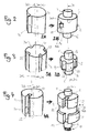
- the Figures 2 to 4 illustrate advantageous embodiments based on a drawn profile, and which ensure a good retention of the spring.
- the figure 2 illustrates the production of a barrel shaft 1 with hook 34, by a first drawing operation according to the Figure 2A , with a continuous profile 30 according to the Figure 1A , or 1B in a variant where the continuous profile 30 is that of a hook 34 conjugated to a housing 35 which allows a better recovery of the first inner turn 11 by the next turn.
- the profile of the hook 34 conjugated to this housing 35 corresponds to that of an eyelet 16 which has an inner end 12 of the first inner turn 11 of a spiral band spring barrel 10 of a certain type.
- the figure 3 illustrates the embodiment of a barrel shaft 1 having tangential grooves 33 parallel to the barrel shaft, by a first drawing operation according to the figure 3A , with a continuous profile 30 as illustrated for example in FIGS. igures 1F, 1J, 1K, 1L , and a resumption of machining operation according to the figure 3B , also preferably in machining to finish the shaft 1 and its upper surfaces 5 and lower 6.
- a shaft 1 in conjunction with a spring 10 arranged in a particular manner and without breaking point thanks to a corrugated profile without a folding zone or very small radius area, ensures a very good peripheral support of this spring 10 over the entire extent of his first turn 11.
- FIGS. 5C and 5D illustrate an advantageous variant of spring 10 stamped so as to create, between parallel slots according to the elongation of this spring, at least one folded median tab forming a projection protruding from the rest of the surface of the spring 10.
- This configuration brings the advantage of allowing the recovery of the frolic spring. It is usable, not only in this particular case where it is advantageous to cooperate at least one such boss 15 with grooves 33 of a shaft 1, but also in the general case where it is desired to position precisely, according to the direction of the barrel axis (or else of a balance shaft, or any axis intended to receive a spiral spring clock), such a spiral spring, and in particular, in the case of a barrel, by relative to the drum, and to the possible cover.
- the figure 4 illustrates the embodiment of a barrel shaft 1 having a tangential groove 32 parallel to the barrel shaft DB, crossing a circular groove 44 oriented on an axis parallel to the axis of the shaft and therefore eccentric to the axis of the barrel, by a first drawing operation in which is performed the tangential groove 32, according to the Figure 4A , with a continuous profile 30 according to the figure 1 G , and a resumption of machining operation according to the Figure 4B at which the circular groove 43 and its upper and lower boundary surfaces 44A and 44B are formed, and the upper and lower surfaces 6 of the shaft 1.
- the tangential groove 32 has a width LG greater than the defined width LI of the first internal turn 11.
- the Figures 9C and 9D show a preferred variant of associated spring 10, having an end 12 in tee, with a head 18 of length LT connected to the rest of the spring 10 by a core 19, preferably adjacent to the chamfers 19A for a better support in winding the spring.
- the width LG is greater than or equal to, and preferably equal to, this length LT of a transverse bar.
- the width LL of the circular groove 44 is equal to the width of the core 19, and the bottom of the groove 44 defines a cylindrical bearing surface 2A for the support of this core 19, the sector of support 2 serving for its part to support the section of the spring, in its total width LI, which follows the web 19, opposite the head 18.
- the Figure 17A illustrates a particular embodiment of the inner end of the dovetail spring, to cooperate with an opposing profile formed on the shaft, here having two shoulders.
- the Figure 17B illustrates a similar variant with a spring end 12 having two clearances cooperating in stop with two pins stuck in the corresponding shaft1; preferably, the end 12 of the spring 10 is embedded in a circular groove 44, resting on a groove flank 46 of at least one side, and preferably on both sides.
- the method of manufacturing such a shaft 1 advantageously comprises a machining operation means 7 for driving a ratchet, by threading or tapping or turning or milling facets, as visible on the figure 19 where these drive means 7 are constituted by a conventional square.
- these drive means 7 consist of a tapping or threading that can be made by turning during the second recovery operation of the shaft 1 after the drawing, as visible on the drawing.
- Figure 4A thread
- Figure 5B Female thread
- the Figures 8A and 8B represent a shaft 1 having a front groove 41 opening through an opening 42, and receiving the inner end 12 of the spring 11, made by a method which comprises a machining operation of a front groove 41 of revolution about an axis DG parallel or coincident with the pivot axis D, the front groove 41 being of width LH equal to a defined width LI of the first inner turn 11 of a spiral band spring barrel 10 of a determined type.
- machining operation further comprises machining at least one opening 42 in an outer wall 43 of the front groove 41, the opening 42 being of greater width than a defined thickness El of the first inner turn 11 of a spring barrel 10 in spiral band of a determined type, for the passage of this first inner turn 11.
- a surface roughness is imparted to at least a portion of the axis bearing sector 2.
- DC in the form of a groove made during the first drawing operation, or a knurling performed during the second machining operation.
- This roughness allows a maintenance by friction between the shaft and the spring, especially if the spring comprises, at the first inner coil 11, on its face facing the axis of the shaft 1, a similar friction surface.
- a friction surface may, as an alternative to this mechanical development, result from a surface treatment, a metallization type projection, or the like.
- the invention relates to a driving element 100 of a watch cylinder, comprising at least on the one hand a coil spring 10 of a certain type having a first internal turn 11 with a width L1 and a thickness E1 defined and the first inner turn 11 comprising, for its maintenance on a barrel shaft 1, at an inner end 12, fastening means 13 of profile 14 defined.
- This motor element 10 further comprises a barrel shaft 1 preferably derived from drawing a bar 50 and made by one of the methods described above.
- This shaft 1 comprises pivoting guide means 5, 6, around a pivot axis DP, and comprises at least one bearing sector 2 for the support of such a first inner turn 11 of at least one such a mainspring spring 10, the shaft 1 comprising complementary coupling means 3 of profile 314 complementary to the profile 14 of the attachment means 13 for its cooperation in pivoting with this at least one spring 10.
- the complementary fastening means 13 of the shaft 1 are respectively recessed or in salient relief.
- the shaft 1 comprises, internally recessed with respect to a cylinder, or with respect to a helical section prism and parallel to the axis of pivoting of the shaft 1, comprising the sector 2, at least one cavity 4 for receiving the attachment means 13 and / or at least a part of the first inner turn 11.
- this cavity 4 comprises a front groove 41 whose width LH is arranged for the minimum clearance clearance of the spring 10.
- the front groove 41 is of revolution about a parallel axis DG or coincides with the axis of pivoting D, and its width LH is equal to the defined width LI of the first inner turn 11 of a said mainspring spring 10.
- the shaft 1 has at least one opening 42 in an outer wall 43 of the front groove 41, this opening 42 having a width greater than the defined thickness E1 of the first internal turn 11, for the passage of the first inner turn 11.
- this opening 12 is wide enough to allow the first turn 11 to be held. without excessive stress, while being small enough to ensure a good maintenance of the end 12 of the spring 10.
- the central angle in which this opening is between 120 ° and 180 °.
- the shaft 1 comprises, internally recessed with respect to a cylinder, or with a sectional prism helix parallel to the axis of pivoting of the shaft 1, having the bearing sector 2, at least one cavity 4 for the reception of the attachment means 13 and / or at least a part of the first internal turn 11, and the at least one cavity 4 has a plurality of tangential grooves 33 parallel to the pivot axis D and each of profile corresponding to that of a boss 15 that includes the first inner coil 11 of a coil spring 10 spiral band of a specific type, the grooves 33 preferably being angularly equidistant around a cylinder, or around a section prism helically and parallel to the axis of pivoting of the shaft 1, having the bearing sector 2 DC axis.
- This equidistance is not essential, but it has the advantage of being able to present the spring 10 bearing, by its boss 15 closest to the free end 12, in any of the grooves 33, the other bosses 15 are then naturally in phase with the other grooves 33.
- the spring 10 then comprises a series of bosses 15 in number less than or equal to that of the grooves 33, spaced from the same curvilinear pitch as the grooves 33, and arranged to fit into the grooves 32.
- the shaft 1 comprises, internally recessed with respect to a cylinder, or with respect to a section prism helically and parallel to the axis of pivoting of the shaft 1, comprising the bearing sector 2, at least one cavity 4 for receiving the attachment means 13 and / or at least a part of the first internal turn 11.
- the DC axis of the support sector 2 is parallel or coincides with the pivot axis D, and at least one such cavity 4 is dimensioned for the clearance-free reception, in the direction of the width LI of the spring 10, the inner end 12 or at least a portion of the first inner turn 11.
- the shaft 1 comprises, internally recessed with respect to a cylinder, or with respect to a helical section prism and parallel to the axis of pivoting of the shaft 1, comprising the sector 2, at least one cavity 4 for receiving the attachment means 13 and / or at least a portion of the first inner turn 11, and the cavity 4 has a revolution groove 44 about the axis DC of the support sector 2 and width LR equal to the width LI of the first inner turn 11 of the spring 10.
- the shaft 1 comprises, internally recessed with respect to a cylinder, or with respect to a helical section prism and parallel to the axis of pivoting of the shaft 1, including the bearing sector 2, a slot narrow 38 of width LF much lower than the defined width LI of the first inner turn 11, and in which is inserted a pin 39 or a shim of foil constituting the complementary attachment means 3.
- FIG. 10A and 10B illustrate a shaft 1 having a cavity 4 formed by a recess radiated half-moon.
- the corresponding spring 10 has an inner end 12 wound in a small radius, and housed in this recess 4.
- the Figures 11A and 11B illustrate, a shaft 1 comprising, substantially parallel to each other, a plate 47 and a slot 48 for housing the inner coil 11 of the spring 10: its inner end 12 bears on the plate 47, and the turn 11 is slipped into slot 48.
- the thickness E 1 defined of the first internal turn 11 of the spring 10 is smaller than the thickness ES of the following turns of the spring 10, which subsequent turns are either constant section between them, or of progressive section away from the first inner turn 11.
- This embodiment is applicable to all the variants of barrel shafts described here, and it allows an optimal plating of the first inner turn 11 on the shaft 1, and in particular on the cylindrical sector (s) which 'it comprises.
- the free end 12 comprises a chamfer 121 or a radius, so as to allow a good winding of the next turn.
- At least the inner end 12 of the first inner turn 11 of the spring 10 comprises, on its inner face intended to bear on the bearing sector 2 of the shaft 1, a roughness greater than 12 micrometers Ra.
- the relative retention between the spring 10 and the shaft 1 can be provided by removable and complementary means, such as eyelet and hook, or the like. In an alternative, it can be ensured by a permanent connection between them, by a method of fixing, in particular irreversible, by welding, brazing, bonding, or the like.
- a motor element 100 at least one such spring 10 is welded to the shaft 1 at two points 51, 52 substantially diametrically opposite to the axis DC of the bearing sector 2.
- these points 51 and 52 are applied at the level of flats 36 and 37 of the shaft 1, substantially diametrically opposite with respect to the axis DC of the bearing sector 2.
- shafts 1 designed specifically for springs 10 of a given type allow the counter elements to be dimensioned so as to ensure a play-free assembly of the one on the other.
- at least one such spring 10 is held without play in an annular groove 44 of the shaft 1 around the bearing sector 2, or in a straight groove 45 of the shaft 1 along a generatrix of the shaft 1 .
- the inner end 12, or at least a part of the first turn 11, is irreversibly maintained in such a groove 44, 45, by welding or soldering, or else very economical way, by hammering or local crushing at the level of deformation zones 53, at the level of the spring 10 and / or at the level of the shaft 1.
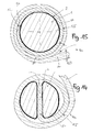
- the figures 16B and 16C illustrate a spring 10 mounted fitted and projecting in a circular groove 44 of a shaft 1, and hammered in position for its retention, in particular by the action of a wheel or the like, so as to create deformation surfaces 53 immobilizing the spring relative to the shaft.
- the figure 16D similarly illustrates, and preferred in the usual case where the hardness of the spring is greater than that of the shaft, an application where the wheel is applied to the walls of a groove in which the spring is gripped to imprison it under deformation zones 53.
- All the above-mentioned configurations are suitable for stopping the spring 10 on the shaft 1 by a welding point, laser welding (radial or parallel to the axis), brazing, bonding, or the like.
- the invention also relates to a timepiece mechanism 1000 comprising at least one such motor element 100.
- This mechanism 1000 is a cylinder 200, or a movement 300 incorporating at least one cylinder 200, or a timepiece 400 incorporating at least one movement 300 incorporating at least one cylinder 200.
Landscapes
- Physics & Mathematics (AREA)
- General Physics & Mathematics (AREA)
- Springs (AREA)
- Wire Processing (AREA)
- Metal Extraction Processes (AREA)
- Ropes Or Cables (AREA)
Priority Applications (7)
| Application Number | Priority Date | Filing Date | Title |
|---|---|---|---|
| EP12165537.7A EP2657794B1 (de) | 2012-04-25 | 2012-04-25 | Federwelle und Zugfeder |
| EP13163792.8A EP2674817B1 (de) | 2012-04-25 | 2013-04-15 | Verfahren zur Herstellung eines Uhrfederhauswelle |
| RU2013119128A RU2609397C2 (ru) | 2012-04-25 | 2013-04-24 | Вал барабана и ходовая пружина |
| US13/869,480 US9317013B2 (en) | 2012-04-25 | 2013-04-24 | Method of producing drive element for a timepiece barrel including a barrel arbor and mainspring |
| JP2013092016A JP5749760B2 (ja) | 2012-04-25 | 2013-04-25 | 香箱真及びゼンマイ |
| CN201310148320.7A CN103376727B (zh) | 2012-04-25 | 2013-04-25 | 条轴和主发条 |
| HK14103820.4A HK1190805B (en) | 2012-04-25 | 2014-04-22 | Barrel arbour and mainspring |
Applications Claiming Priority (1)
| Application Number | Priority Date | Filing Date | Title |
|---|---|---|---|
| EP12165537.7A EP2657794B1 (de) | 2012-04-25 | 2012-04-25 | Federwelle und Zugfeder |
Publications (2)
| Publication Number | Publication Date |
|---|---|
| EP2657794A1 true EP2657794A1 (de) | 2013-10-30 |
| EP2657794B1 EP2657794B1 (de) | 2017-02-01 |
Family
ID=48050616
Family Applications (2)
| Application Number | Title | Priority Date | Filing Date |
|---|---|---|---|
| EP12165537.7A Active EP2657794B1 (de) | 2012-04-25 | 2012-04-25 | Federwelle und Zugfeder |
| EP13163792.8A Active EP2674817B1 (de) | 2012-04-25 | 2013-04-15 | Verfahren zur Herstellung eines Uhrfederhauswelle |
Family Applications After (1)
| Application Number | Title | Priority Date | Filing Date |
|---|---|---|---|
| EP13163792.8A Active EP2674817B1 (de) | 2012-04-25 | 2013-04-15 | Verfahren zur Herstellung eines Uhrfederhauswelle |
Country Status (5)
| Country | Link |
|---|---|
| US (1) | US9317013B2 (de) |
| EP (2) | EP2657794B1 (de) |
| JP (1) | JP5749760B2 (de) |
| CN (1) | CN103376727B (de) |
| RU (1) | RU2609397C2 (de) |
Cited By (2)
| Publication number | Priority date | Publication date | Assignee | Title |
|---|---|---|---|---|
| EP2977827A1 (de) * | 2014-07-22 | 2016-01-27 | Montres Breguet SA | Federgehäuse einer Uhr mit verbesserter Kraftübertragung |
| EP3872576A1 (de) * | 2020-02-25 | 2021-09-01 | ETA SA Manufacture Horlogère Suisse | Federgehäuse eines uhrwerks mit verdrehter welle |
Families Citing this family (16)
| Publication number | Priority date | Publication date | Assignee | Title |
|---|---|---|---|---|
| CN104412175B (zh) * | 2012-06-28 | 2017-05-17 | 尼瓦洛克斯-法尔股份有限公司 | 钟表的主发条 |
| EP3106935A1 (de) * | 2015-06-16 | 2016-12-21 | Nivarox-FAR S.A. | Herstellungsverfahren eines werstücks, das einen modifizierten polierschritt umfasst |
| EP3106928A1 (de) * | 2015-06-16 | 2016-12-21 | Nivarox-FAR S.A. | Herstellungsverfahren, das einen modifizierten automatendreh-schritt umfasst |
| WO2017005394A1 (fr) * | 2015-07-07 | 2017-01-12 | Patek Philippe Sa Geneve | Arbre de barillet d'horlogerie |
| EP3118692B1 (de) * | 2015-07-16 | 2018-12-26 | Nivarox-FAR S.A. | Befestigung der spiralfeder eines uhrwerks durch verklebung |
| EP3176650B1 (de) * | 2015-12-02 | 2019-02-06 | Nivarox-FAR S.A. | Schutz einer uhrkomponente aus mikro-bearbeitbarem material |
| JP6753127B2 (ja) * | 2016-04-25 | 2020-09-09 | セイコーエプソン株式会社 | 時計用ムーブメントおよび時計 |
| EP3255510B1 (de) * | 2016-06-10 | 2019-06-05 | Nivarox-FAR S.A. | Kalander und kalandrierverfahren einer schliesszylinderfeder einer uhr |
| JP7133909B2 (ja) * | 2016-07-04 | 2022-09-09 | ロレックス・ソシエテ・アノニム | 時計用組立体の製造方法、及び該製造方法により得られる時計用組立体 |
| JP2018054562A (ja) * | 2016-09-30 | 2018-04-05 | セイコーエプソン株式会社 | 時計用動力装置および時計用動力装置の製造方法 |
| CH713389B1 (fr) * | 2017-01-27 | 2020-11-30 | Richemont Int Sa | Système de liaison d'un arbre à une pièce. |
| EP3499316B1 (de) * | 2017-12-15 | 2024-08-07 | Nivarox-FAR S.A. | Schliesszylinderfeder für ein uhrwerk einer uhr, und herstellungsverfahren einer solchen feder |
| CH716092B1 (fr) | 2018-04-26 | 2022-10-31 | Patek Philippe Sa Geneve | Barillet d'horlogerie et procédé de modification de mouvement horloger. |
| US11877904B2 (en) | 2018-05-31 | 2024-01-23 | Koninklijke Philips N.V. | Drivetrain assembly for a personal care device |
| JP7160389B2 (ja) * | 2021-02-19 | 2022-10-25 | 速水発条株式会社 | 渦巻きばね装置 |
| EP4733854A1 (de) * | 2024-10-22 | 2026-04-29 | Nivarox-FAR S.A. | Verfahren zur herstellung einer zylinderwelle |
Citations (4)
| Publication number | Priority date | Publication date | Assignee | Title |
|---|---|---|---|---|
| US820252A (en) * | 1905-06-19 | 1906-05-08 | New Haven Clock Co | Watch-barrel arbor. |
| CH117808A (de) * | 1925-01-29 | 1926-12-01 | Sicherung für Federtriebwerke. | |
| US3846974A (en) * | 1972-12-18 | 1974-11-12 | Ebauchesfabrik Eta Ag | Motor-barrel watch movement |
| FR2329000A1 (fr) * | 1975-10-21 | 1977-05-20 | Ebauchesfabrik Eta Ag | Arbre de barillet extractible pour mouvement de montre |
Family Cites Families (10)
| Publication number | Priority date | Publication date | Assignee | Title |
|---|---|---|---|---|
| DE471680C (de) * | 1929-02-15 | Feinbau Maschinen Akt Ges | Federachse | |
| DE1176574B (de) * | 1953-10-27 | 1964-08-20 | Dr Reinhard Straumann | Federhaus mit Rutschkupplung fuer Selbst-aufzuguhren |
| CH672973A4 (de) * | 1973-05-11 | 1976-05-14 | ||
| JPH0648152Y2 (ja) * | 1988-10-20 | 1994-12-07 | 株式会社精工舎 | ゼンマイ動力機構 |
| JPH02140490U (de) * | 1989-04-27 | 1990-11-26 | ||
| CN100451874C (zh) * | 2003-03-11 | 2009-01-14 | 弗兰克.米勒.瓦差兰股份有限公司 | 计时仪器的盘簧 |
| ATE430953T1 (de) * | 2004-07-02 | 2009-05-15 | Nivarox Sa | Spiralfeder aus zwei materialen mit selbstkompensation |
| JP5050756B2 (ja) * | 2007-09-28 | 2012-10-17 | セイコーエプソン株式会社 | ゼンマイ装置および時計 |
| CN201662690U (zh) * | 2010-03-30 | 2010-12-01 | 天津海鸥表业集团有限公司 | 一种大型机械表机芯的条轴结构 |
| EP2420899B1 (de) * | 2010-08-19 | 2018-12-19 | ETA SA Manufacture Horlogère Suisse | Federhaus für Uhren mit automatischer Aufziehfunktion |
-
2012
- 2012-04-25 EP EP12165537.7A patent/EP2657794B1/de active Active
-
2013
- 2013-04-15 EP EP13163792.8A patent/EP2674817B1/de active Active
- 2013-04-24 RU RU2013119128A patent/RU2609397C2/ru active
- 2013-04-24 US US13/869,480 patent/US9317013B2/en active Active
- 2013-04-25 JP JP2013092016A patent/JP5749760B2/ja active Active
- 2013-04-25 CN CN201310148320.7A patent/CN103376727B/zh active Active
Patent Citations (4)
| Publication number | Priority date | Publication date | Assignee | Title |
|---|---|---|---|---|
| US820252A (en) * | 1905-06-19 | 1906-05-08 | New Haven Clock Co | Watch-barrel arbor. |
| CH117808A (de) * | 1925-01-29 | 1926-12-01 | Sicherung für Federtriebwerke. | |
| US3846974A (en) * | 1972-12-18 | 1974-11-12 | Ebauchesfabrik Eta Ag | Motor-barrel watch movement |
| FR2329000A1 (fr) * | 1975-10-21 | 1977-05-20 | Ebauchesfabrik Eta Ag | Arbre de barillet extractible pour mouvement de montre |
Cited By (4)
| Publication number | Priority date | Publication date | Assignee | Title |
|---|---|---|---|---|
| EP2977827A1 (de) * | 2014-07-22 | 2016-01-27 | Montres Breguet SA | Federgehäuse einer Uhr mit verbesserter Kraftübertragung |
| US9513601B2 (en) | 2014-07-22 | 2016-12-06 | Montres Breguet S.A. | Timepiece barrel with improved transmission of force |
| EP3872576A1 (de) * | 2020-02-25 | 2021-09-01 | ETA SA Manufacture Horlogère Suisse | Federgehäuse eines uhrwerks mit verdrehter welle |
| US11782386B2 (en) | 2020-02-25 | 2023-10-10 | Eta Sa Manufacture Horlogère Suisse | Timepiece barrel with a twisted arbour |
Also Published As
| Publication number | Publication date |
|---|---|
| HK1190805A1 (zh) | 2014-07-11 |
| EP2674817B1 (de) | 2020-05-27 |
| CN103376727A (zh) | 2013-10-30 |
| EP2674817A2 (de) | 2013-12-18 |
| RU2609397C2 (ru) | 2017-02-01 |
| RU2013119128A (ru) | 2014-10-27 |
| US9317013B2 (en) | 2016-04-19 |
| EP2674817A3 (de) | 2017-05-17 |
| EP2657794B1 (de) | 2017-02-01 |
| US20130283615A1 (en) | 2013-10-31 |
| JP2013228393A (ja) | 2013-11-07 |
| CN103376727B (zh) | 2016-02-10 |
| JP5749760B2 (ja) | 2015-07-15 |
Similar Documents
| Publication | Publication Date | Title |
|---|---|---|
| EP2657794A1 (de) | Federwelle und Zugfeder | |
| EP2437125B1 (de) | Uhr | |
| EP2756360B1 (de) | Federgehäuse für eine uhr mit kleinem kerndurchmesser | |
| EP2634649B1 (de) | Ökonomisches Federgehäuse für Uhrwerk | |
| EP3889689B1 (de) | Antriebsorgan für uhr | |
| EP2834712B1 (de) | Federhaus, das eine zugfeder und eine federhauswelle umfasst | |
| EP2756358B1 (de) | Uhren-federgehäuse mit reduziertem kernesdurchmesser | |
| EP2756359B1 (de) | Uhren-federgehäuse mit reduziertem durchmesser des bundes | |
| CH706432A2 (fr) | Procédé de fabrication d'un arbre de barillet d'horlogerie, élément moteur de barillet et mécanisme d'horlogerie. | |
| EP2570863B1 (de) | Uhren-Federgehäuse mit reduziertem Durchmesser des Bundes | |
| EP3252541B1 (de) | Teil zum befestigen einer unruhspiralfeder | |
| EP4194966B1 (de) | Verriegelung zur begrenzung der axialen auslenkung eines beweglichen teils eines uhrwerks und uhrwerk mit einem solchen riegel | |
| EP3293585B1 (de) | Spiralklötzchenträger und regulierungsverfahren der position eines spiralklötzchens in einem solchen spiralklötzchenträger | |
| FR2951790A1 (fr) | Rondelle d'arret axial d'un pignon sur un arbre, notamment sur un arbre de boite de vitesses | |
| CH706901A2 (fr) | Arbre de barillet d'horlogerie. | |
| CH709807B1 (fr) | Mécanisme d'indication apte à transformer deux rotations successives dans un même sens en une rotation alternative, notamment pour pièce d'horlogerie. | |
| EP3250842B1 (de) | Torsionsdämpfer mit gerade schraubenfeder | |
| EP2703908A1 (de) | Federwelle für Uhrwerk | |
| EP4474543A1 (de) | Ausgangshebel mit nachlaufrollen eines exzenterantriebs und verfahren zu seiner herstellung | |
| FR2793863A1 (fr) | Element de came et de portee pour des arbres a came legers assembles | |
| WO2015049165A1 (fr) | Ressort moteur pour barillet moteur minimisant l'usure du tambour | |
| EP4107585A1 (de) | Oszillierende aufziehmasse, die mit einem dreh-dekorelement für ein automatisches uhrwerk versehen ist | |
| EP3974913A1 (de) | Federgehäuse für uhr | |
| HK1190805B (en) | Barrel arbour and mainspring |
Legal Events
| Date | Code | Title | Description |
|---|---|---|---|
| PUAI | Public reference made under article 153(3) epc to a published international application that has entered the european phase |
Free format text: ORIGINAL CODE: 0009012 |
|
| AK | Designated contracting states |
Kind code of ref document: A1 Designated state(s): AL AT BE BG CH CY CZ DE DK EE ES FI FR GB GR HR HU IE IS IT LI LT LU LV MC MK MT NL NO PL PT RO RS SE SI SK SM TR |
|
| AX | Request for extension of the european patent |
Extension state: BA ME |
|
| 17P | Request for examination filed |
Effective date: 20140430 |
|
| RBV | Designated contracting states (corrected) |
Designated state(s): AL AT BE BG CH CY CZ DE DK EE ES FI FR GB GR HR HU IE IS IT LI LT LU LV MC MK MT NL NO PL PT RO RS SE SI SK SM TR |
|
| 17Q | First examination report despatched |
Effective date: 20140616 |
|
| GRAP | Despatch of communication of intention to grant a patent |
Free format text: ORIGINAL CODE: EPIDOSNIGR1 |
|
| INTG | Intention to grant announced |
Effective date: 20161110 |
|
| GRAS | Grant fee paid |
Free format text: ORIGINAL CODE: EPIDOSNIGR3 |
|
| GRAA | (expected) grant |
Free format text: ORIGINAL CODE: 0009210 |
|
| AK | Designated contracting states |
Kind code of ref document: B1 Designated state(s): AL AT BE BG CH CY CZ DE DK EE ES FI FR GB GR HR HU IE IS IT LI LT LU LV MC MK MT NL NO PL PT RO RS SE SI SK SM TR |
|
| REG | Reference to a national code |
Ref country code: GB Ref legal event code: FG4D Free format text: NOT ENGLISH |
|
| REG | Reference to a national code |
Ref country code: CH Ref legal event code: EP Ref country code: CH Ref legal event code: NV Representative=s name: ICB INGENIEURS CONSEILS EN BREVETS SA, CH Ref country code: AT Ref legal event code: REF Ref document number: 866065 Country of ref document: AT Kind code of ref document: T Effective date: 20170215 |
|
| REG | Reference to a national code |
Ref country code: IE Ref legal event code: FG4D Free format text: LANGUAGE OF EP DOCUMENT: FRENCH |
|
| REG | Reference to a national code |
Ref country code: DE Ref legal event code: R096 Ref document number: 602012028156 Country of ref document: DE |
|
| REG | Reference to a national code |
Ref country code: FR Ref legal event code: PLFP Year of fee payment: 6 |
|
| REG | Reference to a national code |
Ref country code: NL Ref legal event code: MP Effective date: 20170201 |
|
| REG | Reference to a national code |
Ref country code: LT Ref legal event code: MG4D |
|
| REG | Reference to a national code |
Ref country code: AT Ref legal event code: MK05 Ref document number: 866065 Country of ref document: AT Kind code of ref document: T Effective date: 20170201 |
|
| PG25 | Lapsed in a contracting state [announced via postgrant information from national office to epo] |
Ref country code: FI Free format text: LAPSE BECAUSE OF FAILURE TO SUBMIT A TRANSLATION OF THE DESCRIPTION OR TO PAY THE FEE WITHIN THE PRESCRIBED TIME-LIMIT Effective date: 20170201 Ref country code: LT Free format text: LAPSE BECAUSE OF FAILURE TO SUBMIT A TRANSLATION OF THE DESCRIPTION OR TO PAY THE FEE WITHIN THE PRESCRIBED TIME-LIMIT Effective date: 20170201 Ref country code: GR Free format text: LAPSE BECAUSE OF FAILURE TO SUBMIT A TRANSLATION OF THE DESCRIPTION OR TO PAY THE FEE WITHIN THE PRESCRIBED TIME-LIMIT Effective date: 20170502 Ref country code: IS Free format text: LAPSE BECAUSE OF FAILURE TO SUBMIT A TRANSLATION OF THE DESCRIPTION OR TO PAY THE FEE WITHIN THE PRESCRIBED TIME-LIMIT Effective date: 20170601 Ref country code: HR Free format text: LAPSE BECAUSE OF FAILURE TO SUBMIT A TRANSLATION OF THE DESCRIPTION OR TO PAY THE FEE WITHIN THE PRESCRIBED TIME-LIMIT Effective date: 20170201 Ref country code: NO Free format text: LAPSE BECAUSE OF FAILURE TO SUBMIT A TRANSLATION OF THE DESCRIPTION OR TO PAY THE FEE WITHIN THE PRESCRIBED TIME-LIMIT Effective date: 20170501 |
|
| PG25 | Lapsed in a contracting state [announced via postgrant information from national office to epo] |
Ref country code: PT Free format text: LAPSE BECAUSE OF FAILURE TO SUBMIT A TRANSLATION OF THE DESCRIPTION OR TO PAY THE FEE WITHIN THE PRESCRIBED TIME-LIMIT Effective date: 20170601 Ref country code: ES Free format text: LAPSE BECAUSE OF FAILURE TO SUBMIT A TRANSLATION OF THE DESCRIPTION OR TO PAY THE FEE WITHIN THE PRESCRIBED TIME-LIMIT Effective date: 20170201 Ref country code: PL Free format text: LAPSE BECAUSE OF FAILURE TO SUBMIT A TRANSLATION OF THE DESCRIPTION OR TO PAY THE FEE WITHIN THE PRESCRIBED TIME-LIMIT Effective date: 20170201 Ref country code: SE Free format text: LAPSE BECAUSE OF FAILURE TO SUBMIT A TRANSLATION OF THE DESCRIPTION OR TO PAY THE FEE WITHIN THE PRESCRIBED TIME-LIMIT Effective date: 20170201 Ref country code: RS Free format text: LAPSE BECAUSE OF FAILURE TO SUBMIT A TRANSLATION OF THE DESCRIPTION OR TO PAY THE FEE WITHIN THE PRESCRIBED TIME-LIMIT Effective date: 20170201 Ref country code: AT Free format text: LAPSE BECAUSE OF FAILURE TO SUBMIT A TRANSLATION OF THE DESCRIPTION OR TO PAY THE FEE WITHIN THE PRESCRIBED TIME-LIMIT Effective date: 20170201 Ref country code: BG Free format text: LAPSE BECAUSE OF FAILURE TO SUBMIT A TRANSLATION OF THE DESCRIPTION OR TO PAY THE FEE WITHIN THE PRESCRIBED TIME-LIMIT Effective date: 20170501 Ref country code: LV Free format text: LAPSE BECAUSE OF FAILURE TO SUBMIT A TRANSLATION OF THE DESCRIPTION OR TO PAY THE FEE WITHIN THE PRESCRIBED TIME-LIMIT Effective date: 20170201 Ref country code: NL Free format text: LAPSE BECAUSE OF FAILURE TO SUBMIT A TRANSLATION OF THE DESCRIPTION OR TO PAY THE FEE WITHIN THE PRESCRIBED TIME-LIMIT Effective date: 20170201 |
|
| PG25 | Lapsed in a contracting state [announced via postgrant information from national office to epo] |
Ref country code: SK Free format text: LAPSE BECAUSE OF FAILURE TO SUBMIT A TRANSLATION OF THE DESCRIPTION OR TO PAY THE FEE WITHIN THE PRESCRIBED TIME-LIMIT Effective date: 20170201 Ref country code: IT Free format text: LAPSE BECAUSE OF FAILURE TO SUBMIT A TRANSLATION OF THE DESCRIPTION OR TO PAY THE FEE WITHIN THE PRESCRIBED TIME-LIMIT Effective date: 20170201 Ref country code: EE Free format text: LAPSE BECAUSE OF FAILURE TO SUBMIT A TRANSLATION OF THE DESCRIPTION OR TO PAY THE FEE WITHIN THE PRESCRIBED TIME-LIMIT Effective date: 20170201 Ref country code: CZ Free format text: LAPSE BECAUSE OF FAILURE TO SUBMIT A TRANSLATION OF THE DESCRIPTION OR TO PAY THE FEE WITHIN THE PRESCRIBED TIME-LIMIT Effective date: 20170201 Ref country code: RO Free format text: LAPSE BECAUSE OF FAILURE TO SUBMIT A TRANSLATION OF THE DESCRIPTION OR TO PAY THE FEE WITHIN THE PRESCRIBED TIME-LIMIT Effective date: 20170201 |
|
| REG | Reference to a national code |
Ref country code: DE Ref legal event code: R097 Ref document number: 602012028156 Country of ref document: DE |
|
| PG25 | Lapsed in a contracting state [announced via postgrant information from national office to epo] |
Ref country code: SM Free format text: LAPSE BECAUSE OF FAILURE TO SUBMIT A TRANSLATION OF THE DESCRIPTION OR TO PAY THE FEE WITHIN THE PRESCRIBED TIME-LIMIT Effective date: 20170201 Ref country code: DK Free format text: LAPSE BECAUSE OF FAILURE TO SUBMIT A TRANSLATION OF THE DESCRIPTION OR TO PAY THE FEE WITHIN THE PRESCRIBED TIME-LIMIT Effective date: 20170201 |
|
| PLBE | No opposition filed within time limit |
Free format text: ORIGINAL CODE: 0009261 |
|
| STAA | Information on the status of an ep patent application or granted ep patent |
Free format text: STATUS: NO OPPOSITION FILED WITHIN TIME LIMIT |
|
| 26N | No opposition filed |
Effective date: 20171103 |
|
| GBPC | Gb: european patent ceased through non-payment of renewal fee |
Effective date: 20170501 |
|
| REG | Reference to a national code |
Ref country code: IE Ref legal event code: MM4A |
|
| PG25 | Lapsed in a contracting state [announced via postgrant information from national office to epo] |
Ref country code: MC Free format text: LAPSE BECAUSE OF FAILURE TO SUBMIT A TRANSLATION OF THE DESCRIPTION OR TO PAY THE FEE WITHIN THE PRESCRIBED TIME-LIMIT Effective date: 20170201 |
|
| PG25 | Lapsed in a contracting state [announced via postgrant information from national office to epo] |
Ref country code: LU Free format text: LAPSE BECAUSE OF NON-PAYMENT OF DUE FEES Effective date: 20170425 Ref country code: SI Free format text: LAPSE BECAUSE OF FAILURE TO SUBMIT A TRANSLATION OF THE DESCRIPTION OR TO PAY THE FEE WITHIN THE PRESCRIBED TIME-LIMIT Effective date: 20170201 |
|
| REG | Reference to a national code |
Ref country code: BE Ref legal event code: MM Effective date: 20170430 |
|
| REG | Reference to a national code |
Ref country code: FR Ref legal event code: PLFP Year of fee payment: 7 |
|
| PG25 | Lapsed in a contracting state [announced via postgrant information from national office to epo] |
Ref country code: GB Free format text: LAPSE BECAUSE OF NON-PAYMENT OF DUE FEES Effective date: 20170501 Ref country code: IE Free format text: LAPSE BECAUSE OF NON-PAYMENT OF DUE FEES Effective date: 20170425 |
|
| PG25 | Lapsed in a contracting state [announced via postgrant information from national office to epo] |
Ref country code: BE Free format text: LAPSE BECAUSE OF NON-PAYMENT OF DUE FEES Effective date: 20170430 |
|
| PG25 | Lapsed in a contracting state [announced via postgrant information from national office to epo] |
Ref country code: MT Free format text: LAPSE BECAUSE OF FAILURE TO SUBMIT A TRANSLATION OF THE DESCRIPTION OR TO PAY THE FEE WITHIN THE PRESCRIBED TIME-LIMIT Effective date: 20170201 |
|
| PG25 | Lapsed in a contracting state [announced via postgrant information from national office to epo] |
Ref country code: HU Free format text: LAPSE BECAUSE OF FAILURE TO SUBMIT A TRANSLATION OF THE DESCRIPTION OR TO PAY THE FEE WITHIN THE PRESCRIBED TIME-LIMIT; INVALID AB INITIO Effective date: 20120425 |
|
| PG25 | Lapsed in a contracting state [announced via postgrant information from national office to epo] |
Ref country code: CY Free format text: LAPSE BECAUSE OF NON-PAYMENT OF DUE FEES Effective date: 20170201 |
|
| PG25 | Lapsed in a contracting state [announced via postgrant information from national office to epo] |
Ref country code: MK Free format text: LAPSE BECAUSE OF FAILURE TO SUBMIT A TRANSLATION OF THE DESCRIPTION OR TO PAY THE FEE WITHIN THE PRESCRIBED TIME-LIMIT Effective date: 20170201 |
|
| PG25 | Lapsed in a contracting state [announced via postgrant information from national office to epo] |
Ref country code: TR Free format text: LAPSE BECAUSE OF FAILURE TO SUBMIT A TRANSLATION OF THE DESCRIPTION OR TO PAY THE FEE WITHIN THE PRESCRIBED TIME-LIMIT Effective date: 20170201 |
|
| PG25 | Lapsed in a contracting state [announced via postgrant information from national office to epo] |
Ref country code: AL Free format text: LAPSE BECAUSE OF FAILURE TO SUBMIT A TRANSLATION OF THE DESCRIPTION OR TO PAY THE FEE WITHIN THE PRESCRIBED TIME-LIMIT Effective date: 20170201 |
|
| P01 | Opt-out of the competence of the unified patent court (upc) registered |
Effective date: 20230701 |
|
| PGFP | Annual fee paid to national office [announced via postgrant information from national office to epo] |
Ref country code: DE Payment date: 20250319 Year of fee payment: 14 |
|
| PGFP | Annual fee paid to national office [announced via postgrant information from national office to epo] |
Ref country code: CH Payment date: 20250501 Year of fee payment: 14 |
|
| PGFP | Annual fee paid to national office [announced via postgrant information from national office to epo] |
Ref country code: FR Payment date: 20260319 Year of fee payment: 15 |