EP3889689B1 - Antriebsorgan für uhr - Google Patents
Antriebsorgan für uhr Download PDFInfo
- Publication number
- EP3889689B1 EP3889689B1 EP21168544.1A EP21168544A EP3889689B1 EP 3889689 B1 EP3889689 B1 EP 3889689B1 EP 21168544 A EP21168544 A EP 21168544A EP 3889689 B1 EP3889689 B1 EP 3889689B1
- Authority
- EP
- European Patent Office
- Prior art keywords
- drum
- timepiece
- fixed element
- mainspring
- variant
- Prior art date
- Legal status (The legal status is an assumption and is not a legal conclusion. Google has not performed a legal analysis and makes no representation as to the accuracy of the status listed.)
- Active
Links
Images




Classifications
-
- G—PHYSICS
- G04—HOROLOGY
- G04B—MECHANICALLY-DRIVEN CLOCKS OR WATCHES; MECHANICAL PARTS OF CLOCKS OR WATCHES IN GENERAL; TIME PIECES USING THE POSITION OF THE SUN, MOON OR STARS
- G04B1/00—Driving mechanisms
- G04B1/10—Driving mechanisms with mainspring
- G04B1/16—Barrels; Arbors; Barrel axles
-
- G—PHYSICS
- G04—HOROLOGY
- G04B—MECHANICALLY-DRIVEN CLOCKS OR WATCHES; MECHANICAL PARTS OF CLOCKS OR WATCHES IN GENERAL; TIME PIECES USING THE POSITION OF THE SUN, MOON OR STARS
- G04B1/00—Driving mechanisms
- G04B1/10—Driving mechanisms with mainspring
- G04B1/14—Mainsprings; Bridles therefor
-
- G—PHYSICS
- G04—HOROLOGY
- G04B—MECHANICALLY-DRIVEN CLOCKS OR WATCHES; MECHANICAL PARTS OF CLOCKS OR WATCHES IN GENERAL; TIME PIECES USING THE POSITION OF THE SUN, MOON OR STARS
- G04B1/00—Driving mechanisms
- G04B1/10—Driving mechanisms with mainspring
- G04B1/18—Constructions for connecting the ends of the mainsprings with the barrel or the arbor
-
- G—PHYSICS
- G04—HOROLOGY
- G04B—MECHANICALLY-DRIVEN CLOCKS OR WATCHES; MECHANICAL PARTS OF CLOCKS OR WATCHES IN GENERAL; TIME PIECES USING THE POSITION OF THE SUN, MOON OR STARS
- G04B33/00—Calibers
- G04B33/06—Calibers of extremely flat shape
-
- G—PHYSICS
- G04—HOROLOGY
- G04B—MECHANICALLY-DRIVEN CLOCKS OR WATCHES; MECHANICAL PARTS OF CLOCKS OR WATCHES IN GENERAL; TIME PIECES USING THE POSITION OF THE SUN, MOON OR STARS
- G04B33/00—Calibers
- G04B33/14—Calibers of which the mainsprings or barrels are easily removable
-
- G—PHYSICS
- G04—HOROLOGY
- G04B—MECHANICALLY-DRIVEN CLOCKS OR WATCHES; MECHANICAL PARTS OF CLOCKS OR WATCHES IN GENERAL; TIME PIECES USING THE POSITION OF THE SUN, MOON OR STARS
- G04B29/00—Frameworks
- G04B29/02—Plates; Bridges; Cocks
- G04B29/022—Bridges
Definitions
- the present invention relates to the field of watchmaking. It concerns, more particularly, a watch movement comprising a compact driving member.
- a barrel comprises a hollow drum comprising a cylindrical wall closed on one side by a bottom made in one piece with it, and on the other side by a cover, in order to form a housing for a spiral spring.
- the outer end of the spiral spring is connected by a fixed or sliding flange to the cylindrical wall of the drum, and the inner end of the spring is connected to a bung associated with a barrel arbor.
- the outer wall of the drum is typically provided with teeth in order to drive a going train, and the arbor is secured to a ratchet wheel, which is used for winding the spring. It is also known to drive the going train via the arbor and to wind the spring via the drum.
- smooth drums, without teeth are known, which drive the finishing gear by means of a chain and a spindle system.
- the above-mentioned conventional barrel is mounted on the frame by its center, namely directly or indirectly via the shaft.
- This arrangement is relatively bulky, and requires a certain height between the frame elements located on either side of the barrel in order to ensure that the barrel does not come into contact with neighboring components.
- the patent CH26510 omits the drum cover, the housing for the spring being delimited on one side by the bottom of the drum, and on the other side by a frame element of the movement, in particular the plate.
- the driving organ of this document proposes a drum also closed on one side by a frame element, in which the shaft has come from a piece with a wheel which is located entirely in the thickness of this frame element, in a recess provided in the latter.
- the drums of all the above-mentioned embodiments are supported by their center, which requires that the drum have a bottom integral with its side wall.
- the document CH 334702 reveals several variants of barrels in which the drum consists of a ring guided on its peripheral wall by means of three pairs of rollers distributed around the periphery of the drum. This drum has neither cover nor bottom, and the housing for the mainspring is defined on its lower and upper faces by bridges of the movement frame.
- the document FR 2229087 discloses a drive member in which the drum is supported radially by a recess in the bottom of the housing, this bottom serving as a frame element.
- the drum is open on both sides, and the housing thus defined for housing the spring is closed on the one hand by the bottom and on the other hand by the gear wheel.
- This arrangement is even simpler and more compact than those mentioned above, but the gear wheel is supported on both sides. The compactness of the drive member as well as its simplicity can therefore be further improved.
- An aim of the invention is therefore to propose a watch movement comprising a driving member in which the aforementioned defects are at least partially overcome.
- the invention relates to a watch movement for a timepiece, comprising a driving member which comprises a mainspring such as a spiral spring, and a drum delimiting an outer wall of a housing housing said mainspring.
- the outer end of the mainspring is connected to the drum, which is arranged to pivot about an axis of rotation.
- the drum has the shape of a toothed annular crown.
- the drive member further comprises a toothed wheel, which can for example serve as a ratchet wheel, secured to a plug to which an inner end of said drive spring is connected.
- One face of said housing is intended to be defined by a fixed element of said timepiece against which said drum is intended to be mounted, such as a frame element, a back, or a glass.
- said bung and said gear wheel are made in one piece.
- This construction results in a significant reduction in space requirement compared to the barrels of the prior art.
- the separate bung is thus made superfluous, which reduces the number of parts.
- said drum is supported by a ball bearing.
- the friction suffered by the drum during its rotations can therefore be minimized, while maintaining the thickness of the drive member to a minimum.
- the ball bearing can be bidirectional, or unidirectional. This latter possibility allows the drum to function as a ratchet, without requiring any pawl, in the case where the drive member is wound up by the drum.
- said ball bearing comprises a first groove located on the outer wall of said drum and a second groove facing said first groove, said second groove being located on the inner wall of an outer ring arranged to be fixed to said fixed element, the grooves thus defining an annular cavity.
- a plurality of balls are housed in this annular cavity. A compact construction is thus provided.
- said drum and said motor spring can come in one piece, which reduces the number of parts of the motor member and facilitates its assembly.
- said watch movement comprises said fixed element.
- said toothed wheel may be pivotally mounted on a fixed shaft extending from the fixed element or the barrel bridge.
- said fixed element may be a frame element of a watch movement of said timepiece such as a plate or a bridge, or a glass included in a timepiece on the back or dial side, or a back included in said timepiece.
- said barrel bridge may be integrated into a frame element or a back that said timepiece comprises.
- FIGS. 1 to 7 represent a first variant of a drive member 1 not forming the subject of the invention, which has been provided as an example.
- the drive member 1 is mounted on a fixed element 3 of a timepiece in which the drive member is implemented.
- This fixed element 3 can be a plate or a bridge, or a base on which the driving member 1 is directly or indirectly mounted.
- the driving member comprises a drum 5 having peripheral teeth 6.
- This drum 5 is devoid of a cover and a bottom, and defines a cylindrical housing in which a driving spring 7 is arranged.
- the latter is of conventional spiral shape, and is connected at its outer end to the inner wall of the drum 5, and at its inner end to a bung 9.
- the latter comes in one piece with a toothed wheel 11 which serves as a ratchet wheel in the illustrated embodiment, but which can also be used for driving the gears, the drum 5 serving as a ratchet in such a case.
- the gear wheel 11 extends superimposed on the spring 7, and serves as a barrel cover, but the plug may be made of a separate piece secured to the gear wheel 11.
- the plug 9 is pivoted about a fixed shaft 13, and is held on the latter by means of a screw 15 or similar which bears against the fixed shaft 13.
- the plug 9 comprises a hook 9a for connection with the inner end of the mainspring 7 formed directly in the plug 9, for example by means of wire EDM or sinking. Alternatively, it can be made by traditional broaching or milling.
- the gear wheel 11 acts as a cover for the barrel, which is not rotationally fixed to the drum 5, as known for example in the document CH 28684 .
- the drum 5 as such is devoid of a bottom and a cover, and is only a simple toothed ring.
- the drum 5 is positioned axially and radially by guide elements 17 distributed around the periphery of the drum 5.
- these guide elements 17 are, in the variant shown, studs, made here in the form of stones, driven into a barrel bridge 19, and which abut against a shoulder 21 provided on the drum 5.
- An advantage of using stones, such as rubies, for the studs is the low coefficient of friction of this material, but other materials are possible.
- the studs 17 can be made of hard metal, polymer or ceramic, and, in the case of metal, can be made of the same material as the barrel bridge 19.
- the studs can be replaced by a continuous or discontinuous surface of the barrel bridge 19, or by ball bearings.
- the studs 17 extend from the barrel bridge 19 in a direction parallel to the axis of rotation of the drum 5, and do not extend radially beyond the peripheral teeth 6 of the drum 5. Indeed, the guide elements 17 are inscribed in the diameter of the drum 5, which reduces the bulk in the plane of the drum 5 relative to the document CH 334702 above-mentioned.
- the drum 5 can simply abut against the surface of the fixed element 3 and slide on the latter during its pivoting movements.
- the drum 5 comprises guide stones 23 driven into corresponding housings and extending towards the fixed part 3. These guide stones reduce the contact surface between the drum 5 and the fixed part 3 as well as the coefficient of friction.
- the barrel bridge 19 also includes a winding pawl 25 which cooperates in a known manner with the teeth of the toothed wheel 11. Furthermore, the lower face of the barrel bridge 19 includes a recess 27 which serves to allow a mobile of the finishing gear train (not illustrated) to mesh with the peripheral teeth 6 of the drum 5.
- the barrel bridge 19 is fixed to the fixed element 3 by means of screws 29 engaged in threaded tubes 31, which extend projecting from the upper face of the fixed element 3. These tubes 31 serve as centering studs for the barrel bridge 19, and ensure its positioning on the fixed element 3.
- the bridge can be fixed to the fixed element 3 by means of other fixing methods such as clipping, riveting or gluing.
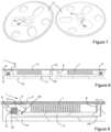
- THE figures 8 to 10 illustrate a second variant of a motor member 1 not forming the subject of the invention. This variant differs from that of Figures 1 to 7 mainly because its construction is the reverse of that of the latter.
- the fixed element 3 is a glass, which can be located either on the dial side or on the back side, and delimits the housing of the mainspring 7 on one of its sides.
- the barrel bridge 19 may be a separate element, secured to the plate or the back, or may have come in one piece with one of the latter.
- bridge used rather means a functional part of the structure of the driving member 1 which may be part of another element such as a plate or a back
- the barrel bridge 19 of this variant comprises a hollow 20 in its bottom, in which the toothed wheel 11 is located, which is pivoted around a fixed shaft 13 which said bridge 19 comprises.
- the axial positioning of the toothed wheel 11 is ensured on one side by a stop 33, and on the other side by the crystal 3.
- the drum 5 is superimposed on the toothed wheel 11, and is guided in rotation and axially by guide elements 17 similar to those of the first variant, and which also extend from the barrel bridge 19 towards the fixed element 3 in a direction parallel to the axis of rotation of the drum 5.
- the guide elements 17 cooperate with the shoulder 21 located on the drum 5 in order to ensure the positioning of the latter.
- the guide elements 17 are located in blind holes 35 which are deeper than necessary to receive the guide elements 17 in order to allow the watchmaker to adjust the height of the latter according to his needs.
- the blind holes 35 may have a sufficient depth to receive the guide elements 17 up to the bottom of the holes 35.
- the axial positioning of the toothed wheel 11 can be ensured not by the glass 3, but by the drum 5 which can serve as an axial stop.
- FIG 11 illustrates a variant of the drum 5 and the mainspring 7 which can be implemented in connection with all the aforementioned embodiments.
- the drum 5 and the mainspring 7 form a single-piece assembly, made in one piece.
- the inner end of the mainspring 7 also comprises a ferrule 7a allowing a kinematic connection with the toothed wheel 11, but this ferrule 7a can of course be omitted.
- the ferrule comprises a polygonal opening, but other known shapes are also possible.
- a mainspring 7 of this type may be made of metal, or of silicon-based material (e.g. amorphous, monocrystalline or polycrystalline silicon, its mono- or polycrystalline oxide, carbide or nitride), alumina, polymer, composite or the like.
- the construction of the illustrated drive member 1 includes numerous contact surfaces between moving parts, it could be advantageous to provide fine polishing or diamond plating of the contact surfaces, or to perform a surface treatment such as DLC (diamond-like carbon) deposition, nanostructuring, teflon plating, electroplating or ion implantation on one or more surfaces intended to undergo friction.
- a surface treatment such as DLC (diamond-like carbon) deposition, nanostructuring, teflon plating, electroplating or ion implantation on one or more surfaces intended to undergo friction.
- FIGS 12 to 14 illustrate a variant of a drive member 1 according to the invention.
- the toothed wheel 11 is supported on a fixed shaft 13 in a manner similar to the variant of Figures 1 to 3 , and the housing for the mainspring is defined on its two faces by the toothed wheel 11 as well as a fixed element 3 of the timepiece, such as a frame element.
- the drum 5 is held in its axial and radial positions by means of a ball bearing 37.
- This ball bearing 37 consists of a first groove 38a provided on the outer wall of the drum 5, and a second groove 38b formed in the inner face of an outer ring 39.
- the two grooves 38a, 38b are one facing the other. the other in order to define a cavity, and balls (not illustrated) are placed in this cavity in a generally known manner.
- the first groove 38a is formed by a first beveled surface 5a provided on the outer face of the drum 5, which is adjacent to a second beveled surface 41a with which an inner ring 41 is provided.
- the latter is driven, glued, welded or otherwise secured to the outer face of the drum 5, but it is also possible to form the first groove 38a directly in the body of the drum 5, which would therefore be in one piece.
- the outer ring 39 is held in place by a bridge 19 as well as screws 43, which hold it against a shoulder 45 provided on the fixed element 3 to which it is thus fixed.
- the drum 5 is thus suspended by the ball bearing 37, and does not come into contact with either the fixed element 3 or the toothed wheel 11. Consequently, and unlike the other variants described above, no additional guide member is necessary. The friction experienced by the drum during its pivoting can thus be reduced to a minimum value. Furthermore, this variant has an exceptionally thin thickness.
- FIG. 12 to 14 also illustrate the arrangement of the gears with the toothed wheel 11 and with the drum 5.
- a reference 47 which is in the same plane as the toothed wheel 11 which meshes with this last, as well as another reference 49 which is in the same plane as the teeth 6 of the drum 5 and also meshes therewith.
- the references 47, 49 therefore pass on either side of the outer ring 39.
- the drive member can be wound up by the drum 5 without requiring any pawl, thus reducing the number of components used in the construction. Furthermore, this arrangement eliminates the over-tension when winding the mainspring 7 by the dead angle of a one-way bearing.
- FIGS 15 to 16 illustrate an additional variant of a motor member 1 not forming the subject of the invention.
- This variant differs from that of the Figures 1 to 7 mainly in that the drum 5 is positioned radially by guide elements carried or integral with the fixed element 3, and axially on the one hand by the fixed element 3, on the other hand by the toothed wheel 11.
- the fixed element 3 comprises a recess 22 in which the drum 5 is placed.
- the side wall 22a of this recess 22 forms a guide element making it possible to radially position the drum 5 and to axially limit the position of the drum 5 in a first direction.
- Other forms of guide elements are also possible, such as for example studs integral with the fixed element 3 which take place in a circular groove provided in the lower face of the drum 5 or vice versa, or a system of one or more circular grooves or rails distributed between the fixed element 3 and the drum 5, which interact for the same purpose.
- the drum 5 simply abuts against the surface of the fixed element 3 and slides on the latter during its pivoting.
- guide members 17 such as stones on the drum 5 or on the fixed element 3, or to arrange a ball bearing in the lower face of the drum 5 in order to reduce friction.
- the axial displacement of the drum 5 is limited by the toothed wheel 11.
- the latter is supported on a fixed shaft 13 in a manner similar to the variant of Figures 1 to 3 , and said toothed wheel 11 has an external diameter large enough to cover or overlap, at least partially, an area of the drum 5.
- This covering, at least partial makes it possible to define a second axial stop for the drum 5 in the direction opposite to the axial stop previously defined by the hollow of the fixed element 3. In other words, the drum 5 is sandwiched between the fixed element 3 and the toothed wheel 11.
- this variant offers a reduced number of parts and makes it possible to do away with the need for a barrel bridge.
Landscapes
- Physics & Mathematics (AREA)
- General Physics & Mathematics (AREA)
- Engineering & Computer Science (AREA)
- Metallurgy (AREA)
- Connection Of Motors, Electrical Generators, Mechanical Devices, And The Like (AREA)
- Electromechanical Clocks (AREA)
- Transmission Devices (AREA)
Claims (6)
- Uhrwerk für eine Uhr, umfassend ein Antriebsorgan mit:- eine Antriebsfeder (7) ;- eine Trommel (5), die eine Außenwand einer die Antriebsfeder (7) aufnehmenden Aufnahme begrenzt, wobei ein äußeres Ende der Antriebsfeder (7) mit der Trommel (5) verbunden ist, wobei die Trommel (5) so angeordnet ist, um eine Drehachse zu rotieren, und die Form eines ringförmigen Zahnkranzes aufweist;- ein Zahnrad (11), das fest mit einem Federkern (9) verbunden ist, mit dem ein inneres Ende der Antriebsfeder (7) verbunden ist;wobei eine offene Seite der Aufnahme dazu bestimmt ist, geschlossen zu werden, indem sie gegenüber einem festen Element (3) der Uhr positioniert wird, wogegen die Trommel (5) montiert werden soll,dadurch gekennzeichnet, dass das Federkern (9) und das Zahnrad (11) einstückig sind,und dass die Trommel (5) von einem Kugellager (37) getragen wird, das eine erste Nut (38a), die sich an der Außenwand der Trommel befindet, und eine zweite Nut (38b), die der ersten Nut (38a) gegenüberliegt, umfasst, wobei sich die zweite Nut (38b) an der Innenwand eines Außenrings (39) befindet, der so angeordnet ist, dass er an dem festen Element (3) befestigt werden kann, wobei eine Vielzahl von Kugeln in dem durch die Nuten (38a, 38b) gebildeten Hohlraum untergebracht sind.
- Uhrwerk (1) nach Anspruch 1, wobei die Trommel (5) und die Antriebsfeder (7) einstückig sind.
- Uhrwerk nach einem der Ansprüche 1 oder 2,wobei das Zahnrad (11) rotierbar auf einer festen Welle (13) gelagert ist, die sich von einem des festen Elements (3) oder der Federhausbrücke (19) hinaus erstreckt.
- Uhrwerk nach einem der Ansprüche 1 bis 3, wobei das feste Element (3) ein Gestellelement des Uhrwerks ist.
- Uhr, die ein Uhrwerk nach einem der Ansprüche 1 bis 4 umfasst.
- Uhr nach Anspruch 5, wobei das feste Element ein Glas (3) ist, das die Uhr aufweist, oder ein Boden ist, der die Uhr aufweist.
Applications Claiming Priority (2)
| Application Number | Priority Date | Filing Date | Title |
|---|---|---|---|
| CH00698/16A CH712519B8 (fr) | 2016-06-01 | 2016-06-01 | Organe moteur pour pièce d'horlogerie. |
| EP17171580.8A EP3252540B1 (de) | 2016-06-01 | 2017-05-17 | Motororgan für uhr |
Related Parent Applications (2)
| Application Number | Title | Priority Date | Filing Date |
|---|---|---|---|
| EP17171580.8A Division EP3252540B1 (de) | 2016-06-01 | 2017-05-17 | Motororgan für uhr |
| EP17171580.8A Division-Into EP3252540B1 (de) | 2016-06-01 | 2017-05-17 | Motororgan für uhr |
Publications (2)
| Publication Number | Publication Date |
|---|---|
| EP3889689A1 EP3889689A1 (de) | 2021-10-06 |
| EP3889689B1 true EP3889689B1 (de) | 2025-02-19 |
Family
ID=56344943
Family Applications (3)
| Application Number | Title | Priority Date | Filing Date |
|---|---|---|---|
| EP17171580.8A Active EP3252540B1 (de) | 2016-06-01 | 2017-05-17 | Motororgan für uhr |
| EP21168544.1A Active EP3889689B1 (de) | 2016-06-01 | 2017-05-17 | Antriebsorgan für uhr |
| EP21168538.3A Active EP3889688B1 (de) | 2016-06-01 | 2017-05-17 | Antriebsorgan für uhr |
Family Applications Before (1)
| Application Number | Title | Priority Date | Filing Date |
|---|---|---|---|
| EP17171580.8A Active EP3252540B1 (de) | 2016-06-01 | 2017-05-17 | Motororgan für uhr |
Family Applications After (1)
| Application Number | Title | Priority Date | Filing Date |
|---|---|---|---|
| EP21168538.3A Active EP3889688B1 (de) | 2016-06-01 | 2017-05-17 | Antriebsorgan für uhr |
Country Status (2)
| Country | Link |
|---|---|
| EP (3) | EP3252540B1 (de) |
| CH (1) | CH712519B8 (de) |
Families Citing this family (5)
| Publication number | Priority date | Publication date | Assignee | Title |
|---|---|---|---|---|
| CN112363376B (zh) * | 2020-11-04 | 2025-07-08 | 天王电子(深圳)有限公司 | 一种表 |
| EP4206825B1 (de) * | 2021-12-29 | 2025-04-30 | Nivarox-FAR S.A. | Federhaus für einen zeitmesser |
| USD1015914S1 (en) * | 2022-06-29 | 2024-02-27 | Turlen Holding Sa | Watch movement |
| CH721458A1 (fr) * | 2023-12-22 | 2025-06-30 | Richemont Int Sa | Organe moteur de dispositif horloger |
| EP4733854A1 (de) * | 2024-10-22 | 2026-04-29 | Nivarox-FAR S.A. | Verfahren zur herstellung einer zylinderwelle |
Citations (3)
| Publication number | Priority date | Publication date | Assignee | Title |
|---|---|---|---|---|
| FR2341885A1 (fr) * | 1976-02-18 | 1977-09-16 | Bouchet Lassale Sa | Dispositif de pivotement pour barillet de montre |
| EP2577404A1 (de) * | 2010-05-27 | 2013-04-10 | Association Suisse pour la Recherche Horlogère | Tonnenfeder |
| EP3021172A1 (de) * | 2014-11-11 | 2016-05-18 | Montres Breguet SA | Antriebsorgan für Uhrwerk |
Family Cites Families (7)
| Publication number | Priority date | Publication date | Assignee | Title |
|---|---|---|---|---|
| CH26510A (fr) | 1902-11-08 | 1903-09-15 | Henri Sandoz | Barillet de montre |
| CH28684A (fr) | 1903-07-23 | 1904-06-15 | Meyer Graber C | Barillet de montre |
| CH46863A (fr) | 1908-09-26 | 1910-04-16 | Maire Favre E | Montre à marche de longue durée |
| CH334702A (fr) * | 1957-12-03 | 1958-12-15 | Rolex Montres | Pièce d'horlogerie |
| CH581342B5 (de) * | 1973-05-10 | 1976-10-29 | Ebauches Sa | |
| US9298162B2 (en) * | 2010-10-01 | 2016-03-29 | Rolex Sa | Timepiece barrel with thin disks |
| CH705491A2 (fr) * | 2011-09-15 | 2013-03-15 | Montres Breguet Sa | Ensemble barillet d'horlogerie à diamètre de bonde réduit. |
-
2016
- 2016-06-01 CH CH00698/16A patent/CH712519B8/fr unknown
-
2017
- 2017-05-17 EP EP17171580.8A patent/EP3252540B1/de active Active
- 2017-05-17 EP EP21168544.1A patent/EP3889689B1/de active Active
- 2017-05-17 EP EP21168538.3A patent/EP3889688B1/de active Active
Patent Citations (4)
| Publication number | Priority date | Publication date | Assignee | Title |
|---|---|---|---|---|
| FR2341885A1 (fr) * | 1976-02-18 | 1977-09-16 | Bouchet Lassale Sa | Dispositif de pivotement pour barillet de montre |
| EP2577404A1 (de) * | 2010-05-27 | 2013-04-10 | Association Suisse pour la Recherche Horlogère | Tonnenfeder |
| EP2577404B1 (de) * | 2010-05-27 | 2016-10-05 | Association Suisse pour la Recherche Horlogère (ASRH) | Tonnenfeder |
| EP3021172A1 (de) * | 2014-11-11 | 2016-05-18 | Montres Breguet SA | Antriebsorgan für Uhrwerk |
Also Published As
| Publication number | Publication date |
|---|---|
| CH712519B1 (fr) | 2023-01-31 |
| CH712519A1 (fr) | 2017-12-15 |
| CH712519B8 (fr) | 2023-03-31 |
| EP3889688A1 (de) | 2021-10-06 |
| EP3889689A1 (de) | 2021-10-06 |
| EP3252540A1 (de) | 2017-12-06 |
| EP3889688B1 (de) | 2023-04-26 |
| EP3252540B1 (de) | 2021-06-23 |
Similar Documents
| Publication | Publication Date | Title |
|---|---|---|
| EP2437125B1 (de) | Uhr | |
| EP3252540B1 (de) | Motororgan für uhr | |
| EP2823364B1 (de) | Federhaus | |
| EP2859412B1 (de) | System eines drehbaren aussenrings (einer uhr) | |
| EP2080066B1 (de) | Uhr | |
| EP1843225B1 (de) | Mechanischer Wechsler zum Drehantreiben eines Rades aus einer einzelnen Richtung | |
| EP2350745B1 (de) | Antriebsmechanismus für ein uhrwerk | |
| EP2255257A1 (de) | Schwenkelement | |
| EP2564276B1 (de) | Uhr | |
| EP3964896B1 (de) | Automatischer aufziehmechanismus einer armbanduhr mit einer schwungmasse | |
| CH715052A2 (fr) | Mécanisme à couple constant, mouvement de pièce d'horlogerie, et pièce d'horlogerie. | |
| EP2214064A1 (de) | Uhrwerk | |
| EP2869134B1 (de) | Federhaussystem für Uhr | |
| EP3742236B1 (de) | Uhrvorrichtung, die eine erste komponente umfasst, die auf einer zweiten komponente durch plastische verformung fixiert ist | |
| EP3654109B1 (de) | Uhr, die zwei energiequellen besitzt | |
| CH719486B1 (fr) | Assemblage horloger d'un arbre sur une ébauche. | |
| EP4607290A1 (de) | Uhrwerk, hemmung für uhr und uhr mit solch einem hemmungsteil | |
| EP4740068A1 (de) | Hemmungssystem für eine uhr | |
| CH701239A2 (fr) | Mecanisme de remontage automatique pour mouvement horloger. | |
| WO2023170159A1 (fr) | Assemblage horloger | |
| CH706474B1 (fr) | Pièce d'horlogerie comportant un mouvement de base et un mécanisme additionnel interchangeable. | |
| CH716502A2 (fr) | Mouvement d'horlogerie mécanique à remontage automatique. | |
| EP3714336A1 (de) | Halterung für ein eine anzeigescheibe tragendes rad | |
| CH700802B1 (fr) | Masse oscillante pour recharger la source d'énergie d'un instrument portable. | |
| EP3974913A1 (de) | Federgehäuse für uhr |
Legal Events
| Date | Code | Title | Description |
|---|---|---|---|
| PUAI | Public reference made under article 153(3) epc to a published international application that has entered the european phase |
Free format text: ORIGINAL CODE: 0009012 |
|
| STAA | Information on the status of an ep patent application or granted ep patent |
Free format text: STATUS: THE APPLICATION HAS BEEN PUBLISHED |
|
| AC | Divisional application: reference to earlier application |
Ref document number: 3252540 Country of ref document: EP Kind code of ref document: P |
|
| AK | Designated contracting states |
Kind code of ref document: A1 Designated state(s): AL AT BE BG CH CY CZ DE DK EE ES FI FR GB GR HR HU IE IS IT LI LT LU LV MC MK MT NL NO PL PT RO RS SE SI SK SM TR |
|
| STAA | Information on the status of an ep patent application or granted ep patent |
Free format text: STATUS: REQUEST FOR EXAMINATION WAS MADE |
|
| 17P | Request for examination filed |
Effective date: 20220127 |
|
| RBV | Designated contracting states (corrected) |
Designated state(s): AL AT BE BG CH CY CZ DE DK EE ES FI FR GB GR HR HU IE IS IT LI LT LU LV MC MK MT NL NO PL PT RO RS SE SI SK SM TR |
|
| REG | Reference to a national code |
Ref country code: HK Ref legal event code: DE Ref document number: 40058102 Country of ref document: HK |
|
| STAA | Information on the status of an ep patent application or granted ep patent |
Free format text: STATUS: EXAMINATION IS IN PROGRESS |
|
| 17Q | First examination report despatched |
Effective date: 20230301 |
|
| GRAP | Despatch of communication of intention to grant a patent |
Free format text: ORIGINAL CODE: EPIDOSNIGR1 |
|
| STAA | Information on the status of an ep patent application or granted ep patent |
Free format text: STATUS: GRANT OF PATENT IS INTENDED |
|
| INTG | Intention to grant announced |
Effective date: 20241025 |
|
| GRAS | Grant fee paid |
Free format text: ORIGINAL CODE: EPIDOSNIGR3 |
|
| GRAA | (expected) grant |
Free format text: ORIGINAL CODE: 0009210 |
|
| STAA | Information on the status of an ep patent application or granted ep patent |
Free format text: STATUS: THE PATENT HAS BEEN GRANTED |
|
| AC | Divisional application: reference to earlier application |
Ref document number: 3252540 Country of ref document: EP Kind code of ref document: P |
|
| AK | Designated contracting states |
Kind code of ref document: B1 Designated state(s): AL AT BE BG CH CY CZ DE DK EE ES FI FR GB GR HR HU IE IS IT LI LT LU LV MC MK MT NL NO PL PT RO RS SE SI SK SM TR |
|
| REG | Reference to a national code |
Ref country code: GB Ref legal event code: FG4D Free format text: NOT ENGLISH |
|
| REG | Reference to a national code |
Ref country code: CH Ref legal event code: EP |
|
| REG | Reference to a national code |
Ref country code: IE Ref legal event code: FG4D Free format text: LANGUAGE OF EP DOCUMENT: FRENCH |
|
| REG | Reference to a national code |
Ref country code: DE Ref legal event code: R096 Ref document number: 602017087957 Country of ref document: DE |
|
| REG | Reference to a national code |
Ref country code: NL Ref legal event code: MP Effective date: 20250219 |
|
| PG25 | Lapsed in a contracting state [announced via postgrant information from national office to epo] |
Ref country code: RS Free format text: LAPSE BECAUSE OF FAILURE TO SUBMIT A TRANSLATION OF THE DESCRIPTION OR TO PAY THE FEE WITHIN THE PRESCRIBED TIME-LIMIT Effective date: 20250519 |
|
| PG25 | Lapsed in a contracting state [announced via postgrant information from national office to epo] |
Ref country code: FI Free format text: LAPSE BECAUSE OF FAILURE TO SUBMIT A TRANSLATION OF THE DESCRIPTION OR TO PAY THE FEE WITHIN THE PRESCRIBED TIME-LIMIT Effective date: 20250219 |
|
| PG25 | Lapsed in a contracting state [announced via postgrant information from national office to epo] |
Ref country code: PL Free format text: LAPSE BECAUSE OF FAILURE TO SUBMIT A TRANSLATION OF THE DESCRIPTION OR TO PAY THE FEE WITHIN THE PRESCRIBED TIME-LIMIT Effective date: 20250219 |
|
| PGFP | Annual fee paid to national office [announced via postgrant information from national office to epo] |
Ref country code: DE Payment date: 20250521 Year of fee payment: 9 |
|
| PG25 | Lapsed in a contracting state [announced via postgrant information from national office to epo] |
Ref country code: ES Free format text: LAPSE BECAUSE OF FAILURE TO SUBMIT A TRANSLATION OF THE DESCRIPTION OR TO PAY THE FEE WITHIN THE PRESCRIBED TIME-LIMIT Effective date: 20250219 |
|
| PGFP | Annual fee paid to national office [announced via postgrant information from national office to epo] |
Ref country code: GB Payment date: 20250527 Year of fee payment: 9 |
|
| REG | Reference to a national code |
Ref country code: LT Ref legal event code: MG9D |
|
| PG25 | Lapsed in a contracting state [announced via postgrant information from national office to epo] |
Ref country code: IS Free format text: LAPSE BECAUSE OF FAILURE TO SUBMIT A TRANSLATION OF THE DESCRIPTION OR TO PAY THE FEE WITHIN THE PRESCRIBED TIME-LIMIT Effective date: 20250619 Ref country code: NO Free format text: LAPSE BECAUSE OF FAILURE TO SUBMIT A TRANSLATION OF THE DESCRIPTION OR TO PAY THE FEE WITHIN THE PRESCRIBED TIME-LIMIT Effective date: 20250519 |
|
| PG25 | Lapsed in a contracting state [announced via postgrant information from national office to epo] |
Ref country code: NL Free format text: LAPSE BECAUSE OF FAILURE TO SUBMIT A TRANSLATION OF THE DESCRIPTION OR TO PAY THE FEE WITHIN THE PRESCRIBED TIME-LIMIT Effective date: 20250219 |
|
| PG25 | Lapsed in a contracting state [announced via postgrant information from national office to epo] |
Ref country code: HR Free format text: LAPSE BECAUSE OF FAILURE TO SUBMIT A TRANSLATION OF THE DESCRIPTION OR TO PAY THE FEE WITHIN THE PRESCRIBED TIME-LIMIT Effective date: 20250219 |
|
| PG25 | Lapsed in a contracting state [announced via postgrant information from national office to epo] |
Ref country code: LV Free format text: LAPSE BECAUSE OF FAILURE TO SUBMIT A TRANSLATION OF THE DESCRIPTION OR TO PAY THE FEE WITHIN THE PRESCRIBED TIME-LIMIT Effective date: 20250219 Ref country code: PT Free format text: LAPSE BECAUSE OF FAILURE TO SUBMIT A TRANSLATION OF THE DESCRIPTION OR TO PAY THE FEE WITHIN THE PRESCRIBED TIME-LIMIT Effective date: 20250620 |
|
| PGFP | Annual fee paid to national office [announced via postgrant information from national office to epo] |
Ref country code: FR Payment date: 20250528 Year of fee payment: 9 |
|
| PG25 | Lapsed in a contracting state [announced via postgrant information from national office to epo] |
Ref country code: GR Free format text: LAPSE BECAUSE OF FAILURE TO SUBMIT A TRANSLATION OF THE DESCRIPTION OR TO PAY THE FEE WITHIN THE PRESCRIBED TIME-LIMIT Effective date: 20250520 Ref country code: BG Free format text: LAPSE BECAUSE OF FAILURE TO SUBMIT A TRANSLATION OF THE DESCRIPTION OR TO PAY THE FEE WITHIN THE PRESCRIBED TIME-LIMIT Effective date: 20250219 |
|
| PGFP | Annual fee paid to national office [announced via postgrant information from national office to epo] |
Ref country code: CH Payment date: 20250601 Year of fee payment: 9 |
|
| REG | Reference to a national code |
Ref country code: AT Ref legal event code: MK05 Ref document number: 1768846 Country of ref document: AT Kind code of ref document: T Effective date: 20250219 |
|
| PG25 | Lapsed in a contracting state [announced via postgrant information from national office to epo] |
Ref country code: SE Free format text: LAPSE BECAUSE OF FAILURE TO SUBMIT A TRANSLATION OF THE DESCRIPTION OR TO PAY THE FEE WITHIN THE PRESCRIBED TIME-LIMIT Effective date: 20250219 |
|
| PG25 | Lapsed in a contracting state [announced via postgrant information from national office to epo] |
Ref country code: SM Free format text: LAPSE BECAUSE OF FAILURE TO SUBMIT A TRANSLATION OF THE DESCRIPTION OR TO PAY THE FEE WITHIN THE PRESCRIBED TIME-LIMIT Effective date: 20250219 |
|
| PG25 | Lapsed in a contracting state [announced via postgrant information from national office to epo] |
Ref country code: DK Free format text: LAPSE BECAUSE OF FAILURE TO SUBMIT A TRANSLATION OF THE DESCRIPTION OR TO PAY THE FEE WITHIN THE PRESCRIBED TIME-LIMIT Effective date: 20250219 |
|
| PG25 | Lapsed in a contracting state [announced via postgrant information from national office to epo] |
Ref country code: IT Free format text: LAPSE BECAUSE OF FAILURE TO SUBMIT A TRANSLATION OF THE DESCRIPTION OR TO PAY THE FEE WITHIN THE PRESCRIBED TIME-LIMIT Effective date: 20250219 |
|
| PG25 | Lapsed in a contracting state [announced via postgrant information from national office to epo] |
Ref country code: AT Free format text: LAPSE BECAUSE OF FAILURE TO SUBMIT A TRANSLATION OF THE DESCRIPTION OR TO PAY THE FEE WITHIN THE PRESCRIBED TIME-LIMIT Effective date: 20250219 |
|
| PG25 | Lapsed in a contracting state [announced via postgrant information from national office to epo] |
Ref country code: CZ Free format text: LAPSE BECAUSE OF FAILURE TO SUBMIT A TRANSLATION OF THE DESCRIPTION OR TO PAY THE FEE WITHIN THE PRESCRIBED TIME-LIMIT Effective date: 20250219 Ref country code: EE Free format text: LAPSE BECAUSE OF FAILURE TO SUBMIT A TRANSLATION OF THE DESCRIPTION OR TO PAY THE FEE WITHIN THE PRESCRIBED TIME-LIMIT Effective date: 20250219 |
|
| PG25 | Lapsed in a contracting state [announced via postgrant information from national office to epo] |
Ref country code: RO Free format text: LAPSE BECAUSE OF FAILURE TO SUBMIT A TRANSLATION OF THE DESCRIPTION OR TO PAY THE FEE WITHIN THE PRESCRIBED TIME-LIMIT Effective date: 20250219 |
|
| PG25 | Lapsed in a contracting state [announced via postgrant information from national office to epo] |
Ref country code: SK Free format text: LAPSE BECAUSE OF FAILURE TO SUBMIT A TRANSLATION OF THE DESCRIPTION OR TO PAY THE FEE WITHIN THE PRESCRIBED TIME-LIMIT Effective date: 20250219 |
|
| REG | Reference to a national code |
Ref country code: DE Ref legal event code: R097 Ref document number: 602017087957 Country of ref document: DE |
|
| PLBE | No opposition filed within time limit |
Free format text: ORIGINAL CODE: 0009261 |
|
| STAA | Information on the status of an ep patent application or granted ep patent |
Free format text: STATUS: NO OPPOSITION FILED WITHIN TIME LIMIT |
|
| PG25 | Lapsed in a contracting state [announced via postgrant information from national office to epo] |
Ref country code: LU Free format text: LAPSE BECAUSE OF NON-PAYMENT OF DUE FEES Effective date: 20250517 |
|
| 26N | No opposition filed |
Effective date: 20251120 |
|
| REG | Reference to a national code |
Ref country code: BE Ref legal event code: MM Effective date: 20250531 |
|
| PG25 | Lapsed in a contracting state [announced via postgrant information from national office to epo] |
Ref country code: MC Free format text: LAPSE BECAUSE OF FAILURE TO SUBMIT A TRANSLATION OF THE DESCRIPTION OR TO PAY THE FEE WITHIN THE PRESCRIBED TIME-LIMIT Effective date: 20250219 |
|
| PG25 | Lapsed in a contracting state [announced via postgrant information from national office to epo] |
Ref country code: IE Free format text: LAPSE BECAUSE OF NON-PAYMENT OF DUE FEES Effective date: 20250517 |
|
| PG25 | Lapsed in a contracting state [announced via postgrant information from national office to epo] |
Ref country code: BE Free format text: LAPSE BECAUSE OF NON-PAYMENT OF DUE FEES Effective date: 20250531 |