EP2658041A1 - Connecteur de type levier et couvre-fils - Google Patents
Connecteur de type levier et couvre-fils Download PDFInfo
- Publication number
- EP2658041A1 EP2658041A1 EP11850760.7A EP11850760A EP2658041A1 EP 2658041 A1 EP2658041 A1 EP 2658041A1 EP 11850760 A EP11850760 A EP 11850760A EP 2658041 A1 EP2658041 A1 EP 2658041A1
- Authority
- EP
- European Patent Office
- Prior art keywords
- lever
- shaft
- guide
- housing
- accommodating groove
- Prior art date
- Legal status (The legal status is an assumption and is not a legal conclusion. Google has not performed a legal analysis and makes no representation as to the accuracy of the status listed.)
- Granted
Links
Images



Classifications
-
- H—ELECTRICITY
- H01—ELECTRIC ELEMENTS
- H01R—ELECTRICALLY-CONDUCTIVE CONNECTIONS; STRUCTURAL ASSOCIATIONS OF A PLURALITY OF MUTUALLY-INSULATED ELECTRICAL CONNECTING ELEMENTS; COUPLING DEVICES; CURRENT COLLECTORS
- H01R13/00—Details of coupling devices of the kinds covered by groups H01R12/70 or H01R24/00 - H01R33/00
- H01R13/62—Means for facilitating engagement or disengagement of coupling parts or for holding them in engagement
- H01R13/629—Additional means for facilitating engagement or disengagement of coupling parts, e.g. aligning or guiding means, levers, gas pressure electrical locking indicators, manufacturing tolerances
- H01R13/62977—Pivoting levers actuating linearly camming means
-
- H—ELECTRICITY
- H01—ELECTRIC ELEMENTS
- H01R—ELECTRICALLY-CONDUCTIVE CONNECTIONS; STRUCTURAL ASSOCIATIONS OF A PLURALITY OF MUTUALLY-INSULATED ELECTRICAL CONNECTING ELEMENTS; COUPLING DEVICES; CURRENT COLLECTORS
- H01R13/00—Details of coupling devices of the kinds covered by groups H01R12/70 or H01R24/00 - H01R33/00
- H01R13/62—Means for facilitating engagement or disengagement of coupling parts or for holding them in engagement
- H01R13/629—Additional means for facilitating engagement or disengagement of coupling parts, e.g. aligning or guiding means, levers, gas pressure electrical locking indicators, manufacturing tolerances
- H01R13/62933—Comprising exclusively pivoting lever
-
- H—ELECTRICITY
- H01—ELECTRIC ELEMENTS
- H01R—ELECTRICALLY-CONDUCTIVE CONNECTIONS; STRUCTURAL ASSOCIATIONS OF A PLURALITY OF MUTUALLY-INSULATED ELECTRICAL CONNECTING ELEMENTS; COUPLING DEVICES; CURRENT COLLECTORS
- H01R13/00—Details of coupling devices of the kinds covered by groups H01R12/70 or H01R24/00 - H01R33/00
- H01R13/44—Means for preventing access to live contacts
-
- H—ELECTRICITY
- H01—ELECTRIC ELEMENTS
- H01R—ELECTRICALLY-CONDUCTIVE CONNECTIONS; STRUCTURAL ASSOCIATIONS OF A PLURALITY OF MUTUALLY-INSULATED ELECTRICAL CONNECTING ELEMENTS; COUPLING DEVICES; CURRENT COLLECTORS
- H01R13/00—Details of coupling devices of the kinds covered by groups H01R12/70 or H01R24/00 - H01R33/00
- H01R13/44—Means for preventing access to live contacts
- H01R13/447—Shutter or cover plate
-
- H—ELECTRICITY
- H01—ELECTRIC ELEMENTS
- H01R—ELECTRICALLY-CONDUCTIVE CONNECTIONS; STRUCTURAL ASSOCIATIONS OF A PLURALITY OF MUTUALLY-INSULATED ELECTRICAL CONNECTING ELEMENTS; COUPLING DEVICES; CURRENT COLLECTORS
- H01R13/00—Details of coupling devices of the kinds covered by groups H01R12/70 or H01R24/00 - H01R33/00
- H01R13/62—Means for facilitating engagement or disengagement of coupling parts or for holding them in engagement
- H01R13/629—Additional means for facilitating engagement or disengagement of coupling parts, e.g. aligning or guiding means, levers, gas pressure electrical locking indicators, manufacturing tolerances
- H01R13/62933—Comprising exclusively pivoting lever
- H01R13/62955—Pivoting lever comprising supplementary/additional locking means
Definitions
- the present invention relates to a lever-type connector and a wire cover for covering a plurality of electric wires.
- a lever 2 of a lever-type connector 1 has a pair of side plates 2a and a connecting part 2b for connecting both the side plates to each other, and is formed into a U shape. Also, on each of the inner surfaces in the tip end portions of both the side plates 2a, there is provided a rotating shaft 4 for attaching the lever 2 to a housing 3 of the lever-type connector 1.
- a part 2c of the lever 2 interferes with a wire cover 7 attached to the housing 3, so that, in some cases, the tilt angle of the lever 2 cannot be made an angle such that the rotating shafts 4 coincide with the shaft bearing groove 6. Further, if an attempt is made to forcedly insert the rotating shafts 4 of the lever 2 into the shaft bearing groove 6, the lever 2 may be damaged, or the shaft bearing groove 6 may be deformed.
- the present invention has been made to solve the above-described problems, and accordingly an object thereof is to provide a lever-type connector and a wire cover, which makes it possible to easily and reliably mount a lever to the wire cover.
- the present invention made to achieve the above object provides a lever-type connector including a housing for accommodating contacts; a wire cover attached on the back surface side of the housing to cover electric wires connected to the contacts accommodated in the housing; and a lever that is provided with a shaft part on one end side, and is provided so as to be rotatable with respect to the housing with the shaft part being the center by inserting the shaft part in a shaft accommodating groove formed in the housing, characterized in that the lever is formed with a protrusion projecting to the housing side; the wire cover is formed with a guide part against which the protrusion butts when the lever is made at a predetermined angle when the shaft part is inserted into the shaft accommodating groove; and the guide part has a guide surface continuous along the direction in which the shaft part is inserted into the shaft accommodating groove, and a stopper surface that is formed in the end portion on the side opposite to the shaft accommodating groove of the guide surface so as to intersect at right angles to the guide surface or make an acute angle with the guide surface, and inhibits the shaft part from
- the tilt angle of the lever with respect to the housing can be determined. Also, since the stopper surface, which intersects at right angles to the guide surface or makes an acute angle with the guide surface, inhibits the shaft part from moving in the direction in which the shaft part separates from the shaft accommodating groove, the lever can be prevented from being caused to come off or tilt inadvertently.
- the present invention provides a wire cover used for the lever-type connector described above, including a cover body for accommodating a plurality of electric wires connected to connected objects therein; a wire outlet for pulling out the plurality of electric wires from the interior of the cover body to the outside; a hood part which is formed so as to project from the periphery of the wire outlet to regulate the pullout direction of the plurality of electric wires, and to which the plurality of electric wires are fixed; and a guide part against which the protrusion butts when the lever is made at a predetermined angle when the shaft part is inserted into the shaft accommodating groove, characterized in that the guide part has a guide surface continuous along the direction in which the shaft part is inserted into the shaft accommodating groove, and a stopper surface that is formed in the end portion on the side opposite to the shaft accommodating groove of the guide surface so as to intersect at right angles to the guide surface or make an acute angle with the guide surface, and inhibits the shaft part from moving in the direction in which the shaft part separates from the shaft accommodating groove
- the tilt angle of the lever with respect to the housing can be determined. Also, since the stopper surface inhibits the shaft part from moving in the direction in which the shaft part separates from the shaft accommodating groove, the lever can be prevented from being caused to come off or tilt inadvertently. Thus, the lever can be mounted to the wire cover easily and reliably.
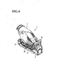
- a lever-type connector 100 includes a housing 10 accommodating a plurality of contacts (not shown), a wire cover 20 mounted to one surface side of the housing 10, and a lever 30 attached to the housing 10.
- the housing 10 has a plurality of contact accommodating holes 11 penetrating in a direction such that a facing surface 10a facing to the wire cover 20 and an opposite surface 10b thereof are connected to each other.
- the facing surface 10a and the opposite surface 10b each have a rectangular shape that is long in one direction.
- the housing 10 is provided with slider accommodating slots 12, which extend along a longitudinal direction of the facing surface 10a, on both sides of the facing surface 10a.
- a plate-shaped slider 13 is accommodated so as to be movable in the direction in which the slider accommodating slot 12 continues.
- the slider 13 is formed into a flat plate shape, and is provided with a plurality of cam grooves (not shown) that draw in and push out cam pins (not shown) provided on the mating connector.
- a shaft bearing groove 15 in which a slider moving shaft 35, described later, of the lever 30 is supported so as to be rotatable.
- This shaft bearing groove 15 is provided so as to be exposed to the outside from the slider accommodating slot 12 in the state in which the slider 13 is accommodated in the slider accommodating slot 12.
- a shaft bearing groove (shaft accommodating groove) 16 in which a rotating shaft (shaft part) 34, described later, of the lever 30 is supported so as to be turnable.
- the lever 30 has a pair of side plates 32 extending in parallel with each other and a connecting part 33 for connecting the other ends of both the side plates 32 to each other to form a U shape.
- each of both the side plates 32 there is formed a stay part 32a extending to the direction tilted at a fixed angle with respect to the direction to which both the side plate 32 extend.
- the slider moving shaft 35 On the outer surface of the stay part 32a, the slider moving shaft 35, which is fitted in the shaft bearing groove 15 in the slider 13, is formed so as to project toward the outside, and on the inner surface thereof, the rotating shaft 34, which is fitted in the shaft bearing groove 16 in the housing 10, is formed so as to project toward the inside.
- a connecting plate 37 extending toward the inside is provided.
- a flat plane part 38 is formed on the inner surface on one end side of each of both the side plates 32.
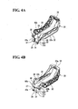
- a guide protrusion (protrusion) 60 is formed in the region facing to the rotating shaft 34 and the slider moving shaft 35. This guide protrusion 60 is formed so as to project toward the inside with respect to the flat plane part 38.
- the guide protrusion 60 has a flat plane-shaped guided surface 60a, which intersects at right angles to the flat plane part 38, on the flat plane part 38 side. Also, a backup surface 60b is formed so as to be adjacent to the guided surface 60a, intersect at right angles to the flat plane part 38, and make an acute angle with the guided surface 60a.
- the connecting part 33 is provided with a concave part 33a to which a locking piece 27b of a locking member 27, described later, of the wire cover 20 is locked.
- the wire cover 20 has a cover body 21 that covers a plurality of electric wires (not shown) connected to the contacts accommodated in the housing 10 and accommodates the electric wires therein, and stopper parts 22 provided on both sides of the cover body 21.
- the thickness of the cover body 21 is formed so as to be smaller than the space between both the side plates 32 of the lever 30.
- the stopper parts 22 are formed so as to be larger than the space between both the side plates 32 of the lever 30, thereby regulating the rotation angle to the direction to which the lever 30 is pulled up.
- a wire outlet 24 that allows the electric wires connected to the contacts accommodated in the housing 10 to be pulled out to the outside in a state of being bundled. Also, around the wire outlet 24 of the stopper parts 22, a hood part 25 projecting toward one side is provided.
- a guide part 70 for regulating the angle of the lever 30 when the slider moving shafts 35 and the rotating shafts 34 are fitted in the shaft bearing grooves 15 and 16.
- This guide part 70 has a straight line-shaped guide surface 70a that is formed along the direction in which the slider moving shafts 35 and the rotating shafts 34 are inserted into the shaft bearing grooves 15 and 16, and a stopper surface 70b that is formed so as to be continuous with the end portion on the side of separating from the slider moving shafts 35 and the rotating shafts 34 of the guide surface 70a, and to intersect at right angles to the guide surface 70a or make an acute crossing angle ⁇ with the guide surface 70a.
- the locking member 27 is formed into a plate spring form of a cantilever, and has a plate spring 27a, the locking piece 27b provided on the plate spring 27a, and a releasing convex part 27c.
- the locking piece 27b is provided so as to lock the lever 30 to the concave part 33a in the connecting part 33 when the lever 30 is tilted down.
- the releasing convex part 27c releases the locking of the locking piece 27b to the concave part 33a in the connecting part 33 due to the elastic deformation of the plate spring 27a caused by the pressing thereof.
- the cover body 21 is provided with locking convex parts 28 for inhibiting the lever 30 in a pulled-up state from being tilted down.
- Each of the locking convex parts 28 is provided so as to be locked to a step part 32b formed on each of the side plates 32 of the lever 30.
- the contacts connected to the electric wires are accommodated in the plurality of contact accommodating holes 11 in the housing 10. Also, the sliders 13 are inserted into both the slider accommodating slots 12 in the housing 10.
- the wire cover 20 is mounted to the housing 10 in which the plurality of contacts has been accommodated.
- the electric wires connected to the plurality of contacts accommodated in the housing 10 are accommodated in the wire cover 20 in a state of being bundled, and are pulled out to the outside through the wire outlet 24.
- the lever 30 is attached to the housing 10 to which the wire cover 20 has been mounted.
- the lever 30 When the lever 30 is attached to the housing 10 to which the wire cover 20 has been mounted, the lever 30 must be arranged so as to be in the state in which both the side plates 32 are laid across the back surface side of the wire cover 20 so that the wire cover 20 is held between both the side plates 32.
- the rotating shafts 34 on both the side plates 32 of the lever 30 are fitted in the shaft bearing grooves 16 in the housing 10, and the slider moving shafts 35 on both the side plates 32 of the lever 30 are fitted in the shaft bearing grooves 15 in the sliders 13.
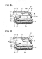
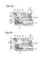
- the wire cover 20 is provided with the guide part 70, and by pressing the guide protrusions 60 of the lever 30 against the guide part 70, the tilt angle of the lever 30 is determined. More specifically, by butting the guided surfaces 60a of the guide protrusions 60 against the guide surface 70a of the guide part 70, the tilt angle of the lever 30 with respect to the wire cover 20 is determined.
- the lever 30 is slid along the guide surface 70a in this state, the slider moving shafts 35 and the rotating shafts 34 can be fitted in the shaft bearing grooves 15 and 16.
- lever 30 is attached to the wire cover 20, and the assembly of the lever-type connector 100 is completed.
- the lever 30 can be fitted in the shaft bearing grooves 15 and 16 easily and reliably. As the result, the assemblability of the lever-type connector 100 is improved.
- the guide part 70 is formed with the stopper surface 70b, if the lever 30 is going to move to the direction reverse to the direction in which the slider moving shafts 35 and the rotating shafts 34 are fitted in the shaft bearing grooves 15 and 16, the guide protrusions 60 collide with the stopper surface 70b. Further, since the stopper surface 70b is at right angles to the guide surface 70a, the guide protrusions 60 are less liable to come off the guide part 70.
- the guide part 70 is substantially of an L shape consisting of the guide surface 70a and the stopper surface 70b.
- the stopper surface 70b may be formed so as to make an acute angle with the guide surface 70a, or the guide part 70 may be made such as to substantially have a J shape or the like shape by providing an extension portion, which extends to the shaft bearing grooves 15 and 16 side, in the tip end portion of the stopper surface 70b, thereby more reliably preventing the guide protrusions 60 from coming off the guide part 70 when the lever 30 is mounted.
- the configuration of the lever-type connector 100 has been explained.
- the housing 10, the wire cover 20, and the lever 30 may have any configuration.
- Reference Signs List 10 ... housing, 15 ... shaft bearing groove, 16 ... shaft bearing groove (shaft accommodating groove), 20 ... wire cover, 21 ... cover body, 22 ... stopper part, 24 ... wire outlet, 25 ... hood part, 30 ... lever, 34 ... rotating shaft (shaft part), 35 ... slider moving shaft, 60 ... guide protrusion (protrusion), 60a ... guided surface, 60b ... backup surface, 70 ... guide part, 70a ... guide part, 70b ... stopper surface, 100 ... lever-type connector
Landscapes
- Details Of Connecting Devices For Male And Female Coupling (AREA)
Applications Claiming Priority (2)
| Application Number | Priority Date | Filing Date | Title |
|---|---|---|---|
| JP2010288415A JP5624874B2 (ja) | 2010-12-24 | 2010-12-24 | レバー式コネクタ、ワイヤカバー |
| PCT/JP2011/006239 WO2012086116A1 (fr) | 2010-12-24 | 2011-11-08 | Connecteur de type levier et couvre-fils |
Publications (3)
| Publication Number | Publication Date |
|---|---|
| EP2658041A1 true EP2658041A1 (fr) | 2013-10-30 |
| EP2658041A4 EP2658041A4 (fr) | 2014-07-09 |
| EP2658041B1 EP2658041B1 (fr) | 2018-12-26 |
Family
ID=46313411
Family Applications (1)
| Application Number | Title | Priority Date | Filing Date |
|---|---|---|---|
| EP11850760.7A Active EP2658041B1 (fr) | 2010-12-24 | 2011-11-08 | Connecteur de type levier |
Country Status (6)
| Country | Link |
|---|---|
| US (1) | US9203186B2 (fr) |
| EP (1) | EP2658041B1 (fr) |
| JP (1) | JP5624874B2 (fr) |
| CN (1) | CN103262356B (fr) |
| ES (1) | ES2713978T3 (fr) |
| WO (1) | WO2012086116A1 (fr) |
Families Citing this family (15)
| Publication number | Priority date | Publication date | Assignee | Title |
|---|---|---|---|---|
| JP5968605B2 (ja) * | 2011-08-29 | 2016-08-10 | タイコエレクトロニクスジャパン合同会社 | レバーを備えたコネクタおよび電線カバー |
| JP6193060B2 (ja) * | 2013-09-02 | 2017-09-06 | タイコエレクトロニクスジャパン合同会社 | レバー式電気コネクタ |
| KR101503507B1 (ko) * | 2014-04-09 | 2015-03-18 | 주식회사 경신 | 차량용 커넥터 |
| EP3007283B8 (fr) * | 2014-10-07 | 2019-02-27 | Aptiv Technologies Limited | Connecteur électrique pouvant s'accoupler avec un connecteur homologue complémentaire |
| JP2016207414A (ja) * | 2015-04-21 | 2016-12-08 | 住友電装株式会社 | コネクタ |
| JP6610952B2 (ja) * | 2016-03-18 | 2019-11-27 | 住友電装株式会社 | レバー式コネクタ |
| US9960537B2 (en) * | 2016-09-28 | 2018-05-01 | Te Connectivity Corporation | Connector assembly with shipping cap |
| EP3322041B1 (fr) * | 2016-11-09 | 2019-10-30 | Aptiv Technologies Limited | Ensemble connecteur avec système de verrouillage de levier intégré |
| JP6730353B2 (ja) * | 2018-03-20 | 2020-07-29 | 矢崎総業株式会社 | コネクタ |
| CN108711701B (zh) * | 2018-04-25 | 2020-06-23 | 苏州捷想测控技术有限公司 | 一种快速对接锁紧工装 |
| CN113811752B (zh) * | 2019-05-13 | 2024-07-02 | 株式会社富莱思高 | 可挠式材料360度双向折叠耐久性试验用装置 |
| JP7021150B2 (ja) * | 2019-05-27 | 2022-02-16 | 矢崎総業株式会社 | レバー式コネクタ及びレバー式コネクタの組み付け方法 |
| DE102020202212A1 (de) * | 2020-02-20 | 2021-08-26 | Te Connectivity Germany Gmbh | Schwingungsunterdrückendes Steckergehäuse sowie elektrischer Steckverbinder und elektrische Steckverbindung mit einem solchen Steckergehäuse |
| JP7398056B2 (ja) * | 2020-06-17 | 2023-12-14 | 株式会社オートネットワーク技術研究所 | 電線カバー及びコネクタ構造 |
| JP7428973B2 (ja) * | 2020-09-28 | 2024-02-07 | 住友電装株式会社 | コネクタ |
Family Cites Families (15)
| Publication number | Priority date | Publication date | Assignee | Title |
|---|---|---|---|---|
| JP3299624B2 (ja) * | 1994-02-24 | 2002-07-08 | 菱星電装株式会社 | レバー付コネクタ |
| US6039586A (en) * | 1996-09-06 | 2000-03-21 | The Whitaker Corporation | Lever type connector |
| JPH09213413A (ja) * | 1997-01-17 | 1997-08-15 | Sumitomo Wiring Syst Ltd | コネクタ |
| EP1037326A3 (fr) * | 1999-03-08 | 2001-02-07 | The Whitaker Corporation | Connecteur électrique commandé par un levier |
| US6644991B2 (en) * | 2002-01-23 | 2003-11-11 | Tyco Electronics Corp. | Mate assist assembly for joining electrical contacts |
| US7175451B2 (en) | 2005-03-15 | 2007-02-13 | Tyco Electronics Corporation | Lever mated connector assembly with a position assurance device |
| US7361036B2 (en) * | 2005-10-06 | 2008-04-22 | Fci Americas Technology, Inc. | Electrical connector with lever and latch |
| JP4252603B2 (ja) * | 2007-01-31 | 2009-04-08 | タイコエレクトロニクスアンプ株式会社 | 電気コネクタ |
| KR20080073145A (ko) * | 2007-02-05 | 2008-08-08 | 타이코에이엠피 주식회사 | 레버가 구비된 커넥터 |
| JP2008204663A (ja) * | 2007-02-16 | 2008-09-04 | Tyco Electronics Amp Kk | レバー式コネクタ |
| JP4130467B1 (ja) * | 2007-03-07 | 2008-08-06 | タイコエレクトロニクスアンプ株式会社 | レバー式コネクタ |
| JP2009009844A (ja) * | 2007-06-28 | 2009-01-15 | Tyco Electronics Amp Kk | レバー式コネクタおよびレバー式コネクタの装着方法 |
| JP4468465B2 (ja) * | 2008-03-28 | 2010-05-26 | タイコエレクトロニクスジャパン合同会社 | レバー式コネクタ |
| JP4387438B2 (ja) * | 2008-03-28 | 2009-12-16 | タイコエレクトロニクスアンプ株式会社 | レバー式コネクタ |
| JP5500680B2 (ja) | 2010-03-26 | 2014-05-21 | タイコエレクトロニクスジャパン合同会社 | レバー式電気コネクタ |
-
2010
- 2010-12-24 JP JP2010288415A patent/JP5624874B2/ja active Active
-
2011
- 2011-11-08 CN CN201180062373.6A patent/CN103262356B/zh active Active
- 2011-11-08 EP EP11850760.7A patent/EP2658041B1/fr active Active
- 2011-11-08 ES ES11850760T patent/ES2713978T3/es active Active
- 2011-11-08 WO PCT/JP2011/006239 patent/WO2012086116A1/fr not_active Ceased
-
2013
- 2013-06-24 US US13/925,112 patent/US9203186B2/en active Active
Also Published As
| Publication number | Publication date |
|---|---|
| WO2012086116A1 (fr) | 2012-06-28 |
| CN103262356A (zh) | 2013-08-21 |
| US9203186B2 (en) | 2015-12-01 |
| EP2658041A4 (fr) | 2014-07-09 |
| CN103262356B (zh) | 2016-11-09 |
| US20130280935A1 (en) | 2013-10-24 |
| JP5624874B2 (ja) | 2014-11-12 |
| EP2658041B1 (fr) | 2018-12-26 |
| ES2713978T3 (es) | 2019-05-24 |
| JP2012138206A (ja) | 2012-07-19 |
Similar Documents
| Publication | Publication Date | Title |
|---|---|---|
| EP2658041A1 (fr) | Connecteur de type levier et couvre-fils | |
| EP2597729B1 (fr) | Connecteur câble à carte | |
| JP4468465B2 (ja) | レバー式コネクタ | |
| JP5193888B2 (ja) | コネクタ | |
| US9748674B2 (en) | Connection terminal for connecting cable | |
| US11158967B2 (en) | Board-to-board electrical connector with lock disengageable by an operation portion | |
| US9972936B2 (en) | Connector member and connector | |
| US20150318639A1 (en) | Lever-type connector | |
| JP5945964B2 (ja) | コネクタ | |
| US20060234535A1 (en) | Set of connectors | |
| KR101530431B1 (ko) | 커넥터 장치 | |
| JP5172871B2 (ja) | レバー式コネクタ | |
| CN111525353B (zh) | 电连接器 | |
| JP5076947B2 (ja) | コネクタ装置 | |
| JP2015046245A (ja) | 中継端子および中継コネクタ | |
| JP2008071593A (ja) | レバー式電気コネクタ | |
| JP2023170503A (ja) | Cpa取付け構造、cpa付きコネクタ、及びワイヤーハーネス | |
| KR101632704B1 (ko) | 커넥터 어셈블리 | |
| US12489250B2 (en) | Connector housing, connector and wire harness | |
| JP5414317B2 (ja) | 低挿入力コネクタ | |
| CN120834458A (zh) | 电连接装置 | |
| JP2016025021A (ja) | 電気コネクタ |
Legal Events
| Date | Code | Title | Description |
|---|---|---|---|
| PUAI | Public reference made under article 153(3) epc to a published international application that has entered the european phase |
Free format text: ORIGINAL CODE: 0009012 |
|
| 17P | Request for examination filed |
Effective date: 20130612 |
|
| AK | Designated contracting states |
Kind code of ref document: A1 Designated state(s): AL AT BE BG CH CY CZ DE DK EE ES FI FR GB GR HR HU IE IS IT LI LT LU LV MC MK MT NL NO PL PT RO RS SE SI SK SM TR |
|
| DAX | Request for extension of the european patent (deleted) | ||
| A4 | Supplementary search report drawn up and despatched |
Effective date: 20140610 |
|
| RIC1 | Information provided on ipc code assigned before grant |
Ipc: H01R 13/629 20060101AFI20140603BHEP |
|
| STAA | Information on the status of an ep patent application or granted ep patent |
Free format text: STATUS: EXAMINATION IS IN PROGRESS |
|
| 17Q | First examination report despatched |
Effective date: 20161104 |
|
| GRAP | Despatch of communication of intention to grant a patent |
Free format text: ORIGINAL CODE: EPIDOSNIGR1 |
|
| STAA | Information on the status of an ep patent application or granted ep patent |
Free format text: STATUS: GRANT OF PATENT IS INTENDED |
|
| INTG | Intention to grant announced |
Effective date: 20180621 |
|
| GRAS | Grant fee paid |
Free format text: ORIGINAL CODE: EPIDOSNIGR3 |
|
| GRAA | (expected) grant |
Free format text: ORIGINAL CODE: 0009210 |
|
| STAA | Information on the status of an ep patent application or granted ep patent |
Free format text: STATUS: THE PATENT HAS BEEN GRANTED |
|
| AK | Designated contracting states |
Kind code of ref document: B1 Designated state(s): AL AT BE BG CH CY CZ DE DK EE ES FI FR GB GR HR HU IE IS IT LI LT LU LV MC MK MT NL NO PL PT RO RS SE SI SK SM TR |
|
| REG | Reference to a national code |
Ref country code: GB Ref legal event code: FG4D |
|
| REG | Reference to a national code |
Ref country code: CH Ref legal event code: EP |
|
| REG | Reference to a national code |
Ref country code: AT Ref legal event code: REF Ref document number: 1082727 Country of ref document: AT Kind code of ref document: T Effective date: 20190115 |
|
| REG | Reference to a national code |
Ref country code: DE Ref legal event code: R096 Ref document number: 602011055259 Country of ref document: DE |
|
| REG | Reference to a national code |
Ref country code: IE Ref legal event code: FG4D |
|
| PG25 | Lapsed in a contracting state [announced via postgrant information from national office to epo] |
Ref country code: LT Free format text: LAPSE BECAUSE OF FAILURE TO SUBMIT A TRANSLATION OF THE DESCRIPTION OR TO PAY THE FEE WITHIN THE PRESCRIBED TIME-LIMIT Effective date: 20181226 Ref country code: BG Free format text: LAPSE BECAUSE OF FAILURE TO SUBMIT A TRANSLATION OF THE DESCRIPTION OR TO PAY THE FEE WITHIN THE PRESCRIBED TIME-LIMIT Effective date: 20190326 Ref country code: NO Free format text: LAPSE BECAUSE OF FAILURE TO SUBMIT A TRANSLATION OF THE DESCRIPTION OR TO PAY THE FEE WITHIN THE PRESCRIBED TIME-LIMIT Effective date: 20190326 Ref country code: HR Free format text: LAPSE BECAUSE OF FAILURE TO SUBMIT A TRANSLATION OF THE DESCRIPTION OR TO PAY THE FEE WITHIN THE PRESCRIBED TIME-LIMIT Effective date: 20181226 Ref country code: LV Free format text: LAPSE BECAUSE OF FAILURE TO SUBMIT A TRANSLATION OF THE DESCRIPTION OR TO PAY THE FEE WITHIN THE PRESCRIBED TIME-LIMIT Effective date: 20181226 Ref country code: FI Free format text: LAPSE BECAUSE OF FAILURE TO SUBMIT A TRANSLATION OF THE DESCRIPTION OR TO PAY THE FEE WITHIN THE PRESCRIBED TIME-LIMIT Effective date: 20181226 |
|
| REG | Reference to a national code |
Ref country code: NL Ref legal event code: MP Effective date: 20181226 |
|
| REG | Reference to a national code |
Ref country code: LT Ref legal event code: MG4D |
|
| REG | Reference to a national code |
Ref country code: ES Ref legal event code: FG2A Ref document number: 2713978 Country of ref document: ES Kind code of ref document: T3 Effective date: 20190524 |
|
| PG25 | Lapsed in a contracting state [announced via postgrant information from national office to epo] |
Ref country code: SE Free format text: LAPSE BECAUSE OF FAILURE TO SUBMIT A TRANSLATION OF THE DESCRIPTION OR TO PAY THE FEE WITHIN THE PRESCRIBED TIME-LIMIT Effective date: 20181226 Ref country code: AL Free format text: LAPSE BECAUSE OF FAILURE TO SUBMIT A TRANSLATION OF THE DESCRIPTION OR TO PAY THE FEE WITHIN THE PRESCRIBED TIME-LIMIT Effective date: 20181226 Ref country code: RS Free format text: LAPSE BECAUSE OF FAILURE TO SUBMIT A TRANSLATION OF THE DESCRIPTION OR TO PAY THE FEE WITHIN THE PRESCRIBED TIME-LIMIT Effective date: 20181226 Ref country code: GR Free format text: LAPSE BECAUSE OF FAILURE TO SUBMIT A TRANSLATION OF THE DESCRIPTION OR TO PAY THE FEE WITHIN THE PRESCRIBED TIME-LIMIT Effective date: 20190327 |
|
| REG | Reference to a national code |
Ref country code: AT Ref legal event code: MK05 Ref document number: 1082727 Country of ref document: AT Kind code of ref document: T Effective date: 20181226 |
|
| PG25 | Lapsed in a contracting state [announced via postgrant information from national office to epo] |
Ref country code: NL Free format text: LAPSE BECAUSE OF FAILURE TO SUBMIT A TRANSLATION OF THE DESCRIPTION OR TO PAY THE FEE WITHIN THE PRESCRIBED TIME-LIMIT Effective date: 20181226 |
|
| PG25 | Lapsed in a contracting state [announced via postgrant information from national office to epo] |
Ref country code: PL Free format text: LAPSE BECAUSE OF FAILURE TO SUBMIT A TRANSLATION OF THE DESCRIPTION OR TO PAY THE FEE WITHIN THE PRESCRIBED TIME-LIMIT Effective date: 20181226 Ref country code: PT Free format text: LAPSE BECAUSE OF FAILURE TO SUBMIT A TRANSLATION OF THE DESCRIPTION OR TO PAY THE FEE WITHIN THE PRESCRIBED TIME-LIMIT Effective date: 20190426 Ref country code: CZ Free format text: LAPSE BECAUSE OF FAILURE TO SUBMIT A TRANSLATION OF THE DESCRIPTION OR TO PAY THE FEE WITHIN THE PRESCRIBED TIME-LIMIT Effective date: 20181226 |
|
| PG25 | Lapsed in a contracting state [announced via postgrant information from national office to epo] |
Ref country code: SK Free format text: LAPSE BECAUSE OF FAILURE TO SUBMIT A TRANSLATION OF THE DESCRIPTION OR TO PAY THE FEE WITHIN THE PRESCRIBED TIME-LIMIT Effective date: 20181226 Ref country code: IS Free format text: LAPSE BECAUSE OF FAILURE TO SUBMIT A TRANSLATION OF THE DESCRIPTION OR TO PAY THE FEE WITHIN THE PRESCRIBED TIME-LIMIT Effective date: 20190426 Ref country code: SM Free format text: LAPSE BECAUSE OF FAILURE TO SUBMIT A TRANSLATION OF THE DESCRIPTION OR TO PAY THE FEE WITHIN THE PRESCRIBED TIME-LIMIT Effective date: 20181226 Ref country code: EE Free format text: LAPSE BECAUSE OF FAILURE TO SUBMIT A TRANSLATION OF THE DESCRIPTION OR TO PAY THE FEE WITHIN THE PRESCRIBED TIME-LIMIT Effective date: 20181226 Ref country code: RO Free format text: LAPSE BECAUSE OF FAILURE TO SUBMIT A TRANSLATION OF THE DESCRIPTION OR TO PAY THE FEE WITHIN THE PRESCRIBED TIME-LIMIT Effective date: 20181226 |
|
| REG | Reference to a national code |
Ref country code: DE Ref legal event code: R097 Ref document number: 602011055259 Country of ref document: DE |
|
| PG25 | Lapsed in a contracting state [announced via postgrant information from national office to epo] |
Ref country code: AT Free format text: LAPSE BECAUSE OF FAILURE TO SUBMIT A TRANSLATION OF THE DESCRIPTION OR TO PAY THE FEE WITHIN THE PRESCRIBED TIME-LIMIT Effective date: 20181226 Ref country code: DK Free format text: LAPSE BECAUSE OF FAILURE TO SUBMIT A TRANSLATION OF THE DESCRIPTION OR TO PAY THE FEE WITHIN THE PRESCRIBED TIME-LIMIT Effective date: 20181226 |
|
| PLBE | No opposition filed within time limit |
Free format text: ORIGINAL CODE: 0009261 |
|
| STAA | Information on the status of an ep patent application or granted ep patent |
Free format text: STATUS: NO OPPOSITION FILED WITHIN TIME LIMIT |
|
| 26N | No opposition filed |
Effective date: 20190927 |
|
| PG25 | Lapsed in a contracting state [announced via postgrant information from national office to epo] |
Ref country code: SI Free format text: LAPSE BECAUSE OF FAILURE TO SUBMIT A TRANSLATION OF THE DESCRIPTION OR TO PAY THE FEE WITHIN THE PRESCRIBED TIME-LIMIT Effective date: 20181226 |
|
| PG25 | Lapsed in a contracting state [announced via postgrant information from national office to epo] |
Ref country code: TR Free format text: LAPSE BECAUSE OF FAILURE TO SUBMIT A TRANSLATION OF THE DESCRIPTION OR TO PAY THE FEE WITHIN THE PRESCRIBED TIME-LIMIT Effective date: 20181226 |
|
| REG | Reference to a national code |
Ref country code: CH Ref legal event code: PL |
|
| PG25 | Lapsed in a contracting state [announced via postgrant information from national office to epo] |
Ref country code: MC Free format text: LAPSE BECAUSE OF FAILURE TO SUBMIT A TRANSLATION OF THE DESCRIPTION OR TO PAY THE FEE WITHIN THE PRESCRIBED TIME-LIMIT Effective date: 20181226 Ref country code: LI Free format text: LAPSE BECAUSE OF NON-PAYMENT OF DUE FEES Effective date: 20191130 Ref country code: LU Free format text: LAPSE BECAUSE OF NON-PAYMENT OF DUE FEES Effective date: 20191108 Ref country code: CH Free format text: LAPSE BECAUSE OF NON-PAYMENT OF DUE FEES Effective date: 20191130 |
|
| REG | Reference to a national code |
Ref country code: BE Ref legal event code: MM Effective date: 20191130 |
|
| GBPC | Gb: european patent ceased through non-payment of renewal fee |
Effective date: 20191108 |
|
| PG25 | Lapsed in a contracting state [announced via postgrant information from national office to epo] |
Ref country code: GB Free format text: LAPSE BECAUSE OF NON-PAYMENT OF DUE FEES Effective date: 20191108 Ref country code: IE Free format text: LAPSE BECAUSE OF NON-PAYMENT OF DUE FEES Effective date: 20191108 |
|
| PG25 | Lapsed in a contracting state [announced via postgrant information from national office to epo] |
Ref country code: BE Free format text: LAPSE BECAUSE OF NON-PAYMENT OF DUE FEES Effective date: 20191130 |
|
| PG25 | Lapsed in a contracting state [announced via postgrant information from national office to epo] |
Ref country code: CY Free format text: LAPSE BECAUSE OF FAILURE TO SUBMIT A TRANSLATION OF THE DESCRIPTION OR TO PAY THE FEE WITHIN THE PRESCRIBED TIME-LIMIT Effective date: 20181226 |
|
| PG25 | Lapsed in a contracting state [announced via postgrant information from national office to epo] |
Ref country code: HU Free format text: LAPSE BECAUSE OF FAILURE TO SUBMIT A TRANSLATION OF THE DESCRIPTION OR TO PAY THE FEE WITHIN THE PRESCRIBED TIME-LIMIT; INVALID AB INITIO Effective date: 20111108 Ref country code: MT Free format text: LAPSE BECAUSE OF FAILURE TO SUBMIT A TRANSLATION OF THE DESCRIPTION OR TO PAY THE FEE WITHIN THE PRESCRIBED TIME-LIMIT Effective date: 20181226 |
|
| PG25 | Lapsed in a contracting state [announced via postgrant information from national office to epo] |
Ref country code: MK Free format text: LAPSE BECAUSE OF FAILURE TO SUBMIT A TRANSLATION OF THE DESCRIPTION OR TO PAY THE FEE WITHIN THE PRESCRIBED TIME-LIMIT Effective date: 20181226 |
|
| PGFP | Annual fee paid to national office [announced via postgrant information from national office to epo] |
Ref country code: FR Payment date: 20250908 Year of fee payment: 15 |
|
| PGFP | Annual fee paid to national office [announced via postgrant information from national office to epo] |
Ref country code: DE Payment date: 20250916 Year of fee payment: 15 |
|
| PGFP | Annual fee paid to national office [announced via postgrant information from national office to epo] |
Ref country code: IT Payment date: 20251022 Year of fee payment: 15 |
|
| PGFP | Annual fee paid to national office [announced via postgrant information from national office to epo] |
Ref country code: ES Payment date: 20251212 Year of fee payment: 15 |