EP2659092B1 - Equipement de transporteur en taille muni d'un dispositif de mesure de nivellement utilisant un tuyau afin de déterminer la hauteur d'éléments individuels du transporteur de taille - Google Patents
Equipement de transporteur en taille muni d'un dispositif de mesure de nivellement utilisant un tuyau afin de déterminer la hauteur d'éléments individuels du transporteur de taille Download PDFInfo
- Publication number
- EP2659092B1 EP2659092B1 EP10801385.5A EP10801385A EP2659092B1 EP 2659092 B1 EP2659092 B1 EP 2659092B1 EP 10801385 A EP10801385 A EP 10801385A EP 2659092 B1 EP2659092 B1 EP 2659092B1
- Authority
- EP
- European Patent Office
- Prior art keywords
- tube
- longwall
- longwall equipment
- equipment according
- hydrostatic
- Prior art date
- Legal status (The legal status is an assumption and is not a legal conclusion. Google has not performed a legal analysis and makes no representation as to the accuracy of the status listed.)
- Not-in-force
Links
- 238000005065 mining Methods 0.000 title claims description 30
- 230000002706 hydrostatic effect Effects 0.000 claims description 17
- 239000007788 liquid Substances 0.000 claims description 17
- 238000000605 extraction Methods 0.000 claims description 10
- 238000011156 evaluation Methods 0.000 claims description 6
- 239000003245 coal Substances 0.000 claims description 4
- 230000007704 transition Effects 0.000 claims description 3
- 230000015572 biosynthetic process Effects 0.000 claims description 2
- 238000005259 measurement Methods 0.000 description 14
- 230000015556 catabolic process Effects 0.000 description 4
- 238000012937 correction Methods 0.000 description 4
- 238000006731 degradation reaction Methods 0.000 description 4
- 230000035945 sensitivity Effects 0.000 description 4
- 238000005303 weighing Methods 0.000 description 4
- 238000004364 calculation method Methods 0.000 description 2
- 238000010276 construction Methods 0.000 description 2
- 238000013016 damping Methods 0.000 description 2
- 238000001514 detection method Methods 0.000 description 2
- 238000006073 displacement reaction Methods 0.000 description 2
- 238000013022 venting Methods 0.000 description 2
- XLYOFNOQVPJJNP-UHFFFAOYSA-N water Substances O XLYOFNOQVPJJNP-UHFFFAOYSA-N 0.000 description 2
- 241000282887 Suidae Species 0.000 description 1
- 238000013459 approach Methods 0.000 description 1
- 238000004422 calculation algorithm Methods 0.000 description 1
- 238000006243 chemical reaction Methods 0.000 description 1
- 238000007872 degassing Methods 0.000 description 1
- 230000001419 dependent effect Effects 0.000 description 1
- 238000009795 derivation Methods 0.000 description 1
- 238000013461 design Methods 0.000 description 1
- 238000011161 development Methods 0.000 description 1
- 230000018109 developmental process Effects 0.000 description 1
- 230000000694 effects Effects 0.000 description 1
- 238000005516 engineering process Methods 0.000 description 1
- 238000009434 installation Methods 0.000 description 1
- 230000007774 longterm Effects 0.000 description 1
- 239000000463 material Substances 0.000 description 1
- 238000000034 method Methods 0.000 description 1
- 230000002572 peristaltic effect Effects 0.000 description 1
- 238000009419 refurbishment Methods 0.000 description 1
- 238000012549 training Methods 0.000 description 1
- 238000012546 transfer Methods 0.000 description 1
- 230000001960 triggered effect Effects 0.000 description 1
- 230000005641 tunneling Effects 0.000 description 1
- 238000009423 ventilation Methods 0.000 description 1
Images



Classifications
-
- B—PERFORMING OPERATIONS; TRANSPORTING
- B65—CONVEYING; PACKING; STORING; HANDLING THIN OR FILAMENTARY MATERIAL
- B65G—TRANSPORT OR STORAGE DEVICES, e.g. CONVEYORS FOR LOADING OR TIPPING, SHOP CONVEYOR SYSTEMS OR PNEUMATIC TUBE CONVEYORS
- B65G43/00—Control devices, e.g. for safety, warning or fault-correcting
-
- E—FIXED CONSTRUCTIONS
- E21—EARTH OR ROCK DRILLING; MINING
- E21C—MINING OR QUARRYING
- E21C35/00—Details of, or accessories for, machines for slitting or completely freeing the mineral from the seam, not provided for in groups E21C25/00 - E21C33/00, E21C37/00 or E21C39/00
- E21C35/282—Autonomous machines; Autonomous operations
-
- E—FIXED CONSTRUCTIONS
- E21—EARTH OR ROCK DRILLING; MINING
- E21C—MINING OR QUARRYING
- E21C35/00—Details of, or accessories for, machines for slitting or completely freeing the mineral from the seam, not provided for in groups E21C25/00 - E21C33/00, E21C37/00 or E21C39/00
- E21C35/302—Measuring, signaling or indicating specially adapted for machines for slitting or completely freeing the mineral
-
- E—FIXED CONSTRUCTIONS
- E21—EARTH OR ROCK DRILLING; MINING
- E21D—SHAFTS; TUNNELS; GALLERIES; LARGE UNDERGROUND CHAMBERS
- E21D23/00—Mine roof supports for step- by- step movement, e.g. in combination with provisions for shifting of conveyors, mining machines, or guides therefor
- E21D23/0004—Mine roof supports for step- by- step movement, e.g. in combination with provisions for shifting of conveyors, mining machines, or guides therefor along the working face
- E21D23/0034—Mine roof supports for step- by- step movement, e.g. in combination with provisions for shifting of conveyors, mining machines, or guides therefor along the working face comprising a goaf shield articulated to a base member
- E21D23/0039—Mine roof supports for step- by- step movement, e.g. in combination with provisions for shifting of conveyors, mining machines, or guides therefor along the working face comprising a goaf shield articulated to a base member and supported by a strut or by a row of struts parallel to the working face
-
- E—FIXED CONSTRUCTIONS
- E21—EARTH OR ROCK DRILLING; MINING
- E21D—SHAFTS; TUNNELS; GALLERIES; LARGE UNDERGROUND CHAMBERS
- E21D23/00—Mine roof supports for step- by- step movement, e.g. in combination with provisions for shifting of conveyors, mining machines, or guides therefor
- E21D23/12—Control, e.g. using remote control
-
- G—PHYSICS
- G01—MEASURING; TESTING
- G01C—MEASURING DISTANCES, LEVELS OR BEARINGS; SURVEYING; NAVIGATION; GYROSCOPIC INSTRUMENTS; PHOTOGRAMMETRY OR VIDEOGRAMMETRY
- G01C5/00—Measuring height; Measuring distances transverse to line of sight; Levelling between separated points; Surveyors' levels
- G01C5/04—Hydrostatic levelling, i.e. by flexibly interconnected liquid containers at separated points
Definitions
- the invention relates to a longwall equipment for mechanical extraction in long-front construction, especially in underground coal mining, with a longitudinally along the mining face arranged longwall conveyor, a movable along the longwall conveyor mining means and at an angle to the longwall sponsored thereto Schildausbautechniken.
- a longwall equipment with the aforementioned features as well as a method for controlling such a longwall equipment are in the WO2009 / 103303 described.
- the automation of such a control of the longwall equipment in general from the knowledge of the position of the longwall equipment or of their elements in space, but especially from the knowledge of each existing in the region of the front end of the hanging cap height of Strebö réelle is dependent.
- the determination of the relevant base values for the calculation for example, the Strebö Stamms concede done in accordance with this prior art on the main components of the individual shield removal units such as floor skid, broken shield, support arms and Hangendkappe attached inclination sensors by means of of which the inclination of the respective components is determined against the horizontal.
- the respective bank rights height of the shield removal unit can be calculated at the front end of the hanging end cap, which is a measure of the height of the longwall.
- the invention has for its object to simplify the determination of height data in a generic longwall equipment.
- the invention provides in its basic idea that for determining the absolute altitude of predetermined elements of the longwall equipment a liquid-filled tube scale along the mining front of the selected elements of the longwall equipment is laid on a height in their height as a reference point exactly determined, arranged in one of the Abbaubegleitumblen Base station is connected, being distributed over the course of the longwall equipment distributed to individual elements of the longwall equipment in the hose of the hose scale pressure sensors and connected to a central evaluation and control unit.
- the invention has the advantage that by means of the hose scale laid along a removal device along the dismantling line, immediate height data can be recorded and also be assigned directly to individual points of the course of the dismantling front via the pressure sensors arranged at correspondingly selected intervals.
- the pressure difference can be determined and used to determine a corresponding altitude data.
- About the derivation of several ascertained via the longwall height data height profile for the elements of the longwall equipment can be determined to which the respective tube balance is assigned.
- individual hose scales or a hose scale system can be installed on the Hangendkappen and / or the bottom runners of the used Schildausbauticianen and / or on the longwall conveyor and also connected to the mining machine, the absolute altitude of the aforementioned elements of the longwall equipment can be determined immediately, so This creates an important prerequisite for the automated control of longwall operations.
- inclination sensors as absolute angle and a degradation progress measurement from shield removal units
- longwall conveyors and mining machines based on a conventional Schreitzylinderwegunk be maintained, it is possible on the basis of these detection systems to continuously capture the absolute coordinates and the absolute position of the individual elements of the longwall equipment in space. Together with the known construction dimensions of the individual elements, it is thus possible, for example, to assess collision problems between the hang-end caps of the shield removal units and the mining machine along the mining front or to avoid corresponding collisions.
- the hose line of the hose scale is routed to the wall end caps of the shield removal units and individual shield removal units are each assigned a pressure sensor.
- the hose line of an associated hose scale can be laid in the front region or in the middle region of the wall end caps of the shield removal units.
- the hose of the hose scale is laid on the runners of Schildausbauajien and each Schildausbauiseren each associated with a pressure sensor; It can likewise be provided that the hose line of the hose scale is routed to the gutters of the longwall conveyor and individual, spaced from each other gutter shots each a pressure sensor is assigned, further that the movable along the drain front extraction machine connected to a connected to the base station hose of the hose scale and connected to the Extraction machine at least one pressure sensor is arranged.
- hose weigher systems are formed in particular in case of several elements of the longwall equipment installed hose scales, can be provided according to an embodiment of the invention that several individual hose scales with associated hose lines and arranged therein pressure sensors are arranged separately on the elements of the longwall equipment.
- a central lead is led to the long-distance transition, depart from the at least two laid on different components of the longwall equipment hoses, which are connected to each other in the opposite Abbaubegleitrank and each have the same distance from the long-distance junction in the different hose lines connected pressure sensors.
- a pressure relief valve and insofar the hose is closed, so that including the base station closed on both sides pressure-filled tube balance results.
- the pressure relief valve can also serve as a drain for air and water for venting and filling the tube scale when filling the hose from the base station.
- closed tube balance advantages are that a barometric correction is not required, and that due to the increased pressure levels in the tubing degassing related density changes of the liquid (for example, dissolved air) play a lesser and thus negligible role.
- a disadvantage of the closed tube balance is that the liquid contained in the system is completely chambered.
- the pressure level can change due to displacements or temperature changes of the hose as well as the liquid.
- the height determination must therefore be based on changes in the base pressure at the reference point at the lowest point of the tube scale or calculated.
- the reference pressure is measured at a higher pressure level overall, which tends to result in reduced basic accuracies for pressure sensors with the same percentage accuracy.
- a higher sensitivity to dynamic influences such as mechanical vibrations can be determined because the chambering of the liquid reduces the damping of the system.
- a the highest point of the tubing scale forming overflow basin is arranged, so that a one-sided open Tube balance results.
- the advantages of such a one-sided open tube balance are that a simple hydrostatic pressure / height determination is given, wherein the determined absolute pressures can always be related to the pressure measured at the base station. Influencing the measurement by means of hose crushing or temperature-induced internal pressure changes is ruled out, and there is also little sensitivity to dynamic influences in the form of mechanical vibrations.
- the disadvantage is that for precision measurements, a barometric correction is required.
- the base station is arranged in the respective lower lying Abbaubegleitrange.
- overflow basin nearest pressure sensor of the tube balance is arranged at a defined height below the overflow basin.
- a connection for filling the hose scale with liquid is arranged at the base station.
- the mining front 10 extends at a seam 11 between two Abbaubegleitrown, of which the in FIG. 1 left Abbaubegleitrank be referred to as a head section 13 and the corresponding right degradation path as a belt section 14.
- a longwall conveyor 12th moved, on which a mining machine, not shown here (see Figure 5) is guided.
- mining machines come on the longwall conveyor 12 moving Schrämwalzenlader or even a run on the longwall conveyor 12 planer into consideration.
- the seam 11 opposite are struck on the longwall conveyor 12 via back cylinder 16 shield removal units 15, whose structure is also made FIG. 5 closer results.
- a corresponding mining situation including the elements of the longwall equipment is well known and familiar to one of ordinary skill in the art.
- an electronic tube balance 17 with a laid on the longwall conveyor 12 hose line 18 is arranged.
- the hose line 18 is guided out of the longwall at the long-distance junction 40 in the band section 14, and connected to a set up in the belt section 14 base station 19.
- the laid on the longwall conveyor 12 hose line 18 goes into a laid in the head section 13 hose line section 20 on.
- individual shield removal units 15 associated with pressure sensors 22 is turned on, in addition to an end-pressure sensor 21 is disposed at the end of the laid in the head section 13 hose line section 20.
- the base station 19 is to be arranged at the lowest point of the tubing scale 17.
- the base station 19 is arranged accordingly in the band section 14, with Such a distance to the mining front 10 that no strong convergence effects in the stretch area are expected more.
- the respective operational output height h 0 is to be measured with appropriate accuracy, whereby regular control measurements of the initial height h 0 at the base station 19 are to be made in order to ensure the accuracy of the current measurements.
- each nth shield removal unit 15 may be installed with a pressure sensor 22 for measuring the absolute pressure prevailing in the hose line 18 at the relevant location, which sends its data to shield control units or other data transfer system to a central evaluation and control unit via shield controllers ,
- the differential height and the absolute height of the local pressure sensor 22 can be determined from the pressure difference between the reference pressure measured at the base station 19 and the pressure measured by the respective local pressure sensor in the dismounting front 10. These values can be recorded in the evaluation and control unit for each pressure sensor 22 and within the scope of the degradation progress measurement for each new sensor coordinate and used to derive a height profile to be set across the mining face 10.
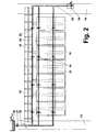
- a hose scale system of electronic tube scales 17 are formed, as shown schematically in FIG. 2 again shown with unilaterally open electronic tube scales.
- FIG. 1 is according to FIG. 2 a further hose 23 to the runners of Schildausbautechniken All three hose lines 18, 23, 24 are connected to a common supply line 25, which connects the hose lines 18, 23, 24 with the set up in the belt section 14 base station 19.
- the hose lines 18, 23, 24 are connected to the laid in the head section 13 hose line section 20, which corresponds to the training of in FIGS. 1 and 2 shown unilaterally open hose scales is guided to a set up in the head section 13 overflow basin 26.
- the filling of the tubing balance line should be done from the lowest point, ie in the case shown in the embodiment of the base station 19 from.
- a Kochlaufsiffon should be positioned with open discharge.
- the end-side last pressure sensor 21 of the measuring chain formed by the pressure sensors 22 and 21 should be integrated at a defined height under the overflow chute (overflow basin 26).
- the tubing scale system is completely filled. If a complete filling should not be given, then, for example, when an electromagnetic valve is arranged in the area of the base station 19, the automatic filling can be triggered until the desired liquid column is present in the region of the overflow basin 26.
- so-called hose pigs may be considered by means of which also air bubbles can be safely removed from a hose system.
- the advantage of using the above-described open-end tube scale initially consists in that a simple hydrostatic pressure or height determination, wherein the absolute pressures measured by the pressure sensors 22 can always be related to the pressure prevailing at the base station 19 pressure. There is no influence on the measurement due to tube crushing or temperature-induced internal pressure changes, and finally there is a low sensitivity to dynamic influences, for example in the form of mechanical vibrations. As shown, an automatic and controlled filling of the unilaterally open tube balance is possible.
- the disadvantages are that for precision measurements, a barometric correction is required. In mining operation, arrangement problems of the unilaterally open tube balance may arise because the open end of the tube scale 17 must always be at the highest point; This may require appropriate conversion measures in case of changing seam storage or changing degradation conditions. With changing overall heights, therefore, the overflow or the refilling of the hose scale must be ensured.
- precision pressure sensors should be used, with an absolute accuracy of at least 0.01 bar and a long-term stable running behavior. Compliance with an exact zero point and a very good linearity are required. Since this can only be ensured by means of an internal temperature compensation, the temperature of the liquid present in the hose line of the hose scale should also be recorded and transmitted to the evaluation and control unit, so that temperature-related changes in density of the liquid column in sections can be compensated. Also, a physical (hydraulic) and electronic damping of the measured data makes sense in order to calm the measured data despite the vibrations occurring in the extraction operation when the longwall conveyor or the passing mining machine is running.
- the pressure sensors 22 and 21 used on an electronic tube scale should be calibratable via the use of a high-precision reference sensor, wherein the reference sensor is to be connected at the same height to the respective pressure sensor.
- both sensors must be temporarily de-pressurized by suitable slide valves.
- the pressure sensor to be tested must be calibrated exactly to the zero point by setting the zero point electronically.
- the hose scale is again pushed onto the hydraulic passage, and the pressure sensor to be tested must now learn from the reference sensor the current absolute pressure.
- all the pressure sensors 22 and 21 used within the scope of the hose scale 17 receive a matching display characteristic. In this way it can be ensured that the height levels of the elements of the longwall equipment can be determined exactly even with small height differences by comparing the absolute pressures.
- air pressure influences can be laid with the hose lines 18, 23, 24 of the hose scales 17, a second small air hose to which all pressure sensors 22 and 21 are connected.
- the measurement of a differential pressure of the liquid column against the local air pressure corresponding to the ventilation conditions is possible, so that the respective influence of air pressure can be physically compensated.
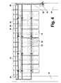
- FIGS. 1 and 2 in the Figures 3 and 4 illustrated embodiment differs from the embodiments described above in that a closed on both sides hose scale 17 is used, which is closed at its lying in the head section 13 end by means of a equipped with an open discharge pressure relief valve 29.
- This pressure relief valve 29 is used in the filling of the hose 18 from the arranged in the belt section 14 base station 19 as a discharge for air and liquid for venting and filling. If the pressure level in the closed hose system falls below a limit, an automatic refilling can take place.
- the advantage of using a double-ended electronic tube scale is that the measurements can be made independently of the altitude curve without changing the measurement setup.
- the end of the hose line 18 located in the head section 13 can now be lower than the base station 19 located in the belt section 14, without the measuring operation being disturbed.
- the difference height and the absolute height of each pressure sensor 22 at the dismounting front 10 can be determined, as described for the single-ended open-tube scale.
- the disadvantage of a tube weighing system with tube scales 17 closed on both sides is that the pressure level inside the tube scales 17 can change the pressure level due to displacements or temperature changes of the tube material, such as the liquid. Also, a higher sensitivity to dynamic influences in the form of mechanical vibrations is given, since the attenuation is reduced by the chambering of the liquid.
- FIG. 4 results, the use of multiple measuring lines in the context of a tube system with a laid on the longwall conveyor 12 hose 18 and a laid on the skids of shield removal units 15 hose 23 and with a laid on the Hangendkappen the Schildausbauismeen 15 hose 24 is possible.
- FIG. 5 The realization of such a tube weighing system in the context of a longwall equipment is again off FIG. 5 seen.
- the mining machine consists of a Walzenschrämlader 31 with cutting rollers 31 a.
- Such a structure of the longwall equipment is known in the art.
- FIG. 5 It can be seen that on longwall conveyor 12, runners 35 and Hangendkappen 32 of the shield removal units 15 hose lines 18 and 23 and 24 are laid, in the illustrated embodiment, the hose 24 is laid at the front end of the wall end caps 32.
- the roll skid loader 31 is also connected to the base station 19 via a hose line connected to it by a pressure sensor 38 arranged on the roller skid loader 31, so that the determination of the height position of the cutting roller loader 31 is likewise possible.
- tilt sensors 50 are arranged on the components of the Schildausbauticianen 15, namely hanging wall 32 and skid 35 as well as the longwall conveyor 12 and the mining machine 31, which are also used to determine height data can.
- the measured height data can be used in a variety of ways for the automated control of longwall operations.
Landscapes
- Engineering & Computer Science (AREA)
- Mining & Mineral Resources (AREA)
- Life Sciences & Earth Sciences (AREA)
- General Life Sciences & Earth Sciences (AREA)
- Geochemistry & Mineralogy (AREA)
- Geology (AREA)
- Mechanical Engineering (AREA)
- Physics & Mathematics (AREA)
- Radar, Positioning & Navigation (AREA)
- Remote Sensing (AREA)
- General Physics & Mathematics (AREA)
- Excavating Of Shafts Or Tunnels (AREA)
- Measuring Fluid Pressure (AREA)
Claims (14)
- Equipement de taille pour l'extraction mécanique par tailles chassantes à front continu, en particulier dans le domaine de l'exploitation de mines de charbon souterraines, comprenant une bande transporteuse de taille (12) disposée le long du front de taille (10), un moyen d'extraction pouvant être déplacé le long de la bande transporteuse de taille (12) et des unités de soutènement à bouclier (15) suspendues au moyen d'extraction selon un angle par rapport à la bande transporteuse de taille (12), caractérisé en ce qu'un niveau à eau (17) rempli d'un liquide est posé le long du front de taille (10) au niveau d'éléments (12, 15, 31) sélectionnés de l'équipement de taille afin de déterminer la position absolue en hauteur desdits éléments prédéfinis de l'équipement de taille, ledit niveau à eau étant raccordé à une station de base (19) dont la position en hauteur est définie avec précision comme point de référence et qui est disposé dans une des galeries conjuguées d'exploitation (13, 14), sachant que des capteurs de pression (22) sont installés, de manière répartie sur l'équipement de taille, au niveau de divers éléments (12, 15, 31) de l'équipement de taille, dans le tuyau flexible (18, 23, 24) du niveau à eau (17) et sont reliés à une unité centrale d'analyse et de commande.
- Equipement de taille selon la revendication 1, caractérisé en ce que le tuyau flexible (24) du niveau à eau (17) est posé au niveau des chapeaux de toit (32) des unités de soutènement à bouclier (15), et en ce que respectivement un capteur de pression (22) est associé à diverses unités de soutènement à bouclier (15).
- Equipement de taille selon la revendication 1, caractérisé en ce que le tuyau flexible (23) du niveau à eau (17) est posé au niveau des semelles (35) des unités de soutènement à bouclier (15), et en ce que respectivement un capteur de pression (22) est associé à diverses unités de soutènement à bouclier (15).
- Equipement de taille selon la revendication 1, caractérisé en ce que le tuyau flexible (18) du niveau à eau (17) est posé au niveau des gouttières de la bande transporteuse de taille (12), et en ce que respectivement un capteur de pression (22) est associé à divers bacs de gouttière espacés les uns des autres.
- Equipement de taille selon la revendication 1, caractérisé en ce que la machine d'extraction (31) pouvant être déplacée le long du front de taille (10) est raccordée à un tuyau flexible, raccordé à la station de base (19), du niveau à eau, et en ce qu'au moins un capteur de pression (38) est disposé au niveau de la machine d'extraction (31).
- Equipement de taille selon l'une quelconque des revendications 1 à 5, caractérisé en ce que plusieurs divers niveaux à eau (17) comprenant des tuyaux flexibles (18, 23, 24) associés et des capteurs de pression (22) disposés dans lesdits tuyaux flexibles sont disposés au niveau des éléments (12, 15, 31) de l'équipement de taille.
- Equipement de taille selon l'une quelconque des revendications 1 à 5, caractérisé en ce qu'une conduite d'arrivée (25) est guidée depuis la station de base (19) jusqu'au passage de galerie de taille (40), de laquelle conduite d'arrivée partent au moins deux tuyaux flexibles (18, 23, 24), qui sont posés au niveau de différents composants (12, 15, 31) de l'équipement de taille et qui sont reliés entre eux dans la zone de la galerie conjuguée d'exploitation opposée, et en ce que les capteurs de pression (22) installés dans les différents tuyaux flexibles (18, 23, 24) présentent respectivement la même distance du passage de galerie de taille (40).
- Equipement de taille selon l'une quelconque des revendications 1 à 7, caractérisé en ce qu'un tronçon (20) de tuyau flexible du niveau à eau (17) est posé dans la galerie conjuguée d'exploitation (13) opposée à la galerie conjuguée d'exploitation (14) logeant la station de base (19).
- Equipement de taille selon la revendication 8, caractérisé en ce qu'une soupape de limitation de pression (29) est disposée au niveau de l'extrémité du tronçon (20) de tuyau flexible pour former un niveau à eau fermé des deux côtés, rempli sous pression.
- Equipement de taille selon la revendication 8, caractérisé en ce qu'un bassin à débordement (26) formant le point le plus haut du niveau à eau (17) est disposé au niveau de l'extrémité du tronçon (20) de tuyau flexible pour former un niveau à eau ouvert d'un côté.
- Equipement de taille selon la revendication 10, caractérisé en ce que la station de base (19) est disposée dans la galerie conjuguée d'exploitation (14) située respectivement au point le plus bas.
- Equipement de taille selon la revendication 10 ou 11, caractérisé en ce que le capteur de pression (21), se trouvant immédiatement à proximité du bassin à débordement (26), du niveau à eau (17) est disposé à une hauteur définie sous le bassin à débordement (26).
- Equipement de taille selon l'une quelconque des revendications 1 à 12, caractérisé en ce qu'un raccord servant à remplir de liquide le niveau à eau (17) est disposé au niveau de la station de base (19).
- Equipement de taille selon l'une quelconque des revendications 1 à 10, caractérisé en ce qu'est posé, de manière parallèle au tuyau flexible (18, 23, 24) du niveau à eau (17), un tuyau d'air, auquel sont raccordés les capteurs de pression (22) disposés dans le tuyau flexible du niveau à eau.
Priority Applications (1)
| Application Number | Priority Date | Filing Date | Title |
|---|---|---|---|
| PL10801385T PL2659092T3 (pl) | 2010-12-30 | 2010-12-30 | Wyposażenie ściany z usytuowaną na nim poziomicą wężową do określania położenia wysokości poszczególnych elementów tego wyposażenia ściany |
Applications Claiming Priority (1)
| Application Number | Priority Date | Filing Date | Title |
|---|---|---|---|
| PCT/EP2010/007991 WO2012089230A1 (fr) | 2010-12-30 | 2010-12-30 | Équipement de taille comprenant un niveau à eau posé dessus pour déterminer la position en hauteur d'éléments individuels de l'équipement de taille |
Publications (2)
| Publication Number | Publication Date |
|---|---|
| EP2659092A1 EP2659092A1 (fr) | 2013-11-06 |
| EP2659092B1 true EP2659092B1 (fr) | 2014-09-24 |
Family
ID=44314185
Family Applications (1)
| Application Number | Title | Priority Date | Filing Date |
|---|---|---|---|
| EP10801385.5A Not-in-force EP2659092B1 (fr) | 2010-12-30 | 2010-12-30 | Equipement de transporteur en taille muni d'un dispositif de mesure de nivellement utilisant un tuyau afin de déterminer la hauteur d'éléments individuels du transporteur de taille |
Country Status (8)
| Country | Link |
|---|---|
| US (1) | US9227792B2 (fr) |
| EP (1) | EP2659092B1 (fr) |
| CN (1) | CN103459772B (fr) |
| AU (1) | AU2010366615B2 (fr) |
| PL (1) | PL2659092T3 (fr) |
| RU (1) | RU2544939C2 (fr) |
| UA (1) | UA105600C2 (fr) |
| WO (1) | WO2012089230A1 (fr) |
Families Citing this family (15)
| Publication number | Priority date | Publication date | Assignee | Title |
|---|---|---|---|---|
| UA109514C2 (uk) * | 2012-04-02 | 2015-08-25 | Забійне обладнання з покладеними між забійним конвеєром і каркасами щитового кріплення шланговими нівелірами | |
| CN103114867B (zh) * | 2013-02-22 | 2015-07-22 | 广州日滨科技发展有限公司 | 综采工作面液压支架和刮板输送机自动调直方法及系统 |
| CN104132640B (zh) * | 2014-08-18 | 2017-02-15 | 中国地质调查局水文地质环境地质调查中心 | 地面沉降分层原位监测装置及监测方法 |
| CN105737791A (zh) * | 2014-12-12 | 2016-07-06 | 四川省科建煤炭产业技术研究院有限公司 | 一种大倾角综采工作面液压支架位姿检测方法 |
| CN104912581B (zh) * | 2015-05-08 | 2017-06-13 | 广州日滨科技发展有限公司 | 液压支架数据采集方法和系统、液压支架集控系统 |
| CN105240013B (zh) | 2015-06-24 | 2017-12-15 | 何满潮 | 长壁开采n00工法 |
| CN106168131B (zh) * | 2015-06-24 | 2018-05-18 | 北京中矿创新联盟能源环境科学研究院 | 无巷道无煤柱自留巷开采工法的装备系统 |
| WO2016206616A1 (fr) * | 2015-06-24 | 2016-12-29 | 何满潮 | Système d'équipement pour procédé d'exploitation minière de voie retenue sans pilier en charbon sans voie |
| CN105858256A (zh) * | 2016-06-07 | 2016-08-17 | 刘丹 | 一种矿用多功能运输装置 |
| GB2581983B (en) * | 2019-03-06 | 2021-07-21 | Caterpillar Global Mining Gmbh | Method and device for monitoring operation of a mining machine unit |
| CN110909976B (zh) * | 2019-10-11 | 2023-05-12 | 重庆大学 | 一种突出矿井抽掘采部署合理性评判改进方法及装置 |
| CN112879097B (zh) * | 2021-04-09 | 2022-06-24 | 郑州煤机液压电控有限公司 | 采煤工作面运输机上窜或下滑自动检测方法 |
| CN113088431A (zh) * | 2021-04-28 | 2021-07-09 | 贵州同辉食用菌发展有限公司 | 一种高活性、高稳定性香菇液体菌种发酵系统及发酵方法 |
| CN113323698B (zh) * | 2021-05-31 | 2023-11-03 | 国能神东煤炭集团有限责任公司 | 综采工作面推进距离计算方法、存储介质及电子设备 |
| CN120007333B (zh) * | 2024-12-25 | 2025-10-28 | 中国矿业大学 | 一种充填面多孔底卸式刮板输送机平直度控制方法 |
Family Cites Families (10)
| Publication number | Priority date | Publication date | Assignee | Title |
|---|---|---|---|---|
| US4218919A (en) * | 1978-09-08 | 1980-08-26 | Stephenson Donald K | Apparatus for measuring elevation |
| DE2944305C2 (de) * | 1979-11-02 | 1983-01-27 | Hochtief Ag Vorm. Gebr. Helfmann, 4300 Essen | Steuerleitgerät für eine Tunnelvortriebsmaschine |
| US4356639A (en) * | 1980-08-08 | 1982-11-02 | Jorge Alarcon Opazo | Compact portable digital multimeter for instantaneous measuring of height differences independently of visibility |
| US4397099A (en) * | 1981-09-08 | 1983-08-09 | Edwin Gaucher | Electronic apparatus for measuring the difference of elevation between two points |
| FR2638830B1 (fr) * | 1988-11-10 | 1993-01-29 | Inst Francais Du Petrole | Dispositif pour determiner la distance verticale entre deux elements a des hauteurs inegales |
| DE4333032C2 (de) * | 1993-09-29 | 1996-11-28 | Honeywell Ag | Vorrichtung zur Bestimmung der Position, Lage und Ausrichtung einer Tunnelvortriebsmaschine |
| ATE348940T1 (de) * | 2000-04-26 | 2007-01-15 | Commw Scient Ind Res Org | Bergbaumaschine und abbauverfahren |
| CN101418688B (zh) * | 2007-10-26 | 2011-09-07 | 三一重型装备有限公司 | 智能型全自动联合采煤系统 |
| CN101970795B (zh) * | 2008-02-19 | 2013-06-12 | 拉格股份公司 | 控制长壁开采作业的方法 |
| DE102009026011A1 (de) * | 2009-06-23 | 2010-12-30 | Bucyrus Europe Gmbh | Verfahren zur Bestimmung der Position oder Lage von Anlagekomponenten in Bergbau-Gewinnungsanlagen und Gewinnungsanlage |
-
2010
- 2010-12-30 CN CN201080071266.5A patent/CN103459772B/zh not_active Expired - Fee Related
- 2010-12-30 UA UAA201308076A patent/UA105600C2/uk unknown
- 2010-12-30 EP EP10801385.5A patent/EP2659092B1/fr not_active Not-in-force
- 2010-12-30 US US13/977,587 patent/US9227792B2/en not_active Expired - Fee Related
- 2010-12-30 WO PCT/EP2010/007991 patent/WO2012089230A1/fr not_active Ceased
- 2010-12-30 PL PL10801385T patent/PL2659092T3/pl unknown
- 2010-12-30 RU RU2013129695/03A patent/RU2544939C2/ru not_active IP Right Cessation
- 2010-12-30 AU AU2010366615A patent/AU2010366615B2/en not_active Ceased
Also Published As
| Publication number | Publication date |
|---|---|
| RU2544939C2 (ru) | 2015-03-20 |
| PL2659092T3 (pl) | 2015-03-31 |
| RU2013129695A (ru) | 2015-01-10 |
| AU2010366615A1 (en) | 2013-07-11 |
| CN103459772A (zh) | 2013-12-18 |
| CN103459772B (zh) | 2015-06-17 |
| EP2659092A1 (fr) | 2013-11-06 |
| WO2012089230A1 (fr) | 2012-07-05 |
| AU2010366615B2 (en) | 2015-11-26 |
| US9227792B2 (en) | 2016-01-05 |
| UA105600C2 (uk) | 2014-05-26 |
| US20140097067A1 (en) | 2014-04-10 |
Similar Documents
| Publication | Publication Date | Title |
|---|---|---|
| WO2012089230A1 (fr) | Équipement de taille comprenant un niveau à eau posé dessus pour déterminer la position en hauteur d'éléments individuels de l'équipement de taille | |
| EP2247823B1 (fr) | Procédé pour assurer la commande d'installations d'exploitation par taille | |
| DE102009030130B9 (de) | Verfahren zur automatisierten Herstellung einer definierten Streböffnung durch neigungsgestützte Radarnavigation der Walze bei einem Walzenschrämlader und eine Vorrichtung hierfür | |
| DE3120010C2 (fr) | ||
| WO2009103306A1 (fr) | Procede pour stabiliser la colonne de soutenement a bouclier dans une installation d'exploitation par taille guidee dans l'inclinaison de filons | |
| DE102009026011A1 (de) | Verfahren zur Bestimmung der Position oder Lage von Anlagekomponenten in Bergbau-Gewinnungsanlagen und Gewinnungsanlage | |
| WO2010020359A1 (fr) | Procédé pour la détermination de la position et de la situation d'excavations souterraines et/ou d'équipements par utilisation de la technique rfid | |
| DE102007035848C5 (de) | Ausbauschild und Verfahren zur Steuerung oder Positionsbestimmung eines Ausbauschildes | |
| DE102014005077A1 (de) | Selbstfahrende Baumaschine und Verfahren zum Steuern einer selbstfahrenden Baumaschine | |
| WO2016134690A9 (fr) | Procédé pour le fonctionnement d'une machine d'enlèvement destinée à l'enlèvement du charbon dans la taille souterraine d'une mine de charbon | |
| EP2834464B1 (fr) | Équipement de taille muni de niveaux à eau posés sur ses éléments de soutènement bouclier | |
| DE4017833C1 (fr) | ||
| DE4333032C2 (de) | Vorrichtung zur Bestimmung der Position, Lage und Ausrichtung einer Tunnelvortriebsmaschine | |
| EP3670747B1 (fr) | Engin de construction autonome et procédé d'usinage d'un revêtement de sol | |
| DE4439601C2 (de) | Verfahren zur Richtungssteuerung einer im Untertagebetrieb eingesetzten Maschine sowie zur Durchführung des Verfahrens geeignete Maschine | |
| EP2834465B1 (fr) | Équipement de taille muni de niveaux à eau posés entre un convoyeur de taille et des éléments de soutènement bouclier | |
| DE10346890B4 (de) | Verfahren und Anordnung zur kontinuierlichen Erfassung von Setzungen an Bauwerken mittels hydrostatischem Schlauchwaagenmeßsystem | |
| DE3034704A1 (de) | Schienenfahrzeug fuer gleiskoerperarbeiten | |
| DE2525698A1 (de) | Anordnung zum ermitteln, einstellen und/oder speichern einer richtung | |
| DE3424248C2 (fr) | ||
| DE102007012678B3 (de) | Verfahren zum Steuern von Strebbetrieben im untertägigen Steinkohlenbergbau | |
| EP1197730B1 (fr) | Procédé pour déterminer des profils longitudinaux et dispositif pour mettre en oeuvre le procédé | |
| DE102017110743B4 (de) | Verfahren zum Ausrichten eines Strebausbaus sowie Anordnung zur Bestimmung der Position von Schreitausbauen eines Strebausbaus | |
| EP1577640B1 (fr) | Procédé et dispositif de mesure hydrostatique de hauteur | |
| DE19507346C2 (de) | Verfahren zum Steuern einer Vortriebsmaschine bei der Herstellung eines unterirdischen Hohlraumprofils sowie Einrichtung zur Durchführung des Verfahrens |
Legal Events
| Date | Code | Title | Description |
|---|---|---|---|
| PUAI | Public reference made under article 153(3) epc to a published international application that has entered the european phase |
Free format text: ORIGINAL CODE: 0009012 |
|
| 17P | Request for examination filed |
Effective date: 20130628 |
|
| AK | Designated contracting states |
Kind code of ref document: A1 Designated state(s): AL AT BE BG CH CY CZ DE DK EE ES FI FR GB GR HR HU IE IS IT LI LT LU LV MC MK MT NL NO PL PT RO RS SE SI SK SM TR |
|
| DAX | Request for extension of the european patent (deleted) | ||
| REG | Reference to a national code |
Ref country code: DE Ref legal event code: R079 Ref document number: 502010007962 Country of ref document: DE Free format text: PREVIOUS MAIN CLASS: E21D0023000000 Ipc: E21D0023120000 |
|
| GRAP | Despatch of communication of intention to grant a patent |
Free format text: ORIGINAL CODE: EPIDOSNIGR1 |
|
| RIC1 | Information provided on ipc code assigned before grant |
Ipc: G01C 5/04 20060101ALI20140429BHEP Ipc: B65G 43/00 20060101ALI20140429BHEP Ipc: E21D 23/00 20060101ALI20140429BHEP Ipc: E21D 23/12 20060101AFI20140429BHEP |
|
| INTG | Intention to grant announced |
Effective date: 20140523 |
|
| GRAS | Grant fee paid |
Free format text: ORIGINAL CODE: EPIDOSNIGR3 |
|
| GRAA | (expected) grant |
Free format text: ORIGINAL CODE: 0009210 |
|
| AK | Designated contracting states |
Kind code of ref document: B1 Designated state(s): AL AT BE BG CH CY CZ DE DK EE ES FI FR GB GR HR HU IE IS IT LI LT LU LV MC MK MT NL NO PL PT RO RS SE SI SK SM TR |
|
| REG | Reference to a national code |
Ref country code: GB Ref legal event code: FG4D Free format text: NOT ENGLISH |
|
| REG | Reference to a national code |
Ref country code: CH Ref legal event code: EP |
|
| REG | Reference to a national code |
Ref country code: AT Ref legal event code: REF Ref document number: 688749 Country of ref document: AT Kind code of ref document: T Effective date: 20141015 |
|
| REG | Reference to a national code |
Ref country code: IE Ref legal event code: FG4D Free format text: LANGUAGE OF EP DOCUMENT: GERMAN |
|
| REG | Reference to a national code |
Ref country code: DE Ref legal event code: R096 Ref document number: 502010007962 Country of ref document: DE Effective date: 20141106 |
|
| PG25 | Lapsed in a contracting state [announced via postgrant information from national office to epo] |
Ref country code: FI Free format text: LAPSE BECAUSE OF FAILURE TO SUBMIT A TRANSLATION OF THE DESCRIPTION OR TO PAY THE FEE WITHIN THE PRESCRIBED TIME-LIMIT Effective date: 20140924 Ref country code: GR Free format text: LAPSE BECAUSE OF FAILURE TO SUBMIT A TRANSLATION OF THE DESCRIPTION OR TO PAY THE FEE WITHIN THE PRESCRIBED TIME-LIMIT Effective date: 20141225 Ref country code: SE Free format text: LAPSE BECAUSE OF FAILURE TO SUBMIT A TRANSLATION OF THE DESCRIPTION OR TO PAY THE FEE WITHIN THE PRESCRIBED TIME-LIMIT Effective date: 20140924 Ref country code: LT Free format text: LAPSE BECAUSE OF FAILURE TO SUBMIT A TRANSLATION OF THE DESCRIPTION OR TO PAY THE FEE WITHIN THE PRESCRIBED TIME-LIMIT Effective date: 20140924 Ref country code: NO Free format text: LAPSE BECAUSE OF FAILURE TO SUBMIT A TRANSLATION OF THE DESCRIPTION OR TO PAY THE FEE WITHIN THE PRESCRIBED TIME-LIMIT Effective date: 20141224 |
|
| PGFP | Annual fee paid to national office [announced via postgrant information from national office to epo] |
Ref country code: TR Payment date: 20141113 Year of fee payment: 5 |
|
| REG | Reference to a national code |
Ref country code: LT Ref legal event code: MG4D Ref country code: NL Ref legal event code: VDEP Effective date: 20140924 |
|
| PG25 | Lapsed in a contracting state [announced via postgrant information from national office to epo] |
Ref country code: RS Free format text: LAPSE BECAUSE OF FAILURE TO SUBMIT A TRANSLATION OF THE DESCRIPTION OR TO PAY THE FEE WITHIN THE PRESCRIBED TIME-LIMIT Effective date: 20140924 Ref country code: LV Free format text: LAPSE BECAUSE OF FAILURE TO SUBMIT A TRANSLATION OF THE DESCRIPTION OR TO PAY THE FEE WITHIN THE PRESCRIBED TIME-LIMIT Effective date: 20140924 Ref country code: HR Free format text: LAPSE BECAUSE OF FAILURE TO SUBMIT A TRANSLATION OF THE DESCRIPTION OR TO PAY THE FEE WITHIN THE PRESCRIBED TIME-LIMIT Effective date: 20140924 Ref country code: CY Free format text: LAPSE BECAUSE OF FAILURE TO SUBMIT A TRANSLATION OF THE DESCRIPTION OR TO PAY THE FEE WITHIN THE PRESCRIBED TIME-LIMIT Effective date: 20140924 |
|
| PG25 | Lapsed in a contracting state [announced via postgrant information from national office to epo] |
Ref country code: NL Free format text: LAPSE BECAUSE OF FAILURE TO SUBMIT A TRANSLATION OF THE DESCRIPTION OR TO PAY THE FEE WITHIN THE PRESCRIBED TIME-LIMIT Effective date: 20140924 |
|
| REG | Reference to a national code |
Ref country code: PL Ref legal event code: T3 |
|
| PG25 | Lapsed in a contracting state [announced via postgrant information from national office to epo] |
Ref country code: IS Free format text: LAPSE BECAUSE OF FAILURE TO SUBMIT A TRANSLATION OF THE DESCRIPTION OR TO PAY THE FEE WITHIN THE PRESCRIBED TIME-LIMIT Effective date: 20150124 Ref country code: RO Free format text: LAPSE BECAUSE OF FAILURE TO SUBMIT A TRANSLATION OF THE DESCRIPTION OR TO PAY THE FEE WITHIN THE PRESCRIBED TIME-LIMIT Effective date: 20140924 Ref country code: SK Free format text: LAPSE BECAUSE OF FAILURE TO SUBMIT A TRANSLATION OF THE DESCRIPTION OR TO PAY THE FEE WITHIN THE PRESCRIBED TIME-LIMIT Effective date: 20140924 Ref country code: PT Free format text: LAPSE BECAUSE OF FAILURE TO SUBMIT A TRANSLATION OF THE DESCRIPTION OR TO PAY THE FEE WITHIN THE PRESCRIBED TIME-LIMIT Effective date: 20150126 Ref country code: ES Free format text: LAPSE BECAUSE OF FAILURE TO SUBMIT A TRANSLATION OF THE DESCRIPTION OR TO PAY THE FEE WITHIN THE PRESCRIBED TIME-LIMIT Effective date: 20140924 Ref country code: EE Free format text: LAPSE BECAUSE OF FAILURE TO SUBMIT A TRANSLATION OF THE DESCRIPTION OR TO PAY THE FEE WITHIN THE PRESCRIBED TIME-LIMIT Effective date: 20140924 |
|
| REG | Reference to a national code |
Ref country code: DE Ref legal event code: R097 Ref document number: 502010007962 Country of ref document: DE |
|
| PG25 | Lapsed in a contracting state [announced via postgrant information from national office to epo] |
Ref country code: BE Free format text: LAPSE BECAUSE OF NON-PAYMENT OF DUE FEES Effective date: 20141231 |
|
| PG25 | Lapsed in a contracting state [announced via postgrant information from national office to epo] |
Ref country code: LU Free format text: LAPSE BECAUSE OF FAILURE TO SUBMIT A TRANSLATION OF THE DESCRIPTION OR TO PAY THE FEE WITHIN THE PRESCRIBED TIME-LIMIT Effective date: 20141230 Ref country code: DK Free format text: LAPSE BECAUSE OF FAILURE TO SUBMIT A TRANSLATION OF THE DESCRIPTION OR TO PAY THE FEE WITHIN THE PRESCRIBED TIME-LIMIT Effective date: 20140924 |
|
| PLBE | No opposition filed within time limit |
Free format text: ORIGINAL CODE: 0009261 |
|
| REG | Reference to a national code |
Ref country code: CH Ref legal event code: PL |
|
| STAA | Information on the status of an ep patent application or granted ep patent |
Free format text: STATUS: NO OPPOSITION FILED WITHIN TIME LIMIT |
|
| GBPC | Gb: european patent ceased through non-payment of renewal fee |
Effective date: 20141230 |
|
| PG25 | Lapsed in a contracting state [announced via postgrant information from national office to epo] |
Ref country code: IT Free format text: LAPSE BECAUSE OF FAILURE TO SUBMIT A TRANSLATION OF THE DESCRIPTION OR TO PAY THE FEE WITHIN THE PRESCRIBED TIME-LIMIT Effective date: 20140924 |
|
| 26N | No opposition filed |
Effective date: 20150625 |
|
| REG | Reference to a national code |
Ref country code: IE Ref legal event code: MM4A |
|
| REG | Reference to a national code |
Ref country code: FR Ref legal event code: ST Effective date: 20150831 |
|
| PG25 | Lapsed in a contracting state [announced via postgrant information from national office to epo] |
Ref country code: IE Free format text: LAPSE BECAUSE OF NON-PAYMENT OF DUE FEES Effective date: 20141230 Ref country code: CH Free format text: LAPSE BECAUSE OF NON-PAYMENT OF DUE FEES Effective date: 20141231 Ref country code: LI Free format text: LAPSE BECAUSE OF NON-PAYMENT OF DUE FEES Effective date: 20141231 Ref country code: GB Free format text: LAPSE BECAUSE OF NON-PAYMENT OF DUE FEES Effective date: 20141230 |
|
| PG25 | Lapsed in a contracting state [announced via postgrant information from national office to epo] |
Ref country code: FR Free format text: LAPSE BECAUSE OF NON-PAYMENT OF DUE FEES Effective date: 20141231 |
|
| PG25 | Lapsed in a contracting state [announced via postgrant information from national office to epo] |
Ref country code: SI Free format text: LAPSE BECAUSE OF FAILURE TO SUBMIT A TRANSLATION OF THE DESCRIPTION OR TO PAY THE FEE WITHIN THE PRESCRIBED TIME-LIMIT Effective date: 20140924 |
|
| PG25 | Lapsed in a contracting state [announced via postgrant information from national office to epo] |
Ref country code: SM Free format text: LAPSE BECAUSE OF FAILURE TO SUBMIT A TRANSLATION OF THE DESCRIPTION OR TO PAY THE FEE WITHIN THE PRESCRIBED TIME-LIMIT Effective date: 20140924 |
|
| PG25 | Lapsed in a contracting state [announced via postgrant information from national office to epo] |
Ref country code: MC Free format text: LAPSE BECAUSE OF FAILURE TO SUBMIT A TRANSLATION OF THE DESCRIPTION OR TO PAY THE FEE WITHIN THE PRESCRIBED TIME-LIMIT Effective date: 20140924 |
|
| PG25 | Lapsed in a contracting state [announced via postgrant information from national office to epo] |
Ref country code: BG Free format text: LAPSE BECAUSE OF FAILURE TO SUBMIT A TRANSLATION OF THE DESCRIPTION OR TO PAY THE FEE WITHIN THE PRESCRIBED TIME-LIMIT Effective date: 20140924 |
|
| PG25 | Lapsed in a contracting state [announced via postgrant information from national office to epo] |
Ref country code: MT Free format text: LAPSE BECAUSE OF FAILURE TO SUBMIT A TRANSLATION OF THE DESCRIPTION OR TO PAY THE FEE WITHIN THE PRESCRIBED TIME-LIMIT Effective date: 20140924 Ref country code: HU Free format text: LAPSE BECAUSE OF FAILURE TO SUBMIT A TRANSLATION OF THE DESCRIPTION OR TO PAY THE FEE WITHIN THE PRESCRIBED TIME-LIMIT; INVALID AB INITIO Effective date: 20101230 |
|
| PGFP | Annual fee paid to national office [announced via postgrant information from national office to epo] |
Ref country code: CZ Payment date: 20161123 Year of fee payment: 7 |
|
| REG | Reference to a national code |
Ref country code: AT Ref legal event code: MM01 Ref document number: 688749 Country of ref document: AT Kind code of ref document: T Effective date: 20151230 |
|
| PGFP | Annual fee paid to national office [announced via postgrant information from national office to epo] |
Ref country code: PL Payment date: 20161124 Year of fee payment: 7 |
|
| PG25 | Lapsed in a contracting state [announced via postgrant information from national office to epo] |
Ref country code: AT Free format text: LAPSE BECAUSE OF NON-PAYMENT OF DUE FEES Effective date: 20151230 |
|
| PG25 | Lapsed in a contracting state [announced via postgrant information from national office to epo] |
Ref country code: MK Free format text: LAPSE BECAUSE OF FAILURE TO SUBMIT A TRANSLATION OF THE DESCRIPTION OR TO PAY THE FEE WITHIN THE PRESCRIBED TIME-LIMIT Effective date: 20140924 |
|
| PG25 | Lapsed in a contracting state [announced via postgrant information from national office to epo] |
Ref country code: AL Free format text: LAPSE BECAUSE OF FAILURE TO SUBMIT A TRANSLATION OF THE DESCRIPTION OR TO PAY THE FEE WITHIN THE PRESCRIBED TIME-LIMIT Effective date: 20140924 |
|
| PG25 | Lapsed in a contracting state [announced via postgrant information from national office to epo] |
Ref country code: CZ Free format text: LAPSE BECAUSE OF NON-PAYMENT OF DUE FEES Effective date: 20171230 |
|
| PG25 | Lapsed in a contracting state [announced via postgrant information from national office to epo] |
Ref country code: PL Free format text: LAPSE BECAUSE OF NON-PAYMENT OF DUE FEES Effective date: 20171230 |
|
| PGFP | Annual fee paid to national office [announced via postgrant information from national office to epo] |
Ref country code: DE Payment date: 20200228 Year of fee payment: 10 |
|
| REG | Reference to a national code |
Ref country code: DE Ref legal event code: R119 Ref document number: 502010007962 Country of ref document: DE |
|
| PG25 | Lapsed in a contracting state [announced via postgrant information from national office to epo] |
Ref country code: DE Free format text: LAPSE BECAUSE OF NON-PAYMENT OF DUE FEES Effective date: 20210701 |
|
| PG25 | Lapsed in a contracting state [announced via postgrant information from national office to epo] |
Ref country code: TR Free format text: LAPSE BECAUSE OF NON-PAYMENT OF DUE FEES Effective date: 20171230 |