EP2247823B1 - Procédé pour assurer la commande d'installations d'exploitation par taille - Google Patents
Procédé pour assurer la commande d'installations d'exploitation par taille Download PDFInfo
- Publication number
- EP2247823B1 EP2247823B1 EP08715851.5A EP08715851A EP2247823B1 EP 2247823 B1 EP2247823 B1 EP 2247823B1 EP 08715851 A EP08715851 A EP 08715851A EP 2247823 B1 EP2247823 B1 EP 2247823B1
- Authority
- EP
- European Patent Office
- Prior art keywords
- shield
- support frame
- shield support
- inclination
- top canopy
- Prior art date
- Legal status (The legal status is an assumption and is not a legal conclusion. Google has not performed a legal analysis and makes no representation as to the accuracy of the status listed.)
- Not-in-force
Links
- 238000000034 method Methods 0.000 title claims description 35
- 238000005065 mining Methods 0.000 title claims description 29
- 238000000605 extraction Methods 0.000 claims description 16
- 230000001133 acceleration Effects 0.000 claims description 7
- 238000005452 bending Methods 0.000 claims description 5
- 239000003245 coal Substances 0.000 claims description 4
- 230000007246 mechanism Effects 0.000 claims description 3
- 238000013016 damping Methods 0.000 claims description 2
- 230000001419 dependent effect Effects 0.000 claims description 2
- 238000010521 absorption reaction Methods 0.000 claims 1
- 230000005484 gravity Effects 0.000 claims 1
- 239000011435 rock Substances 0.000 claims 1
- 238000001514 detection method Methods 0.000 description 7
- 230000008859 change Effects 0.000 description 5
- 238000010276 construction Methods 0.000 description 5
- 206010019133 Hangover Diseases 0.000 description 3
- 230000008901 benefit Effects 0.000 description 3
- 238000012937 correction Methods 0.000 description 3
- 238000011156 evaluation Methods 0.000 description 3
- 238000005259 measurement Methods 0.000 description 3
- 230000008569 process Effects 0.000 description 3
- 238000011084 recovery Methods 0.000 description 3
- 229910000831 Steel Inorganic materials 0.000 description 2
- 238000013459 approach Methods 0.000 description 2
- 230000009194 climbing Effects 0.000 description 2
- 238000013461 design Methods 0.000 description 2
- 238000011161 development Methods 0.000 description 2
- 230000018109 developmental process Effects 0.000 description 2
- 230000000694 effects Effects 0.000 description 2
- 238000012544 monitoring process Methods 0.000 description 2
- 238000010008 shearing Methods 0.000 description 2
- 239000010959 steel Substances 0.000 description 2
- 230000002123 temporal effect Effects 0.000 description 2
- 241000406668 Loxodonta cyclotis Species 0.000 description 1
- 235000014676 Phragmites communis Nutrition 0.000 description 1
- 238000009825 accumulation Methods 0.000 description 1
- 230000004913 activation Effects 0.000 description 1
- 230000000052 comparative effect Effects 0.000 description 1
- 230000009189 diving Effects 0.000 description 1
- 230000006870 function Effects 0.000 description 1
- 239000011440 grout Substances 0.000 description 1
- 230000000977 initiatory effect Effects 0.000 description 1
- 238000009434 installation Methods 0.000 description 1
- 230000007257 malfunction Effects 0.000 description 1
- 238000005457 optimization Methods 0.000 description 1
- 230000035515 penetration Effects 0.000 description 1
- 238000004886 process control Methods 0.000 description 1
- 230000000284 resting effect Effects 0.000 description 1
- 230000000630 rising effect Effects 0.000 description 1
- 238000004826 seaming Methods 0.000 description 1
- 230000001953 sensory effect Effects 0.000 description 1
- 238000000926 separation method Methods 0.000 description 1
- 239000007787 solid Substances 0.000 description 1
Images



Classifications
-
- E—FIXED CONSTRUCTIONS
- E21—EARTH OR ROCK DRILLING; MINING
- E21D—SHAFTS; TUNNELS; GALLERIES; LARGE UNDERGROUND CHAMBERS
- E21D23/00—Mine roof supports for step- by- step movement, e.g. in combination with provisions for shifting of conveyors, mining machines, or guides therefor
- E21D23/12—Control, e.g. using remote control
-
- E—FIXED CONSTRUCTIONS
- E21—EARTH OR ROCK DRILLING; MINING
- E21C—MINING OR QUARRYING
- E21C35/00—Details of, or accessories for, machines for slitting or completely freeing the mineral from the seam, not provided for in groups E21C25/00 - E21C33/00, E21C37/00 or E21C39/00
- E21C35/282—Autonomous machines; Autonomous operations
-
- E—FIXED CONSTRUCTIONS
- E21—EARTH OR ROCK DRILLING; MINING
- E21C—MINING OR QUARRYING
- E21C35/00—Details of, or accessories for, machines for slitting or completely freeing the mineral from the seam, not provided for in groups E21C25/00 - E21C33/00, E21C37/00 or E21C39/00
- E21C35/302—Measuring, signaling or indicating specially adapted for machines for slitting or completely freeing the mineral
Definitions
- the invention relates to a method for controlling a longwall conveyor, at least one mining machine and a hydraulic shield removal having longwall mining operations in underground coal mining.
- a method of the aforementioned type is in the DE 196 36 389 A1 described, in which a load control of the shield removal point is provided, in which the critical load cases "unilateral load” and / or “peak dance” detected during the setting process using appropriate sensors and rendered harmless by appropriate control of the hydraulic punch and / or a corner cylinder in their impact become.
- sensors are arranged on the components of the shield-mounting frame whose electrical measured values are used by a control unit for evaluating the measuring signals and for controlling the hydraulic punches and / or the corner cylinder assigned to the shield-mounting frame.
- Controlling struts during pillage is generally about making the best possible use of the resources provided Machine capacities while avoiding stoppages, where possible, an automation of the necessary control operations should be given to avoid erroneous human decisions.
- Approaches to automation of the controller are in development or already in use, such as sensory boundary layer detection / control, learning step method, detection and control of the way back of the walking structure, automated pacing of the walking structure and automatic compliance with a predetermined nominal inclination of the longwall conveyor.
- the invention is therefore based on the object to show a method of the type mentioned above, which gives indications of a possible collision between the mining machine and the shield support frame and thereby helps to avoid corresponding collisions.
- the invention provides a method in which inclination sensors mounted on at least three of the four main components of each shield support structure such as bottom skid, breaker shield, support links, and fractured section of the hangum cap determine the inclination of the shield components against the horizontal in the direction of travel and from the measured data in a computing unit by comparison with the stored therein, the geometric orientation of the components and their movement during walking defining basic data, the respective banking rights height of the shield support frame is calculated at the front end of the hanging wall as a measure of the longwall.
- the invention initially has the advantage that solely due to the geometrical conditions to be determined with a comparatively low outlay when using the shield extension, the front end of the hanging wall can be determined in the form of the bank-legal height determined for this point; as long as this Strebö réelle the produced by the mining machine during their scheduled operation Strebö réelle corresponds or is slightly larger, there is no risk of a collision of the mining machine with the relevant Schildausbaugestellen. If the constant monitoring of the longwall opening at the front end of the hang-end cap results in a too small bracing opening, an impending collision can be counteracted by a corresponding activation of the mining machine.
- the data obtained at individual shield extension points provide additional information about the behavior of individual sections of the front panel or the entire front panel as the penetration progresses, which enables integral process control of the respective mining operation.
- Adjustment limit of the shield extension in a targeted automatic operation threatens.
- the danger of a landing of the hanging wall then exists when entering the convergence of the shield temples are completely retracted and due to the then overburdening wall hanging the shield expansion block is blocked and can not be brought forward;
- Another possibility is that the steel construction at the lower Verstellalia in Lemniskatengetriebe the shield support frame or in the joint hanging end cap / rupture shield blocked and then can not be brought forward.
- the above moments of danger apply in particular to the passage of saddles or depressions in the course of the seam, which can be accommodated by a corresponding device of the recovery height of the respective recovery machine used.
- the corresponding face opening data can provide information about a possible fall from the hanging, the occurrence of seaming, the "on-coal driving" give the mining machine or a possible lying incision of the mining machine.
- Schildausbaugestelle be used in a design with divided Bodenkufe in which between the two single skids the walking mechanism of Schildbausbaestestells is arranged so that the two individual runners of Schildschild rack are in contrast to interconnected runners segregated from each other separately can, whereby the so-called Elephant Step is possible as a step control.
- the so-called Elephant Step is possible as a step control.
- Shield extension points on each individual skids one inclination sensor is arranged.
- the respective height of the shield is calculated from the measured angles of inclination for the hangover cap, the breaker plate and for the right and left individual skids of the shield support frame, it being possible to provide that the height of the shield determined for the shield support frame the mean value of the height values calculated for the two individual skids is calculated.
- a single evaluation of the height of the sign is required for the right and left half of the sign based on the inclination angle determined on the single runners.
- the inclination sensors attached to the shield components are placed at locations with a minimum bending angle of the components, this serves to minimize measurement errors under load.
- the stamp of the walking frame is determined by means of pressure sensors of the internal stamp pressure.
- a correction factor taking into account the bending load in practical use of the longwall support station can be used as a function of the respective load recorded during operation, as provided according to an exemplary embodiment of the invention.
- the inclination of the hanging end cap against the horizontal, transverse to the direction of travel is ascertained via the inclination sensor attached to the hanging end cap of the shielding structure.
- the screwing height of the hanging end cap may be reduced, or the hanging end cap in the dressing may be aligned with adjacent shild support points prior to the shearing cycle, or the shearing cycle may be discontinued prior to re-setting the shingling frame concerned if that shim assembly has fallen out of the association; then there is also a correction.
- the determined for a shield frame position associated with the extraction machine roller cutting height is assigned by means of a location-synchronous evaluation of the temporal expansion delay of the hanging wall of the associated shield expansion rack determined for this position Strebö réelle.
- expansion delay the fact is taken into account that the Strebö réelle made by the mining machine is reached from the top of the hanging end cap of the associated shield support frame until one or two expansion steps later, which is referred to as expansion delay.
- the height data can be used at one and the same location.
- historical cutting height data are set in the mentioned arithmetic unit and set in the comparison with the shield data at the same spatial coordinate as soon as the shield expansion frame has reached the corresponding spatial coordinate. This procedure can also be referred to as location-synchronous evaluation.
- the control method according to the invention is further improved by determining the inclination of the conveyor and / or mining machine against the horizontal in the direction of travel of the shield extension by means of inclination sensors attached to the conveyor and / or mining machine.
- the arrangement of an inclination sensor on the mining machine is sufficient.
- the mining machine carried on and guided by the walkway conveyor is, so to speak, integral with the longwall conveyor, to improve the accuracy of the control, it may be convenient to also detect the slope of the longwall conveyor via a tilt sensor disposed thereon.
- the arrangement of an inclination sensor only on the longwall conveyor for the purpose of the control also sufficient.
- the angle of inclination of conveyor and / or mining machine set in relation to the determined at the bottom of the skid frame and / or Hangendkappe tilt angle and the differential angle formed in the calculation of the case of several consecutive Schreitzyklen the Schildausbaugestells adjusting Strebö réelle is included.
- the height values describing the geometry of the shield support frame are recorded at the front end of the hanging end cap, in the region of the starting point of the punches on the hanging end cap and in the region of the hanging wall end cap and shield cap over the time axis, and from changes in the measured values over the time axis the convergence caused by the loading mountain is determined.
- Convergence is the decrease in the height of the respective longwall opening in relation to the initial height. From the shield replacements deployed, the convergence of a single rack can be determined from step to step at each location where the shield rack has been deployed.
- the temporal course of convergence is decisive.
- the position of the shield support frame with respect to the initiation of expansion support forces is determined by the position of the Hangendkappe to the course of the hanging on the position of the breaking edge is closed over the hanging cap. In this way, technically unfavorable positions of the shield support frame can be detected and taken into account and corrected accordingly in subsequent cycle cycles.
- acceleration sensors are used as inclination sensors which detect the angular position of the acceleration sensor in space via the deviation from the gravitational acceleration.
- the measured values ascertained by the acceleration sensors are checked and corrected by means of a suitable damping method.
- the position of the individual shield extension is made visually visible in a display unit, wherein it can be useful if recognized as a risk deviations from predetermined target values in the display unit are displayed in a conspicuous color ,
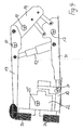
- longwall equipment comprises first a shield support frame 10 with a bottom skid 11 on which two punches 12 are attached in a parallel arrangement, of which in FIG. 1 only one stamp is recognizable and carry a hanging end cap 13 at its upper end. While the Hangendkappe 13 protrudes at its front (left) end in the direction of the still to be described extraction machine, at the rear (right) end of the Hangendkappe 13 a crash plate 14 is articulated by means of a hinge 15, wherein the broken shield of the two in the side view on the Bodenkufe 11 resting support arms 16 is supported.
- three inclination sensors 17 are mounted in the illustrated embodiment, namely a tilt sensor 17 on the Bodenkufe 11, a tilt sensor 17 in the rear of the hanging wall 13 in the vicinity of the hinge 15 and a tilt sensor 17 on the fracture shield 14.
- the support arms 16, also a tilt sensor, of the four possible tilt sensors 17 three inclination sensors must be installed in order to determine the position of the shield support frame in a working space with the determined inclination values
- the in FIG. 1 tilt sensor 17 shown in the rear of the hanging wall 13 are displaced in the front cap area, if in the cap profile for this purpose a protected space is available.
- the invention is not limited to the concrete in FIG. 1 illustrated arrangement of the inclination sensors limited, but includes all possible combinations of three inclination sensors to the four moving parts of the shield support frame.
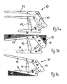
- FIGS. 8a to 8c This can be done in FIGS. 1 or 2 shown in a side view shield support frame 10 while basically have three types with respect to its Bodenkufe.
- the Bodenkufe 11 consists of two partial skids, which are, however, firmly connected to each other via a solid steel structure 28, so that there is a so-called “tunnel skid".
- this tunnel skid has a better height mobility, but it comes to higher surface pressures and thus to a higher tendency to sink the two skids in the lying.
- the Bodenkufe be formed with two partial runners, which are connected to each other via a bottom plate 29, so that there is a larger bearing surface for the Bodenkufe.
- the surface pressure and thus the tendency is reduced that the Schildausbaugestelle in particular in the area of the tip tip in the Push in lying down.
- this design limits the mobility for rapid changes in the height of the sign, because in particular at a rapid increase in the height of the sign, the stepping 37 can not follow a fast emerging longwall conveyor, because the walker then abuts the closed floor panel 29, which limits the possibility of height adjustment.
- FIG. 8c an embodiment is shown, which is preferably used in planing operations at a low seam thickness, such as below 1.5m.
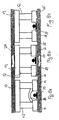
- separate individual runners 35 and 36 are provided, between which the walking mechanism 37 is arranged such that the right-hand runner 35 in the direction of travel can be lifted independently of the left-hand runner 36 in the walking direction.
- This separation of the individual runners 35 and 36 allows the steps of the shield support frame 10 in the so-called Elephant-Step, by means of which a sinking of the two single skids 35 and 36 in the horizontal 23 and accumulation and postponement of debris in front of the individual runners 35, 36 can be counteracted.
- FIG. 1 illustrated shield support frame 10 is struck on a longwall conveyor 20, which also has a tilt sensor 21, so that in terms of the control of the longwall equipment in general also here data regarding the conveyor position can be obtained.
- a recovery machine in the form of a Walzenschrämladers 22 is guided with an upper roller 23 and a lower roller 24, wherein a tilt sensor 25 is disposed in the region of the Walzenschrämladers 22, further, a sensor 26 for detecting the respective location of the Walzenschrämladers 22 in Strut and reed rods 27 for measuring the cutting height of the Walzenschrämladers 22.
- the metrological equipment of the longwall equipment is complemented by the arrangement of sensors 18 on the punches 12, by means of which the change in the altitude of the hanging wall 13 by determining the dropout height of the punch 12 is possible. Furthermore, a Wegmesssystem 19 is integrated in the Bodenkufe 11, by means of which the respective Schreithub the shield support frame 10 in relation to the longwall conveyor 20 can be determined.
- the arrangement of the inclination sensor 21 on the longwall conveyor 20 is not absolutely necessary as long as the inclination sensor 25 is set up on the drum skid loader 22. In such a case, however, the inclination sensor 21 may be additionally provided to improve the measurement accuracy.
- the shield support frame 10 can be due to the known kinematics of the shield support frame 10 depending on the position of Bodenkufe 11, 14 Bruchschild and Hangendkappe 13 to each other determine the heights h 1 , h 2 and h 3 , wherein the height h 1 for determining the bank level height of the longwall 30, while the height h 2 is a measure of a possible overhang in a fully extended shield frame stand or for annensetzergefahr, while the height h 3 can be used to consider the convergence.
- the determination of the heights h 1 , h 2 and h 3 can The values measured by these sensors 17 are compared in a computing unit (not shown) with the basic data stored therein for the geometric alignment of the components and their movement behavior relative to one another.
- a computing unit not shown
- the individual shield expansion point 10 are calibrated after their installation in the longwall equipment by measuring the hang-end cap 13, the fracture shield 14 and the bottom skid 11 by means of a hand-held inclinometer in the installed state and the measured values are entered into the corresponding control of the shield construction frame 10. If the altitude values h 1 , h 2 and h 3 are then displayed in the blade control, these height values can be measured with tape measures and then the inclination sensors can be calibrated accordingly.
- the conveyor 20 to which the respective individual shield removal point 10 of the longwall equipment are struck, as well as guided on the conveyor 20 extraction machine 22 in the form of a Walzenschrämladers 19 with an upper roller 23 and a lower roller 24th be equipped with appropriate inclination sensors, so that the inclusion of these inclination values, the total determined roller cutting height of the Walzenschrämladers 22 can be set in relation to the provided by the Schildausbaugestellen 10 Strebö réelle 30.
- a risk of collision in the region of the front edge of the Hangendkappe 13 sets.
- the height values h 1 , h 2 and h 3 can also give information about the inevitable in underground operation by loading the hanging wall 31 on the hangover cap 13 of standing on the floor 32 Shield frame 10 resulting convergence, as indicated by the loading arrows 34 , Between the hanging wall 31 and the lying 32 is in FIG. 5 schematically the coal burst 33 shown.
- shielding expansion frame 10 In the position determined by the values of the tilt sensors 17 in FIG. 6 illustrated shielding expansion frame 10 is the breaking edge 35 in the rear region of the hanging wall 13, which means that the load capacity of the shielding rack is optimally utilized, because the introduction of the expansion forces in the area of the shielding rack takes place, in which the best possible effect can be achieved with respect to the hillside control. Eventual, on the surface of the Hangendkappe 13 forming mountain upholstery can be stripped when walking the shield support frame 10. The Bodenkufe stands slightly rising and can thus slide well on possibly on itself on the footwall 32 forming heap. The result of such a position of the shield support frame 10 is that hardly any debris is to be expected when advancing the expansion, so that optionally also an automatic and trouble-free operation of the longwall equipment is possible.
- the inclination measurement data obtained at individual shielding outstations 10 as well as at conveyors 20 and mining machine 22 it is also possible with the inclination measurement data obtained at individual shielding outstations 10 as well as at conveyors 20 and mining machine 22 to record the behavior of the longwall equipment overall over the entire length of the strut. For example, deviations occur in individual areas of the strut due to geological anomalies such as saddle or trough areas As the extraction and expansion work to other areas of the strut, the corresponding problem areas in the monitoring are immediately visible, so that in these areas, the extraction and expansion work can be adjusted in a targeted manner accordingly.
Landscapes
- Engineering & Computer Science (AREA)
- Mining & Mineral Resources (AREA)
- Life Sciences & Earth Sciences (AREA)
- General Life Sciences & Earth Sciences (AREA)
- Geochemistry & Mineralogy (AREA)
- Geology (AREA)
- Mechanical Engineering (AREA)
- Excavating Of Shafts Or Tunnels (AREA)
- Piles And Underground Anchors (AREA)
- Lining And Supports For Tunnels (AREA)
Claims (20)
- Procédé servant à commander des exploitations de taille dans le domaine de l'exploitation de mines de charbon souterraines, présentant un convoyeur de taille (20), au moins une machine d'abattage (22) ainsi qu'un soutènement à bouclier hydraulique, dans le cadre duquel on détermine, au moyen de capteurs d'inclinaison (17) mis en place au niveau d'au moins trois des quatre composants principaux de chaque châssis de soutènement à bouclier (10), tels que la semelle (11), le bouclier de rupture (14), les bras porteurs (16), et au niveau de la zone côté rupture du chapeau de toit (13), l'inclinaison des composants de bouclier par rapport à l'horizontale dans le sens de progression et où on calcule, à partir des données mesurées dans une unité de calcul, par la comparaison avec les données de base mémorisées dans l'unité de calcul, définissant l'orientation géométrique des composants et leur déplacement au cours de la progression, la hauteur (h1) du châssis de soutènement à bouclier (10) respectivement perpendiculaire à la stratification, comme mesure pour l'ouverture de taille (30) au niveau de l'extrémité avant du chapeau de toit (13).
- Procédé selon la revendication 1, dans le cadre duquel un châssis de soutènement à bouclier (10) comprenant une semelle partagée est utilisé, sachant que le patin (37) du châssis de soutènement à bouclier est disposé entre les deux semelles individuelles (35, 36) du châssis de soutènement à bouclier (10) et que respectivement un capteur d'inclinaison (17) est disposé au niveau des deux semelles individuelles (35, 36).
- Procédé selon la revendication 2, dans le cadre duquel on calcule, pour chacune des deux semelles individuelles (35, 36), la hauteur de bouclier respective à partir des angles d'inclinaison mesurés pour le chapeau de toit (13), le bouclier de rupture (14) et pour la semelle individuelle droite (35) et la semelle individuelle gauche (36) du châssis de soutènement à bouclier (10).
- Procédé selon la revendication 3, dans le cadre duquel on calcule, à partir de la valeur moyenne des valeurs de hauteurs de bouclier calculées pour les deux semelles individuelles (35, 36), la hauteur de bouclier déterminée pour le châssis de soutènement à bouclier (10).
- Procédé selon l'une quelconque des revendications 1 à 4, dans le cadre duquel on calcule, dans l'unité de calcul, en complément les hauteurs (h2, h3) perpendiculaires à la stratification à l'intérieur du châssis de soutènement à bouclier (10), dans la zone du point de départ des étançons (12) au niveau du chapeau de toit (13) et dans la zone de l'articulation (15) entre le chapeau de toit (13) et le chapeau de bouclier (14).
- Procédé selon l'une quelconque des revendications 1 à 4, dans le cadre duquel les capteurs d'inclinaison (17) mis en place au niveau des composants de bouclier (11, 13, 14) sont placés en des emplacements présentant un angle d'inflexion minimal des composants.
- Procédé selon l'une quelconque des revendications 1 à 6, caractérisé en ce qu'on détermine, au moyen de capteurs de pression, la pression interne d'étançon des étançons (12) du châssis de soutènement à bouclier (10).
- Procédé selon l'une quelconque des revendications 1 à 7, dans le cadre duquel une flexion, correspondant à la charge déterminée des composants de bouclier (11, 13, 14), est intégrée sous la forme d'une compensation d'erreur dépendant de la charge, dans le calcul des dimensions relatives aux hauteurs (h1, h2, h3) en fonction de l'absorption de charge, représentée par la pression interne d'étançon, du châssis de soutènement à bouclier (10).
- Procédé selon l'une quelconque des revendications 1 à 8, dans le cadre duquel, on détermine, par l'intermédiaire du capteur d'inclinaison (17) mis en place au niveau du chapeau de toit (13) du châssis de soutènement à bouclier (10), l'inclinaison du chapeau de toit (13) par rapport à l'horizontale, de manière transversale par rapport au sens de progression.
- Procédé selon l'une quelconque des revendications 1 à 9, dans le cadre duquel on détermine, pour une machine d'abattage réalisée sous la forme d'une haveuse-chargeuse à tambour (22), les hauteurs de coupe du tambour (23) en avant réalisant la coupe partielle supérieure et du tambour (24) réalisant la coupe partielle inférieure, sur la base de capteurs détectant l'emplacement des bras de support des tambours et où, lorsque la machine d'abattage (22) passe le long de chaque châssis de soutènement à bouclier (10), la hauteur totale de coupe des tambours est exprimée sous la forme d'un rapport par rapport à l'ouverture de taille (30) déterminée par calcul au niveau du châssis de soutènement à bouclier (10) concerné.
- Procédé selon l'une quelconque des revendications 1 à 10, dans le cadre duquel la hauteur de coupe des tambours déterminée pour un emplacement, associé à un châssis de soutènement à bouclier (10), de la machine d'abattage (22) est associée, lors d'une analyse synchrone d'un point de vue spatial, à l'ouverture de taille (30) constatée consécutivement pour cette position avec un report du montage du chapeau de toit (13) du châssis de soutènement à bouclier (10) associé.
- Procédé selon l'une quelconque des revendications 1 à 11, dans le cadre duquel on détermine l'inclinaison du convoyeur (20) et/ou de la machine d'abattage (22) par rapport à l'horizontale dans le sens de progression des châssis de soutènement à bouclier (10), au moyen de capteurs d'inclinaison (21, 25) mis en place au niveau du convoyeur (20) et/ou de la machine d'abattage (22).
- Procédé selon la revendication 12, dans le cadre duquel l'angle d'inclinaison du convoyeur (20) et/ou de la machine d'abattage (22) est exprimé sous la forme d'un rapport par rapport à l'angle d'inclinaison déterminé au niveau de la semelle (11) du châssis de soutènement à bouclier (10) et/ou au niveau du chapeau de toit (13), et en ce que l'angle de différence en résultant est intégré dans le calcul de l'ouverture de taille (30) s'ajustant dans le cas de plusieurs cycles de progression de suivant les uns les autres du châssis de soutènement à bouclier (10).
- Procédé selon l'une quelconque des revendications 1 à 13, dans le cadre duquel on détecte les valeurs relatives aux hauteurs (h1, h2, h3) décrivant la géométrie du châssis de soutènement à bouclier (10) au niveau de l'extrémité avant du chapeau de toit (13), dans la zone du point de départ des étançons (12) au niveau du chapeau de toit (13) et dans la zone de l'articulation (15) entre le chapeau de toit (13) et le chapeau de bouclier (14) sur l'axe du temps, et où on détermine, à partir des variations des valeurs de mesure sur l'axe de temps, la convergence provoquée par la charge exercée par la roche.
- Procédé selon la revendication 14, dans le cadre duquel la convergence est représentée sous la forme de paramètres de convergence par rapport à l'ouverture de taille (30), au niveau de l'extrémité avant du chapeau de toit (13), à l'inclinaison du chapeau de toit (13) par rapport à l'horizontale dans le sens de progression, à l'abaissement des étançons (12) supportant le chapeau de toit (13) et à l'extrémité côté rupture du chapeau de toit (13).
- Procédé selon la revendication 14 ou 15, dans le cadre duquel on détermine, à partir des paramètres de convergence et/ou de l'inclinaison du chapeau de toit (13), dans le sens de progression, la position du châssis de soutènement à bouclier (10) eu égard à l'introduction de force de support.
- Procédé selon l'une quelconque des revendications 1 à 6, dans le cadre duquel on utilise en tant que capteurs d'inclinaison (17) des capteurs d'accélération, qui détectent dans l'espace, par l'intermédiaire de l'écart par rapport à l'accélération de la force gravitationnelle, la position angulaire du capteur d'accélération.
- Procédé selon la revendication 17, dans le cadre duquel on vérifie et on corrige les valeurs de mesure déterminées par les capteurs d'accélération, au moyen d'un procédé d'affaiblissement approprié, afin de supprimer des erreurs provoquées par les oscillations des composants utilisés.
- Procédé selon l'une quelconque des revendications 1 à 18, dans le cadre duquel la position des divers châssis de soutènement à bouclier (10) est rendue visible d'un point de vue optique dans une unité d'affichage.
- Procédé selon la revendication 19, dans le cadre duquel on représente des écarts connus, réputés pour former un risque, de valeurs théoriques prédéfinies dans l'unité d'affichage dans une couleur voyante.
Priority Applications (1)
| Application Number | Priority Date | Filing Date | Title |
|---|---|---|---|
| PL08715851T PL2247823T3 (pl) | 2008-02-19 | 2008-02-19 | Sposób sterowania wybieraniem ścianowym |
Applications Claiming Priority (1)
| Application Number | Priority Date | Filing Date | Title |
|---|---|---|---|
| PCT/EP2008/001262 WO2009103303A1 (fr) | 2008-02-19 | 2008-02-19 | Procédé pour assurer la commande d'installations d'exploitation par taille |
Publications (2)
| Publication Number | Publication Date |
|---|---|
| EP2247823A1 EP2247823A1 (fr) | 2010-11-10 |
| EP2247823B1 true EP2247823B1 (fr) | 2014-06-25 |
Family
ID=40039720
Family Applications (1)
| Application Number | Title | Priority Date | Filing Date |
|---|---|---|---|
| EP08715851.5A Not-in-force EP2247823B1 (fr) | 2008-02-19 | 2008-02-19 | Procédé pour assurer la commande d'installations d'exploitation par taille |
Country Status (7)
| Country | Link |
|---|---|
| US (1) | US8672414B2 (fr) |
| EP (1) | EP2247823B1 (fr) |
| CN (1) | CN101970795B (fr) |
| AU (1) | AU2008351272B2 (fr) |
| EA (1) | EA016460B1 (fr) |
| PL (1) | PL2247823T3 (fr) |
| WO (1) | WO2009103303A1 (fr) |
Families Citing this family (21)
| Publication number | Priority date | Publication date | Assignee | Title |
|---|---|---|---|---|
| EP2247825B1 (fr) * | 2008-02-19 | 2014-11-19 | Rag Aktiengesellschaft | Procede pour pratiquer de maniere automatique une ouverture definie de taille dans des systemes de veines de mines de houille |
| WO2012031610A1 (fr) | 2010-09-07 | 2012-03-15 | Rag Aktiengesellschaft | Commande du travail d'abattage dans l'exploitation de mines de charbon souterraines, réalisée au moyen d'un appareil de mesure à laser |
| CN102022131A (zh) * | 2010-09-29 | 2011-04-20 | 北京诚田恒业煤矿设备有限公司 | 一种滑柱式自移液压支架 |
| WO2012089230A1 (fr) | 2010-12-30 | 2012-07-05 | Rag Aktiengesellschaft | Équipement de taille comprenant un niveau à eau posé dessus pour déterminer la position en hauteur d'éléments individuels de l'équipement de taille |
| CN102392664B (zh) * | 2011-07-26 | 2014-04-16 | 北京天地玛珂电液控制系统有限公司 | 一种带倾角传感器的液压支架及其高度测量方法 |
| CN102353962B (zh) * | 2011-08-25 | 2013-05-01 | 北京天地玛珂电液控制系统有限公司 | 一种液压支架的无线测距装置和测距方法以及使用该装置和方法的液压支架 |
| CN102418525B (zh) * | 2011-10-28 | 2014-07-09 | 山西晋城无烟煤矿业集团有限责任公司 | 软煤层长壁大采高综合机械化采煤末采方法 |
| CN102536239B (zh) * | 2012-01-06 | 2014-03-26 | 何满潮 | 一种长壁工作面无煤柱开采方法 |
| UA109514C2 (uk) * | 2012-04-02 | 2015-08-25 | Забійне обладнання з покладеними між забійним конвеєром і каркасами щитового кріплення шланговими нівелірами | |
| UA109515C2 (uk) * | 2012-04-02 | 2015-08-25 | Забійне обладнання з покладеними на його каркасах щитового кріплення шланговими нівелірами | |
| PL2803818T3 (pl) * | 2013-05-13 | 2019-07-31 | Caterpillar Global Mining Europe Gmbh | Sposób sterowania wrębiarką |
| DE102016002275A1 (de) * | 2015-02-28 | 2016-09-01 | Tiefenbach Control Systems Gmbh | Verfahren zum Betrieb der Abbaumaschine zum Kohleabbau im untertätigen Streb eines Steinkohlebergwerkes |
| CN105041359A (zh) * | 2015-05-29 | 2015-11-11 | 苏州贝多环保技术有限公司 | 一种综采工作面液压支架的安装方法 |
| US10208592B2 (en) * | 2015-12-02 | 2019-02-19 | Joy Global Underground Mining Llc | Longwall optimization control |
| CN106948850B (zh) * | 2017-04-28 | 2018-10-09 | 重庆工程职业技术学院 | 液压支架近似直线轨迹四杆机构 |
| GB2576171A (en) * | 2018-08-07 | 2020-02-12 | Caterpillar Global Mining Gmbh | Self-advancing roof support for a longwall mining system |
| GB2576172A (en) | 2018-08-07 | 2020-02-12 | Caterpillar Global Mining Gmbh | Shearing system for longwall mining |
| CN110906903A (zh) * | 2019-12-13 | 2020-03-24 | 山东科技大学 | 一种快速获得综采工作面顶板下沉量的方法 |
| CN115013023B (zh) * | 2022-07-20 | 2025-05-13 | 山东科技大学 | 一种具有煤壁片帮快速响应功能的液压支架 |
| CN115597537B (zh) * | 2022-09-29 | 2025-08-12 | 西安煤矿机械有限公司 | 一种采煤机采高监测方法 |
| CN119145895B (zh) * | 2024-11-11 | 2025-03-04 | 浙江中煤液压机械有限公司 | 一种基于可视化和自适应技术的支架移架方法 |
Family Cites Families (15)
| Publication number | Priority date | Publication date | Assignee | Title |
|---|---|---|---|---|
| DE2714506C2 (de) * | 1977-04-01 | 1982-06-16 | Bergwerksverband Gmbh, 4300 Essen | Verfahren und Einrichtung zur Überwachung und Steuerung von Strebausrüstungen |
| DE3100093A1 (de) | 1981-01-03 | 1982-08-05 | Gewerkschaft Eisenhütte Westfalia, 4670 Lünen | Vorrichtung zur begrenzung des ausbauwiderstandes eines hydraulischen ausbauschildes |
| DE2917609C2 (de) * | 1979-05-02 | 1985-12-19 | Gewerkschaft Eisenhütte Westfalia, 4670 Lünen | Einrichtung zur Steuerung der Vorpfändkappen eines Schreitausbaus in Abhängigkeit vom Abbaufortschritt |
| DE3605236A1 (de) * | 1986-02-19 | 1987-08-20 | Gewerk Eisenhuette Westfalia | Steuereinrichtung fuer untertaegige ausbaueinheiten |
| PL149218B1 (en) * | 1986-04-03 | 1990-01-31 | Method of filling mined-out longwall workings and filling stopping therefor | |
| DE3620880C1 (en) | 1986-06-21 | 1987-06-04 | Hemscheidt Maschf Hermann | Hydraulic self-advancing support frame |
| DE3743758A1 (de) * | 1987-12-23 | 1989-07-13 | Bochumer Eisen Heintzmann | Verfahren zur lenkung der abbaufront |
| GB9122146D0 (en) * | 1991-10-18 | 1991-11-27 | Gullick Dobson Ltd | Mine roof supports |
| DE19528378C1 (de) * | 1995-08-02 | 1996-11-28 | Dbt Gmbh | Hydraulisches Schildausbaugestell |
| DE19636389B4 (de) * | 1996-09-07 | 2004-03-11 | Dbt Automation Gmbh | Verfahren und Einrichtung zur Lastüberwachung von hydraulischen Schildausbaugestellen für den Untertagebergbau |
| WO2001081726A1 (fr) * | 2000-04-26 | 2001-11-01 | Commonwealth Scientific And Industrial Research Organisation | Machine et procede d'extraction miniere |
| CN1354318A (zh) * | 2000-11-17 | 2002-06-19 | 连云港市白集煤矿 | 急倾斜松软厚煤层走向长壁倾斜分层采煤技术 |
| CN100567703C (zh) * | 2005-05-19 | 2009-12-09 | 兖矿集团有限公司 | 长壁采煤法综采工艺 |
| DE102007035848C5 (de) * | 2007-07-31 | 2018-11-15 | Marco Systemanalyse Und Entwicklung Gmbh | Ausbauschild und Verfahren zur Steuerung oder Positionsbestimmung eines Ausbauschildes |
| US8244509B2 (en) * | 2007-08-01 | 2012-08-14 | Schlumberger Technology Corporation | Method for managing production from a hydrocarbon producing reservoir in real-time |
-
2008
- 2008-02-19 PL PL08715851T patent/PL2247823T3/pl unknown
- 2008-02-19 WO PCT/EP2008/001262 patent/WO2009103303A1/fr not_active Ceased
- 2008-02-19 EA EA201001132A patent/EA016460B1/ru not_active IP Right Cessation
- 2008-02-19 AU AU2008351272A patent/AU2008351272B2/en active Active
- 2008-02-19 EP EP08715851.5A patent/EP2247823B1/fr not_active Not-in-force
- 2008-02-19 CN CN2008801271319A patent/CN101970795B/zh active Active
- 2008-02-19 US US12/918,473 patent/US8672414B2/en not_active Expired - Fee Related
Also Published As
| Publication number | Publication date |
|---|---|
| EA016460B1 (ru) | 2012-05-30 |
| PL2247823T3 (pl) | 2015-01-30 |
| EA201001132A1 (ru) | 2011-02-28 |
| EP2247823A1 (fr) | 2010-11-10 |
| AU2008351272A1 (en) | 2009-08-27 |
| WO2009103303A1 (fr) | 2009-08-27 |
| AU2008351272B2 (en) | 2013-01-10 |
| CN101970795B (zh) | 2013-06-12 |
| US20110049964A1 (en) | 2011-03-03 |
| CN101970795A (zh) | 2011-02-09 |
| US8672414B2 (en) | 2014-03-18 |
Similar Documents
| Publication | Publication Date | Title |
|---|---|---|
| EP2247823B1 (fr) | Procédé pour assurer la commande d'installations d'exploitation par taille | |
| EP2247825B1 (fr) | Procede pour pratiquer de maniere automatique une ouverture definie de taille dans des systemes de veines de mines de houille | |
| DE102009030130B9 (de) | Verfahren zur automatisierten Herstellung einer definierten Streböffnung durch neigungsgestützte Radarnavigation der Walze bei einem Walzenschrämlader und eine Vorrichtung hierfür | |
| EP2247824B1 (fr) | Procédé pour pratiquer de manière automatique une ouverture définie de taille dans des systèmes de veines de mines de houille souterraines | |
| EP2467577B1 (fr) | Procédé pour pratiquer une ouverture de taille en utilisant des systèmes d'automatisation | |
| EP2247826B1 (fr) | Procede de maintien regule d'un ecart chapeau-grisou dans des installations d'exploitation par taille | |
| WO2009103306A1 (fr) | Procede pour stabiliser la colonne de soutenement a bouclier dans une installation d'exploitation par taille guidee dans l'inclinaison de filons | |
| DE2714506C2 (de) | Verfahren und Einrichtung zur Überwachung und Steuerung von Strebausrüstungen | |
| DE19636389B4 (de) | Verfahren und Einrichtung zur Lastüberwachung von hydraulischen Schildausbaugestellen für den Untertagebergbau | |
| EP2366059B1 (de) | Verfahren zur einstellung einer automatischen niveausteuerung des hobels in hobelbetrieben des steinkohlenbergbaus | |
| EP2659092B1 (fr) | Equipement de transporteur en taille muni d'un dispositif de mesure de nivellement utilisant un tuyau afin de déterminer la hauteur d'éléments individuels du transporteur de taille | |
| DE102007035848C5 (de) | Ausbauschild und Verfahren zur Steuerung oder Positionsbestimmung eines Ausbauschildes | |
| DE102008047582B3 (de) | Strebausrüstung mit einem höhenverstellbar auf dem Strebförderer geführten Walzenschrämlader | |
| EP2242900A1 (fr) | Procédé pour assurer la commande d'installations d'exploitation par taille, par identification de couches limites | |
| DE4328863C2 (de) | Abbaueinrichtung für den Untertagebergbau | |
| WO2012031610A1 (fr) | Commande du travail d'abattage dans l'exploitation de mines de charbon souterraines, réalisée au moyen d'un appareil de mesure à laser | |
| WO2008011647A1 (fr) | Dispositif d'appui pour une abatteuse-chargeuse | |
| EP2834464B1 (fr) | Équipement de taille muni de niveaux à eau posés sur ses éléments de soutènement bouclier | |
| DE102008053133A1 (de) | Verfahren zur automatischen Herstellung einer definierten Streböffnung in Hobelbetrieben des Steinkohlenbergbaus | |
| DE102007012678B3 (de) | Verfahren zum Steuern von Strebbetrieben im untertägigen Steinkohlenbergbau | |
| DE2413247A1 (de) | Schildausbaugestell | |
| DE3339611C1 (de) | Ausbauanordnung zum stoßartigen Gewinnen mit einer Kurzfrontmaschine im Streb | |
| DE10106753A1 (de) | Steuerung des Vorschubs und des Schneidwalzenhöhenniveaus eines Walzenschrämladers in Abhängigkeit von der Belastung des Walzentragarmes | |
| DE2701641B2 (de) | Hilfsausbau für den Übergang Streb-Strecke | |
| DE1947376B (de) | Wandernder Strebausbau für untertägige Grubenbetriebe |
Legal Events
| Date | Code | Title | Description |
|---|---|---|---|
| PUAI | Public reference made under article 153(3) epc to a published international application that has entered the european phase |
Free format text: ORIGINAL CODE: 0009012 |
|
| 17P | Request for examination filed |
Effective date: 20100722 |
|
| AK | Designated contracting states |
Kind code of ref document: A1 Designated state(s): AT BE BG CH CY CZ DE DK EE ES FI FR GB GR HR HU IE IS IT LI LT LU LV MC MT NL NO PL PT RO SE SI SK TR |
|
| AX | Request for extension of the european patent |
Extension state: AL BA MK RS |
|
| RIN1 | Information on inventor provided before grant (corrected) |
Inventor name: JUNKER, MARTIN Inventor name: MOZAR, ARMIN |
|
| DAX | Request for extension of the european patent (deleted) | ||
| GRAP | Despatch of communication of intention to grant a patent |
Free format text: ORIGINAL CODE: EPIDOSNIGR1 |
|
| INTG | Intention to grant announced |
Effective date: 20140122 |
|
| GRAS | Grant fee paid |
Free format text: ORIGINAL CODE: EPIDOSNIGR3 |
|
| GRAA | (expected) grant |
Free format text: ORIGINAL CODE: 0009210 |
|
| AK | Designated contracting states |
Kind code of ref document: B1 Designated state(s): AT BE BG CH CY CZ DE DK EE ES FI FR GB GR HR HU IE IS IT LI LT LU LV MC MT NL NO PL PT RO SE SI SK TR |
|
| REG | Reference to a national code |
Ref country code: GB Ref legal event code: FG4D Free format text: NOT ENGLISH |
|
| REG | Reference to a national code |
Ref country code: CH Ref legal event code: EP |
|
| REG | Reference to a national code |
Ref country code: AT Ref legal event code: REF Ref document number: 674846 Country of ref document: AT Kind code of ref document: T Effective date: 20140715 |
|
| REG | Reference to a national code |
Ref country code: IE Ref legal event code: FG4D Free format text: LANGUAGE OF EP DOCUMENT: GERMAN |
|
| REG | Reference to a national code |
Ref country code: DE Ref legal event code: R096 Ref document number: 502008011931 Country of ref document: DE Effective date: 20140814 |
|
| PG25 | Lapsed in a contracting state [announced via postgrant information from national office to epo] |
Ref country code: NO Free format text: LAPSE BECAUSE OF FAILURE TO SUBMIT A TRANSLATION OF THE DESCRIPTION OR TO PAY THE FEE WITHIN THE PRESCRIBED TIME-LIMIT Effective date: 20140925 Ref country code: FI Free format text: LAPSE BECAUSE OF FAILURE TO SUBMIT A TRANSLATION OF THE DESCRIPTION OR TO PAY THE FEE WITHIN THE PRESCRIBED TIME-LIMIT Effective date: 20140625 Ref country code: CY Free format text: LAPSE BECAUSE OF FAILURE TO SUBMIT A TRANSLATION OF THE DESCRIPTION OR TO PAY THE FEE WITHIN THE PRESCRIBED TIME-LIMIT Effective date: 20140625 Ref country code: GR Free format text: LAPSE BECAUSE OF FAILURE TO SUBMIT A TRANSLATION OF THE DESCRIPTION OR TO PAY THE FEE WITHIN THE PRESCRIBED TIME-LIMIT Effective date: 20140926 Ref country code: LT Free format text: LAPSE BECAUSE OF FAILURE TO SUBMIT A TRANSLATION OF THE DESCRIPTION OR TO PAY THE FEE WITHIN THE PRESCRIBED TIME-LIMIT Effective date: 20140625 |
|
| REG | Reference to a national code |
Ref country code: NL Ref legal event code: VDEP Effective date: 20140625 |
|
| REG | Reference to a national code |
Ref country code: LT Ref legal event code: MG4D |
|
| PG25 | Lapsed in a contracting state [announced via postgrant information from national office to epo] |
Ref country code: LV Free format text: LAPSE BECAUSE OF FAILURE TO SUBMIT A TRANSLATION OF THE DESCRIPTION OR TO PAY THE FEE WITHIN THE PRESCRIBED TIME-LIMIT Effective date: 20140625 Ref country code: HR Free format text: LAPSE BECAUSE OF FAILURE TO SUBMIT A TRANSLATION OF THE DESCRIPTION OR TO PAY THE FEE WITHIN THE PRESCRIBED TIME-LIMIT Effective date: 20140625 Ref country code: SE Free format text: LAPSE BECAUSE OF FAILURE TO SUBMIT A TRANSLATION OF THE DESCRIPTION OR TO PAY THE FEE WITHIN THE PRESCRIBED TIME-LIMIT Effective date: 20140625 |
|
| PG25 | Lapsed in a contracting state [announced via postgrant information from national office to epo] |
Ref country code: RO Free format text: LAPSE BECAUSE OF FAILURE TO SUBMIT A TRANSLATION OF THE DESCRIPTION OR TO PAY THE FEE WITHIN THE PRESCRIBED TIME-LIMIT Effective date: 20140625 Ref country code: PT Free format text: LAPSE BECAUSE OF FAILURE TO SUBMIT A TRANSLATION OF THE DESCRIPTION OR TO PAY THE FEE WITHIN THE PRESCRIBED TIME-LIMIT Effective date: 20141027 Ref country code: SK Free format text: LAPSE BECAUSE OF FAILURE TO SUBMIT A TRANSLATION OF THE DESCRIPTION OR TO PAY THE FEE WITHIN THE PRESCRIBED TIME-LIMIT Effective date: 20140625 Ref country code: ES Free format text: LAPSE BECAUSE OF FAILURE TO SUBMIT A TRANSLATION OF THE DESCRIPTION OR TO PAY THE FEE WITHIN THE PRESCRIBED TIME-LIMIT Effective date: 20140625 Ref country code: EE Free format text: LAPSE BECAUSE OF FAILURE TO SUBMIT A TRANSLATION OF THE DESCRIPTION OR TO PAY THE FEE WITHIN THE PRESCRIBED TIME-LIMIT Effective date: 20140625 |
|
| REG | Reference to a national code |
Ref country code: PL Ref legal event code: T3 |
|
| PG25 | Lapsed in a contracting state [announced via postgrant information from national office to epo] |
Ref country code: NL Free format text: LAPSE BECAUSE OF FAILURE TO SUBMIT A TRANSLATION OF THE DESCRIPTION OR TO PAY THE FEE WITHIN THE PRESCRIBED TIME-LIMIT Effective date: 20140625 Ref country code: IS Free format text: LAPSE BECAUSE OF FAILURE TO SUBMIT A TRANSLATION OF THE DESCRIPTION OR TO PAY THE FEE WITHIN THE PRESCRIBED TIME-LIMIT Effective date: 20141025 |
|
| REG | Reference to a national code |
Ref country code: DE Ref legal event code: R097 Ref document number: 502008011931 Country of ref document: DE |
|
| PG25 | Lapsed in a contracting state [announced via postgrant information from national office to epo] |
Ref country code: IT Free format text: LAPSE BECAUSE OF FAILURE TO SUBMIT A TRANSLATION OF THE DESCRIPTION OR TO PAY THE FEE WITHIN THE PRESCRIBED TIME-LIMIT Effective date: 20140625 Ref country code: DK Free format text: LAPSE BECAUSE OF FAILURE TO SUBMIT A TRANSLATION OF THE DESCRIPTION OR TO PAY THE FEE WITHIN THE PRESCRIBED TIME-LIMIT Effective date: 20140625 |
|
| PLBE | No opposition filed within time limit |
Free format text: ORIGINAL CODE: 0009261 |
|
| STAA | Information on the status of an ep patent application or granted ep patent |
Free format text: STATUS: NO OPPOSITION FILED WITHIN TIME LIMIT |
|
| REG | Reference to a national code |
Ref country code: DE Ref document number: 502008011931 Country of ref document: DE Representative=s name: MANITZ FINSTERWALD PATENTANWAELTE PARTMBB, DE Ref legal event code: R082 |
|
| 26N | No opposition filed |
Effective date: 20150326 |
|
| PG25 | Lapsed in a contracting state [announced via postgrant information from national office to epo] |
Ref country code: BE Free format text: LAPSE BECAUSE OF NON-PAYMENT OF DUE FEES Effective date: 20150228 |
|
| PG25 | Lapsed in a contracting state [announced via postgrant information from national office to epo] |
Ref country code: LU Free format text: LAPSE BECAUSE OF FAILURE TO SUBMIT A TRANSLATION OF THE DESCRIPTION OR TO PAY THE FEE WITHIN THE PRESCRIBED TIME-LIMIT Effective date: 20150219 |
|
| REG | Reference to a national code |
Ref country code: CH Ref legal event code: PL |
|
| GBPC | Gb: european patent ceased through non-payment of renewal fee |
Effective date: 20150219 |
|
| PG25 | Lapsed in a contracting state [announced via postgrant information from national office to epo] |
Ref country code: CH Free format text: LAPSE BECAUSE OF NON-PAYMENT OF DUE FEES Effective date: 20150228 Ref country code: LI Free format text: LAPSE BECAUSE OF NON-PAYMENT OF DUE FEES Effective date: 20150228 Ref country code: MC Free format text: LAPSE BECAUSE OF FAILURE TO SUBMIT A TRANSLATION OF THE DESCRIPTION OR TO PAY THE FEE WITHIN THE PRESCRIBED TIME-LIMIT Effective date: 20140625 |
|
| REG | Reference to a national code |
Ref country code: IE Ref legal event code: MM4A |
|
| REG | Reference to a national code |
Ref country code: FR Ref legal event code: ST Effective date: 20151030 |
|
| PG25 | Lapsed in a contracting state [announced via postgrant information from national office to epo] |
Ref country code: SI Free format text: LAPSE BECAUSE OF FAILURE TO SUBMIT A TRANSLATION OF THE DESCRIPTION OR TO PAY THE FEE WITHIN THE PRESCRIBED TIME-LIMIT Effective date: 20140625 |
|
| PG25 | Lapsed in a contracting state [announced via postgrant information from national office to epo] |
Ref country code: GB Free format text: LAPSE BECAUSE OF NON-PAYMENT OF DUE FEES Effective date: 20150219 Ref country code: IE Free format text: LAPSE BECAUSE OF NON-PAYMENT OF DUE FEES Effective date: 20150219 |
|
| PG25 | Lapsed in a contracting state [announced via postgrant information from national office to epo] |
Ref country code: FR Free format text: LAPSE BECAUSE OF NON-PAYMENT OF DUE FEES Effective date: 20150302 |
|
| REG | Reference to a national code |
Ref country code: AT Ref legal event code: MM01 Ref document number: 674846 Country of ref document: AT Kind code of ref document: T Effective date: 20150219 |
|
| PG25 | Lapsed in a contracting state [announced via postgrant information from national office to epo] |
Ref country code: AT Free format text: LAPSE BECAUSE OF NON-PAYMENT OF DUE FEES Effective date: 20150219 |
|
| PG25 | Lapsed in a contracting state [announced via postgrant information from national office to epo] |
Ref country code: MT Free format text: LAPSE BECAUSE OF FAILURE TO SUBMIT A TRANSLATION OF THE DESCRIPTION OR TO PAY THE FEE WITHIN THE PRESCRIBED TIME-LIMIT Effective date: 20140625 |
|
| REG | Reference to a national code |
Ref country code: DE Ref legal event code: R082 Ref document number: 502008011931 Country of ref document: DE Representative=s name: MANITZ FINSTERWALD PATENT- UND RECHTSANWALTSPA, DE |
|
| REG | Reference to a national code |
Ref country code: DE Ref legal event code: R082 Ref document number: 502008011931 Country of ref document: DE Representative=s name: MANITZ FINSTERWALD PATENT- UND RECHTSANWALTSPA, DE Ref country code: DE Ref legal event code: R082 Ref document number: 502008011931 Country of ref document: DE Representative=s name: MANITZ FINSTERWALD PATENTANWAELTE PARTMBB, DE Ref country code: DE Ref legal event code: R081 Ref document number: 502008011931 Country of ref document: DE Owner name: MARCO SYSTEMANALYSE UND ENTWICKLUNG GMBH, DE Free format text: FORMER OWNER: RAG AKTIENGESELLSCHAFT, 44623 HERNE, DE |
|
| PG25 | Lapsed in a contracting state [announced via postgrant information from national office to epo] |
Ref country code: HU Free format text: LAPSE BECAUSE OF FAILURE TO SUBMIT A TRANSLATION OF THE DESCRIPTION OR TO PAY THE FEE WITHIN THE PRESCRIBED TIME-LIMIT; INVALID AB INITIO Effective date: 20080219 Ref country code: BG Free format text: LAPSE BECAUSE OF FAILURE TO SUBMIT A TRANSLATION OF THE DESCRIPTION OR TO PAY THE FEE WITHIN THE PRESCRIBED TIME-LIMIT Effective date: 20140625 |
|
| PGFP | Annual fee paid to national office [announced via postgrant information from national office to epo] |
Ref country code: PL Payment date: 20170313 Year of fee payment: 10 Ref country code: CZ Payment date: 20170315 Year of fee payment: 10 |
|
| PGFP | Annual fee paid to national office [announced via postgrant information from national office to epo] |
Ref country code: TR Payment date: 20170313 Year of fee payment: 10 |
|
| PG25 | Lapsed in a contracting state [announced via postgrant information from national office to epo] |
Ref country code: CZ Free format text: LAPSE BECAUSE OF NON-PAYMENT OF DUE FEES Effective date: 20180219 |
|
| PG25 | Lapsed in a contracting state [announced via postgrant information from national office to epo] |
Ref country code: PL Free format text: LAPSE BECAUSE OF NON-PAYMENT OF DUE FEES Effective date: 20180219 |
|
| PGFP | Annual fee paid to national office [announced via postgrant information from national office to epo] |
Ref country code: DE Payment date: 20200429 Year of fee payment: 13 |
|
| REG | Reference to a national code |
Ref country code: DE Ref legal event code: R119 Ref document number: 502008011931 Country of ref document: DE |
|
| PG25 | Lapsed in a contracting state [announced via postgrant information from national office to epo] |
Ref country code: DE Free format text: LAPSE BECAUSE OF NON-PAYMENT OF DUE FEES Effective date: 20210901 |
|
| PG25 | Lapsed in a contracting state [announced via postgrant information from national office to epo] |
Ref country code: TR Free format text: LAPSE BECAUSE OF NON-PAYMENT OF DUE FEES Effective date: 20180219 |