EP2659980B1 - Structure de support pour le support simultané d'une pluralité de récipients médicaux ou pharmaceutiques ainsi que récipient de transport ou d'emballage doté d'une telle structure - Google Patents
Structure de support pour le support simultané d'une pluralité de récipients médicaux ou pharmaceutiques ainsi que récipient de transport ou d'emballage doté d'une telle structure Download PDFInfo
- Publication number
- EP2659980B1 EP2659980B1 EP13166538.2A EP13166538A EP2659980B1 EP 2659980 B1 EP2659980 B1 EP 2659980B1 EP 13166538 A EP13166538 A EP 13166538A EP 2659980 B1 EP2659980 B1 EP 2659980B1
- Authority
- EP
- European Patent Office
- Prior art keywords
- containers
- carrier
- container
- supporting structure
- transport
- Prior art date
- Legal status (The legal status is an assumption and is not a legal conclusion. Google has not performed a legal analysis and makes no representation as to the accuracy of the status listed.)
- Active
Links
Images




Classifications
-
- A—HUMAN NECESSITIES
- A61—MEDICAL OR VETERINARY SCIENCE; HYGIENE
- A61J—CONTAINERS SPECIALLY ADAPTED FOR MEDICAL OR PHARMACEUTICAL PURPOSES; DEVICES OR METHODS SPECIALLY ADAPTED FOR BRINGING PHARMACEUTICAL PRODUCTS INTO PARTICULAR PHYSICAL OR ADMINISTERING FORMS; DEVICES FOR ADMINISTERING FOOD OR MEDICINES ORALLY; BABY COMFORTERS; DEVICES FOR RECEIVING SPITTLE
- A61J1/00—Containers specially adapted for medical or pharmaceutical purposes
- A61J1/14—Details; Accessories therefor
-
- B—PERFORMING OPERATIONS; TRANSPORTING
- B01—PHYSICAL OR CHEMICAL PROCESSES OR APPARATUS IN GENERAL
- B01L—CHEMICAL OR PHYSICAL LABORATORY APPARATUS FOR GENERAL USE
- B01L9/00—Supporting devices; Holding devices
- B01L9/06—Test-tube stands; Test-tube holders
-
- A—HUMAN NECESSITIES
- A61—MEDICAL OR VETERINARY SCIENCE; HYGIENE
- A61M—DEVICES FOR INTRODUCING MEDIA INTO, OR ONTO, THE BODY; DEVICES FOR TRANSDUCING BODY MEDIA OR FOR TAKING MEDIA FROM THE BODY; DEVICES FOR PRODUCING OR ENDING SLEEP OR STUPOR
- A61M5/00—Devices for bringing media into the body in a subcutaneous, intra-vascular or intramuscular way; Accessories therefor, e.g. filling or cleaning devices, arm rests
- A61M5/008—Racks for supporting syringes or needles
-
- B—PERFORMING OPERATIONS; TRANSPORTING
- B01—PHYSICAL OR CHEMICAL PROCESSES OR APPARATUS IN GENERAL
- B01L—CHEMICAL OR PHYSICAL LABORATORY APPARATUS FOR GENERAL USE
- B01L2200/00—Solutions for specific problems relating to chemical or physical laboratory apparatus
- B01L2200/02—Adapting objects or devices to another
- B01L2200/023—Adapting objects or devices to another adapted for different sizes of tubes, tips or container
Definitions
- the present invention relates generally to the simultaneous mounting of a plurality of containers for storing substances for medical, pharmaceutical or cosmetic applications, in particular of vials, and more particularly relates to the simultaneous mounting of a plurality of containers in a holding structure in such a way that they while being held in the support structure, may be further processed in filling or processing plants, in particular in a sterile tunnel, a filling plant for liquid medical or pharmaceutical applications or a freeze-drying cabinet therefor.
- medicament containers such as vials, ampoules or cartridges are widely used. These generally have a cylindrical shape, can be made of plastics or glass and are available in large quantities at low cost.
- concepts are increasingly being used in which the containers are packed in a sterile manner at the manufacturer of the containers in transport and packaging containers which are then unpacked at a pharmaceutical company under sterile conditions, in particular in a so-called sterile tunnel, and then processed further.
- Transport and packaging containers are known in which a plurality of drug containers in a regular arrangement, for example in a matrix array along rows and at right angles to extending columns, are arranged .
- This has advantages in the automated further processing of the containers, since the containers can be transferred to processing stations in controlled positions and in a predetermined arrangement, for example to process machines, robots or the like.
- holding structures are used, in which at the same time a plurality of containers can be held in a predetermined regular arrangement.
- To transfer to a processing station just needs the transport and packaging container to be properly positioned and opened. The downstream processing station then knows in which position and arrangement the containers to be further processed are arranged.
- Such a transport and packaging container and a corresponding packaging concept are for example in the US 8,118,167 B2 disclosed.
- the further processing of the container always takes place in such a way that the holding structure is removed from the transport and packaging container, the containers are removed from the holding structure and separated and transferred to a conveyor, in particular a conveyor belt, individually to the processing stations and further processed there , This limits the achievable speed in further processing.
- separating the container by means of cellular wheels or the like it always comes back to individual containers abut uncontrollably, resulting in undesirable abrasion and consequent contamination of the container interior or the process plant and to a deterioration of the external appearance of the container leads, which is undesirable.
- US 8,100,263 B2 discloses a sterile packable and transportable transport and packaging container in which a plate-shaped support structure can be used, in which a plurality of drug containers are kept in a regular arrangement.
- the individual medication containers are initially arranged loosely in receptacles which are formed in the holding structure.
- the support structure is inserted into the transport and packaging container and this with a gas-impermeable Surrounded by plastic tubing.
- the plastic tube is forced into the intermediate spaces between the medicament containers due to the negative pressure prevailing in the tube, which on the one hand stabilizes the position of the medicament container in the holding structure and on the other hand prevents further uncontrolled collision of adjacent medicament containers.
- the drug container When evacuating and the subsequent opening of the plastic tube, however, the drug container can slip sideways, which increases the automation effort for further processing of the drug container. Furthermore, the drug container after opening the plastic tube can still collide uncontrollably, which brings the aforementioned disadvantages.
- the medicine containers can not be further processed in the transport or packaging container or in the holding structure, but must first be separated in the conventional manner and handed over to downstream processing stations.
- WO 2009/149324 A2 discloses a sample holder for holding a plurality of cylindrical sample containers simultaneously. The sample containers are inserted individually into the sample holder. The bottoms of the sample containers are located on the bottom of the sample holder so that they are not freely accessible for further processing of the sample containers.
- Object of the present invention is to develop a holding structure for simultaneously holding a plurality of containers for medical or pharmaceutical applications, in particular of Glasfläschcben to the effect that the container can be packaged sterile easy, inexpensive and unpacked and further processed, the support structure in particular for a further processing of the container while they are held in the support structure should be designed.
- a corresponding transport and packaging container should also be provided with at least one such holding structure.
- the containers are held in a form-fitting manner in the holding structure.
- a variety of holding means available.
- the mutual displacement between the container and the support structure is prevented as long as one connection partner stands in the way of the other connection partner, ie blocks it.
- a support structure for concurrently holding a plurality of containers for substances for medical, pharmaceutical or cosmetic applications comprising a flat rectangular support having a plurality of apertures arranged in a regular array and holding means associated therewith has to hold the plurality of containers to the carrier form-fitting.
- holding means protrude from an underside of the carrier and are designed to hold the containers in a form-fitting manner at their upper edge, wherein receptacles are provided on one of the underside opposite the upper side of the carrier, which are designed to containers on top of the carrier take.
- the containers can be reliably held on the underside of the carrier.
- further containers can be held on the top of the carrier with a high packing density by means of the receptacles.
- several such holding structures with the containers held thereon can be stored stacked in a stacked arrangement, which offers considerable advantages in the processing and handling of the containers, since according to the invention processing systems with a smaller base area can be used.
- the holding means may be designed so that even closed containers, for example with a metal lid, which is crimped onto the upper end of the container or vial, can be held on the carrier.
- the containers may in principle be accommodated at a distance from the top side of the carrier.
- the receptacles can also be designed so that bottoms of the containers are supported directly on the upper side of the carrier.
- the receptacles may be formed by circumferential side walls, the inner diameter of which is preferably matched to the outer diameter of the containers to be accommodated therein.
- the lower ends of the containers can be kept clamped in the receptacles.
- the recordings may be formed in particular of an elastic plastic.
- the retaining means are designed as elastic latching hooks which protrude from the underside of the carrier and are arranged distributed around the openings of the carrier.
- the latching hooks are designed so as to engage behind the upper edge of the container in a form-fitting manner and to fix it in this way
- the latching hooks are designed so that they are spread apart elastically during insertion of the container.
- the latching hooks may have a lower insertion bevel, which comes into contact with the upper end of the container when the containers are introduced from the underside of the carrier and along which the upper ends of the containers then slide in order to spread apart the latching hooks.
- the latching hooks further comprise a bevel or beveled bearing or contact surface, which faces the respective opening of the carrier and rests on the upper edge of the held container. If the container to be removed again from the carrier, the upper edge of the container slides when removing the container down along the downwardly inclined support or contact surface to spread apart the latching hooks again elastically. Thus, the removal of the container is facilitated by the carrier.
- the latching hooks are formed integrally with the carrier.
- the images on the top of the carrier are integrally formed with this.
- the aforementioned positive connection for holding the containers on the holding structure is expediently carried out below the widened upper edge of the containers, ie in the region of the narrowed neck or neck region and immediately below the upper edge.
- the flared upper edge of the container is directly supported on the interlocking elements of the support structure.
- the upper edge of the container can also be positively gripped or engaged behind.
- a base-side support of the containers is fundamentally not required, so that access to the undersides (bottoms) of the containers held in the holding structure is basically possible. This makes it possible, according to the invention, for the containers to be further processed while they are being held in the holding structure.
- the containers may be batch processed in the holding structures, but remain reliably and collision-free in the holding structures during further processing, allowing significant speed advantages and automation advantages of further processing equipment, thus resulting in even more economical and cost-effective processes .
- the containers (vials) can be raised or rotated axially, in particular in the holding structure.
- the containers can also be lyophilized in the holding structure, since a direct contact with the ground to a cooling finger of the freeze-drying cabinet is possible.
- Trays or heads of the containers are fixed in a simple manner at a height, so that all soils can be arranged in a plane spanned together, which allows immediate contact with flat processing stations, in particular to a cold finger or a cooling rack of a freeze-dryer cabinet. Further is a direct glass-glass contact of adjacent containers on dividers or the like reliably prevented, which effectively prevents abrasion and contamination within the processing plant and thus allows significantly longer runtimes and maintenance intervals of the systems. Furthermore, scratches or the generation of particles on or in the containers can be effectively prevented.
- the holding structure according to the invention expediently allows the removal of the container up or down.
- the holding structure according to the invention can also be used very flexibly for containers with different external dimensions.
- the containers in the support structure can be easily displaced in the axial direction, so that containers with different heights can be held in the same holding structure.
- the axial displaceability of the containers in the support structure also allows for easy tolerance compensation or further processing of the containers while they are held in the support structure.
- they can be displaced axially from a first position to a second position and furthermore be accommodated in the holding structure, wherein these can be further processed in the second position, for example, their openings are closed with a stopper or an outer closure (for example Crimp cap or staple), often made of aluminum sheet, are applied.
- a stopper or an outer closure for example Crimp cap or staple
- the containers may be further processed while they are received in the support structure and in the transport and packaging container. If, in spite of all precautionary measures, a container still breaks, this does not lead to contamination of the system, since the break but also any active substances or solutions remain in the transport and packaging container.
- the holding means are arranged in a regular arrangement, in particular in a matrix arrangement along rows and columns running perpendicular thereto or in an array of regularly staggered rows of openings or receptacles.
- the arrangement of the holding means can be optimized with respect to their position to achieve the highest possible packing density of the container.
- At least a majority of the bottoms or lower ends of the containers are freely accessible from an underside of the support structure.
- these bottle bottoms are not covered by any holding structures or the like.
- a retaining ridge or the like may be provided at the lower end of the openings of the support structure to support the bottoms or lower end of the containers.
- an adjusting device for example an adjusting finger, act on the bottoms or lower ends of the containers from the underside of the holding structure in order to axially adjust or also rotate them while they are held in the holding structure.
- the containers may be suitably raised in the support structure and further processed in the raised position and while held in the support structure, for example, provided with an outer closure (crimp cap or staple).
- an outer closure crimp cap or staple
- the opening width of the holding means in particular the opening width of openings or receptacles are adjusted according to further embodiments, as explained below, so that the positive locking is canceled or substantially reduced at a larger opening width and at a lower Opening width for reliable holding of the container continues to exist.
- Another aspect of the present invention further relates to a transport and packaging container having at least one support structure as set forth above and further disclosed in detail below.
- such a transport and packaging container measures for plagiarism protection, in particular for identification and / or tracking, as explained below.
- a support structure also commonly referred to in the art as a “nest” and a shipping and packaging container (also commonly referred to in the art as a “tub”) that receives such a support structure, in accordance with the present invention, serve as described below , the simultaneous holding a plurality of containers for storing substances for cosmetic, medical or pharmaceutical applications in a regular arrangement, in particular in a matrix arrangement at regular intervals of the container to each other, along two different spatial directions, preferably along two mutually orthogonal spatial directions or a regular rows, which are arranged offset relative to each other.
- the container 2 has a cylindrical basic shape, with a cylindrical side wall with - within the tolerances - constant inner and outer diameter, which protrudes perpendicularly from a flat bottle bottom 3 and near the upper open end of the vial in a narrowed neck portion 5 of comparatively small axial length and then merges into a widened upper edge 6, which has a larger outer diameter than the associated neck portion 5 and designed for connection to a closure element is.
- the neck portion 5 may be formed smooth-walled without external thread or may be provided with an external thread for screwing a closure element.
- a plug (not shown) can be inserted whose upper end is connected to the upper edge 6 of the vial gas-tight and protected against the ingress of contaminants into the vial with the upper edge 6 , For example, by crimping or crimping a metal protective film, not shown.
- Such vials are radially symmetrical and formed of a transparent or colored glass or by blow molding or plastic injection molding techniques of a suitable plastic material, and may in principle be internally coated, so that the material of the vial emits as little impurities to the male substance.
- Ampoules or cartridges are containers for pharmaceuticals for the most parenteral administration (injection), for cosmetics and other substances and are usually cylindrically shaped with a full tip (spit or head) and a flat bottom or with two solid tips at both ends.
- injection parenteral administration
- These can be designed in particular as crushing ampoules with an annular predetermined breaking point around the ampoule neck or as an OPC ampoule (one-point-cut ampoule) with a scratched into the glass crushing ring.
- Syringes or injection containers also referred to as injection vials, punctured ampoules or reusable ampoules, are cylindrical, bottle-like shaped containers made of glass or plastic, usually in relatively small nominal volumes (eg 1 ml, 10 ml). They are closed with a rubber stopper with septum (puncture rubber). To protect the septum and fix the rubber stopper is still an outer closure (crimp cap or staple), often made of aluminum sheet applied. In a carpule, the liquid is in a cylinder, which is closed at one end with a thick rubber or plastic stopper. This acts as a piston when the contents are squeezed out with a Karpulenspritze.
- the cylinder is closed only with a thin membrane that is pierced in use by the rear end of the cartridge needle (a cannula ground on both sides).
- Cylinder ampoules are often used in dentistry for local anesthesia.
- Special cylindrical ampoules with a specially designed front part eg thread are used for insulin therapy in insulin pens.
- such containers are used for storing substances or active substances for cosmetic, medical or pharmaceutical applications which are to be stored in one or more components in solid or liquid form in the container.
- storage periods can be many years, which depends in particular on the hydrolytic resistance of the type of glass used.
- containers are disclosed below which are cylindrical, it should be noted that the containers according to the present invention may also have a different profile, for example a square, rectangular or polygonal profile.
- such containers have manufacturing tolerances, which may be just one or more tenths of a millimeter, especially in glass containers.
- the glass containers are fixed according to the invention by means of a positive connection to a support structure.
- This positive connection is realized in the region of the narrowed neck portion 5.
- the containers are positively supported in the region of the narrowed neck portion 5.
- the interlocking elements, as described below, are preferably formed of a sufficiently flexible or elastic plastic, so that glass containers with large manufacturing tolerances in terms of their axial length in the transition region between the upper edge 6 and the narrowed neck portion 5 can be engaged or supported positively.
- a transport and packaging container 10 (often referred to in the art as "tub"), as shown schematically in the Fig. 1a for a support structure not according to the invention formed.
- the container 10 is formed substantially box-shaped or trough-shaped and has a bottom 11, a vertically projecting from this, circumferentially formed side wall 12, one of this substantially rectangular projecting step 13, a circumferentially formed upper side wall 14 and an upper edge 15 which is flange-shaped.
- the corners 16 of the container 10 are suitably rounded.
- the upper side wall 14 may be inclined at a slight angle of inclination to the normal to the floor 11 so as to be inserted the support structure 25 to facilitate.
- a container 10 is preferably formed of a plastic, in particular by plastic injection molding, and is preferably formed of a clear, transparent plastic to allow an optical visual inspection of the recorded in the container 10 holding structure 25 and held by the container 2.
- the support structure 25 in the container 10 For receiving the support structure 25 in the container 10, this may be surrounded by a holding frame 26 having a closed edge web formed, or at least be formed continuously along the peripheral edge.
- the support structure 25 and the container 10 have mutually cooperating positioning structures, which cooperate in particular form-fitting manner.
- Positioning structures in the form of projections or recesses or depressions may be formed at a suitable location, in particular on the step 13 or on support surfaces 18 of the container 10, which form-fit cooperate with correspondingly formed recesses or depressions or projections of the holding structure, around the holding structure 25 to be positioned precisely in the transport container 10. For this purpose, according to the Fig.
- the step 13 of the container 10 is formed as a circumferential, planar support surface, on which the support frame 26 rests directly.
- further support surfaces 18 or support elements may be formed on the side walls 12 of the container 10, in particular in the form of projections, as explained below.
- the support structure 25 can be precisely positioned in the container 10 and the plurality of containers 2 can thus be arranged and held in a regular arrangement and at precisely defined positions in a container 10 of standardized dimensions. In particular, it can be ensured in this way that all bottoms or lower ends of the containers 2 are arranged in a plane spanned jointly parallel to the bottom 11 or to the upper edge 15 of the container 10.
- the lower end of the container 10 may also be open in the manner of the upper end, in particular provided with a flange-like lower edge in the manner of the upper edge 15 be so that the bottoms of the container 2 from the bottom of the container 10 are freely accessible, for example, for processing steps in a sterile tunnel or in a freeze-drying cabinet, as explained in more detail below.
- the plurality of containers 2 are distributed along two mutually orthogonal directions in a plane at predetermined constant distances from each other.
- mutually adjacent rows or columns of containers 2 can also be arranged offset from one another by a predetermined length, specifically in a recurring arrangement with a predetermined periodicity.
- automated manufacturing equipment can expect the container 2 at handover to a processing station at precisely predetermined positions, which significantly reduces the automation effort.
- the containers 2 can also be further processed jointly within the holding structure 25 or the container 10, in particular also in a sterile tunnel or a freeze-drying cabinet.
- access openings 29 are formed on two longitudinal sides of the holding frame 26, via which gripper arms or the like can grip the holding structure 25.
- the access openings 29 are arranged offset by a row to each other, which further facilitates a one-to-one positioning of the support structure 25 in the container 10.
- the Fig. 1b shows a schematic longitudinal section of the transport and packaging container according to the Fig. 1a
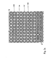
- the Fig. 1c shows in a plan view and a schematic perspective view of the support structure 25 according to the Fig. 1a ,
- the Fig. 1d shows a further variant of the support structure according to the Fig. 1c
- edges 150 of the plate-shaped carrier 134 can be folded away in order to further reduce the base area of the carrier 134, for example when it is to be transferred with the containers to a cramped further processing station, for example to a freeze-drying cabinet with a limited base area.
- the edges 150 are connected to the carrier 134 via hinges 151.
- On top of the carrier 134 and the Edges 150 are provided at mutually corresponding positions block-shaped stops 153 which define a coplanar alignment of the edges 150 and the carrier 134 in the mutual stop.
- the edges 150 can also be removed from the carrier 134.
- the edges 150 may of course be provided along all four longitudinal sides of the carrier 134.
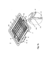
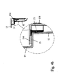
- FIGS. 2a to 2d show a support structure or support 134 according to the present invention (also referred to in the art as a "nest").
- a plurality of annular receptacles are formed in a regular arrangement, which are formed by annular side walls 163, whose inner diameter can be matched to the outer diameter of the container to be accommodated therein.
- the bottoms of the containers are supported directly on top of the carrier 134, the side walls 163 reliably preventing contact from adjacent containers.
- the recordings can clamp the lower ends of the container 2.
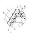
- a greatly enlarged section of the Fig. 2c project from the underside of the carrier hook-shaped latching hooks 160 which are arranged around the openings 135 of the carrier 134 around.
- the container 2 can be inserted from below the carrier 134 forth in the latching hooks 160 until the upper edge 6 of the container is engaged behind the form-fitting latching hook 160.
- the containers are stored reliably, wherein all bottoms of the container 2 are arranged at the same height level and a contact of adjacent containers is prevented.
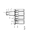
- the latching hooks 160 are sufficiently elastic, so that the container 2 can also be removed therefrom again under elastic deformation. How to get the Fig. 2b and 2c can take several layers of such carriers 134 can be stacked with the containers fixed thereto.
- the locking hooks 160 have a lower insertion bevel 160a.
- the container 2 from the underside of the carrier ago finally reaches the upper edge 6 of the container 2 in abutment with the lower insertion bevel 160 a.
- the carrier of the upper edge 6 of the container slides along the lower insertion bevel 160a, so that the latching hooks are elastically pivoted radially outward and are spread apart.
- the bottom edge slides of the upper edge 6 of the container 2 see. Fig.
- the latching hooks 160 return to their initial position, in which the containers 2 in the region of the neck portion 5, in particular below the upper edge 6, can be kept clamped by the latching hooks 160.
- the underside of the upper edge 6 of the container can also rest loosely on the obliquely downwardly inclined support surface 160b of the latching hooks, ie with a certain radial play. How to get the Fig. 2d can remove, the inclination of the obliquely downward inclined support surface 160b facilitates removal of the container 2 from the carrier.
- the containers are arranged upright and with their open end towards the upper end of the transport and packaging container
- the containers can in principle also be turned, i. with its open end pointing to the bottom of the transport and packaging container, be arranged.
- the Fig. 3 shows a packaging unit which is formed by a transport container 12 open on both sides and a support structure 165 (which is not formed according to the invention) formed therein and which on the top and bottom by means of a protective or protective or glued to the edge 15 of the transport container 12
- Packaging film 130 is closed.
- the protective film 130 can in particular be a gas-permeable plastic film, in particular a braid made of synthetic fibers, for example of polypropylene fibers (PP) or also a Tyvek® protective film, which sterilizes the containers received and packed in the holding structure 25 2 through the film 130 therethrough.
- the transport container 12 may be formed open only at one end, such as the type of transport and packaging container 10, as shown schematically in the Fig. 1a is shown.
- antimicrobial powders may be added to the plastic of the support structure (of the carrier) and / or of the transport and packaging container.
- Antimicrobial acting powders for example with Ag, Zn, Cu, Ce, Te or I atoms or ions, are due to their biocidal, bacteriocidal, and fungicidal Effect as an additive or filler suitable for a variety of purposes.
- the biocidal effect occurs for example against bacilli, fungi, viruses, yeasts, algae and other microorganisms.
- glass powders containing Ag 2 O, CuO, Cu 2 O, TeO 2 , ZnO, CeO 2 and I can also be added to the plastic of the support structure (of the support) and / or the transport and packaging container.
- the mechanical and optical properties remain largely unchanged.
- the introduction of the powders can either be incorporated as nanopowders, for example, the plastic powder mixtures in injection molding or in paints in deep drawing processes.
- An antimicrobial effect can also be achieved if the plastic is provided with an antimicrobial coating containing the aforementioned powders.
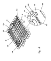
- the Fig. 4a and 4b show a further embodiment variant for a packaging unit 1 with a recorded in the transport and packaging container 10 holding plate 134, which is not according to the invention formed and in which a plurality of containers 2 are fixed by means of ring elements 137 form-fitting manner.
- the packaging unit 1 has provisions for identification and / or tracking as follows: As shown in the enlarged insert of FIG.
- an electronically wireless (wireless) readable RFID chip or RuBee chip 175 arranged (a RuBee chip sparks on frequencies that can penetrate metal and water), which can be read out without contact through the side walls of the packaging unit 1 and query information regarding the identity, important product characteristics (manufacturer, content, date of manufacture, expiration date, ...) etc. issues.
- the chip 175 may be glued into the packaging unit 1 at a suitable location, also elsewhere than shown in the figure.
- the chip 175 may be arranged so that in the case of opening the packaging unit 1 or removing the holding plate 134 from the packaging unit 1 out the chip 175 is destroyed, for example, is torn or disabled. Due to the lack of response of the chip 175 to a radio interrogation, information is thus available which indicates that the packaging unit has been manipulated in some way since the previous packaging. Because the chip 175 does not respond to the radio query. This can serve, for example, to prove the authenticity and integrity of the packaging unit and the containers accommodated therein.
- the holding force exerted on the containers by the form-locking holding means is sufficient to reliably hold the containers to the holding structure.
- the holding force exerted is greater than the weight of the container, possibly with content and plugs.
- the holding force can also be dimensioned by suitable design of the holding means so that it is greater than usual forces in the handling, processing or treatment of the container in a process plant. As a result, a reliable mounting of the container is always guaranteed. Nevertheless, you can the container according to preferred further embodiments of the invention are adjusted against this holding force in the openings or receptacles, in particular axially advanced or rotated. The force required for this must only be greater than the force exerted by the holding means.
- the support structure in the context of the present invention also be formed of a thermoplastic, thermosetting or elastomeric plastic, at least portions of the support structure and the carrier are provided with a reibredumpden coating to facilitate the insertion and removal of the container ,
- the holding structure and / or the transport container, or portions thereof be formed of a fiber-reinforced plastics or a plastic, which are added to increase its thermal conductivity ceramics or metals added.
- fiber-reinforced plastics have a higher thermal conductivity of up to 0.9 W / (K m) for carbon fibers. If ceramics or metals are added to the plastics, the thermal conductivity is further increased. The result is the so-called thermally conductive plastics. This achieves a thermal conductivity of 20 W / (K m).
Landscapes
- Health & Medical Sciences (AREA)
- Life Sciences & Earth Sciences (AREA)
- Veterinary Medicine (AREA)
- Public Health (AREA)
- General Health & Medical Sciences (AREA)
- Animal Behavior & Ethology (AREA)
- Vascular Medicine (AREA)
- Biomedical Technology (AREA)
- Heart & Thoracic Surgery (AREA)
- Hematology (AREA)
- Anesthesiology (AREA)
- Engineering & Computer Science (AREA)
- Chemical Kinetics & Catalysis (AREA)
- Chemical & Material Sciences (AREA)
- Clinical Laboratory Science (AREA)
- Pharmacology & Pharmacy (AREA)
- Packages (AREA)
- Medical Preparation Storing Or Oral Administration Devices (AREA)
Claims (15)
- Structure de support pour le support simultané d'une pluralité de récipients (2) pour des substances d'application médicale, pharmaceutique ou cosmétique, comportant un support plan rectangulaire (134) ayant une pluralité d'ouvertures (39) disposées suivant une configuration plane régulière et des éléments de maintien (160) associés pour le maintien direct de la pluralité de récipients (2) sur le support (134), caractérisé en ce que les éléments de maintien font saillie depuis une face inférieure du support et sont adaptés pour le maintien direct des récipients (2) au niveau de leur bord supérieur, et en ce que des réceptacles sont disposés sur une face supérieure du support, opposée à la face inférieure, et adaptés pour le logement des récipients (2) au niveau de la face supérieure du support.
- La structure de support de la revendication 1, dans laquelle les récipients sont conçus de telle sorte que les fonds (3) des récipients sont supportés directement sur la surface supérieure du support.
- La structure de support de la revendication 1 ou 2, dans laquelle les réceptacles sont formées par des parois circulaires (163), présentant des diamètres internes correspondant au diamètre externe des récipients devant y être logés.
- La structure de support de l'une quelconque des revendications précédentes, dans laquelle les éléments de maintien sont formés sous forme de crochets de verrouillage élastiques (160), faisant saillie depuis la face inférieure du support (134) et disposés autour des ouvertures du support (134).
- La structure de support de la revendication 4, dans laquelle les crochets de verrouillage (160) présentent une forme adaptée au bord supérieur des récipients (2) pour en permettre le verrouillage direct.
- La structure de support de la revendication 4 ou 5, dans laquelle les crochets de verrouillage (160) ont un biseau d'insertion inférieur.
- La structure de support de la revendication 5 ou 6, dans laquelle les crochets de verrouillage (160) comporte en outre un biseau faisant face à l'ouverture respective du support (134) et sur lequel est maintenu le bord supérieur du récipient (2) fixé.
- La structure de support de l'une des revendications 4 à 7, dans laquelle les crochets de verrouillage (160) sont de fabrication avec le support (134).
- La structure de support de l'une quelconque des revendications précédentes, dans laquelle des bandes ou des parois latérales sont disposées entre les ouvertures du support (134) de manière à empêcher tout contact direct entre des récipients adjacents maintenus par le support.
- La structure de support de l'une quelconque des revendications 4 ou 5, dans laquelle des éléments de bord (68) du support (134) sont amovibles ou peuvent pivoter dans le but de réduire la surface de base de la structure de support dans son ensemble.
- La structure de support de l'une quelconque des revendications précédentes, dans laquelle les éléments de maintien sont conçus de façon à ce que restent accessible depuis la face inférieure du support au moins une majeure partie des fonds (3) ou des extrémités inférieures des récipients, et en ce que les récipients (2) sont maintenus sur le support (25) de telle manière que tous les fonds ou les extrémités inférieures des récipients sont disposés à la même distance de la face supérieure du support (25) ou peuvent être disposés de cette manière pour présenter une surface plane.
- La structure de support de l'une quelconque des revendications précédentes, réalisée au moins à partir d'un matériau thermoplastique antimicrobien, d'un matériau plastique thermodurcissable ou élastomère, avec ajout d'une poudre antimicrobienne ou d'une poudre de verre, dans laquelle la poudre antimicrobienne ou la poudre de verre est ajoutée à la matière plastique, exclusivement ou principalement, dans les parties du matériau plastique proche de la surface.
- Un récipient de transport ou d'emballage pour une pluralité de récipients (2) pour des substances d'application médicale ou pharmaceutique, comprenant un récipient en forme de boîte (10), caractérisé par une structure de support (25) logée dans le récipient en forme de boîte (10), pour le support simultané de la pluralité de containers, telle que définie dans l'une quelconque des revendications précédentes.
- Le récipient de transport ou d'emballage de la revendication 13, comprenant en outre un film protecteur ou d'emballage (130), soudé sur un bord supérieur (15) du récipient en forme de boîte (10), et des moyens d'identification ou de suivi (175) pour l'identification ou le suivi du récipient de transport ou d'emballage ou du support (25) avec les récipients qui y sont logés, dans lequel les moyens d'identification ou de suivi (175) sont connectés avec la structure de support (25° et/ou le récipient de transport ou d'emballage (1) et/ou le film protecteur ou d'emballage (130) de telle manière que les moyens d'identification ou de suivi (175) sont détruits lors de l'ouverture du récipient de transport ou d'emballage (1) ou lors de l'enlèvement ou la dépose de la structure de support (25) ou des récipients (2) qui y sont logés.
- Le récipient de transport ou d'emballage de la revendication 14, dans lequel les moyens d'identification ou de suivi (175) consistent en une puce RFID ou une puce RuBee pour la lecture d'informations sans fil, dans lequel au moins un capteur est disposés pour un suivi daté des paramètres de transport ou d'emballage du récipient, ou leur suivi et enregistrement de manière datée.
Priority Applications (1)
| Application Number | Priority Date | Filing Date | Title |
|---|---|---|---|
| EP14158368.2A EP2740537A1 (fr) | 2012-05-03 | 2013-05-03 | Structure de support pour le support simultané d'une pluralité de récipients pour la conservation de substances pour des applications médicales, pharmaceutiques ou cosmétiques ainsi que récipient de transport ou d'emballage doté de celle-ci |
Applications Claiming Priority (2)
| Application Number | Priority Date | Filing Date | Title |
|---|---|---|---|
| US201261642154P | 2012-05-03 | 2012-05-03 | |
| DE102012103898A DE102012103898A1 (de) | 2012-05-03 | 2012-05-03 | Haltestruktur zum gleichzeitigen Halten einer Mehrzahl von medizinischen oder pharmazeutischen Behältern sowie Transport- oder Verpackungsbehälter mit Selbiger |
Related Child Applications (2)
| Application Number | Title | Priority Date | Filing Date |
|---|---|---|---|
| EP14158368.2A Division-Into EP2740537A1 (fr) | 2012-05-03 | 2013-05-03 | Structure de support pour le support simultané d'une pluralité de récipients pour la conservation de substances pour des applications médicales, pharmaceutiques ou cosmétiques ainsi que récipient de transport ou d'emballage doté de celle-ci |
| EP14158368.2A Division EP2740537A1 (fr) | 2012-05-03 | 2013-05-03 | Structure de support pour le support simultané d'une pluralité de récipients pour la conservation de substances pour des applications médicales, pharmaceutiques ou cosmétiques ainsi que récipient de transport ou d'emballage doté de celle-ci |
Publications (2)
| Publication Number | Publication Date |
|---|---|
| EP2659980A1 EP2659980A1 (fr) | 2013-11-06 |
| EP2659980B1 true EP2659980B1 (fr) | 2015-07-01 |
Family
ID=48236733
Family Applications (2)
| Application Number | Title | Priority Date | Filing Date |
|---|---|---|---|
| EP13166538.2A Active EP2659980B1 (fr) | 2012-05-03 | 2013-05-03 | Structure de support pour le support simultané d'une pluralité de récipients médicaux ou pharmaceutiques ainsi que récipient de transport ou d'emballage doté d'une telle structure |
| EP14158368.2A Withdrawn EP2740537A1 (fr) | 2012-05-03 | 2013-05-03 | Structure de support pour le support simultané d'une pluralité de récipients pour la conservation de substances pour des applications médicales, pharmaceutiques ou cosmétiques ainsi que récipient de transport ou d'emballage doté de celle-ci |
Family Applications After (1)
| Application Number | Title | Priority Date | Filing Date |
|---|---|---|---|
| EP14158368.2A Withdrawn EP2740537A1 (fr) | 2012-05-03 | 2013-05-03 | Structure de support pour le support simultané d'une pluralité de récipients pour la conservation de substances pour des applications médicales, pharmaceutiques ou cosmétiques ainsi que récipient de transport ou d'emballage doté de celle-ci |
Country Status (3)
| Country | Link |
|---|---|
| US (1) | US20140027332A1 (fr) |
| EP (2) | EP2659980B1 (fr) |
| DE (2) | DE102012103898A1 (fr) |
Cited By (1)
| Publication number | Priority date | Publication date | Assignee | Title |
|---|---|---|---|---|
| EP3851088B1 (fr) * | 2020-01-16 | 2023-08-16 | SCHOTT Pharma AG & Co. KGaA | Procédé de traitement de récipients en verre, dispositif de capture et de maintien de récipients en verre et appareil de traitement de récipients en verre |
Families Citing this family (24)
| Publication number | Priority date | Publication date | Assignee | Title |
|---|---|---|---|---|
| TW201900138A (zh) * | 2013-08-16 | 2019-01-01 | 加拿大商凡爾克斯醫藥系統公司 | 用於裝填藥物容器的方法 |
| US12515832B2 (en) * | 2013-08-16 | 2026-01-06 | Vanrx Pharmasystems Inc. | Method, device and system for filling pharmaceutical containers |
| HUE044371T2 (hu) * | 2015-04-17 | 2019-10-28 | Schott Kaisha Pvt Ltd | Hordozószerkezet lezárt patronokhoz, szállító- vagy csomagolási konténer, valamint eljárás |
| EP3413951B1 (fr) * | 2016-02-08 | 2020-05-06 | West Pharmaceutical Services, Inc. | Module alvéolaire |
| DE102016103404A1 (de) | 2016-02-26 | 2017-08-31 | Schott Ag | Verfahren zum Überführen einer Mehrzahl von Behältern zur Aufbewahrung von Substanzen für medizinische, pharmazeutische oder kosmetische Zwecke in einen Reinraum, Transport- und Verpackungsbehälter und Verpackungsgebilde hierfür sowie Verwendung |
| DE102016121086A1 (de) * | 2016-11-04 | 2018-05-09 | Schott Schweiz Ag | Haltestruktur zum Halten einer Mehrzahl von Behältern für pharmazeutische, medizinische oder kosmetische Zwecke sowie Transport- oder Verpackungsbehälter mit selbiger |
| DE102016123147A1 (de) * | 2016-11-30 | 2018-05-30 | Schott Ag | Haltestruktur zum gleichzeitigen Halten einer Mehrzahl von Vials, Verwendung hiervon sowie Verfahren zur Behandlung solcher Vials |
| DE202016107209U1 (de) | 2016-12-21 | 2018-05-03 | Schott Schweiz Ag | Haltestruktur zum gleichzeitigen Halten einer Mehrzahl von Behältern für Substanzen für pharmazeutische, medizinische oder kosmetische Anwendungen, Transportgebilde und Transport- oder Verpackungsbehälter mit selbiger |
| DE102017101398A1 (de) | 2017-01-25 | 2018-07-26 | Schott Schweiz Ag | Haltestruktur zum gleichzeitigen Halten einer Mehrzahl von Behältern für Substanzen für pharmazeutische, medizinische oder kosmetische Anwendungen, Transportgebilde und Transport- oder Verpackungsbehälter mit selbiger |
| US10578890B1 (en) * | 2017-10-18 | 2020-03-03 | William Cheslock | Apparatus for storing, preserving and cleaning contact lenses |
| ES3069718T3 (en) | 2017-11-03 | 2026-06-10 | Amgen Inc | System and approaches for sterilizing a drug delivery device |
| JP7221287B2 (ja) * | 2017-11-08 | 2023-02-13 | ウィンドギャップ メディカル, インコーポレイテッド | 自動注入器を提供しアセンブリするためのシステム及び方法 |
| US11591137B2 (en) | 2017-12-14 | 2023-02-28 | Philip Morris Products S.A. | Child resistant container |
| ES2982563T3 (es) * | 2018-05-02 | 2024-10-16 | Becton Dickinson France | Dispositivo de sujeción para soportar una pluralidad de contenedores médicos, paquete de contenedores médicos que comprende este dispositivo de sujeción, y método para fabricar un contenedor médico |
| FR3087116B1 (fr) * | 2018-10-10 | 2024-06-21 | Crossject | Dispositif pour le maintien de tubes de dispositif d’injection |
| IT201900011982A1 (it) * | 2019-07-17 | 2021-01-17 | Nuova Ompi Srl | Struttura per il confezionamento di contenitori primari ad uso farmaceutico |
| EP3791906B1 (fr) | 2019-09-11 | 2024-03-27 | SCHOTT Pharma Schweiz AG | Dispositif de charge doté d'un moyen de positionnement et d'un procédé de fermeture de récipients à ventilation |
| EP3798142B1 (fr) * | 2019-09-25 | 2024-05-01 | SCHOTT Pharma AG & Co. KGaA | Dispositif de support des récipients |
| DE102020126552A1 (de) | 2020-10-09 | 2022-04-14 | Syntegon Technology Gmbh | Nestausheber und Sterilkammer |
| US12286270B2 (en) * | 2021-05-18 | 2025-04-29 | Gerresheimer Glas Gmbh | Transporting packaging units |
| EP4516335A1 (fr) * | 2023-08-29 | 2025-03-05 | Becton Dickinson France | Système d'emballage pour transporter des dispositifs médicaux et procédé de formation d'un tel système d'emballage |
| CN121300643A (zh) * | 2024-07-08 | 2026-01-09 | 瑞马科宝股份有限公司 | 捕获对象弯曲机制 |
| EP4717286A1 (fr) * | 2024-09-25 | 2026-04-01 | SCHOTT Pharma Schweiz AG | Nid avec ouvertures de levage et de centrage limités de ce nid |
| CN119329889A (zh) * | 2024-10-31 | 2025-01-21 | 江苏乐聚医药科技有限公司 | 一种巢板 |
Family Cites Families (28)
| Publication number | Priority date | Publication date | Assignee | Title |
|---|---|---|---|---|
| US3199908A (en) * | 1959-07-17 | 1965-08-10 | Illinois Tool Works | Container carrier and package |
| US2979210A (en) * | 1960-04-19 | 1961-04-11 | Arthur H Thomas Company | Test tube rack |
| US3317087A (en) * | 1964-09-25 | 1967-05-02 | Landis Plastics Inc | Holder for flanged parts |
| US3297191A (en) * | 1965-04-12 | 1967-01-10 | Watson S Eastman | Molded shipping container |
| DE7307208U (de) * | 1973-02-24 | 1973-05-24 | Original Hanau Quarzlampen | Ampullenhalter |
| US4120396A (en) * | 1977-08-16 | 1978-10-17 | The Continental Group, Inc. | Reusable can carrier with can enlocking means on opposite surfaces |
| DE4303501A1 (de) * | 1993-02-06 | 1994-08-11 | Hans Schwartz | Haltevorrichtung |
| US6132684A (en) * | 1997-10-31 | 2000-10-17 | Becton Dickinson And Company | Sample tube holder |
| US6164044A (en) * | 1998-03-13 | 2000-12-26 | Becton Dickinson And Company | Method and apparatus for assembling and packaging medical devices |
| US6059099A (en) * | 1998-09-18 | 2000-05-09 | Eco-Pak Products, Inc. | Multi-pack carrier |
| DE10012575A1 (de) * | 2000-03-15 | 2001-09-27 | Schott Glas | Transportvorrichtung für medizinische Behälter |
| AU2002314050A1 (en) * | 2002-05-06 | 2003-11-17 | Peter Ivan Sygall | Processing samples of liquid material |
| DE20310332U1 (de) * | 2003-07-04 | 2004-11-11 | Mwg-Biotech Ag | Vorrichtung zum automatischen Öffnen und Schließen von Reaktionsgefäßen |
| US7448493B2 (en) * | 2003-12-18 | 2008-11-11 | Rehrig Pacific Company | Bottle carrier |
| US7404486B2 (en) * | 2003-12-29 | 2008-07-29 | Matthew Charles Smithers | Modular beverage can interlocking device |
| US8100263B2 (en) | 2004-07-01 | 2012-01-24 | West Pharmaceutical Services, Inc. | Vacuum package system |
| US20060108319A1 (en) * | 2004-11-24 | 2006-05-25 | Meittunen Eric J | Vial attachment to prevent needle sticks |
| US8118167B2 (en) | 2007-03-05 | 2012-02-21 | Daikyo Seiko, Ltd. | Medical container |
| CH702317B1 (it) | 2007-08-02 | 2011-06-15 | Stevanato Group Internat As | Struttura di confezione di flaconi in vetro ad uso farmaceutico. |
| EP2098296A1 (fr) * | 2008-02-25 | 2009-09-09 | F. Hoffmann-La Roche AG | Portoir de tube d'échantillons, ensemble de positionnement de tube d'échantillons comportant un tel portoir, et analyseur comportant un tel assemblage |
| CN102057268B (zh) * | 2008-06-06 | 2012-05-09 | 卡皮托塑料制品有限责任公司 | 带有小瓶的瓶架 |
| EP2389247B1 (fr) * | 2009-01-23 | 2017-03-01 | Biotix, Inc. | Plateaux d'embout de pipette antistatiques |
| IT1393082B1 (it) | 2009-01-27 | 2012-04-11 | Semafra S A | Struttura di imballo di contenitori ad uso farmaceutico |
| CN102481403B (zh) | 2009-08-07 | 2014-06-04 | 贝克顿迪金森法国公司 | 用于放置细长物体、特别是注射器本体或注射器的盘子 |
| IT1399750B1 (it) | 2010-04-30 | 2013-05-03 | Stevanato Group Internat As | Struttura di imballaggio per contenitori ad uso farmaceutico |
| CN103118945A (zh) | 2010-07-16 | 2013-05-22 | 斯泰瓦纳托集团国际有限公司 | 用于注射剂包装的制造方法 |
| DK2609019T3 (en) | 2010-08-27 | 2015-05-26 | Sanofi Aventis Deutschland | PACKAGING SYSTEM FOR MEDICAL MULTI-COMPONENT PRODUCTS |
| US20120051986A1 (en) * | 2010-08-31 | 2012-03-01 | Wheaton Industries, Inc. | Rack configured to support vials with identification indicia exposed |
-
2012
- 2012-05-03 DE DE102012103898A patent/DE102012103898A1/de not_active Withdrawn
-
2013
- 2013-05-03 US US13/886,717 patent/US20140027332A1/en not_active Abandoned
- 2013-05-03 EP EP13166538.2A patent/EP2659980B1/fr active Active
- 2013-05-03 DE DE202013012689.2U patent/DE202013012689U1/de not_active Expired - Lifetime
- 2013-05-03 EP EP14158368.2A patent/EP2740537A1/fr not_active Withdrawn
Cited By (1)
| Publication number | Priority date | Publication date | Assignee | Title |
|---|---|---|---|---|
| EP3851088B1 (fr) * | 2020-01-16 | 2023-08-16 | SCHOTT Pharma AG & Co. KGaA | Procédé de traitement de récipients en verre, dispositif de capture et de maintien de récipients en verre et appareil de traitement de récipients en verre |
Also Published As
| Publication number | Publication date |
|---|---|
| DE102012103898A1 (de) | 2013-11-07 |
| US20140027332A1 (en) | 2014-01-30 |
| EP2659980A1 (fr) | 2013-11-06 |
| DE202013012689U1 (de) | 2018-07-04 |
| EP2740537A1 (fr) | 2014-06-11 |
Similar Documents
| Publication | Publication Date | Title |
|---|---|---|
| EP2659979B1 (fr) | Structure de support portant simultanément une pluralité de récipients pour des applications médicales, pharmaceutiques ou cosmétiques ainsi que récipient de transport ou d'emballage | |
| DE202013012689U1 (de) | Haltestruktur zum gleichzeitigen Halten einer Mehrzahl von Behältern zur Aufbewahrung von Substanzen für medizinische, pharmazeutische oder kosmetische Anwendungen sowie Transport- oder Verpackungsbehälter und Kombination mit Selbiger | |
| EP2659922B1 (fr) | Structure de support pour le support simultané d'une pluralité de récipients médicaux ou pharmaceutiques ainsi que récipient de transport ou d'emballage doté d'une telle structure | |
| EP2862809B1 (fr) | Structure de support de récipients pour substances destinées aux applications médicales, pharmaceutiques ou cosmétiques ainsi que récipient de transport ou d'emballage en étant équipé | |
| EP2872843B1 (fr) | Structure de retenue permettant de retenir simultanément une pluralité de récipients pour des substances destinées à des applications médicales, pharmaceutiques ou cosmétiques, et récipients de transport ou d'emballage contenant lesdites substances | |
| EP2844936B1 (fr) | Procédé et dispositif pour manipuler des récipients et des substances contenues dans ces récipients pour des applications médicales, pharmaceutiques ou cosmétiques | |
| DE102013112167A1 (de) | Haltestruktur zum gleichzeitigen Halten einer Mehrzahl von Behältern für Substanzen für medizinische, pharmazeutische oder kosmetische Anwendungen sowie Transport- und Verpackungsbehälter mit Selbiger sowie Verfahren | |
| DE102012103899B4 (de) | Verfahren und Vorrichtung zur Behandlung von Behältern zur Aufbewahrung von Substanzen für medizinische oder pharmazeutische Anwendungen | |
| EP2916885B1 (fr) | Dispositif et procédé destinés au traitement ou manipulation des récipients pour les substances pour les applications médicales, pharmaceutiques ou cosmétiques | |
| DE102013114896B4 (de) | Verpackungsstruktur und Verfahren zur sterilen Verpackung von Behältern für Substanzen für medizinische, pharmazeutische oder kosmetische Anwendungen sowie Verfahren zur Weiterverarbeitung von Behältern unter Verwendung der Verpackungsstruktur | |
| DE102012110339B4 (de) | Haltestruktur zum gleichzeitigen Halten einer Mehrzahl von medizinischen oder pharmazeutischen Behältern sowie Transport- oder Verpackungsbehälter mit Selbiger und Verfahren zur Behandlung solcher Behälter | |
| DE102013114404A1 (de) | Transport- und Verpackungsbehälter mit einer Haltestruktur zum gleichzeitigen Halten einer Mehrzahl von Behältern für medizinische, pharmazeutische oder kosmetische Anwendungen sowie Verfahren und Verwendungen hiervon | |
| DE102016123147A1 (de) | Haltestruktur zum gleichzeitigen Halten einer Mehrzahl von Vials, Verwendung hiervon sowie Verfahren zur Behandlung solcher Vials | |
| EP3534986A1 (fr) | Structure de retenue servant à retenir simultanément une pluralité de contenants pour substances à usage pharmaceutique, médical ou cosmétique, structure de transport et contenant de transport ou d'emballage la comportant | |
| DE10012575A1 (de) | Transportvorrichtung für medizinische Behälter | |
| DE102012108215A1 (de) | Haltestruktur zum gleichzeitigen Halten einer Mehrzahl von Behältern für Substanzen für medizinische, pharmazeutische oder kosmetische Anwendungen sowie Transport- oder Verpackungsbehälter mit selbiger | |
| DE102012110973B4 (de) | Verwendung eines Halteelements zum Halten eines Behälters, sowie Haltestruktur | |
| EP2659981B1 (fr) | Récipient de transport ou d'emballage avec structure de support pour le support simultané d'une pluralité de récipients pour des applications médicales, pharmaceutiques ou cosmétiques et procédé de traitement de tels récipients |
Legal Events
| Date | Code | Title | Description |
|---|---|---|---|
| PUAI | Public reference made under article 153(3) epc to a published international application that has entered the european phase |
Free format text: ORIGINAL CODE: 0009012 |
|
| 17P | Request for examination filed |
Effective date: 20130506 |
|
| AK | Designated contracting states |
Kind code of ref document: A1 Designated state(s): AL AT BE BG CH CY CZ DE DK EE ES FI FR GB GR HR HU IE IS IT LI LT LU LV MC MK MT NL NO PL PT RO RS SE SI SK SM TR |
|
| AX | Request for extension of the european patent |
Extension state: BA ME |
|
| RBV | Designated contracting states (corrected) |
Designated state(s): AL AT BE BG CH CY CZ DE DK EE ES FI FR GB GR HR HU IE IS IT LI LT LU LV MC MK MT NL NO PL PT RO RS SE SI SK SM TR |
|
| GRAP | Despatch of communication of intention to grant a patent |
Free format text: ORIGINAL CODE: EPIDOSNIGR1 |
|
| INTG | Intention to grant announced |
Effective date: 20150310 |
|
| GRAS | Grant fee paid |
Free format text: ORIGINAL CODE: EPIDOSNIGR3 |
|
| GRAA | (expected) grant |
Free format text: ORIGINAL CODE: 0009210 |
|
| AK | Designated contracting states |
Kind code of ref document: B1 Designated state(s): AL AT BE BG CH CY CZ DE DK EE ES FI FR GB GR HR HU IE IS IT LI LT LU LV MC MK MT NL NO PL PT RO RS SE SI SK SM TR |
|
| REG | Reference to a national code |
Ref country code: GB Ref legal event code: FG4D Free format text: NOT ENGLISH |
|
| REG | Reference to a national code |
Ref country code: AT Ref legal event code: REF Ref document number: 733620 Country of ref document: AT Kind code of ref document: T Effective date: 20150715 Ref country code: CH Ref legal event code: EP |
|
| REG | Reference to a national code |
Ref country code: IE Ref legal event code: FG4D Free format text: LANGUAGE OF EP DOCUMENT: GERMAN |
|
| REG | Reference to a national code |
Ref country code: DE Ref legal event code: R096 Ref document number: 502013000798 Country of ref document: DE |
|
| REG | Reference to a national code |
Ref country code: NL Ref legal event code: MP Effective date: 20150701 |
|
| REG | Reference to a national code |
Ref country code: LT Ref legal event code: MG4D |
|
| PG25 | Lapsed in a contracting state [announced via postgrant information from national office to epo] |
Ref country code: FI Free format text: LAPSE BECAUSE OF FAILURE TO SUBMIT A TRANSLATION OF THE DESCRIPTION OR TO PAY THE FEE WITHIN THE PRESCRIBED TIME-LIMIT Effective date: 20150701 Ref country code: LV Free format text: LAPSE BECAUSE OF FAILURE TO SUBMIT A TRANSLATION OF THE DESCRIPTION OR TO PAY THE FEE WITHIN THE PRESCRIBED TIME-LIMIT Effective date: 20150701 Ref country code: NO Free format text: LAPSE BECAUSE OF FAILURE TO SUBMIT A TRANSLATION OF THE DESCRIPTION OR TO PAY THE FEE WITHIN THE PRESCRIBED TIME-LIMIT Effective date: 20151001 Ref country code: LT Free format text: LAPSE BECAUSE OF FAILURE TO SUBMIT A TRANSLATION OF THE DESCRIPTION OR TO PAY THE FEE WITHIN THE PRESCRIBED TIME-LIMIT Effective date: 20150701 Ref country code: GR Free format text: LAPSE BECAUSE OF FAILURE TO SUBMIT A TRANSLATION OF THE DESCRIPTION OR TO PAY THE FEE WITHIN THE PRESCRIBED TIME-LIMIT Effective date: 20151002 |
|
| PG25 | Lapsed in a contracting state [announced via postgrant information from national office to epo] |
Ref country code: RS Free format text: LAPSE BECAUSE OF FAILURE TO SUBMIT A TRANSLATION OF THE DESCRIPTION OR TO PAY THE FEE WITHIN THE PRESCRIBED TIME-LIMIT Effective date: 20150701 Ref country code: IS Free format text: LAPSE BECAUSE OF FAILURE TO SUBMIT A TRANSLATION OF THE DESCRIPTION OR TO PAY THE FEE WITHIN THE PRESCRIBED TIME-LIMIT Effective date: 20151101 Ref country code: PL Free format text: LAPSE BECAUSE OF FAILURE TO SUBMIT A TRANSLATION OF THE DESCRIPTION OR TO PAY THE FEE WITHIN THE PRESCRIBED TIME-LIMIT Effective date: 20150701 Ref country code: ES Free format text: LAPSE BECAUSE OF FAILURE TO SUBMIT A TRANSLATION OF THE DESCRIPTION OR TO PAY THE FEE WITHIN THE PRESCRIBED TIME-LIMIT Effective date: 20150701 Ref country code: HR Free format text: LAPSE BECAUSE OF FAILURE TO SUBMIT A TRANSLATION OF THE DESCRIPTION OR TO PAY THE FEE WITHIN THE PRESCRIBED TIME-LIMIT Effective date: 20150701 Ref country code: PT Free format text: LAPSE BECAUSE OF FAILURE TO SUBMIT A TRANSLATION OF THE DESCRIPTION OR TO PAY THE FEE WITHIN THE PRESCRIBED TIME-LIMIT Effective date: 20151102 Ref country code: SE Free format text: LAPSE BECAUSE OF FAILURE TO SUBMIT A TRANSLATION OF THE DESCRIPTION OR TO PAY THE FEE WITHIN THE PRESCRIBED TIME-LIMIT Effective date: 20150701 |
|
| REG | Reference to a national code |
Ref country code: DE Ref legal event code: R097 Ref document number: 502013000798 Country of ref document: DE |
|
| PG25 | Lapsed in a contracting state [announced via postgrant information from national office to epo] |
Ref country code: CZ Free format text: LAPSE BECAUSE OF FAILURE TO SUBMIT A TRANSLATION OF THE DESCRIPTION OR TO PAY THE FEE WITHIN THE PRESCRIBED TIME-LIMIT Effective date: 20150701 Ref country code: DK Free format text: LAPSE BECAUSE OF FAILURE TO SUBMIT A TRANSLATION OF THE DESCRIPTION OR TO PAY THE FEE WITHIN THE PRESCRIBED TIME-LIMIT Effective date: 20150701 Ref country code: SK Free format text: LAPSE BECAUSE OF FAILURE TO SUBMIT A TRANSLATION OF THE DESCRIPTION OR TO PAY THE FEE WITHIN THE PRESCRIBED TIME-LIMIT Effective date: 20150701 Ref country code: EE Free format text: LAPSE BECAUSE OF FAILURE TO SUBMIT A TRANSLATION OF THE DESCRIPTION OR TO PAY THE FEE WITHIN THE PRESCRIBED TIME-LIMIT Effective date: 20150701 |
|
| PLBE | No opposition filed within time limit |
Free format text: ORIGINAL CODE: 0009261 |
|
| STAA | Information on the status of an ep patent application or granted ep patent |
Free format text: STATUS: NO OPPOSITION FILED WITHIN TIME LIMIT |
|
| REG | Reference to a national code |
Ref country code: FR Ref legal event code: PLFP Year of fee payment: 4 |
|
| PG25 | Lapsed in a contracting state [announced via postgrant information from national office to epo] |
Ref country code: RO Free format text: LAPSE BECAUSE OF FAILURE TO SUBMIT A TRANSLATION OF THE DESCRIPTION OR TO PAY THE FEE WITHIN THE PRESCRIBED TIME-LIMIT Effective date: 20150701 |
|
| 26N | No opposition filed |
Effective date: 20160404 |
|
| PG25 | Lapsed in a contracting state [announced via postgrant information from national office to epo] |
Ref country code: BE Free format text: LAPSE BECAUSE OF NON-PAYMENT OF DUE FEES Effective date: 20160531 Ref country code: SI Free format text: LAPSE BECAUSE OF FAILURE TO SUBMIT A TRANSLATION OF THE DESCRIPTION OR TO PAY THE FEE WITHIN THE PRESCRIBED TIME-LIMIT Effective date: 20150701 |
|
| PG25 | Lapsed in a contracting state [announced via postgrant information from national office to epo] |
Ref country code: LU Free format text: LAPSE BECAUSE OF FAILURE TO SUBMIT A TRANSLATION OF THE DESCRIPTION OR TO PAY THE FEE WITHIN THE PRESCRIBED TIME-LIMIT Effective date: 20160503 |
|
| REG | Reference to a national code |
Ref country code: IE Ref legal event code: MM4A |
|
| REG | Reference to a national code |
Ref country code: FR Ref legal event code: PLFP Year of fee payment: 5 |
|
| PG25 | Lapsed in a contracting state [announced via postgrant information from national office to epo] |
Ref country code: IE Free format text: LAPSE BECAUSE OF NON-PAYMENT OF DUE FEES Effective date: 20160503 |
|
| PG25 | Lapsed in a contracting state [announced via postgrant information from national office to epo] |
Ref country code: NL Free format text: LAPSE BECAUSE OF FAILURE TO SUBMIT A TRANSLATION OF THE DESCRIPTION OR TO PAY THE FEE WITHIN THE PRESCRIBED TIME-LIMIT Effective date: 20150701 |
|
| REG | Reference to a national code |
Ref country code: FR Ref legal event code: PLFP Year of fee payment: 6 |
|
| PG25 | Lapsed in a contracting state [announced via postgrant information from national office to epo] |
Ref country code: SM Free format text: LAPSE BECAUSE OF FAILURE TO SUBMIT A TRANSLATION OF THE DESCRIPTION OR TO PAY THE FEE WITHIN THE PRESCRIBED TIME-LIMIT Effective date: 20150701 Ref country code: HU Free format text: LAPSE BECAUSE OF FAILURE TO SUBMIT A TRANSLATION OF THE DESCRIPTION OR TO PAY THE FEE WITHIN THE PRESCRIBED TIME-LIMIT; INVALID AB INITIO Effective date: 20130503 Ref country code: CY Free format text: LAPSE BECAUSE OF FAILURE TO SUBMIT A TRANSLATION OF THE DESCRIPTION OR TO PAY THE FEE WITHIN THE PRESCRIBED TIME-LIMIT Effective date: 20150701 |
|
| PG25 | Lapsed in a contracting state [announced via postgrant information from national office to epo] |
Ref country code: MK Free format text: LAPSE BECAUSE OF FAILURE TO SUBMIT A TRANSLATION OF THE DESCRIPTION OR TO PAY THE FEE WITHIN THE PRESCRIBED TIME-LIMIT Effective date: 20150701 Ref country code: MT Free format text: LAPSE BECAUSE OF FAILURE TO SUBMIT A TRANSLATION OF THE DESCRIPTION OR TO PAY THE FEE WITHIN THE PRESCRIBED TIME-LIMIT Effective date: 20150701 Ref country code: MC Free format text: LAPSE BECAUSE OF FAILURE TO SUBMIT A TRANSLATION OF THE DESCRIPTION OR TO PAY THE FEE WITHIN THE PRESCRIBED TIME-LIMIT Effective date: 20150701 |
|
| PG25 | Lapsed in a contracting state [announced via postgrant information from national office to epo] |
Ref country code: BG Free format text: LAPSE BECAUSE OF FAILURE TO SUBMIT A TRANSLATION OF THE DESCRIPTION OR TO PAY THE FEE WITHIN THE PRESCRIBED TIME-LIMIT Effective date: 20150701 |
|
| PG25 | Lapsed in a contracting state [announced via postgrant information from national office to epo] |
Ref country code: AL Free format text: LAPSE BECAUSE OF FAILURE TO SUBMIT A TRANSLATION OF THE DESCRIPTION OR TO PAY THE FEE WITHIN THE PRESCRIBED TIME-LIMIT Effective date: 20150701 |
|
| REG | Reference to a national code |
Ref country code: AT Ref legal event code: MM01 Ref document number: 733620 Country of ref document: AT Kind code of ref document: T Effective date: 20180503 |
|
| PGFP | Annual fee paid to national office [announced via postgrant information from national office to epo] |
Ref country code: IE Payment date: 20190410 Year of fee payment: 18 |
|
| PG25 | Lapsed in a contracting state [announced via postgrant information from national office to epo] |
Ref country code: AT Free format text: LAPSE BECAUSE OF NON-PAYMENT OF DUE FEES Effective date: 20180503 |
|
| PG25 | Lapsed in a contracting state [announced via postgrant information from national office to epo] |
Ref country code: TR Free format text: LAPSE BECAUSE OF NON-PAYMENT OF DUE FEES Effective date: 20200503 |
|
| REG | Reference to a national code |
Ref country code: DE Ref legal event code: R081 Ref document number: 502013000798 Country of ref document: DE Owner name: SCHOTT PHARMA AG & CO. KGAA, DE Free format text: FORMER OWNER: SCHOTT AG, 55122 MAINZ, DE Ref country code: DE Ref legal event code: R082 Ref document number: 502013000798 Country of ref document: DE |
|
| REG | Reference to a national code |
Ref country code: GB Ref legal event code: 732E Free format text: REGISTERED BETWEEN 20221117 AND 20221123 |
|
| P01 | Opt-out of the competence of the unified patent court (upc) registered |
Effective date: 20230516 |
|
| REG | Reference to a national code |
Ref country code: CH Ref legal event code: U11 Free format text: ST27 STATUS EVENT CODE: U-0-0-U10-U11 (AS PROVIDED BY THE NATIONAL OFFICE) Effective date: 20260601 |
|
| PGFP | Annual fee paid to national office [announced via postgrant information from national office to epo] |
Ref country code: GB Payment date: 20260522 Year of fee payment: 14 |
|
| PGFP | Annual fee paid to national office [announced via postgrant information from national office to epo] |
Ref country code: IT Payment date: 20260525 Year of fee payment: 14 |
|
| PGFP | Annual fee paid to national office [announced via postgrant information from national office to epo] |
Ref country code: DE Payment date: 20260522 Year of fee payment: 14 |
|
| PGFP | Annual fee paid to national office [announced via postgrant information from national office to epo] |
Ref country code: CH Payment date: 20260601 Year of fee payment: 14 |
|
| PGFP | Annual fee paid to national office [announced via postgrant information from national office to epo] |
Ref country code: FR Payment date: 20260526 Year of fee payment: 14 |