EP2862809B1 - Structure de support de récipients pour substances destinées aux applications médicales, pharmaceutiques ou cosmétiques ainsi que récipient de transport ou d'emballage en étant équipé - Google Patents
Structure de support de récipients pour substances destinées aux applications médicales, pharmaceutiques ou cosmétiques ainsi que récipient de transport ou d'emballage en étant équipé Download PDFInfo
- Publication number
- EP2862809B1 EP2862809B1 EP14189210.9A EP14189210A EP2862809B1 EP 2862809 B1 EP2862809 B1 EP 2862809B1 EP 14189210 A EP14189210 A EP 14189210A EP 2862809 B1 EP2862809 B1 EP 2862809B1
- Authority
- EP
- European Patent Office
- Prior art keywords
- containers
- carrier
- supporting
- holding
- supporting members
- Prior art date
- Legal status (The legal status is an assumption and is not a legal conclusion. Google has not performed a legal analysis and makes no representation as to the accuracy of the status listed.)
- Active
Links
Images








Classifications
-
- A—HUMAN NECESSITIES
- A61—MEDICAL OR VETERINARY SCIENCE; HYGIENE
- A61J—CONTAINERS SPECIALLY ADAPTED FOR MEDICAL OR PHARMACEUTICAL PURPOSES; DEVICES OR METHODS SPECIALLY ADAPTED FOR BRINGING PHARMACEUTICAL PRODUCTS INTO PARTICULAR PHYSICAL OR ADMINISTERING FORMS; DEVICES FOR ADMINISTERING FOOD OR MEDICINES ORALLY; BABY COMFORTERS; DEVICES FOR RECEIVING SPITTLE
- A61J1/00—Containers specially adapted for medical or pharmaceutical purposes
- A61J1/14—Details; Accessories therefor
- A61J1/16—Holders for containers
-
- B—PERFORMING OPERATIONS; TRANSPORTING
- B65—CONVEYING; PACKING; STORING; HANDLING THIN OR FILAMENTARY MATERIAL
- B65D—CONTAINERS FOR STORAGE OR TRANSPORT OF ARTICLES OR MATERIALS, e.g. BAGS, BARRELS, BOTTLES, BOXES, CANS, CARTONS, CRATES, DRUMS, JARS, TANKS, HOPPERS, FORWARDING CONTAINERS; ACCESSORIES, CLOSURES, OR FITTINGS THEREFOR; PACKAGING ELEMENTS; PACKAGES
- B65D25/00—Details of other kinds or types of rigid or semi-rigid containers
- B65D25/02—Internal fittings
- B65D25/10—Devices to locate articles in containers
- B65D25/108—Devices, e.g. plates, presenting apertures through which the articles project
-
- B—PERFORMING OPERATIONS; TRANSPORTING
- B01—PHYSICAL OR CHEMICAL PROCESSES OR APPARATUS IN GENERAL
- B01L—CHEMICAL OR PHYSICAL LABORATORY APPARATUS FOR GENERAL USE
- B01L9/00—Supporting devices; Holding devices
- B01L9/06—Test-tube stands; Test-tube holders
-
- B—PERFORMING OPERATIONS; TRANSPORTING
- B01—PHYSICAL OR CHEMICAL PROCESSES OR APPARATUS IN GENERAL
- B01L—CHEMICAL OR PHYSICAL LABORATORY APPARATUS FOR GENERAL USE
- B01L2200/00—Solutions for specific problems relating to chemical or physical laboratory apparatus
- B01L2200/18—Transport of container or devices
-
- B—PERFORMING OPERATIONS; TRANSPORTING
- B01—PHYSICAL OR CHEMICAL PROCESSES OR APPARATUS IN GENERAL
- B01L—CHEMICAL OR PHYSICAL LABORATORY APPARATUS FOR GENERAL USE
- B01L2300/00—Additional constructional details
- B01L2300/02—Identification, exchange or storage of information
- B01L2300/021—Identification, e.g. bar codes
- B01L2300/022—Transponder chips
-
- B—PERFORMING OPERATIONS; TRANSPORTING
- B01—PHYSICAL OR CHEMICAL PROCESSES OR APPARATUS IN GENERAL
- B01L—CHEMICAL OR PHYSICAL LABORATORY APPARATUS FOR GENERAL USE
- B01L2300/00—Additional constructional details
- B01L2300/12—Specific details about materials
- B01L2300/123—Flexible; Elastomeric
-
- B—PERFORMING OPERATIONS; TRANSPORTING
- B01—PHYSICAL OR CHEMICAL PROCESSES OR APPARATUS IN GENERAL
- B01L—CHEMICAL OR PHYSICAL LABORATORY APPARATUS FOR GENERAL USE
- B01L3/00—Containers or dishes for laboratory use, e.g. laboratory glassware; Droppers
- B01L3/50—Containers for the purpose of retaining a material to be analysed, e.g. test tubes
- B01L3/508—Rigid containers without fluid transport within
- B01L3/5085—Rigid containers without fluid transport within for multiple samples, e.g. microtitration plates
- B01L3/50855—Rigid containers without fluid transport within for multiple samples, e.g. microtitration plates using modular assemblies of strips or of individual wells
Definitions
- the present invention relates generally to the simultaneous mounting of a plurality of containers for storing substances for medical, pharmaceutical or cosmetic applications, in particular vials, ampoules, cartridges, dual-chamber cartridges, Syringes or dual chamber cartridges, and more particularly relates to the simultaneous mounting of a plurality of such containers in a support structure, in a simple and reliable manner and in such a way that they are held in a support structure provided therefor Bottling or processing plants can be processed or further processed, in particular in a sterile tunnel, a filling plant for liquid medical or pharmaceutical applications or a freezer-drying cabinet for this purpose. Furthermore, the present invention relates to a transport and / or packaging container with at least one such support structure and optionally with an integrated sensor and / or plagiarism protection.
- medicine containers such as vials, ampoules or cartridges
- these generally have a cylindrical shape, can be made of plastics or glass and are available in large quantities at low cost.
- concepts are increasingly used in which the containers are packaged sterile sterile at the manufacturer of containers in transport and packaging containers, which then at a pharmaceutical company under sterile conditions, especially in a so-called. Sterile tunnel , unpacked and then processed further.
- Transport and packaging containers are known from the prior art, in which a plurality of drug containers are arranged in a predetermined regular arrangement at the same time.
- This has advantages in the automated further processing of the container, since the containers can be transferred to controlled positions and in a predetermined arrangement to processing stations, such as process machines, robots or the like.
- processing stations such as process machines, robots or the like.
- To transfer to a processing station just needs the transport and packaging container to be properly positioned and opened. The downstream processing station then knows in which position and arrangement the containers to be further processed are arranged.
- Such a transport and packaging container and a corresponding packaging concept are for example in the US 8,118,167 B2 disclosed.
- the further processing of the container always takes place in such a way that the holding structure is removed from the transport and packaging container and the containers are removed from the holding structure and separated and transferred to a conveyor, in particular a conveyor belt, individually to the processing stations and further processed there , This limits the achievable speed in further processing.
- it in the separation of the container by means of cellular wheels or the like, it always comes back to individual containers abut uncontrollably, resulting in an undesirable abrasion and contamination of the container interior or the process plant, as well as to a deterioration of the external appearance of the Container leads, which is undesirable.
- US 8,100,263 B2 discloses a sterile packable and transportable transport and packaging container in which a plate-shaped support structure can be used, in which a plurality of drug containers is held in a regular arrangement.
- the medication containers can not be further processed in the transport or packaging container or in the holding structure, but must first be separated in the conventional manner and handed over to downstream processing stations.
- WO 2009/015862 A1 discloses a solution with a nest as a support structure based on a firm connection with the vials via a frictional engagement ("... flaps fit against neck "). Due to the fact that plastic nests can never be made stress-free and the vials usually have different lengths, it follows that individual vials in the freeze drier lose ground contact during the process. The freeze-drying process can therefore be unstable and difficult to control.
- the vials can not be reintroduced from above into the nest during in-process control.
- many pharmaceutical manufacturers require strict avoidance of any ingress of particles from above into the vial filling holes.
- recirculation of the vials measured or tested during processing back into the nest is desired.
- freeze-drying process is one of the most expensive processes in the manufacture of pharmaceuticals. Since the costs essentially depend on the packing density that can be achieved during processing and freeze-drying, this must be optimized.
- the existing packaging is not flexible enough to transport different vial sizes.
- Most nest solutions use the outside diameter of the vial as an auxiliary contour for fixation. However, this is usually less standardized and, moreover, is often subject to comparatively high tolerances.
- the vials in the support structure can not be held tension-free, which can lead to an undesirable bulging of the support structure, in particular during processing, for example in a freeze-drying cabinet.
- US 2012/114457 A1 discloses in Figures 15 to 18 a holding structure according to the preamble of claim 1.
- This comprises a plurality of holding parts, in each of which a plurality of openings are formed in a predetermined arrangement.
- the holding parts can be moved parallel to each other and locked together. After inserting the container into the openings, a clamping of the container can be achieved by moving the holding parts parallel to each other.
- the holding parts are plate-shaped and comparatively large, so that only whole batches of containers can be manipulated.
- the object of the present invention is to provide an improved support structure for simultaneously holding containers used for storing substances for medical, pharmaceutical or cosmetic applications, whereby a single row of containers can be manipulated at once, so that these containers in particular even faster and more economical, better automatable and more reliably handled, transported and processed.
- a transport or packaging container is to be provided with such a support structure.
- a support structure for simultaneously holding a plurality of containers, in particular vials, for substances for medical, pharmaceutical or cosmetic applications comprising a planar rectangular support having a plurality of openings or receptacles
- the holding structure, a plurality of holding parts, which are detachably connected to the carrier are each strip-shaped and extend in the direction of a longitudinal side of the carrier wherein the holding parts are designed to a plurality of containers on the carrier by a positive connection hold.
- the positive connection is formed or designed by coupling the respective holding part to the carrier in such a way that the containers held on the carrier extend into the openings or receptacles of the carrier.
- the containers can be held in a form-fitting manner along the longitudinal sides of these holding parts, wherein the regular geometric arrangement of the container can be specified in a simple manner.
- the containers are hung in particular in the holding parts.
- the containers extend into the openings of the carrier or, in particular, through these openings, the bottoms of the containers, even if they are held on the carrier, are freely accessible from the underside of the holding structure.
- This offers considerable advantages in the processing or further processing of the containers, since they do not need to be removed from the holding structure and separated for processing or processing, but, while these are held on the holding structure, can be processed or processed.
- the containers can be placed on an external support surface or brought into a full-surface and immediate contact with a cooling surface, for example with a cold finger of a freeze dryer.
- the respective holding part is preferably designed so that tolerances of the container, in particular with respect to the outer radius or the outer contour of the container and their length, can be compensated in a simple manner.
- tolerances with respect to the outer radius or the outer contour of the container for example, simply by a certain radial play, with which the containers are held by the holding part, or by a certain elasticity or deformability of the holding receptacles of the holding part are compensated.
- Tolerances or differences in length between individual containers in the axial direction can be easily compensated by the fact that the respective holding part keeps the container secured with an axial play with a form fit in one direction only.
- the positive connection is formed such that the containers are held axially secured to the respective holding part in the region of a narrowed neck portion and below a widened upper edge adjoining the narrowed neck portion. In this way, a positive connection in only one direction can be realized in a simple manner.
- positive engagement is formed so that the containers each rest with the underside of the widened upper edge loosely on the respective holding part or on holding means which are formed on the respective holding part.
- annular holding elements are formed on the holding parts, which are each designed to engage around the outer circumference of the container in a form-fitting manner.
- the annular holding elements are preferably distributed at uniform intervals and along the respective holding part and the opening width of the annular receptacles is greater than the outer diameter of a narrowed neck portion of the container, but smaller than the outer diameter of an upper edge of the container, which narrowed Neck section connects. In this way, the containers with the underside of the upper edge of the container can rest loosely on the tops of the annular receptacles and are held with both radial and axial play on the holding parts.
- the containers of respective pairs of adjacent holding parts on the carrier are held in rows or columns.
- the holding parts may each be strip-shaped, with straight longitudinal sides on which the containers rest with the underside of the widened upper edge.
- a plurality of semicircular recesses may be formed, which form in cooperation with the semi-circular recesses of an immediately adjacent strip-shaped holding part a plurality of annular receptacles in which the containers, as stated above, are held.
- the semicircular recesses may be arranged in each case offset relative to one another, in particular along mutually opposite longitudinal sides of the holding parts, which may allow an even higher packing density.
- a series processing of containers is greatly facilitated, in which a number of containers are inserted by means of a series of grippers or the like in the recesses of a bar, then another bar is fed so that their recesses also surround the container, then the Both strips are merged so far that a container row is reliably held by the two strips, and finally the two strips are clipped together in the carrier.
- the recesses can also be designed as a semi-ellipse, so that containers with different outer dimensions can be processed with the same support structure.
- respective pairs of adjacent holding members hold the plurality of containers on the carrier in rows or columns.
- the holding parts each have two wings which are elastically braced against each other, that in a first position of the holding parts, in which the wings, preferably against an elastic restoring force, are moved towards each other, the holding parts in spaces between upper ends of rows or Columns of containers can be inserted, and that the upper ends of the wings in a second position of the holding parts, in which the wings, preferably due to the elastic restoring force, unfolded, keep the containers on the support in rows or columns, as stated above ,
- the respective holding part is held by clamping on the carrier.
- the holding parts can be easily removed from the support structure and attached to this again reliably and at predetermined positions.
- the respective holding part is connected by means of a clip connection with the carrier.
- the holding parts can be easily removed from the support structure and back to this reliable and predetermined Positions are fixed, these positions can be precisely specified by the structures used for the clip connection.
- at least one first detent element can be arranged on the carrier or the respective holding part, and at least one second detent element can be arranged on the respective holding part or the carrier, whereby the first and the second detent element engage with the respective holding part for connection of the carrier can be.
- a plurality of openings are formed in the at least one holding part and the respective holding part is mounted displaceably parallel to the carrier relative to the carrier, wherein in a first position of the holding part relative to the carrier, the openings of the holding part with the openings or Receivers of the carrier are aligned, so that the upper ends of the container are each inserted into the openings of the holding part, and wherein the holding part is displaceable by parallel displacement relative to the carrier in a second position or can be adjusted, in which the positive connection by cooperation of the openings is effected in the holding part with the openings or receptacles in the carrier to hold the containers to the carrier.
- the holding parts can also be clipped into the carrier, they can be held axially secured to the carrier and thus very reliably on the carrier, which considerably reduces the risk of uncontrolled slipping or falling out of the container from the carrier. This is especially true even if the holding parts themselves are designed so that the containers are held axially secured in the holding receptacles of the holding parts. This can be realized in a simple manner by suitable design of the positive connection in the retaining seats.
- the holding parts on the upper side of the carrier are clipped into them so that the upper sides of the containers, in particular their filling openings provided there, are very easily accessible for further processing of the containers, for example for filling or closing the containers.
- the edges of the openings simultaneously act as collision protection to prevent collision of immediately adjacent containers.
- the holding parts can also be clipped into the underside of the carrier in the latter, so that the upper ends of the containers project up to the upper side of the carrier from the openings thereof.
- the holding parts are each formed as annular holding parts to positively surround the outer periphery of the container, wherein the holding elements are each clipped directly or with the aid of a respective clip in the openings of the wearer.
- the annular holding part surrounds the outer circumference of the container at least in sections, and particularly preferably substantially completely, except for an approximately intended insertion opening for inserting and removing the container into or out of the annular holding part.
- the holding parts each have a plurality of receptacles, which are arranged at equal distances from each other and distributed along the respective holding part, so as to specify a regular arrangement of the container, which facilitates automated processing of the container.
- the holding parts are each clipped into the carrier. The holding parts are thus easily releasably connected to the carrier, but reliably held in the clipped state at this.
- the container is each received with radial play in the receptacles of the holding part whose inner diameter is greater than the outer diameter of the narrowed neck portion but smaller than the outer diameter of an upper edge of the container, which adjoins the narrowed neck portion.
- the lower edge of the upper edge (in particular rolled edge) of the container is bevelled, a self-centering effect occurs, so that the container is automatically centered in the central opening of the holding part.
- the handling of the holding parts can be facilitated if they have a bevelled edge in the region of the holding clips provided at the edges, which is the training a wedge-shaped clearance allows, in which a gripping or handling tool can be inserted to grip the holding part and to solve the clip connection with the carrier again.
- the inner edges of the circular retaining seats of the respective holding part can be chamfered, which ensures further self-centering of the containers when they rest on the edge of the associated opening.
- the friction between the annular support member and the container is advantageously low due to a suitable friction pairing of these elements, so that the weight of the container or a slight shaking movement is sufficient to automatically cause this self-centering of the container.
- At least one predetermined breaking point or at least one weakened region is provided in the holding part in order to break apart the holding part.
- the holding parts have identification or tracking means for identifying or tracking the holding structure with the containers held by the latter and / or a sensor for monitoring parameters of the holding structure, for example environmental parameters, such as temperature, lighting conditions or humidity, or depending on the time To monitor and record time-dependent.
- the identification or tracking device and / or the sensor is preferably embedded in the formed of a plastic holding means, for example in the annular holding receptacles.
- Another aspect of the present invention relates to a transport or packaging container for a plurality of containers for substances for medical, pharmaceutical or cosmetic applications comprising a box-shaped container in which at least one holding structure, as stated above, for simultaneously holding the plurality of containers is received in the transport or packaging container.
- a support structure as well as a transport and packaging container accommodating such a support structure, according to the present invention serves to hold a plurality of containers for storage at the same time as described below of substances for medical, pharmaceutical or cosmetic applications, preferably in a regular arrangement, in particular in a matrix arrangement at regular intervals of the containers to each other and along two different spatial directions, preferably along two mutually orthogonal spatial directions or in regular rows, relative to each other are arranged offset.
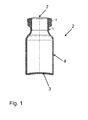
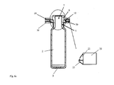
- Fig. 1 An example of such drug containers in the form of vials is in the Fig. 1 shown schematically in a longitudinal section. These have a cylindrical basic shape, with a cylindrical side wall 4 with - within the tolerances - constant inside and outside diameter, which protrudes perpendicularly from a flat bottle bottom 3 and near the upper open end of the vial in a narrowed neck portion 5 of comparatively lower axial length and then into a widened upper edge 6 (also referred to as a rolled edge) merges, which has a larger outer diameter than the associated neck portion 5 and is designed for connection to a closure element. How to get the Fig.
- the underside of the roll edge 6 may be formed chamfered and extend at an acute angle downwards and toward the narrowed neck portion 5.
- the underside of the roll edge 6 may also be flat and extend at a right angle to the narrowed neck portion 5.
- the neck portion 5 may be formed smooth-walled without external thread or may be provided with an external thread for screwing a closure element.
- a plug (not shown) can be inserted whose upper end is connected to the upper edge 6 of the vial gas-tight and protected against the ingress of contaminants into the vial with the upper edge 6 , For example, by crimping or crimping a metal protective film, not shown.
- Such vials are radially symmetrical and formed of a transparent or colored glass or by blow molding or plastic injection molding techniques of a suitable plastic material, and may in principle be internally coated, so that the material of the vial emits as little impurities to the male substance.
- containers in the context of the present application are ampoules, cartridges or syringe or injection containers. Further examples of containers are also double-chamber cartridges and / or double-chamber syringes and / or bottle cartridges (vartridges).
- such containers are used for storing substances or active substances for cosmetic, medical or pharmaceutical applications which are to be stored in one or more components in solid or liquid form in the container.
- storage periods can be many years, which depends in particular on the hydrolytic resistance of the type of glass used.
- containers which are cylindrical, it should be noted that the containers may also have a different profile, for example a square, rectangular or polygonal profile, for the purposes of the present invention.
- such containers have manufacturing tolerances, which may be just one or more tenths of a millimeter, especially in glass containers.
- the containers are fixed according to the invention to a holding structure, as explained below.
- the holder of the container is realized in the transition region of the narrowed neck portion 5 to the widened upper edge 6 or in the region of the narrowed neck portion 5.
- a holding element is arranged in the region of the narrowed neck portion 5, which engages with the narrowed neck portion 5 in a positive engagement or very particularly preferably receives it with a certain radial clearance to compensate for tolerances and different outside diameters of different container types.
- This holding element may be part of or formed by a holding part, which is clipped into a carrier according to embodiments of the invention, as described below, to form a holding structure for simultaneously holding a plurality of containers in openings or receptacles.
- Fig. 2a shows in a perspective plan view of a strip-shaped holding plate 10, at the left and right longitudinal side, in each case at regular intervals to each other a plurality of semicircular recesses 11a, 11b are formed, which are each offset by about half a diameter of the recesses to each other.
- the holding plates 10 are mirror-symmetrical, so they can be reversed clipped in the same way in a carrier. Together, two such retaining plates 10, which contact each other along the contact line 14, form a retaining part, as in FIG Fig. 2b shown in which a plurality of circular openings 13 for holding the vial (Vial) 2 are formed.
- the vials 2 are held positively in the circular retaining seats 13 in the region of their narrowed neck portion below the widened upper edge 6, can in principle also be held by friction, in particular clamped.
- the upper edge 6 of the container 2 can also rest loosely on the holding plates.
- the two holding plates 10 may be directly connected to each other, for example, be releasably locked together to form a subunit in which the vials are held reliably.
- Fig. 2c shows a holding structure according to the present invention with two strip-shaped holding plates 10 according to the Fig. 2a which are clipped into a flat, rectangular support 30, in which in a regular arrangement openings 31 are formed whose opening width is greater than a maximum outer dimension of the vials 2.
- the holding plates 10 are clipped into the top of the carrier 30 in this so the recesses 11a, 11b are aligned with the openings 31 in the support 30 and the vials 2 project downwards through the openings 31 in the support 30 so that the bottoms of the vials 2 are freely accessible from the underside of the support 30.
- the clip 20 has a base 21 from which protrudes a latching or clamping hook 22, which together with the base 21 forms a receptacle 23 in which the edge of the carrier 30 is clamped.
- the retaining clips 20, the carrier 30 and the holding plates 10 are made of suitable plastics, which have sufficient elasticity to the clipping of the holding plates in the carrier 30 and a release of the To enable clip connection.
- the Halteclips be provided in a corresponding manner in the carrier 30 instead of the holding plate 10.
- differently shaped positive-locking elements can also be used.
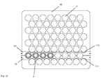
- the Fig. 2f shows a plan view of the support structure (carrier) according to the Fig. 2c ,
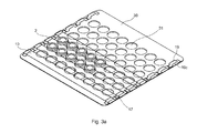
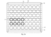
- the Fig. 3a shows in a perspective view of a support structure according to another embodiment of the present invention.
- openings 31 are formed in a regular arrangement, the opening width of which is greater than a maximum outer dimension of the vials 2, so that they are introduced into the openings 31 both from above the carrier 30 and from below the carrier 30 can.
- the width of this gap is preferably slightly larger than the outer dimension of the vial 2 in the neck portion 5 (see. Fig.
- the vials 2 lie loosely on the upper sides of the strip-shaped holding plates 10 with the lower sides of their widened upper edges 6 and are thus secured axially in one direction on the carrier 30, without the vials 2 being kept clamped.
- the vials 2 can also be kept clamped on the carrier 30, preferably in the region of the narrowed neck portion 5 (cf. Fig. 1 ).
- the strip-shaped holding plates 10 may be clipped into the carrier 30 in the manner described above or otherwise releasably secured thereto.
- the strip-shaped holding plates 10 are held clamped on the carrier 30 a and 3b.
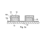
- 30 clamping webs 19 are provided along two opposite longitudinal sides of the carrier, which according to the Fig. 3a each form a plurality of rectangular receptacles 19c, which in the greatly enlarged sectional view according to the Fig. 3c is more apparent.
- the clamping web 19 has a plurality of base portions 19 a for connection to the carrier 30 and a plurality of pairs of vertically projecting from these side walls 19 b, which the rectangular receptacles 19c (see. Fig.
- spacers 18 are arranged with a rectangular cross-section on the top of the carrier 30.
- These are preferably made of an elastic material, for example of an elastic plastic or rubber. According to the Fig. 3c the strip-shaped holding plates 10 are inserted into the gap between the spacers 18 and the clamping bar 19 and are kept clamped therein.
- the upper edges 6 of the vials 2 also rest directly on the upper side of the carrier 30 if the outer diameter of the upper edges 6 of the vials 2 should be greater than the maximum outer dimension in the region of the side walls 4 (cf. Fig. 1 ).
- the strip-shaped retaining plates 10 then rest on the upper edges 6 of the vials 2 to hold the vials 2 axially secured to the carrier 30 in two directions.
- the height of the spacer elements 18 corresponds at least to the height of the widened upper edge 6 of the vials 2 (cf. Fig. 1 ), but may be larger than this. In this way, the axial clearance can be specified, with which the vials 2 are held positively on the carrier 30.
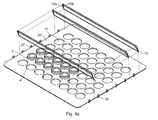
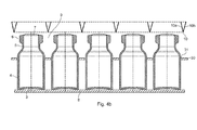
- FIGS. 4a and 4b show in a schematic perspective view and in a sectional view of a holding structure according to another embodiment of the present invention in a state before the containers are held on the support structure.
- the containers 2 are inserted into the openings 31 of the carrier 30.
- the containers may be temporarily supported on an external support surface 8, as schematically shown in FIG Fig. 4b shown.
- the containers 2 are held by a holding device (not shown), for example the holding device of a process station, until the containers 2 are reliably held on the holding structure.
- a holding device not shown
- the upper edges 6 of the containers 2 protrude sufficiently out of the openings 31, so that the undersides of the widened upper edges 6 of the containers 2 for the holding plates 10 are accessible for support.
- the holding plates 10 consist of two holding wings 10a, 10b, which together form a holding plate 10 and a film hinge or the like are interconnected to each other by pivoting about the common connecting line to each other and can be unfolded.
- the holding plates are made of a plastic, in particular by means of a 1K or 2K injection molding process.
- the holding plates 10 can be inserted into the interstices 9 until the upper ends of the holding wings 10a, 10b are slightly below the undersides the widened upper edges 6 of the container 2 are arranged.
- FIGS. 4c and 4d show the thus formed holding structure in a schematic perspective view and in a sectional view in a state in which the containers 2 are held on the holding structure.
- retaining wings 10a, 10b For refolding the retaining wings 10a, 10b, it is advantageous if they are elastically braced against each other by a restoring force, which can be accomplished in a simple manner by the design and the choice of the material of the retaining wings 10a, 10b and their connection area.
- the relaxed rest position of the retaining wings 10a, 10b, the folded position according to the FIGS. 4a and 4b be, in which case the retaining wings 10a, 10b have to be unfolded against an elastic restoring force.
- the weight of the container 2 may be sufficient.
- the containers 2 are actively depressed relative to the holding plates 10 until the bottoms of the widened upper edges 6 of the containers 2 come into contact with the upper ends of the holding wings 10a, 10b and these unfold when further depressing the container 2.
- the retaining wings 10a, 10b are mechanically pressed apart to the position according to the FIGS. 4c and 4d take.
- the relaxed rest position of the retaining wings 10a, 10b and the unfolded position according to the FIGS. 4c and 4d be, in which case the retaining wings 10a, 10b must be folded against an elastic restoring force to the position according to the FIGS. 4a and 4b
- the folding and / or unfolding of the retaining wings 10a, 10b can be supported by mechanical intervention here as well.
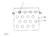
- the support structure consists of a lower support plate 30a with a plurality of openings 31a and an upper support plate 30b with a plurality of openings 31 b, which in the position of the support plates 30a, 30b according to the FIGS. 5a to 5c are arranged in alignment with the openings 31a of the lower support plate 30a.
- the containers 2 can be inserted into the openings 31a, 31b from below or above the lower support plate 30a in this position of the support plates 30a, 30b and be taken down or out again from these openings 31a, 31 b.
- the two support plates 30a, 30b can be displaced parallel to one another in the direction of one of the longitudinal sides, which leads to a reduction in the opening width of the openings formed together by the openings 31a, 31b in the adjustment direction, as in the plan view according to FIG Fig. 5d can be removed.
- the opening width of the openings formed together by the openings 31a, 31b can thus be predetermined in a simple manner.
- the right angles projecting extensions 30 on the bottom of the lower support plate 30a and the edges of the openings 31b in the upper support plate 30b keep the neck portions 5 of the containers clamped together when the opening width of the openings formed together from the openings 31a, 31b corresponds exactly to the outer diameter of the narrowed neck portions 5.
- the opening width of the openings formed together from the openings 31a, 31b is somewhat larger, the widened upper edges 6 of the containers 2 may loosely rest on the edges of the openings 31b in the upper support plate 30b without keeping the containers 2 clamped.
- the position of the two support plate 30a, 30b relative to each other can be secured by means of suitable connecting elements.
- the two support plate 30a, 30b can be locked together in the desired holding position by means of locking elements.
- Fig. 6a shows in a schematic sectional view of the holder of a vial 2 in the support structure according to the Fig. 2c ,
- the vial 2 is held positively in the region of the narrowed neck portion 5.
- the underside of the roll edge 6 of the vial loosely on the top of the holding plates 10, expedient while maintaining a certain radial clearance in the region of the narrowed neck portion fifth
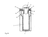
- Fig. 6b shows in a schematic sectional view of the holder of a vial in a variant of the support structure according to the Fig. 2c in which side walls 32 protrude vertically from the underside of the carrier 30, which at least partially surrounds the vial held in the opening of the carrier 30 in the circumferential direction, in order to prevent a collision of immediately adjacent containers.
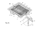
- a support structure as described above may be inserted and transported in a trough-shaped transport and packaging container 60, such as shown in FIG Fig. 6c shown.
- the transport and packaging container 60 is substantially box-shaped or trough-shaped and has a bottom 61, a vertically projecting from this, circumferentially formed side wall 62, a substantially perpendicularly projecting from this step 63 and an upper edge 65 which is formed like a flange is.
- Such a transport and packaging container 60 is preferably made of a Plastic formed, in particular by plastic injection molding technology, and is preferably formed of a clear, transparent plastic to allow a visual visual inspection of the recorded in the transport and packaging container 60 holding structure and held by this container 2.
- the step 63 of the transport container 60 is formed as a circumferential, planar support surface, on which the support structure rests directly.
- the support structure can be precisely positioned in the transport container 60 and the plurality of containers 2 can thus be arranged and held in a regular arrangement and at precisely defined positions in a transport container 10 with standardized dimensions.
- it can be ensured in this way that all bottoms of the containers are arranged in a plane spanned jointly parallel to the bottom 61 or to the upper edge 65 of the transport container 10.
- the lower end of the transport container 60 may also be open in the manner of the upper end, in particular provided with a flange-like lower edge in the manner of the upper edge 65 be, so that the bottoms of the container from the bottom of the transport container 60 forth are freely accessible, for example, for processing steps in a sterile tunnel or in a freeze-drying cabinet.
- the transport container 60 has provisions for identification and / or tracking as follows: As in the enlarged use of Fig. 6c 1, an electronically wireless-readable RFID chip or RuBee chip 52 is disposed in the region of the access recess 63 between the support plate 30 and the side wall 62 and / or the step 63 of the container (a RuBee chip transmits to frequencies that Metal and water can penetrate), which can be read out without contact through the side walls of the packaging unit and on request information regarding the identity, important product properties (manufacturer, content, date of manufacture, expiration date, etc.) etc. issues.
- the chip 52 may be glued into the packaging unit 1 at a suitable location, also elsewhere than shown in the figure.
- the chip 52 may be arranged so that in case of opening the packaging unit 1 or removing the holding plate 30 from the Packing unit out of the chip 52 is destroyed, for example, is torn or disabled. Due to the lack of response of the chip 52 to a radio interrogation, information is thus available which indicates that the packaging unit has been manipulated in some way since the previous packaging. Because the chip 52 does not respond to the radio query. This can serve, for example, to prove the authenticity and integrity of the packaging unit and the containers accommodated therein.
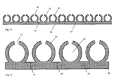
- FIGS. 7a to 7c show in plan views holding parts according to further embodiments according to the present invention.
- a plurality of annular receptacles 43 are arranged distributed at regular intervals spaced from each other.
- the receptacles 43 are formed by two semicircular ring segments 41, between which an insertion opening 42 is formed, through which the containers can be inserted radially inwardly.
- Intermediate spaces 44 are formed between the holding elements formed in this way, so that the holding elements can be formed from comparatively narrow plastic webs which are flexible and elastically bendable.
- the retaining bar 40 is clipped in the manner described above in a carrier (not shown).
- the circular receptacles 43 are formed only along one longitudinal side of the holding web 40.
- predetermined breaking lines or weakening areas 45 are formed in the holding web 40 at regular intervals, where it can be broken apart into smaller subunits.
- FIGS. 7d to 7f exemplify various basic forms of the holding receptacles 43.
- the semicircular webs 41 are relatively strong and thus relatively little elastic.
- the holding receptacle has a square cross-section, wherein the opening width of the receptacle 43 formed by the inner edges 47 is greater than the clear width between the edges 46 of the insertion opening 42.
- a plurality of containers may be held together on a carrier and, while held or at least guided on the carrier, may be treated or further processed.
- this approach is generally suitable for any process steps for treating or processing containers for storing substances for cosmetic, medical, or pharmaceutical applications.
- the holding force exerted on the containers by the holding part is sufficient to reliably hold the containers in the holding part and the holding structure.
- the holding force exerted is greater than the weight of the container, possibly with content and plugs.
- the holding force can also be designed by suitable design of the holding parts so that it is greater than a conventional force in the handling, processing or treatment of the container in a process plant. As a result, a reliable mounting of the container is always guaranteed.
- the containers can be adjusted by simply gripping and adjusting the holding parts together with each held by these containers without much resistance in the openings or recordings, in particular axially advanced or rotated.
- Another significant advantage of the present invention is that the containers can be inserted from above into the openings or receptacles of the carrier and can also be taken out of these again or axially adjusted. The risk of accidental penetration of particles into the internal volume of the container can thus be minimized.
- the support structure (nest) and / or the transport and packaging container (tub) in the context of the present invention may be formed of a thermoplastic, thermosetting or elastomeric plastic, and / or provided at least portions of the support structure or the carrier with a reibredumpden coating be to facilitate the insertion and removal of the containers.
- so-called cycloolefin copolymers (COC) or cycloolefin polymers (COP) can be used.
Landscapes
- Health & Medical Sciences (AREA)
- Engineering & Computer Science (AREA)
- Mechanical Engineering (AREA)
- Clinical Laboratory Science (AREA)
- Chemical & Material Sciences (AREA)
- Chemical Kinetics & Catalysis (AREA)
- Pharmacology & Pharmacy (AREA)
- Life Sciences & Earth Sciences (AREA)
- Animal Behavior & Ethology (AREA)
- General Health & Medical Sciences (AREA)
- Public Health (AREA)
- Veterinary Medicine (AREA)
- Packages (AREA)
- Medical Preparation Storing Or Oral Administration Devices (AREA)
- Details Of Rigid Or Semi-Rigid Containers (AREA)
Claims (12)
- Une structure de support pour le support concomitant d'une pluralité de récipients (2) destinées aux applications médicales, pharmaceutiques ou cosmétiques, comprenant un élément porteur plat (30), de forme rectangulaire (30) ayant une pluralité d'ouvertures ou de réceptacles (31), caractérisé par une pluralité d'éléments de support (10), qui sont couplés de manière libérable à l'élément porteur (30), qui prennent chacun la forme d'une bande et qui s'étendent dans la direction longitudinale de l'élément porteur (30), dans laquelle les éléments support sont configurés pour supporter une pluralité de récipients (2) pour ledit élément porteur au moyen d'une complémentarité positive, laquelle est formée par le couplage de l'élément support respective (10) avec l'élément porteur (30) de telle façon à ce que les récipients soutenus sur l'élément porteur s'étend dans les ouvertures ou réceptacles (31 b) de l'élément support.
- La structure de support de la revendication 1, dans laquelle le couplage de complémentarité positive est configuré de façon à ce que les récipients (2) sont retenus aux éléments de support (10) suivant une direction axiale dans la région d'une partie de nez resserrée (5) et en dessous du bord supérieur étendu (6) suivant la partie de nez resserrée.
- La structure de support de la revendication 1 ou 2, dans laquelle le couplage de complémentarité positive est formée de telle manière que les récipients (2) reposent respectivement de manière libre avec le côté inférieur du bord supérieur étendue (6) sur les éléments de support (10).
- La structure de support de l'une quelconque des revendications précédentes, dans laquelle des éléments de support annulaires respectifs (41) sont formées sur les formes des éléments de support (10) pour entourer la périphérie extérieure des récipients (2) suivant une collaboration appropriée positive, dans laquelle les éléments de support annulaires respectifs (41) sont disposés à des distances uniformes les unes par rapport aux autres et le long de l'élément de support respectif et dans laquelle la largeur d'ouverture des réceptacles annulaires est plus grande que le diamètre extérieure de la partie de nez resserrée (5) des récipients (2) mais inférieure au diamètre extérieur du bord supérieur des récipients (5), suivant la partie de nez resserrée (5).
- La structure de support selon l'une quelconque des revendications 1 à 3, dans laquelle des paires respectives d'éléments de support adjacents (10) supportent la pluralité de récipients (2) sur l'élément porteur (30) en rangées et en colonnes, dans laquelle une pluralité d'évidements semi-circulaires (11a, 11 b) est respectivement formée le long d'au moins un côté longitudinal des éléments supports, qui forment une pluralité de réceptacles annulaire (13) en coopération avec les évidements semi-circulaires d'un élément support directement adjacent en forme de bande.
- La structure de support selon la revendication 5, dans laquelle les évidements semi-circulaires (11a, 11b) sont décalés les uns par rapport aux autres le long des côtés longitudinaux opposés des éléments support (10).
- La structure de support selon l'une quelconque des revendications 1 à 3, dans laquelle des paires respectives d'éléments de support adjacents (10) supportent la pluralité de récipients (2) sur l'élément porteur (30) en rangées et en colonnes, dans laquelle les éléments de support comportent chacun deux ailes (10a, 10b) qui sont contraintes élastiquement les uns relativement aux autres de telle façon que, dans une première position des éléments de support dans laquelle les ailes (10a, 10b) sont déplacées l'une vers l'autre, les éléments supports (10) peuvent être insérés dans des interstices (9) entre les extrémités supérieures des ranges et colonnes des récipients (2), et, dans une seconde position des éléments supports, dans laquelle les ailes (10a, 10b) sont pliées au loin, les éléments support (10) supportent les récipients sur l'élément porteur en rangées et en colonnes.
- La structure de support selon l'une quelconque des revendications précédentes, dans laquelle les éléments de support (10, 30a) sont configurés de telle manière que les fonds des récipients devant être soutenus sont librement accessibles depuis un côté inférieur de la structure de support pour un traitement ou conditionnement des récipients, pendant qu'ils sont soutenus sur l'élément support.
- La structure de support selon l'une quelconque des revendications précédentes, dans laquelle les éléments supports (10) sont respectivement tenus sur l'élément porteur (30) par serrage.
- La structure de support selon l'une quelconque des revendications 1 à 8, dans laquelle les éléments supports (10) sont respectivement couplés à l'élément porteur (30) au moyen d'un couplage par agrafe, dans laquelle au moins un premier élément de verrouillage est disposé sur l'élément porteur ou sur l'élément support respectif, et dans laquelle au moins un second élément de verrouillage est disposé sur l'élément de support respectif ou sur l'élément porteur, et dans laquelle les premier et second éléments de verrouillage peuvent être verrouillés pour coupler l'élément porteur (30) avec l'élément de support respectif (10, 30a).
- La structure de support selon la revendication 10, dans laquelle une pluralité d'ouvertures (31 a) est formée dans les éléments supports (30a) et les éléments supports sont soutenus sur l'élément porteur de telle manière qu'ils peuvent être déplacés parallèlement vis à vis de l'élément porteur (30b), dans laquelle, dans une première position de l'élément support relativement à l'élément porteur, les ouvertures (31a) des éléments supports sont alignées avec les ouvertures (31) ou les réceptacles de l'élément porteur (30b) de telle manière que les extrémités supérieures des récipients peuvent être respectivement insérées dans les ouvertures de l'élément support, et dans laquelle les éléments supports peuvent être déplacé par un déplacement parallèle relativement à l'élément porteur vers une seconde position, dans laquelle la complémentarité positive est réalisée par la coopération des ouvertures (31a) dans l'élément support (30a) avec les ouvertures (31b) ou les réceptacles dans l'élément porteur (30b) pour soutenir les récipients sur l'élément porteur.
- Un récipient de transport ou de conditionnement pour une pluralité de récipients (2) pour des substances médicales, pharmaceutiques ou des applications cosmétiques, comprenant un récipient en forme de boîte (60) caractérisé par au moins une structure de support selon l'une quelconque des revendications précédentes, qui est logée dans le récipient en forme de boîte (60) pour supporter conjointement la pluralité de récipients.
Applications Claiming Priority (1)
| Application Number | Priority Date | Filing Date | Title |
|---|---|---|---|
| DE102013111600.0A DE102013111600B4 (de) | 2013-10-21 | 2013-10-21 | Haltestruktur zum Halten von Behältern für Substanzen für medizinische, pharmazeutische oder kosmetische Anwendungen, sowie Transport- und Verpackungsbehälter mit selbiger |
Publications (3)
| Publication Number | Publication Date |
|---|---|
| EP2862809A2 EP2862809A2 (fr) | 2015-04-22 |
| EP2862809A3 EP2862809A3 (fr) | 2015-12-23 |
| EP2862809B1 true EP2862809B1 (fr) | 2016-10-05 |
Family
ID=51703095
Family Applications (1)
| Application Number | Title | Priority Date | Filing Date |
|---|---|---|---|
| EP14189210.9A Active EP2862809B1 (fr) | 2013-10-21 | 2014-10-16 | Structure de support de récipients pour substances destinées aux applications médicales, pharmaceutiques ou cosmétiques ainsi que récipient de transport ou d'emballage en étant équipé |
Country Status (6)
| Country | Link |
|---|---|
| US (1) | US10064787B2 (fr) |
| EP (1) | EP2862809B1 (fr) |
| KR (1) | KR101695065B1 (fr) |
| CN (1) | CN104555014B (fr) |
| DE (1) | DE102013111600B4 (fr) |
| MX (1) | MX351586B (fr) |
Families Citing this family (40)
| Publication number | Priority date | Publication date | Assignee | Title |
|---|---|---|---|---|
| ITUD20120127A1 (it) * | 2012-07-12 | 2014-01-13 | Cps Color Equipment S P A Con Unic O Socio | Dispositivo di supporto per serbatoi di prodotti coloranti fluidi |
| EP3345587B1 (fr) * | 2015-09-04 | 2022-04-13 | Daikyo Seiko, LTD. | Élément porte-récipients et ensemble de récipients médicaux |
| JP6929291B2 (ja) | 2016-01-27 | 2021-09-01 | ウエスト ファーマスーティカル サービシーズ インコーポレイテッド | 六角チムニーを備えた中心オフセット付きのシリンジネスト |
| DE102016121086A1 (de) * | 2016-11-04 | 2018-05-09 | Schott Schweiz Ag | Haltestruktur zum Halten einer Mehrzahl von Behältern für pharmazeutische, medizinische oder kosmetische Zwecke sowie Transport- oder Verpackungsbehälter mit selbiger |
| DE102017004233A1 (de) | 2017-05-02 | 2018-11-08 | Seidenader Maschinenbau Gmbh | Zentriervorrichtung |
| JP7165651B2 (ja) * | 2017-05-12 | 2022-11-04 | ユニバーサル・バイオ・リサーチ株式会社 | 核酸検出用カートリッジ |
| WO2018206841A1 (fr) * | 2017-05-12 | 2018-11-15 | Thermo Fisher Scientific Oy | Support de récipient et ratelier de récipients |
| EP3691714B1 (fr) * | 2017-10-02 | 2023-11-29 | Becton Dickinson France | Dispositif d'emballage conçu pour supporter des récipients médicaux et procédé pour retirer les récipients médicaux depuis ledit dispositif d'emballage |
| CN107737618A (zh) * | 2017-10-27 | 2018-02-27 | 天津长寿源健康科技有限公司 | 一种试管放置架 |
| US11577953B2 (en) * | 2017-11-14 | 2023-02-14 | Sartorius Stedim North America, Inc. | System for simultaneous distribution of fluid to multiple vessels and method of using the same |
| US12252391B2 (en) | 2017-11-14 | 2025-03-18 | Sartorius Stedim North America Inc. | System for simultaneous distribution of fluid to multiple vessels and method of using the same |
| US11691866B2 (en) | 2017-11-14 | 2023-07-04 | Sartorius Stedim North America Inc. | System for simultaneous distribution of fluid to multiple vessels and method of using the same |
| US11319201B2 (en) * | 2019-07-23 | 2022-05-03 | Sartorius Stedim North America Inc. | System for simultaneous filling of multiple containers |
| RU2762811C1 (ru) * | 2017-12-14 | 2021-12-23 | Филип Моррис Продактс С.А. | Защищенная от детей емкость |
| EP3563892B1 (fr) * | 2018-05-02 | 2024-03-13 | Becton Dickinson France | Dispositif de maintien destiné à supporter une pluralité de récipients médicaux, ensemble de récipients médicaux comprenant ce dispositif de maintien et procédé de fabrication d'un récipient médical |
| WO2019216827A1 (fr) * | 2018-05-08 | 2019-11-14 | Lam Choon Sen David | Séparateur et plaque de séparation |
| IT201800009300A1 (it) * | 2018-10-10 | 2020-04-10 | Ima Industria Macch Automatiche Spa | Dispositivo di pesatura di contenitori. |
| CN109292222A (zh) * | 2018-11-27 | 2019-02-01 | 重庆旺达汽车零部件有限公司 | 一种螺栓螺母放置盒 |
| WO2020183195A1 (fr) * | 2019-03-14 | 2020-09-17 | ABgene Limited | Plaques multipuits divisibles |
| CN114008652A (zh) * | 2019-07-01 | 2022-02-01 | 贝克顿迪金森法国公司 | 用于跟踪与医疗容器的处理相关的数据的系统和方法 |
| EP3771656A1 (fr) * | 2019-07-30 | 2021-02-03 | SCHOTT Schweiz AG | Conditionnement de transport pour récipients et procédé de déballage de récipients |
| EP3798142B1 (fr) * | 2019-09-25 | 2024-05-01 | SCHOTT Pharma AG & Co. KGaA | Dispositif de support des récipients |
| CN114760884A (zh) * | 2019-12-16 | 2022-07-15 | 美国西门子医学诊断股份有限公司 | 管框架装置、管框架组件以及固持管的方法 |
| EP3848304B1 (fr) * | 2020-01-10 | 2024-03-13 | SCHOTT Pharma Schweiz AG | Dispositif de transport pour récipients médicaux |
| EP3851089A1 (fr) * | 2020-01-20 | 2021-07-21 | SCHOTT Schweiz AG | Dispositif de support pour supporter une pluralité de récipients dans un engagement positif établi par un mouvement de déplacement |
| US11732964B2 (en) * | 2020-04-15 | 2023-08-22 | Navinta Iii Inc | Lyophilization promoting element |
| FR3114087B1 (fr) | 2020-09-11 | 2023-07-14 | A Raymond Et Cie | Systeme et procede d’emballage de bouchons medicaux compose d’une coiffe et d’un obturateur |
| FR3114081B1 (fr) | 2020-09-11 | 2022-08-19 | A Raymond Et Cie | Plateau de livraison et systeme d’emballage d’elements medicaux |
| EP3974337B1 (fr) * | 2020-09-25 | 2024-11-06 | SCHOTT Pharma Schweiz AG | Dispositif de retenue limitant le mouvement de conteneurs d'emballage primaire au niveau d'une première position longitudinale et d'autres positions longitudinales |
| MX2022005963A (es) | 2021-05-18 | 2023-03-01 | Gerresheimer Glas Gmbh | Contenedor para unidades de envasado. |
| MX2022005952A (es) | 2021-05-18 | 2023-04-10 | Gerresheimer Glas Gmbh | Transporte de unidades de envase. |
| US12319466B2 (en) | 2021-05-18 | 2025-06-03 | Gerresheimer Glas Gmbh | Transporting packaging units |
| WO2022251230A1 (fr) * | 2021-05-24 | 2022-12-01 | Sio2 Medical Products, Inc. | Authentification/suivi d'emballages pharmaceutiques à l'aide de cristaux marqueurs de décalage d'onde |
| US12239127B2 (en) | 2021-07-28 | 2025-03-04 | Sartorius Stedim North America Inc. | Thermal capacitors, systems, and methods for rapid freezing or heating of biological materials |
| FR3125961B1 (fr) | 2021-08-05 | 2024-01-12 | A Raymond Et Cie | Conditionnement pour dispositifs medicaux |
| BE1030359B1 (fr) | 2022-03-17 | 2023-10-16 | Aseptic Tech Sa | Système de manipulation de containers contenant une substance médicinale et un procédé de manipulation |
| CN114620355B (zh) * | 2022-05-12 | 2022-08-19 | 达州达运公路物流港有限公司 | 一种多形态快速调整式贮存装置及使用方法 |
| TWI817499B (zh) * | 2022-05-12 | 2023-10-01 | 鴻寶興業有限公司 | 集裝袋束口夾送料機 |
| CN115108141A (zh) * | 2022-07-08 | 2022-09-27 | 安徽老炊食品有限公司 | 一种储存微生物菌群的贮存装置 |
| CN116253050A (zh) * | 2022-12-27 | 2023-06-13 | 安徽德亚电池有限公司 | 一种电芯转运装置 |
Family Cites Families (22)
| Publication number | Priority date | Publication date | Assignee | Title |
|---|---|---|---|---|
| US3643812A (en) | 1970-06-12 | 1972-02-22 | Owens Illinois Inc | Tube storage rack |
| US4278176A (en) * | 1979-07-02 | 1981-07-14 | University Of Utah | Gradient tube rack and method |
| DE3836163A1 (de) * | 1988-10-24 | 1990-04-26 | Berthold Lab Prof R | Aufnahmesystem fuer mehrere probengefaesse zur durchfuehrung von strahlungsmessungen |
| US5700429A (en) * | 1995-04-19 | 1997-12-23 | Roche Diagnostic Systems, Inc. | Vessel holder for automated analyzer |
| DE19825909C1 (de) | 1998-06-10 | 1999-11-25 | Graffinity Pharm Design Gmbh | Reaktorträger mit mehreren Mikroprobenaufnahmekammern |
| JP2000272683A (ja) | 1999-03-19 | 2000-10-03 | Hokuetsu Paper Mills Ltd | ボトルキャリア |
| DE60336627D1 (de) | 2003-02-24 | 2011-05-19 | Becton Dickinson France | Vorrichtung zur Gruppierung von Spritzen |
| US8100263B2 (en) | 2004-07-01 | 2012-01-24 | West Pharmaceutical Services, Inc. | Vacuum package system |
| AU2005283083A1 (en) | 2004-07-01 | 2006-03-16 | Daikyo Seiko, Ltd. | Vacuum package system and method |
| DE102005060328A1 (de) | 2005-12-16 | 2007-07-05 | Poly-Clip System Gmbh & Co. Kg | Verfahren und Vorrichtung zum Umverteilen von pastösem Füllgut |
| CN101652152B (zh) | 2007-03-05 | 2013-03-20 | 株式会社大协精工 | 医用容器 |
| CH702317B1 (it) * | 2007-08-02 | 2011-06-15 | Stevanato Group Internat As | Struttura di confezione di flaconi in vetro ad uso farmaceutico. |
| IT1393082B1 (it) | 2009-01-27 | 2012-04-11 | Semafra S A | Struttura di imballo di contenitori ad uso farmaceutico |
| DE102009027454A1 (de) | 2009-07-03 | 2011-01-05 | Robert Bosch Gmbh | Aufnahmebehälter für pharmazeutische Behältnisse |
| IT1399750B1 (it) | 2010-04-30 | 2013-05-03 | Stevanato Group Internat As | Struttura di imballaggio per contenitori ad uso farmaceutico |
| AU2011255563B2 (en) | 2010-05-18 | 2013-11-21 | St Reproductive Technologies, Llc | Method and apparatus for suspending a container |
| US9630745B2 (en) | 2010-09-17 | 2017-04-25 | Flexiways Sprl | Packaging for the storage, protection and transport of syringes |
| HUE030473T2 (en) | 2010-09-28 | 2017-05-29 | Becton Dickinson France | Packaging for cylindrical containers |
| US20130108522A1 (en) * | 2011-10-27 | 2013-05-02 | Molecular Bioproducts, Inc. | Self Locking Snap Plate |
| DE102012103899B4 (de) | 2012-05-03 | 2016-09-22 | Schott Ag | Verfahren und Vorrichtung zur Behandlung von Behältern zur Aufbewahrung von Substanzen für medizinische oder pharmazeutische Anwendungen |
| ITVI20120215A1 (it) | 2012-08-30 | 2014-03-01 | Fedegari Autoclavi | Struttura per il confezionamento di componenti per contenitori ad uso farmaceutico |
| DE102012110973B4 (de) | 2012-11-14 | 2023-10-19 | Schott Pharma Ag & Co. Kgaa | Verwendung eines Halteelements zum Halten eines Behälters, sowie Haltestruktur |
-
2013
- 2013-10-21 DE DE102013111600.0A patent/DE102013111600B4/de active Active
-
2014
- 2014-10-16 EP EP14189210.9A patent/EP2862809B1/fr active Active
- 2014-10-20 MX MX2014012707A patent/MX351586B/es active IP Right Grant
- 2014-10-21 US US14/519,725 patent/US10064787B2/en active Active
- 2014-10-21 CN CN201410563902.6A patent/CN104555014B/zh active Active
- 2014-10-21 KR KR1020140142558A patent/KR101695065B1/ko active Active
Also Published As
| Publication number | Publication date |
|---|---|
| KR101695065B1 (ko) | 2017-01-23 |
| CN104555014A (zh) | 2015-04-29 |
| DE102013111600B4 (de) | 2018-04-05 |
| MX2014012707A (es) | 2015-06-24 |
| CN104555014B (zh) | 2017-06-30 |
| DE102013111600A1 (de) | 2015-04-23 |
| MX351586B (es) | 2017-10-20 |
| KR20150045905A (ko) | 2015-04-29 |
| US10064787B2 (en) | 2018-09-04 |
| US20150108034A1 (en) | 2015-04-23 |
| EP2862809A3 (fr) | 2015-12-23 |
| EP2862809A2 (fr) | 2015-04-22 |
Similar Documents
| Publication | Publication Date | Title |
|---|---|---|
| EP2862809B1 (fr) | Structure de support de récipients pour substances destinées aux applications médicales, pharmaceutiques ou cosmétiques ainsi que récipient de transport ou d'emballage en étant équipé | |
| EP2659979B1 (fr) | Structure de support portant simultanément une pluralité de récipients pour des applications médicales, pharmaceutiques ou cosmétiques ainsi que récipient de transport ou d'emballage | |
| EP2872843B1 (fr) | Structure de retenue permettant de retenir simultanément une pluralité de récipients pour des substances destinées à des applications médicales, pharmaceutiques ou cosmétiques, et récipients de transport ou d'emballage contenant lesdites substances | |
| EP2659980B1 (fr) | Structure de support pour le support simultané d'une pluralité de récipients médicaux ou pharmaceutiques ainsi que récipient de transport ou d'emballage doté d'une telle structure | |
| EP2659922B1 (fr) | Structure de support pour le support simultané d'une pluralité de récipients médicaux ou pharmaceutiques ainsi que récipient de transport ou d'emballage doté d'une telle structure | |
| EP2916885B1 (fr) | Dispositif et procédé destinés au traitement ou manipulation des récipients pour les substances pour les applications médicales, pharmaceutiques ou cosmétiques | |
| EP2848882B1 (fr) | Procédé et dispositif de sertissage de récipients pour la conservation de substances destinées à des applications médicales, pharmaceutiques ou cosmétiques | |
| EP2868593B1 (fr) | Structure de support pour le support simultané d'une pluralité de récipients pour des substances pour des applications médicales, pharmaceutiques ou cosmétiques, récipient de transport ou d'emballage doté de celle-ci et procédé | |
| EP2905235B1 (fr) | Récipient d'emballage et de transport destiné à recevoir une pluralité de récipients pour des applications médicales, pharmaceutiques ou cosmétiques et son procédé et ses utilisations | |
| EP3535057B1 (fr) | Structure de retenue servant à retenir une pluralité de contenants pour usage pharmaceutique, médical ou cosmétique ainsi que contenant de transport ou d'emballage la comprenant | |
| EP3199187B1 (fr) | Plaque de support pour récipients pharmaceutiques | |
| DE102012103899B4 (de) | Verfahren und Vorrichtung zur Behandlung von Behältern zur Aufbewahrung von Substanzen für medizinische oder pharmazeutische Anwendungen | |
| DE102012110339B4 (de) | Haltestruktur zum gleichzeitigen Halten einer Mehrzahl von medizinischen oder pharmazeutischen Behältern sowie Transport- oder Verpackungsbehälter mit Selbiger und Verfahren zur Behandlung solcher Behälter | |
| DE202018106510U1 (de) | Haltestruktur mit einer Mehrzahl von daran gehaltenen Behältern für Substanzen für pharmazeutische, medizinische oder kosmetische Anwendungen sowie Transport- oder Verpackungsbehälter mit selbiger | |
| DE102017101398A1 (de) | Haltestruktur zum gleichzeitigen Halten einer Mehrzahl von Behältern für Substanzen für pharmazeutische, medizinische oder kosmetische Anwendungen, Transportgebilde und Transport- oder Verpackungsbehälter mit selbiger | |
| DE102016123147A1 (de) | Haltestruktur zum gleichzeitigen Halten einer Mehrzahl von Vials, Verwendung hiervon sowie Verfahren zur Behandlung solcher Vials | |
| EP3534986A1 (fr) | Structure de retenue servant à retenir simultanément une pluralité de contenants pour substances à usage pharmaceutique, médical ou cosmétique, structure de transport et contenant de transport ou d'emballage la comportant | |
| DE102012108215A1 (de) | Haltestruktur zum gleichzeitigen Halten einer Mehrzahl von Behältern für Substanzen für medizinische, pharmazeutische oder kosmetische Anwendungen sowie Transport- oder Verpackungsbehälter mit selbiger | |
| DE102012110973B4 (de) | Verwendung eines Halteelements zum Halten eines Behälters, sowie Haltestruktur | |
| EP2659981B1 (fr) | Récipient de transport ou d'emballage avec structure de support pour le support simultané d'une pluralité de récipients pour des applications médicales, pharmaceutiques ou cosmétiques et procédé de traitement de tels récipients |
Legal Events
| Date | Code | Title | Description |
|---|---|---|---|
| PUAI | Public reference made under article 153(3) epc to a published international application that has entered the european phase |
Free format text: ORIGINAL CODE: 0009012 |
|
| 17P | Request for examination filed |
Effective date: 20141016 |
|
| AK | Designated contracting states |
Kind code of ref document: A2 Designated state(s): AL AT BE BG CH CY CZ DE DK EE ES FI FR GB GR HR HU IE IS IT LI LT LU LV MC MK MT NL NO PL PT RO RS SE SI SK SM TR |
|
| AX | Request for extension of the european patent |
Extension state: BA ME |
|
| RIC1 | Information provided on ipc code assigned before grant |
Ipc: B01L 9/00 20060101ALI20150608BHEP Ipc: B65D 25/10 20060101AFI20150608BHEP |
|
| PUAL | Search report despatched |
Free format text: ORIGINAL CODE: 0009013 |
|
| AK | Designated contracting states |
Kind code of ref document: A3 Designated state(s): AL AT BE BG CH CY CZ DE DK EE ES FI FR GB GR HR HU IE IS IT LI LT LU LV MC MK MT NL NO PL PT RO RS SE SI SK SM TR |
|
| AX | Request for extension of the european patent |
Extension state: BA ME |
|
| RIC1 | Information provided on ipc code assigned before grant |
Ipc: B01L 9/06 20060101ALI20151113BHEP Ipc: B65D 25/10 20060101AFI20151113BHEP Ipc: B01L 3/00 20060101ALN20151113BHEP |
|
| R17P | Request for examination filed (corrected) |
Effective date: 20160413 |
|
| RBV | Designated contracting states (corrected) |
Designated state(s): AL AT BE BG CH CY CZ DE DK EE ES FI FR GB GR HR HU IE IS IT LI LT LU LV MC MK MT NL NO PL PT RO RS SE SI SK SM TR |
|
| GRAP | Despatch of communication of intention to grant a patent |
Free format text: ORIGINAL CODE: EPIDOSNIGR1 |
|
| RIC1 | Information provided on ipc code assigned before grant |
Ipc: B01L 9/06 20060101ALI20160520BHEP Ipc: B01L 3/00 20060101ALN20160520BHEP Ipc: B65D 25/10 20060101AFI20160520BHEP |
|
| RIC1 | Information provided on ipc code assigned before grant |
Ipc: B01L 9/06 20060101ALI20160531BHEP Ipc: B01L 3/00 20060101ALN20160531BHEP Ipc: B65D 25/10 20060101AFI20160531BHEP |
|
| INTG | Intention to grant announced |
Effective date: 20160615 |
|
| GRAS | Grant fee paid |
Free format text: ORIGINAL CODE: EPIDOSNIGR3 |
|
| GRAA | (expected) grant |
Free format text: ORIGINAL CODE: 0009210 |
|
| AK | Designated contracting states |
Kind code of ref document: B1 Designated state(s): AL AT BE BG CH CY CZ DE DK EE ES FI FR GB GR HR HU IE IS IT LI LT LU LV MC MK MT NL NO PL PT RO RS SE SI SK SM TR |
|
| REG | Reference to a national code |
Ref country code: GB Ref legal event code: FG4D Free format text: NOT ENGLISH |
|
| REG | Reference to a national code |
Ref country code: CH Ref legal event code: EP |
|
| REG | Reference to a national code |
Ref country code: AT Ref legal event code: REF Ref document number: 834409 Country of ref document: AT Kind code of ref document: T Effective date: 20161015 |
|
| REG | Reference to a national code |
Ref country code: FR Ref legal event code: PLFP Year of fee payment: 3 |
|
| REG | Reference to a national code |
Ref country code: IE Ref legal event code: FG4D Free format text: LANGUAGE OF EP DOCUMENT: GERMAN |
|
| REG | Reference to a national code |
Ref country code: DE Ref legal event code: R096 Ref document number: 502014001639 Country of ref document: DE |
|
| REG | Reference to a national code |
Ref country code: NL Ref legal event code: MP Effective date: 20161005 |
|
| REG | Reference to a national code |
Ref country code: LT Ref legal event code: MG4D |
|
| PG25 | Lapsed in a contracting state [announced via postgrant information from national office to epo] |
Ref country code: LV Free format text: LAPSE BECAUSE OF FAILURE TO SUBMIT A TRANSLATION OF THE DESCRIPTION OR TO PAY THE FEE WITHIN THE PRESCRIBED TIME-LIMIT Effective date: 20161005 |
|
| PG25 | Lapsed in a contracting state [announced via postgrant information from national office to epo] |
Ref country code: GR Free format text: LAPSE BECAUSE OF FAILURE TO SUBMIT A TRANSLATION OF THE DESCRIPTION OR TO PAY THE FEE WITHIN THE PRESCRIBED TIME-LIMIT Effective date: 20170106 Ref country code: NO Free format text: LAPSE BECAUSE OF FAILURE TO SUBMIT A TRANSLATION OF THE DESCRIPTION OR TO PAY THE FEE WITHIN THE PRESCRIBED TIME-LIMIT Effective date: 20170105 Ref country code: SE Free format text: LAPSE BECAUSE OF FAILURE TO SUBMIT A TRANSLATION OF THE DESCRIPTION OR TO PAY THE FEE WITHIN THE PRESCRIBED TIME-LIMIT Effective date: 20161005 Ref country code: LT Free format text: LAPSE BECAUSE OF FAILURE TO SUBMIT A TRANSLATION OF THE DESCRIPTION OR TO PAY THE FEE WITHIN THE PRESCRIBED TIME-LIMIT Effective date: 20161005 |
|
| PG25 | Lapsed in a contracting state [announced via postgrant information from national office to epo] |
Ref country code: ES Free format text: LAPSE BECAUSE OF FAILURE TO SUBMIT A TRANSLATION OF THE DESCRIPTION OR TO PAY THE FEE WITHIN THE PRESCRIBED TIME-LIMIT Effective date: 20161005 Ref country code: PT Free format text: LAPSE BECAUSE OF FAILURE TO SUBMIT A TRANSLATION OF THE DESCRIPTION OR TO PAY THE FEE WITHIN THE PRESCRIBED TIME-LIMIT Effective date: 20170206 Ref country code: FI Free format text: LAPSE BECAUSE OF FAILURE TO SUBMIT A TRANSLATION OF THE DESCRIPTION OR TO PAY THE FEE WITHIN THE PRESCRIBED TIME-LIMIT Effective date: 20161005 Ref country code: RS Free format text: LAPSE BECAUSE OF FAILURE TO SUBMIT A TRANSLATION OF THE DESCRIPTION OR TO PAY THE FEE WITHIN THE PRESCRIBED TIME-LIMIT Effective date: 20161005 Ref country code: NL Free format text: LAPSE BECAUSE OF FAILURE TO SUBMIT A TRANSLATION OF THE DESCRIPTION OR TO PAY THE FEE WITHIN THE PRESCRIBED TIME-LIMIT Effective date: 20161005 Ref country code: PL Free format text: LAPSE BECAUSE OF FAILURE TO SUBMIT A TRANSLATION OF THE DESCRIPTION OR TO PAY THE FEE WITHIN THE PRESCRIBED TIME-LIMIT Effective date: 20161005 Ref country code: IS Free format text: LAPSE BECAUSE OF FAILURE TO SUBMIT A TRANSLATION OF THE DESCRIPTION OR TO PAY THE FEE WITHIN THE PRESCRIBED TIME-LIMIT Effective date: 20170205 Ref country code: HR Free format text: LAPSE BECAUSE OF FAILURE TO SUBMIT A TRANSLATION OF THE DESCRIPTION OR TO PAY THE FEE WITHIN THE PRESCRIBED TIME-LIMIT Effective date: 20161005 |
|
| REG | Reference to a national code |
Ref country code: DE Ref legal event code: R097 Ref document number: 502014001639 Country of ref document: DE |
|
| REG | Reference to a national code |
Ref country code: IE Ref legal event code: MM4A |
|
| PG25 | Lapsed in a contracting state [announced via postgrant information from national office to epo] |
Ref country code: SK Free format text: LAPSE BECAUSE OF FAILURE TO SUBMIT A TRANSLATION OF THE DESCRIPTION OR TO PAY THE FEE WITHIN THE PRESCRIBED TIME-LIMIT Effective date: 20161005 Ref country code: MC Free format text: LAPSE BECAUSE OF FAILURE TO SUBMIT A TRANSLATION OF THE DESCRIPTION OR TO PAY THE FEE WITHIN THE PRESCRIBED TIME-LIMIT Effective date: 20161005 Ref country code: RO Free format text: LAPSE BECAUSE OF FAILURE TO SUBMIT A TRANSLATION OF THE DESCRIPTION OR TO PAY THE FEE WITHIN THE PRESCRIBED TIME-LIMIT Effective date: 20161005 Ref country code: EE Free format text: LAPSE BECAUSE OF FAILURE TO SUBMIT A TRANSLATION OF THE DESCRIPTION OR TO PAY THE FEE WITHIN THE PRESCRIBED TIME-LIMIT Effective date: 20161005 Ref country code: CZ Free format text: LAPSE BECAUSE OF FAILURE TO SUBMIT A TRANSLATION OF THE DESCRIPTION OR TO PAY THE FEE WITHIN THE PRESCRIBED TIME-LIMIT Effective date: 20161005 Ref country code: DK Free format text: LAPSE BECAUSE OF FAILURE TO SUBMIT A TRANSLATION OF THE DESCRIPTION OR TO PAY THE FEE WITHIN THE PRESCRIBED TIME-LIMIT Effective date: 20161005 |
|
| PLBE | No opposition filed within time limit |
Free format text: ORIGINAL CODE: 0009261 |
|
| STAA | Information on the status of an ep patent application or granted ep patent |
Free format text: STATUS: NO OPPOSITION FILED WITHIN TIME LIMIT |
|
| PG25 | Lapsed in a contracting state [announced via postgrant information from national office to epo] |
Ref country code: SM Free format text: LAPSE BECAUSE OF FAILURE TO SUBMIT A TRANSLATION OF THE DESCRIPTION OR TO PAY THE FEE WITHIN THE PRESCRIBED TIME-LIMIT Effective date: 20161005 Ref country code: LU Free format text: LAPSE BECAUSE OF NON-PAYMENT OF DUE FEES Effective date: 20161016 Ref country code: BG Free format text: LAPSE BECAUSE OF FAILURE TO SUBMIT A TRANSLATION OF THE DESCRIPTION OR TO PAY THE FEE WITHIN THE PRESCRIBED TIME-LIMIT Effective date: 20170105 |
|
| 26N | No opposition filed |
Effective date: 20170706 |
|
| REG | Reference to a national code |
Ref country code: FR Ref legal event code: PLFP Year of fee payment: 4 |
|
| PG25 | Lapsed in a contracting state [announced via postgrant information from national office to epo] |
Ref country code: IE Free format text: LAPSE BECAUSE OF NON-PAYMENT OF DUE FEES Effective date: 20161016 Ref country code: SI Free format text: LAPSE BECAUSE OF FAILURE TO SUBMIT A TRANSLATION OF THE DESCRIPTION OR TO PAY THE FEE WITHIN THE PRESCRIBED TIME-LIMIT Effective date: 20161005 |
|
| PG25 | Lapsed in a contracting state [announced via postgrant information from national office to epo] |
Ref country code: HU Free format text: LAPSE BECAUSE OF FAILURE TO SUBMIT A TRANSLATION OF THE DESCRIPTION OR TO PAY THE FEE WITHIN THE PRESCRIBED TIME-LIMIT; INVALID AB INITIO Effective date: 20141016 |
|
| PG25 | Lapsed in a contracting state [announced via postgrant information from national office to epo] |
Ref country code: MT Free format text: LAPSE BECAUSE OF FAILURE TO SUBMIT A TRANSLATION OF THE DESCRIPTION OR TO PAY THE FEE WITHIN THE PRESCRIBED TIME-LIMIT Effective date: 20161005 Ref country code: MK Free format text: LAPSE BECAUSE OF FAILURE TO SUBMIT A TRANSLATION OF THE DESCRIPTION OR TO PAY THE FEE WITHIN THE PRESCRIBED TIME-LIMIT Effective date: 20161005 Ref country code: CY Free format text: LAPSE BECAUSE OF FAILURE TO SUBMIT A TRANSLATION OF THE DESCRIPTION OR TO PAY THE FEE WITHIN THE PRESCRIBED TIME-LIMIT Effective date: 20161005 |
|
| REG | Reference to a national code |
Ref country code: FR Ref legal event code: PLFP Year of fee payment: 5 |
|
| PG25 | Lapsed in a contracting state [announced via postgrant information from national office to epo] |
Ref country code: TR Free format text: LAPSE BECAUSE OF FAILURE TO SUBMIT A TRANSLATION OF THE DESCRIPTION OR TO PAY THE FEE WITHIN THE PRESCRIBED TIME-LIMIT Effective date: 20161005 |
|
| GBPC | Gb: european patent ceased through non-payment of renewal fee |
Effective date: 20181016 |
|
| PG25 | Lapsed in a contracting state [announced via postgrant information from national office to epo] |
Ref country code: GB Free format text: LAPSE BECAUSE OF NON-PAYMENT OF DUE FEES Effective date: 20181016 |
|
| REG | Reference to a national code |
Ref country code: DE Ref legal event code: R082 Ref document number: 502014001639 Country of ref document: DE |
|
| PG25 | Lapsed in a contracting state [announced via postgrant information from national office to epo] |
Ref country code: AL Free format text: LAPSE BECAUSE OF FAILURE TO SUBMIT A TRANSLATION OF THE DESCRIPTION OR TO PAY THE FEE WITHIN THE PRESCRIBED TIME-LIMIT Effective date: 20161005 |
|
| REG | Reference to a national code |
Ref country code: AT Ref legal event code: MM01 Ref document number: 834409 Country of ref document: AT Kind code of ref document: T Effective date: 20191016 |
|
| PG25 | Lapsed in a contracting state [announced via postgrant information from national office to epo] |
Ref country code: AT Free format text: LAPSE BECAUSE OF NON-PAYMENT OF DUE FEES Effective date: 20191016 |
|
| REG | Reference to a national code |
Ref country code: DE Ref legal event code: R081 Ref document number: 502014001639 Country of ref document: DE Owner name: SCHOTT PHARMA AG & CO. KGAA, DE Free format text: FORMER OWNER: SCHOTT AG, 55122 MAINZ, DE |
|
| REG | Reference to a national code |
Ref country code: BE Ref legal event code: PD Owner name: SCHOTT PHARMA AG & CO. KGAA; DE Free format text: DETAILS ASSIGNMENT: CHANGE OF OWNER(S), ASSIGNMENT; FORMER OWNER NAME: SCHOTT AG Effective date: 20221130 |
|
| P01 | Opt-out of the competence of the unified patent court (upc) registered |
Effective date: 20230516 |
|
| REG | Reference to a national code |
Ref country code: CH Ref legal event code: U11 Free format text: ST27 STATUS EVENT CODE: U-0-0-U10-U11 (AS PROVIDED BY THE NATIONAL OFFICE) Effective date: 20251101 |
|
| PGFP | Annual fee paid to national office [announced via postgrant information from national office to epo] |
Ref country code: DE Payment date: 20251021 Year of fee payment: 12 |
|
| PGFP | Annual fee paid to national office [announced via postgrant information from national office to epo] |
Ref country code: IT Payment date: 20251024 Year of fee payment: 12 |
|
| PGFP | Annual fee paid to national office [announced via postgrant information from national office to epo] |
Ref country code: FR Payment date: 20251030 Year of fee payment: 12 |
|
| PGFP | Annual fee paid to national office [announced via postgrant information from national office to epo] |
Ref country code: BE Payment date: 20251021 Year of fee payment: 12 |
|
| PGFP | Annual fee paid to national office [announced via postgrant information from national office to epo] |
Ref country code: CH Payment date: 20251101 Year of fee payment: 12 |