EP2660112B1 - Parksperre für schmale Übertragung - Google Patents
Parksperre für schmale Übertragung Download PDFInfo
- Publication number
- EP2660112B1 EP2660112B1 EP13165964.1A EP13165964A EP2660112B1 EP 2660112 B1 EP2660112 B1 EP 2660112B1 EP 13165964 A EP13165964 A EP 13165964A EP 2660112 B1 EP2660112 B1 EP 2660112B1
- Authority
- EP
- European Patent Office
- Prior art keywords
- park
- pawl
- cam
- lock device
- stopper
- Prior art date
- Legal status (The legal status is an assumption and is not a legal conclusion. Google has not performed a legal analysis and makes no representation as to the accuracy of the status listed.)
- Active
Links
Images



Classifications
-
- B—PERFORMING OPERATIONS; TRANSPORTING
- B60—VEHICLES IN GENERAL
- B60T—VEHICLE BRAKE CONTROL SYSTEMS OR PARTS THEREOF; BRAKE CONTROL SYSTEMS OR PARTS THEREOF, IN GENERAL; ARRANGEMENT OF BRAKING ELEMENTS ON VEHICLES IN GENERAL; PORTABLE DEVICES FOR PREVENTING UNWANTED MOVEMENT OF VEHICLES; VEHICLE MODIFICATIONS TO FACILITATE COOLING OF BRAKES
- B60T1/00—Arrangements of braking elements, i.e. of those parts where braking effect occurs specially for vehicles
- B60T1/02—Arrangements of braking elements, i.e. of those parts where braking effect occurs specially for vehicles acting by retarding wheels
- B60T1/06—Arrangements of braking elements, i.e. of those parts where braking effect occurs specially for vehicles acting by retarding wheels acting otherwise than on tread, e.g. employing rim, drum, disc, or transmission or on double wheels
- B60T1/062—Arrangements of braking elements, i.e. of those parts where braking effect occurs specially for vehicles acting by retarding wheels acting otherwise than on tread, e.g. employing rim, drum, disc, or transmission or on double wheels acting on transmission parts
-
- F—MECHANICAL ENGINEERING; LIGHTING; HEATING; WEAPONS; BLASTING
- F16—ENGINEERING ELEMENTS AND UNITS; GENERAL MEASURES FOR PRODUCING AND MAINTAINING EFFECTIVE FUNCTIONING OF MACHINES OR INSTALLATIONS; THERMAL INSULATION IN GENERAL
- F16H—GEARING
- F16H63/00—Control outputs from the control unit to change-speed- or reversing-gearings for conveying rotary motion or to other devices than the final output mechanism
- F16H63/02—Final output mechanisms therefor; Actuating means for the final output mechanisms
- F16H63/30—Constructional features of the final output mechanisms
- F16H63/34—Locking or disabling mechanisms
- F16H63/3416—Parking lock mechanisms or brakes in the transmission
- F16H63/3425—Parking lock mechanisms or brakes in the transmission characterised by pawls or wheels
-
- Y—GENERAL TAGGING OF NEW TECHNOLOGICAL DEVELOPMENTS; GENERAL TAGGING OF CROSS-SECTIONAL TECHNOLOGIES SPANNING OVER SEVERAL SECTIONS OF THE IPC; TECHNICAL SUBJECTS COVERED BY FORMER USPC CROSS-REFERENCE ART COLLECTIONS [XRACs] AND DIGESTS
- Y10—TECHNICAL SUBJECTS COVERED BY FORMER USPC
- Y10T—TECHNICAL SUBJECTS COVERED BY FORMER US CLASSIFICATION
- Y10T74/00—Machine element or mechanism
- Y10T74/19—Gearing
- Y10T74/19637—Gearing with brake means for gearing
Definitions
- the present invention relates generally to mechanical park locking for vehicle transmissions, and more specifically, but not exclusively, to a park lock mechanism for narrow transmissions having tight packaging and weight constraints.
- Park lock devices for automotive vehicle transmissions are notoriously well known as a general proposition. Transmissions have continued to evolve, and park lock devices disposed within such transmissions also need to evolve. For example, a particular transmission for an electric vehicle (EV) is quite narrow as it is positioned between an electric motor on one side and an inverter on the other side. Where many conventional park lock devices are implemented in two planes, a narrow transmission of an electric vehicle prevents implementation of such conventional solutions. Further, many conventional park lock devices include a park lock controller near the parking gear. The narrow transmission having large areas covered by the motor on one side and the inverter on the other limits such conventional location of the park lock controller.
- EV electric vehicle
- Mechanical cooperation of the components of such transmissions preferably meet a number of operational goals in addition to provision of a park mode and a not parked mode. These operational goals in some cases are actual requirements and include resistance to park engagement while the vehicle is moving. As soon as the speed of the vehicle falls below the lock speed while park mode is commanded, the park lock device should automatically engage to safely enter into the park mode and stop the vehicle. The transmission should then remain parked until the vehicle is transitioned to the not parked mode. Irrespective of a slope on which the EV is stopped, the transmission should not provide too great of mechanical resistance to mode transition.
- US 2012/145512 A1 discloses a parking system for a hybrid vehicle which can be reduced in overall size by improving the layout of the parking mechanism within the transmission with two motors and forming the parking gear integrally with the drive gear.
- a novel architecture reduces part count to implement a robust one-dimensional remotely-actuated self-aligning park lock device in a narrow transmission that is appropriate for use in an electric vehicle or the like.
- a park lock device of a narrow transmission includes a park gear provided in a transmission case at a rotational axis which rotates together with a wheel axle; a park pawl provided in the transmission case so as to rotate about a pawl shaft coupled to a proximal end of the park pawl, the park pawl having a pawl portion at a distal end which locks the park gear through an engagement therebetween wherein the park pawl further includes a body portion coupling the proximal end to the distal end and a cam contact portion at the distal end opposing the pawl portion; a park rod provided in the transmission case so as to move together with an operation of a controller, the park rod having a cam portion which presses the cam contact portion of the park pawl so as to make the engagement between the pawl portion of the park pawl and the park gear according to the operation of the controller; a park sleeve receiving the cam portion of the park rod and defining a first contact point providing a reactive force to the cam
- a park lock method for a narrow transmission case responsive to a controller to selectively engage a park gear provided for rotation in a plane of the narrow transmission case at a rotational axis which rotates together with a wheel axle, the method including a) moving, within the plane of the narrow transmission case, a park rod together with an operation of the controller remotely disposed from the park gear, the park rod including a cam portion; b) pressing the cam portion against a cam contact portion of a park pawl disposed within the narrow transmission case to engage the park gear when the operation of the controller commands a park mode, the park pawl rotatable within the plane about a pawl shaft disposed at a proximal end of the park pawl with the park pawl including a pawl portion at a distal end that engages the park gear in the park mode wherein the cam contact portion is also disposed at the distal end opposing the pawl portion and interacts with the cam portion within a self-aligning rotatable park slee
- Some features include including use of a self aligning park sleeve that does not experience any net moment under parked load, a bracket simply retains both the park sleeve and pawl stopper within alignment limits, and provides safe operation in a parked mode and a not parked mode.
- Embodiments of the present invention provide a system and method for a park lock mechanism for narrow transmissions having tight packaging and weight constraints.
- the following description is presented to enable one of ordinary skill in the art to make and use the invention and is provided in the context of a patent application and its requirements.
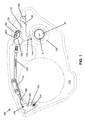
- FIG. 1 illustrates a side view of a narrow transmission 100 including a park lock device, the park lock device in a "not parked" mode or position
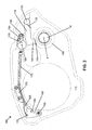
- FIG. 2 illustrates a side view of narrow transmission 100 including the park lock device in a "parked” mode or position.
- the park lock device is a mechanical interlock that selectively engages with and disengages from a park lock gear 105.
- Park lock gear 105 includes a rotational axis A which rotates together with a motor axis M within a transmission case, motor axis M coupled in turn to a wheel axis of a vehicle.
- the transmission case includes a pair of complementary mating half cases, a back half case 110 shown in FIG. 1 .
- the park lock device includes a cooperating set of components: a park pawl 115, a park rod 120, a park sleeve 125, a pawl torsional spring 130, and a pawl stopper 135. These components move within a single plane defined by the transmission case and are supported by the transmission case as further described herein.
- Park lock gear 105 includes an outside diameter perimeter having a number N of distributed uniform concave portions 140. Concave portions 140 cooperate with a pawl portion 145 of park pawl 115 for producing the modes described herein, those modes including the parked mode and the not parked mode. Park pawl 115 rotates about a pawl shaft 150 when pawl portion 145 engages with, and disengages from, concave portions 140.
- park rod 120 The engaging/disengaging rotation of park pawl 115 is initiated by a movement of park rod 120.
- park rod 120 and park pawl 115 make contact inside of park sleeve 125, with the consequence that the park lock device enters into one of its modes (as further determined by the operational state of the other components of narrow transmission 100).
- the movement of park rod 120 is responsive to a controller (not shown) that commands one of the parked mode and the not parked mode for narrow transmission 100.
- a controller (not shown) that commands one of the parked mode and the not parked mode for narrow transmission 100.
- a software-controlled electromagnetic rotary actuator controls a rotation of a control shaft 155.
- Control shaft 155 rotates between a not parked position (in FIG. 1 ) and a parked position ( FIG. 2 ).
- Control shaft 155 rotates when making these transitions between parked and not parked positions, however due to the nature of such electromechanical actuators, control shaft 155 sometimes does not exactly rotate.
- Narrow transmission 100 compensates for any inexact rotation by mechanically limiting/finishing rotation of control shaft 155 by use of a detent plate 160.
- Detent plate 160 includes a cam profile with two detents, one detent corresponding to the park position and one detent corresponding to the not parked position. The cam profile includes a number of curves and slopes joining the two detents.
- a detent spring 165 includes a cam profile follower 170 that limits any over rotation of control shaft 155 in both rotational directions due to physical stops at outside edges of the detents. Cam profile follower 170 inhibits any under rotation of control shaft 155 in both directions by either finishing a rotational transition or returning control shaft to its pre-transition position. The specifics are determined by the amount of actual rotation of control shaft 155 and where cam profile follower 170 is placed along the cam profile.
- Detent spring 165 exerts sufficient torque on control shaft 155 through interaction with detent plate 160 to follow the cam profile and rotate control shaft 155 until cam profile follower 170 engages one of the two detents.
- a required torque to actuate parked mode from not parked mode is kept below a minimum torque provided by detent plate 160 and interacting detent spring 165.
- the cam profile is not symmetric having a different set of conditions to transition from parked to not parked as compared to a set conditions to transition from not parked to parked.
- the curves and slopes of the cam profile are configured to provide the desired response to rotational uncertainty in control shaft 155 and a required amount of torque for detent spring 165 for those desired responses.
- detent spring 165 is a leaf spring mounted laterally from back half case 110 using a support 175 rather than having detent spring 165 mounted directly to the transmission case on the top or bottom surface of the spring in a conventional fashion.
- the particular configuration of detent spring 165 provides the necessary torques for cam profile follower 170 to affect movement of detent plate 160 while being sufficiently rigidly supported.
- a proximal end 180 of park rod 120 includes a ninety degree bend provided with swaged elements to engage rotationally a mating aperture on detent plate 160. Engagement/disengagement of the swaged end with detent plate 160 requires a rotation of control shaft 155 beyond the detent positions and therefore the swaged elements prevent accidental disengagement during operation.
- proximal end 180 to detent plate 160 converts rotation of control shaft 155 to lateral translation of park rod 120.
- a distal end of park rod 120 (not shown in FIG. 1 because park rod 120 terminates within park sleeve 125) converts translation of park rod 120 into mechanical control of park pawl 115 as further described below.
- Pawl torsional spring 130 coupled to pawl shaft 150, rotationally biases park pawl 115 upwards and away from engagement with park lock gear 105. The translation of park rod 120 overcomes this bias in appropriate situations to rotate park pawl 115 downwards toward engagement with park lock gear 105.
- Park sleeve 125 includes a cylindrical perimeter and rotates about a transverse axis 185 relative to back half case 110. This rotation of park sleeve 125 allows self-alignment in response to internal interactions of park rod 120 and park pawl 115. A magnitude of rotation of park sleeve 125 is limited by a bracket 190 coupled to a complementary external cutout in park sleeve 125.
- Pawl stopper 135 also includes a generally cylindrical perimeter and rotates about a transverse axis relative to back half case 110. This rotation of pawl stopper 135 allows self alignment in response to impacts of park pawl 115. A magnitude of rotation of pawl stopper 135 is limited by bracket 190 coupled to a complementary external cutout in pawl stopper 135. Bracket 190 thus concurrently retains both park sleeve 125 and pawl stopper 135 while permitting both structures to independently self-align to help meet space and weight budgets.
- transverse axis 185, the transverse axis of pawl stopper 135, a rotational axis of pawl shaft 150, and a rotational axis of control shaft 155 are all parallel.
- a manufacturing and assembly advantage of the disclosed embodiment of the present invention is that these elements engage and rotate within parallel bores disposed in back half case 110.
- a milling machine would be able to create all these bores in a single pass without removing/repositioning back half case 110 in between creation of some of the bores. This means that all of the bores are all accurately positioned relative to each other. This improves assembly accuracy as the functional positions of these components are fixed without use of other parts. In contrast, if this assembly required machining in multiple planes, the resulting accuracy of those assembly would be less than an assembly able to be machined in a single plane.
- park sleeve 125 One critical component is positioning and operation of park sleeve 125. Because park sleeve has a cylindrical perimeter it is easily installed into back half case 110 by inserting it into one of these accurately positioned bores. No other parts or brackets are needed to determine the operational position of park sleeve. The assembly is simplified in this fashion because no high accuracy position fixing bracket is required (such brackets can be complicated and possibly more expensive). A loose tolerance anti-rotation alignment bracket that limits rotation of park sleeve 125 replaces any position fixing bracket.
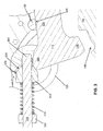
- FIG. 3 illustrates a sectional view of a portion of the park lock device of FIG. 1 depicting an interaction of park rod 120 and park pawl 115 inside park sleeve 125 (not parked mode)
- FIG. 4 illustrates a sectional view of a portion of the park lock device of FIG. 2 depicting an interaction of park rod 120 and park pawl 115 inside park sleeve 125 (parked mode)
- FIG. 5 illustrates a sectional view of a portion of the park lock device detailing component orientation during transitions between the not parked mode of FIG. 1 and the parked mode of FIG. 2 .
- Park rod 120 includes a distal end 305 (e.g., a tip of park rod 120) opposite from proximal end 180 with a cam portion 310 disposed at distal end 305 and secured with an end stop.
- Cam portion 310 slidingly engages distal end 305 to move along park rod 120 between an extended position and a compressed position.
- cam portion 310 includes two sloped portions: a steep forward portion 325 and a shallower rearward portion 330 (while appearing flat, in actuality these surfaces are radially symmetric).
- Park pawl 115 includes pawl portion 145 at a distal end away from pawl shaft 150. Pawl portion 145 locks park lock gear 105 by engaging one uniform concave portion 140. Park pawl 115 further includes a body portion 335 joining pawl shaft 150 to the distal end and a cam contact portion 340 also at the distal end opposing pawl portion 145. Body portion 335 is laterally flat with pawl stopper 135 including a complementary flat chord 345 disposed on an intermediate portion of its cylindrical outer surface (that engages back half case 11), flat chord 345 rotating to align with body portion 335 when pawl stopper 135 is impacted by body portion 335.
- park sleeve 125 includes an internal cam follower portion 405 that contacts cam portion 310 at a first contact point 410 along the slopes of cam portion 310.
- First contact point 410 moves along cam portion 310 as cam portion 310 moves in and out of park sleeve 125.
- Cam contact portion 340 contacts cam portion 310 at a second contact point 415 along the slopes of cam portion 310.
- Second contact point 415 moves along cam portion 310 as cam portion 310 moves in and out of park sleeve 125 and park pawl 115 rotates.
- Park rod 120 is cylindrical at proximal end 180 and distal end 305, distal end 305 including a longitudinal axis 420.
- a line of action passes approximately through the transverse axis which is approximately passed through the center of park sleeve 125.
- Longitudinal axis 420 is perpendicular to both a first imaginary line extending between transverse axis 185 and first contact point 410 as well as a second imaginary line extending between transverse axis 185 and second contact point 415.
- This configuration provides that the resulting moment on park sleeve 125 is zero regardless of an angle that rearward portion 330 makes at first contact point 410, a distance from transverse axis 185 to first contact point 410 or a magnitude of a force F at first contact point 410. Further, park sleeve 125 self-aligns so that the distance from transverse axis 185 to first contact point 410 matches a distance from transverse axis 185 to second contact point 415. Due to the resulting symmetric loading with respect to longitudinal axis 420 the resultant moment is also zero. Configuring park sleeve 125 and park rod 120 for relative self-alignment in park mode in this way provides two mechanisms to produce a zero resultant moment that reduces unnecessary stress on the park lock device.
- Both park sleeve 125 and pawl stopper 135 rotate for self-alignment, with bracket 190 used for both retaining them within back half case 110 at about the proper alignment and limiting the magnitudes of their rotations during self-alignments.
- Bracket 190 attaches to back half case 110 to "trap" park sleeve 125 and pawl stopper 135 while the external cuts on outside edges of park sleeve 125 and pawl stopper 135 engage bracket 190 to provide the rotation limitation.
- the park sleeve 125 rotation range allows for cam portion 310 to freely enter and exit during transitions of the park lock device between modes.
- Pawl stopper 135 rotation range allows for impacts by body portion 335 to rotate pawl stopper 135 so flat chord 345 is substantially parallel to body portion 335.
- the park lock device transitions from the not parked mode shown in FIG. 1 to the parked mode shown in FIG. 2 and transitions from the parked mode to the not parked mode as determined by the controller.
- the controller causes control shaft 155 to rotate clockwise (in FIG. 1 ) which translates park rod 120 to the right and causes cam portion 310 to more fully enter into park sleeve 125.
- forward portion 325 of cam portion 310 engages both cam follower portion 405 of park sleeve 125 and cam contact portion 340 of park pawl 115.
- park pawl 115 rotates park pawl 115 counterclockwise (downward in FIG. 5 ) since forward portion 325 engages both park sleeve 125 and park pawl 115.
- park pawl 115, park sleeve 125, and cam portion 310 have the relationship shown in FIG. 4 in which rearward portion 330 of cam portion 310 engages both park sleeve 125 and park pawl 115 in the parked mode.
- the park lock device is configured as shown in FIG.
- park pawl 115 cannot disengage from park lock gear 105 and forces exerted on cam portion 310 by park pawl 115 are not capable of translating park rod 120 to the left to enable disengagement. Only by translation of park rod 120 to the left, such as by rotation of control shaft 155 counterclockwise, will cam portion 310 transition to the intermediate mode shown in FIG. 5 to enable park pawl 115 to rotate clockwise (upwards in FIG. 4 ) and disengage from park lock gear 105.
- FIG. 6 illustrates a sectional view of a portion of the park lock device detailing an operational mode with the controller in the parked position prior to the parking pawl engaging the park gear.
- the park lock device automatically enters into the park mode in normal fashion as described herein.
- FIG. 7 illustrates a side view of park rod 120
- FIG. 8 illustrates a top view of park rod 120
- FIG. 9 illustrates a sectional view of a mid-portion of park rod 120 about A-A identified in FIG. 7
- park pawl 115 can impart significant bending/buckling loads to park rod 120.
- Park rod 120 includes a mid-portion that has a cross-section which is generally oblong-shaped. The oblong having a major axis that is vertical. This oblong-shaped cross-section helps enable park rod 120 to better endure such skid torque mode.
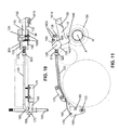
- FIG. 10 illustrates a top view of the park lock device components from FIG. 2 (park mode) isolated from the transmission case; and FIG. 11 illustrates a side view of the park lock device components of FIG. 10 .
- a pair of bolts 1005 is shown securing bracket 190 in place.
- an enlarged head 1010 for pawl shaft 150 is also illustrated. Enlarged head 1010 interacts with a second half of the transmission case (not shown) that holds pawl shaft 150 in place while permitting it to freely turn. In this way no additional retention or mounting hardware is required, saving weight and decreasing component count.
- FIG. 12 illustrates an end view of park sleeve 125 detailing an opening 1205 receiving cam portion 310 of parking rod 120; and FIG. 13 illustrates an isometric view of park sleeve 125 including receipt of cam portion 310 within opening 1205.
- Parking rod 120 reciprocates in and out of opening 1205 with cam portion 310 engaging cam follower portion 405.
- opening 1205 is provided with an upper stopper 1210 and a pair of side-to-side guides 1215.
- Upper stopper 1210 and side-to-side guides 1215 engage distal end 305 shown in FIG. 3 as it reciprocates to maintain operational alignment within the plane of the transmission.
- Opening 1205 does not include a lower stopper and is open opposite of cam follower portion 405 because cam contact portion 340 of park pawl 115 is located at this position.
- park sleeve 125 sandwiches park pawl 115 (i.e., cam contact portion 340) and surrounds cam portion 310 with the aid of park pawl 115.
- Distal end 305 is guided and aligned without use of additional parts as is sometimes required in conventional systems.
Landscapes
- Engineering & Computer Science (AREA)
- Mechanical Engineering (AREA)
- General Engineering & Computer Science (AREA)
- Transportation (AREA)
- Gear-Shifting Mechanisms (AREA)
Claims (16)
- Parksperrvorrichtung für schmale Getriebe, (100), mit:einem in einem Getriebegehäuse an einer sich gemeinsam mit einer Radachse drehenden Drehachse vorgesehenen Parkmechanismus;einer in dem Getriebegehäuse dergestalt vorgesehenen Parkklinke, dass sie um eine an einem proximalen Ende der Parkklinke gekoppelte Klinkenwelle (150) rotiert, wobei die Parkklinke einen Klinkenabschnitt an einem distalen Ende aufweist, der den Parkmechanismus durch ein ineinander Eingreifen verriegelt, wobei die Parkklinke des Weiteren einen Körperabschnitt umfasst, der das proximale Ende mit dem distalen Ende koppelt und einen Nockenkontaktabschnitt an dem distalen Ende gegenüber dem Klinkenabschnitt;einem in dem Getriebegehäuse dergestalt vorgesehenen Parkgestänge (120), dass es sich gemeinsam mit einer Operation eines Controllers bewegt, wobei das Parkgestänge einen Nockenabschnitt aufweist, der gegen den Nockenkontaktabschnitt der Parkklinke drückt, um das Eingreifen zwischen dem Klinkenabschnitt der Parkklinke und dem Parkmechanismus gemäß der Operation des Controllers durchzuführen;einer Parkbuchse (125) zum Aufnehmen des Nockenabschnitts des Parkgestänges und Definieren eines ersten Kontaktpunkts zum Bereitstellen einer Reaktionskraft auf den Nockenkontaktabschnitt der an einem zweiten Kontaktpunkt gegen den Nockenabschnitt des Parkgestänges drückenden Parkklinke;einer mit der Parkklinke gekoppelten Klinkentorsionsfeder (130), die eine Drehung der Parkklinke um die Klinkenwelle in Richtung eines Lösens des Parkmechanismus von dem Klinkenabschnitt vorspannt, um den Parkmechanismus zu entriegeln; undeinem in dem Getriebegehäuse vorgesehenen Klinkenstopper (135) zum Begrenzen der Drehung der Parkklinke durch Kontaktieren des Körperabschnitts der Parkklinke; dadurch gekennzeichnet, dasseine Bewegung des Parkmechanismus, der Parkklinke und des Parkgestänges in einer vertikalen Ebene des Getriebegehäuses begrenzt ist.
- Parksperrvorrichtung nach Anspruch 1, wobei das Getriebegehäuse einen hinteren Abschnitt und einen vorderen Abschnitt umfasst, wobei ein bestimmter Abschnitt eine Vielzahl von Bohrungen umfasst, wobei jede der Bohrungen eine im Wesentlichen parallel zueinander verlaufende Bohrungsachse umfasst, und wobei die Klinkenwelle, die Parkbuchse und der Klinkenstopper jeweils eine zylindrische Außenoberfläche und eine Drehachse umfassen, wobei die zylindrische Außenoberfläche in eine der Vielzahl von Bohrungen eingreift und die Drehachse parallel zu den Bohrungsachsen verläuft.
- Parksperrvorrichtung nach Anspruch 1, wobei der Controller eine Steuerwelle umfasst, die sich zwischen einer Parkposition und einer Nichtparkposition dreht, wobei die Parksperrvorrichtung des Weiteren umfasst:eine mit der Steuerwelle gekoppelte Sperrplatte, wobei die Sperrplatte ein Nockenprofil mit einer Parkpositionssperre und einer Nichtparkpositionssperre definiert, die jeweils gewünschten Drehpositionen für die Parkposition beziehungsweise die Nichtparkposition der Steuerwelle entsprechen; undeine Sperrfeder, die mit der Sperrplatte gekoppelt ist und mit dem Nockenprofil zusammenwirkt, um die Steuerwelle in eine der Positionen zu drehen;wobei der Nockenabschnitt des Parkgestänges gleitend eine Spitze des Parkgestänges in Eingriff bringt, um sich entlang des Parkgestänges zwischen einer verlängerten Position und einer komprimierten Position zu bewegen,wobei der Nockenabschnitt in Richtung der Spitze vorgespannt ist und wobei der Nockenabschnitt zu der komprimierten Position zurückgefahren ist, wenn sich der Controller in der Parkverriegelungsposition befindet und der Klinkenabschnitt von dem Parkmechanismus gelöst ist; undwobei das Parkgestänge ein mit der Sperrplatte gekoppeltes proximales Ende, ein mit der Spitze gekoppeltes distales Ende und einen sich dazwischen erstreckenden Körperabschnitt umfasst, wobei die Enden einen im Wesentlichen kreisförmigen Querschnitt aufweisen und der Körperabschnitt einen im Wesentlichen rechteckigen Querschnitt aufweist, wobei der im Wesentlichen rechteckige Querschnitt eine vertikal angeordnete Hauptsymmetrieachse aufweist.
- Parksperrvorrichtung nach Anspruch 1, wobei die Parkbuchse einen zylindrischen Umfang in einer Richtung quer zu dem Getriebegehäuse umfasst, wobei die Parkbuchse um eine erste Querachse drehbar ist, um sich im Ansprechen auf ein Kontaktieren des ersten Kontaktpunkts durch den Nockenabschnitt selbst auszurichten.
- Parksperrvorrichtung nach Anspruch 4, wobei die Parkbuchse sich so selbst ausrichtet, dass eine Aktionslinie der Parknocke im Wesentlichen senkrecht zu einer ersten Linie verläuft, die den ersten Kontaktpunkt mit der ersten Querachse verbindet und im Wesentlichen senkrecht zu einer zweiten Linie verläuft, die den zweiten Kontaktpunkt mit der ersten Querachse verbindet.
- Parksperrvorrichtung nach Anspruch 5, wobei ein erster Abstand von dem ersten Kontaktpunkt zu der ersten Querachse im Wesentlichen mit einem zweiten Abstand von dem zweiten Kontaktpunkt zu der Querachse übereinstimmt.
- Parksperrvorrichtung nach Anspruch 1, wobei der Körperabschnitt der Parkklinke den Klinkenstopper an einem Körperkontaktpunkt kontaktiert und wobei der Klinkenstopper eine im Wesentlichen zylindrische Außenoberfläche aufweist, die senkrecht zu einer äußeren Wand des Getriebegehäuses verläuft, wobei die im Wesentlichen zylindrische Außenoberfläche in die Außenwand eingreift, wobei ein Klinkenkontaktabschnitt des Klinkenstoppers durch einen flachen Trägerflanschabschnitt des Klinkenstoppers definiert ist, wobei die Klinkenbuchse zur Selbstausrichtung um eine zweite Querachse drehbar ist im Ansprechen auf ein Kontaktieren des Klinkenkontaktabschnitts des Klinkenstoppers durch den Körperabschnitt der Klinke, sodass der flache Trägerflanschabschnitt an dem Körperkontaktpunkt im Wesentlichen parallel zu dem Klinkenkörper verläuft.
- Parksperrvorrichtung nach Anspruch 6, wobei der Körperabschnitt der Parkklinke den Klinkenstopper an einem Körperkontaktpunkt kontaktiert und wobei der Klinkenstopper eine im Wesentlichen zylindrische Außenoberfläche senkrecht zu einer Außenwand des Getriebegehäuses aufweist, wobei die im Wesentlichen zylindrische Außenoberfläche in die Außenwand eingreift, wobei ein Klinkenkontaktabschnitt des Klinkenstoppers durch einen flachen Trägerflanschabschnitt des Klinkenstoppers definiert ist, wobei die Klinkenbuchse zur Selbstausrichtung um eine zweite Querachse drehbar ist im Ansprechen auf ein Kontaktieren des Klinkenkontaktabschnitts des Klinkenstoppers durch den Körperabschnitt der Klinke, sodass der flache Trägerflanschabschnitt an dem Körperkontaktpunkt im Wesentlichen parallel zu dem Klinkenkörper verläuft.
- Parksperrvorrichtung nach Anspruch 8, des Weiteren umfassend ein Halteelement zum Halten sowohl der Parkbuchse als auch des Parkstoppers an dem Getriebegehäuse unter Zulassung einer Selbstausrichtung der Parkbuchse um die erste Querachse und unter Zulassung einer Selbstausrichtung des Klinkenstoppers um die zweite Querachse.
- Parksperrvorrichtung nach Anspruch 1, wobei sich die Klinkenwelle frei zwischen dem Eingreifen und dem Lösen bewegt, wobei die Klinkenwelle in einer Bohrung einer ersten Hälfte des Getriebegehäuses angeordnet ist, wobei die Klinkenwelle einen mit einer zweiten Hälfte des Getriebegehäuses kooperierenden Kopf aufweist zum Rückhalten der Klinkenwelle innerhalb der Bohrung.
- Parksperrvorrichtung nach Anspruch 1, wobei ein Umfang des Parkmechanismus eine Anzahl N von verteilten konkaven Abschnitten definiert, wobei jeder konkave Abschnitt ein gleichförmiges Profil aufweist, wobei der Klinkenabschnitt für das Eingreifen in einen der konkaven Abschnitte eingreift.
- Parksperrvorrichtung nach Anspruch 11, wobei der Nockenabschnitt des Parkgestänges gleitend in eine Spitze des Parkgestänges eingreift, um entlang des Parkgestänges zwischen einer verlängerten Position und einer komprimierten Position zu wandern, wobei der Nockenabschnitt in Richtung der Spitze vorgespannt ist, und wobei der Nockenabschnitt ein Nockenabschnittprofil aufweist, das einen steilen Anstieg in Richtung der Spitze und einen flachen Anstieg an der Innenseite des steilen Anstiegs aufweist, wobei die Kontaktpunkte für das Eingreifen des Parkmechanismus in den flachen Anstieg eingreifen, und wobei die Kontaktpunkte in den steilen Anstieg eingreifen, wenn sich der Controller in der verriegelten Position befindet und sich der Klinkenabschnitt mit keinem der konkaven Abschnitte im Eingriff befindet.
- Parksperrvorrichtung nach Anspruch 1, wobei die Parkbuchse eine Öffnung aufweist, die durch einen oberen Wandabschnitt und ein Paar lateraler Wandabschnitte definiert ist, wobei die Öffnung sowohl den Nockenabschnitt als auch den Nockenkontaktabschnitt der Parkklinke aufnimmt, um den Nockenabschnitt und die Parkklinke zwischen das Paar lateraler Wandabschnitte einzuschieben und sie in einem konzentrischen Kreis zu positionieren.
- Parksperrvorrichtung nach Anspruch 13, wobei der obere Wandabschnitt einen oberen Stopper aufweist und wobei jeder laterale Wandabschnitt eine Seitenführung aufweist, wobei der obere Stopper und die Seitenführungen die Spitze des Parkgestänges führen, wenn das Parkgestänge in die Öffnung eintritt.
- Parksperrvorrichtung nach Anspruch 3, wobei die Parkbuchse eine Öffnung aufweist, die durch einen oberen Wandabschnitt und ein Paar lateraler Wandabschnitte definiert ist, wobei die Öffnung sowohl den Nockenabschnitt als auch den Nockenkontaktabschnitt der Parkklinke aufnimmt, um den Nockenabschnitt und die Parkklinke zwischen das Paar lateraler Wandabschnitte einzuschieben und sie in einem konzentrischen Kreis zu positionieren.
- Parksperrverfahren für ein schmales Getriebegehäuse, wobei das Verfahren anspricht auf einen Controller zum selektiven Eingreifen eines Parkmechanismus, der zum Drehen in einer Ebene des schmalen Getriebegehäuses an einer Drehachse vorgesehen ist, die sich gemeinsam mit einer Radachse dreht, wobei das Verfahren umfasst:a) Bewegen eines Parkgestänges innerhalb der Ebene des schmalen Getriebegehäuses gemeinsam mit einer Operation des von dem Parkgestänge abgesetzt angeordneten Controllers, wobei das Parkgestänge einen Nockenabschnitt aufweist;b) Drücken des Nockenabschnitts gegen einen Nockenkontaktabschnitt einer innerhalb des engen Getriebegehäuses angeordneten Parkklinke zum Einrasten des Parkmechanismus, wenn die Operation des Controllers eine Parkbetriebsart anweist, wobei die Parkklinke innerhalb der Ebene um eine an einem proximalen Ende der Parkklinke angeordnete Klinkenwelle drehbar ist, wobei die Parkklinke einen Klinkenabschnitt an einem distalen Ende aufweist, der in der Parkbetriebsart in den Parkmechanismus eingreift, wobei der Nockenkontaktabschnitt auch an dem distalen Ende gegenüber dem Klinkenabschnitt angeordnet ist und mit dem Nockenabschnitt innerhalb einer selbstausrichtenden drehbaren Parkbuchse zusammenwirkt;c) Lösen des Nockenabschnitts von dem Nockenkontaktabschnitt der Parkklinke, um den Parkmechanismus loszulassen, wenn die Operation des Controllers eine Nichtparkbetriebsart anweist; undd) Drehen der Parkklinke zum Lösen des Klinkenabschnitts von dem Parkmechanismus im Ansprechen auf eine zum Lösen vorgespannte Torsionsfeder, die mit der Klinkenwelle gekoppelt ist, nachdem der Nockenabschnitt von dem Nockenkontaktabschnitt gelöst wurde, wobei ein selbstausrichtender Klinkenstopper drehbar in der Nähe eines Körperabschnitts der Parkklinke angeordnet ist, um die lösende Drehung der Parkklinke zu begrenzen, wobei der Körperabschnitt das proximale Ende und das distale Ende verbindet.
Applications Claiming Priority (1)
| Application Number | Priority Date | Filing Date | Title |
|---|---|---|---|
| US13/460,349 US8881883B2 (en) | 2012-04-30 | 2012-04-30 | Park lock for narrow transmission |
Publications (2)
| Publication Number | Publication Date |
|---|---|
| EP2660112A1 EP2660112A1 (de) | 2013-11-06 |
| EP2660112B1 true EP2660112B1 (de) | 2014-12-17 |
Family
ID=48190817
Family Applications (1)
| Application Number | Title | Priority Date | Filing Date |
|---|---|---|---|
| EP13165964.1A Active EP2660112B1 (de) | 2012-04-30 | 2013-04-30 | Parksperre für schmale Übertragung |
Country Status (2)
| Country | Link |
|---|---|
| US (1) | US8881883B2 (de) |
| EP (1) | EP2660112B1 (de) |
Families Citing this family (28)
| Publication number | Priority date | Publication date | Assignee | Title |
|---|---|---|---|---|
| JP6137868B2 (ja) * | 2013-02-25 | 2017-05-31 | 住友重機械工業株式会社 | パーキングブレーキ装置 |
| US9255640B1 (en) * | 2014-09-03 | 2016-02-09 | E-Aam Driveline Systems Ab | Park lock mechanism |
| CN104455395B (zh) * | 2014-11-27 | 2017-11-28 | 长城汽车股份有限公司 | 车辆驻车装置及其运行的控制方法和车辆 |
| WO2017038208A1 (ja) * | 2015-08-28 | 2017-03-09 | アイシン・エィ・ダブリュ株式会社 | パーキング装置およびその組立方法 |
| FR3060091B1 (fr) * | 2016-12-09 | 2018-11-30 | Renault S.A.S. | Dispositif de blocage mecanique d'un arbre de transmission d'un vehicule automobile |
| DE102017203346A1 (de) * | 2016-12-21 | 2018-06-21 | Volkswagen Aktiengesellschaft | Parksperrenaktuator für ein Kraftfahrzeuggetriebes und ein Verfahren zur Steuerung des Parksperrenaktuators |
| KR102370495B1 (ko) * | 2017-02-22 | 2022-03-07 | 현대자동차주식회사 | 차량용 파킹장치 |
| US11247548B2 (en) * | 2017-05-25 | 2022-02-15 | Dana Heavy Vehicle Systems Group, Llc | Modular head assembly for an electric axle |
| CN107859739B (zh) * | 2017-10-23 | 2020-08-18 | 北京新能源汽车股份有限公司 | P挡驻车机构和车辆 |
| CN107859740B (zh) * | 2017-10-23 | 2020-04-10 | 北京新能源汽车股份有限公司 | P挡驻车机构和车辆 |
| CN107725765B (zh) * | 2017-10-23 | 2020-06-12 | 北京新能源汽车股份有限公司 | P挡驻车机构和车辆 |
| US11473678B2 (en) | 2018-06-13 | 2022-10-18 | Vitesco Technologies USA, LLC | Electric park lock actuator limited rotary disconnect |
| JP2022523625A (ja) | 2019-01-07 | 2022-04-26 | カヌー テクノロジーズ インク | バッテリーパック熱管理の方法およびシステム |
| JP6807974B2 (ja) * | 2019-03-20 | 2021-01-06 | 本田技研工業株式会社 | 車両用パーキング装置 |
| US11833895B2 (en) | 2019-05-20 | 2023-12-05 | Canoo Technologies Inc. | Electric vehicle platform |
| US12420869B2 (en) | 2019-07-02 | 2025-09-23 | Canoo Technologies Inc. | Method to reduced lateral deflection of longitudinal members in side impact |
| CA3145383C (en) | 2019-07-02 | 2025-05-27 | Canoo Technologies Inc. | SHOCK FEATURES |
| WO2021050605A1 (en) * | 2019-09-09 | 2021-03-18 | Canoo Inc. | Suspension system |
| CA3163499C (en) | 2019-09-20 | 2024-11-05 | Canoo Technologies Inc. | VEHICLE SEATING SYSTEMS |
| WO2021055980A1 (en) | 2019-09-20 | 2021-03-25 | Canoo Inc. | Electric vehicle battery enclosure |
| JP7400308B2 (ja) * | 2019-09-30 | 2023-12-19 | ニデック株式会社 | パーキングロック装置およびそれを備えたモータユニット |
| JP7413698B2 (ja) * | 2019-09-30 | 2024-01-16 | ニデック株式会社 | パーキングロック装置およびそれを備えたモータユニット |
| CN110920589B (zh) * | 2019-12-03 | 2021-01-26 | 株洲齿轮有限责任公司 | 电子驻车挡自学习方法、电子驻车方法、控制器及车辆 |
| CN111336250B (zh) * | 2020-03-10 | 2022-03-04 | 南京美均电子科技有限公司 | 一种驻车执行器位置学习方法 |
| CN111412280A (zh) * | 2020-03-27 | 2020-07-14 | 广州小鹏汽车科技有限公司 | 电动汽车及其p挡控制方法 |
| CN113958707B (zh) * | 2020-07-20 | 2023-04-07 | 上海汽车集团股份有限公司 | 电控p挡驻车装置及汽车 |
| JP7567512B2 (ja) * | 2021-01-29 | 2024-10-16 | ニデック株式会社 | パーキング機構、および駆動装置 |
| US11719337B2 (en) | 2021-03-26 | 2023-08-08 | Dana Heavy Vehicle Systems Group, Llc | Methods and systems for a parking mechanism |
Family Cites Families (5)
| Publication number | Priority date | Publication date | Assignee | Title |
|---|---|---|---|---|
| JPS59184049A (ja) * | 1983-03-31 | 1984-10-19 | Aisin Seiki Co Ltd | 変速機のパ−キング機構 |
| JP4281841B1 (ja) | 2008-02-07 | 2009-06-17 | 三菱自動車工業株式会社 | 車両用変速機 |
| DE102008011115A1 (de) | 2008-02-26 | 2009-08-27 | Schaeffler Kg | Getriebesperrvorrichtung |
| US8668067B2 (en) | 2009-08-27 | 2014-03-11 | Toyota Jidosha Kabushiki Kaisha | Vehicle parking lock device |
| KR20120063774A (ko) | 2010-12-08 | 2012-06-18 | 현대자동차주식회사 | 하이브리드 차량용 파킹 시스템 |
-
2012
- 2012-04-30 US US13/460,349 patent/US8881883B2/en active Active
-
2013
- 2013-04-30 EP EP13165964.1A patent/EP2660112B1/de active Active
Also Published As
| Publication number | Publication date |
|---|---|
| EP2660112A1 (de) | 2013-11-06 |
| US8881883B2 (en) | 2014-11-11 |
| US20130284559A1 (en) | 2013-10-31 |
Similar Documents
| Publication | Publication Date | Title |
|---|---|---|
| EP2660112B1 (de) | Parksperre für schmale Übertragung | |
| RU2408810C2 (ru) | Механизм блокировки механического блокирующегося дифференциала | |
| EP3279523B1 (de) | Betätigungseinheit zur steuerung der winkelposition eines steuerungselements, insbesondere für ein fahrzeuggetriebe | |
| JPH04228788A (ja) | 可逆ねじ及びナット作動装置及びこの装置を具備した引戸 | |
| EP3421700B1 (de) | Türbetätigungssystem, notöffnungsvorrichtung und isolierungsschloss für eine transitfahrzeugtür | |
| WO2011136049A1 (ja) | 車両用スライドレール装置 | |
| US11813908B2 (en) | Trailer hitch | |
| JP2019513922A (ja) | 家具駆動システム | |
| KR20210055107A (ko) | 차량의 출몰형 아웃사이드 도어 핸들 | |
| US20230279946A1 (en) | Transmission device | |
| US20110061483A1 (en) | Steering lock device | |
| US11623695B2 (en) | Vehicle pop-up hood apparatus | |
| EP1955922B1 (de) | Lenksäulenanordnung | |
| US20200166131A1 (en) | Parking lock and a transmission having the parking lock | |
| CN105383437A (zh) | 具有防盗锁的可调节的转向柱机构 | |
| FI126771B (fi) | Lukkorunko | |
| CN107725765B (zh) | P挡驻车机构和车辆 | |
| EP3412509B1 (de) | Betätigungsmechanismus für eine klappbare rückspiegelanordnung | |
| US11904932B2 (en) | Steering shaft for a steering column of a motor vehicle and steering column for a motor vehicle | |
| EP1800976B1 (de) | Elektrische schlossvorrichtung | |
| AU2021393852B2 (en) | Vehicle differential locking device | |
| KR101912381B1 (ko) | 디지털 도어락 | |
| CN212837235U (zh) | 一种门锁总成 | |
| JPH0452358B2 (de) | ||
| JP2008190187A (ja) | 錠装置 |
Legal Events
| Date | Code | Title | Description |
|---|---|---|---|
| PUAI | Public reference made under article 153(3) epc to a published international application that has entered the european phase |
Free format text: ORIGINAL CODE: 0009012 |
|
| AK | Designated contracting states |
Kind code of ref document: A1 Designated state(s): AL AT BE BG CH CY CZ DE DK EE ES FI FR GB GR HR HU IE IS IT LI LT LU LV MC MK MT NL NO PL PT RO RS SE SI SK SM TR |
|
| AX | Request for extension of the european patent |
Extension state: BA ME |
|
| 17P | Request for examination filed |
Effective date: 20140506 |
|
| RBV | Designated contracting states (corrected) |
Designated state(s): AL AT BE BG CH CY CZ DE DK EE ES FI FR GB GR HR HU IE IS IT LI LT LU LV MC MK MT NL NO PL PT RO RS SE SI SK SM TR |
|
| GRAP | Despatch of communication of intention to grant a patent |
Free format text: ORIGINAL CODE: EPIDOSNIGR1 |
|
| INTG | Intention to grant announced |
Effective date: 20140716 |
|
| GRAS | Grant fee paid |
Free format text: ORIGINAL CODE: EPIDOSNIGR3 |
|
| GRAA | (expected) grant |
Free format text: ORIGINAL CODE: 0009210 |
|
| AK | Designated contracting states |
Kind code of ref document: B1 Designated state(s): AL AT BE BG CH CY CZ DE DK EE ES FI FR GB GR HR HU IE IS IT LI LT LU LV MC MK MT NL NO PL PT RO RS SE SI SK SM TR |
|
| REG | Reference to a national code |
Ref country code: GB Ref legal event code: FG4D |
|
| REG | Reference to a national code |
Ref country code: CH Ref legal event code: EP |
|
| REG | Reference to a national code |
Ref country code: IE Ref legal event code: FG4D |
|
| REG | Reference to a national code |
Ref country code: AT Ref legal event code: REF Ref document number: 701646 Country of ref document: AT Kind code of ref document: T Effective date: 20150115 |
|
| REG | Reference to a national code |
Ref country code: DE Ref legal event code: R096 Ref document number: 602013000622 Country of ref document: DE Effective date: 20150212 |
|
| REG | Reference to a national code |
Ref country code: DE Ref legal event code: R082 Ref document number: 602013000622 Country of ref document: DE Representative=s name: BOEHMERT & BOEHMERT ANWALTSPARTNERSCHAFT MBB -, DE |
|
| PG25 | Lapsed in a contracting state [announced via postgrant information from national office to epo] |
Ref country code: LT Free format text: LAPSE BECAUSE OF FAILURE TO SUBMIT A TRANSLATION OF THE DESCRIPTION OR TO PAY THE FEE WITHIN THE PRESCRIBED TIME-LIMIT Effective date: 20141217 Ref country code: FI Free format text: LAPSE BECAUSE OF FAILURE TO SUBMIT A TRANSLATION OF THE DESCRIPTION OR TO PAY THE FEE WITHIN THE PRESCRIBED TIME-LIMIT Effective date: 20141217 Ref country code: NO Free format text: LAPSE BECAUSE OF FAILURE TO SUBMIT A TRANSLATION OF THE DESCRIPTION OR TO PAY THE FEE WITHIN THE PRESCRIBED TIME-LIMIT Effective date: 20150317 |
|
| REG | Reference to a national code |
Ref country code: LT Ref legal event code: MG4D |
|
| PG25 | Lapsed in a contracting state [announced via postgrant information from national office to epo] |
Ref country code: LV Free format text: LAPSE BECAUSE OF FAILURE TO SUBMIT A TRANSLATION OF THE DESCRIPTION OR TO PAY THE FEE WITHIN THE PRESCRIBED TIME-LIMIT Effective date: 20141217 Ref country code: GR Free format text: LAPSE BECAUSE OF FAILURE TO SUBMIT A TRANSLATION OF THE DESCRIPTION OR TO PAY THE FEE WITHIN THE PRESCRIBED TIME-LIMIT Effective date: 20150318 Ref country code: RS Free format text: LAPSE BECAUSE OF FAILURE TO SUBMIT A TRANSLATION OF THE DESCRIPTION OR TO PAY THE FEE WITHIN THE PRESCRIBED TIME-LIMIT Effective date: 20141217 Ref country code: SE Free format text: LAPSE BECAUSE OF FAILURE TO SUBMIT A TRANSLATION OF THE DESCRIPTION OR TO PAY THE FEE WITHIN THE PRESCRIBED TIME-LIMIT Effective date: 20141217 Ref country code: HR Free format text: LAPSE BECAUSE OF FAILURE TO SUBMIT A TRANSLATION OF THE DESCRIPTION OR TO PAY THE FEE WITHIN THE PRESCRIBED TIME-LIMIT Effective date: 20141217 |
|
| REG | Reference to a national code |
Ref country code: AT Ref legal event code: MK05 Ref document number: 701646 Country of ref document: AT Kind code of ref document: T Effective date: 20141217 |
|
| PG25 | Lapsed in a contracting state [announced via postgrant information from national office to epo] |
Ref country code: NL Free format text: LAPSE BECAUSE OF FAILURE TO SUBMIT A TRANSLATION OF THE DESCRIPTION OR TO PAY THE FEE WITHIN THE PRESCRIBED TIME-LIMIT Effective date: 20141217 |
|
| PG25 | Lapsed in a contracting state [announced via postgrant information from national office to epo] |
Ref country code: CZ Free format text: LAPSE BECAUSE OF FAILURE TO SUBMIT A TRANSLATION OF THE DESCRIPTION OR TO PAY THE FEE WITHIN THE PRESCRIBED TIME-LIMIT Effective date: 20141217 Ref country code: ES Free format text: LAPSE BECAUSE OF FAILURE TO SUBMIT A TRANSLATION OF THE DESCRIPTION OR TO PAY THE FEE WITHIN THE PRESCRIBED TIME-LIMIT Effective date: 20141217 Ref country code: EE Free format text: LAPSE BECAUSE OF FAILURE TO SUBMIT A TRANSLATION OF THE DESCRIPTION OR TO PAY THE FEE WITHIN THE PRESCRIBED TIME-LIMIT Effective date: 20141217 Ref country code: RO Free format text: LAPSE BECAUSE OF FAILURE TO SUBMIT A TRANSLATION OF THE DESCRIPTION OR TO PAY THE FEE WITHIN THE PRESCRIBED TIME-LIMIT Effective date: 20141217 Ref country code: SK Free format text: LAPSE BECAUSE OF FAILURE TO SUBMIT A TRANSLATION OF THE DESCRIPTION OR TO PAY THE FEE WITHIN THE PRESCRIBED TIME-LIMIT Effective date: 20141217 |
|
| PG25 | Lapsed in a contracting state [announced via postgrant information from national office to epo] |
Ref country code: AT Free format text: LAPSE BECAUSE OF FAILURE TO SUBMIT A TRANSLATION OF THE DESCRIPTION OR TO PAY THE FEE WITHIN THE PRESCRIBED TIME-LIMIT Effective date: 20141217 Ref country code: IS Free format text: LAPSE BECAUSE OF FAILURE TO SUBMIT A TRANSLATION OF THE DESCRIPTION OR TO PAY THE FEE WITHIN THE PRESCRIBED TIME-LIMIT Effective date: 20150417 Ref country code: PL Free format text: LAPSE BECAUSE OF FAILURE TO SUBMIT A TRANSLATION OF THE DESCRIPTION OR TO PAY THE FEE WITHIN THE PRESCRIBED TIME-LIMIT Effective date: 20141217 |
|
| REG | Reference to a national code |
Ref country code: DE Ref legal event code: R097 Ref document number: 602013000622 Country of ref document: DE |
|
| PLBE | No opposition filed within time limit |
Free format text: ORIGINAL CODE: 0009261 |
|
| STAA | Information on the status of an ep patent application or granted ep patent |
Free format text: STATUS: NO OPPOSITION FILED WITHIN TIME LIMIT |
|
| PG25 | Lapsed in a contracting state [announced via postgrant information from national office to epo] |
Ref country code: DK Free format text: LAPSE BECAUSE OF FAILURE TO SUBMIT A TRANSLATION OF THE DESCRIPTION OR TO PAY THE FEE WITHIN THE PRESCRIBED TIME-LIMIT Effective date: 20141217 |
|
| 26N | No opposition filed |
Effective date: 20150918 |
|
| PG25 | Lapsed in a contracting state [announced via postgrant information from national office to epo] |
Ref country code: MC Free format text: LAPSE BECAUSE OF FAILURE TO SUBMIT A TRANSLATION OF THE DESCRIPTION OR TO PAY THE FEE WITHIN THE PRESCRIBED TIME-LIMIT Effective date: 20141217 Ref country code: LU Free format text: LAPSE BECAUSE OF FAILURE TO SUBMIT A TRANSLATION OF THE DESCRIPTION OR TO PAY THE FEE WITHIN THE PRESCRIBED TIME-LIMIT Effective date: 20150430 |
|
| PG25 | Lapsed in a contracting state [announced via postgrant information from national office to epo] |
Ref country code: IT Free format text: LAPSE BECAUSE OF FAILURE TO SUBMIT A TRANSLATION OF THE DESCRIPTION OR TO PAY THE FEE WITHIN THE PRESCRIBED TIME-LIMIT Effective date: 20141217 |
|
| REG | Reference to a national code |
Ref country code: IE Ref legal event code: MM4A |
|
| PG25 | Lapsed in a contracting state [announced via postgrant information from national office to epo] |
Ref country code: SI Free format text: LAPSE BECAUSE OF FAILURE TO SUBMIT A TRANSLATION OF THE DESCRIPTION OR TO PAY THE FEE WITHIN THE PRESCRIBED TIME-LIMIT Effective date: 20141217 |
|
| REG | Reference to a national code |
Ref country code: FR Ref legal event code: PLFP Year of fee payment: 4 |
|
| PG25 | Lapsed in a contracting state [announced via postgrant information from national office to epo] |
Ref country code: IE Free format text: LAPSE BECAUSE OF NON-PAYMENT OF DUE FEES Effective date: 20150430 |
|
| PG25 | Lapsed in a contracting state [announced via postgrant information from national office to epo] |
Ref country code: BE Free format text: LAPSE BECAUSE OF FAILURE TO SUBMIT A TRANSLATION OF THE DESCRIPTION OR TO PAY THE FEE WITHIN THE PRESCRIBED TIME-LIMIT Effective date: 20141217 |
|
| REG | Reference to a national code |
Ref country code: CH Ref legal event code: PL |
|
| PG25 | Lapsed in a contracting state [announced via postgrant information from national office to epo] |
Ref country code: MT Free format text: LAPSE BECAUSE OF FAILURE TO SUBMIT A TRANSLATION OF THE DESCRIPTION OR TO PAY THE FEE WITHIN THE PRESCRIBED TIME-LIMIT Effective date: 20141217 |
|
| PG25 | Lapsed in a contracting state [announced via postgrant information from national office to epo] |
Ref country code: CH Free format text: LAPSE BECAUSE OF NON-PAYMENT OF DUE FEES Effective date: 20160430 Ref country code: LI Free format text: LAPSE BECAUSE OF NON-PAYMENT OF DUE FEES Effective date: 20160430 |
|
| REG | Reference to a national code |
Ref country code: FR Ref legal event code: PLFP Year of fee payment: 5 |
|
| PG25 | Lapsed in a contracting state [announced via postgrant information from national office to epo] |
Ref country code: BG Free format text: LAPSE BECAUSE OF FAILURE TO SUBMIT A TRANSLATION OF THE DESCRIPTION OR TO PAY THE FEE WITHIN THE PRESCRIBED TIME-LIMIT Effective date: 20141217 Ref country code: HU Free format text: LAPSE BECAUSE OF FAILURE TO SUBMIT A TRANSLATION OF THE DESCRIPTION OR TO PAY THE FEE WITHIN THE PRESCRIBED TIME-LIMIT; INVALID AB INITIO Effective date: 20130430 |
|
| PG25 | Lapsed in a contracting state [announced via postgrant information from national office to epo] |
Ref country code: CY Free format text: LAPSE BECAUSE OF FAILURE TO SUBMIT A TRANSLATION OF THE DESCRIPTION OR TO PAY THE FEE WITHIN THE PRESCRIBED TIME-LIMIT Effective date: 20141217 |
|
| PG25 | Lapsed in a contracting state [announced via postgrant information from national office to epo] |
Ref country code: TR Free format text: LAPSE BECAUSE OF FAILURE TO SUBMIT A TRANSLATION OF THE DESCRIPTION OR TO PAY THE FEE WITHIN THE PRESCRIBED TIME-LIMIT Effective date: 20141217 |
|
| REG | Reference to a national code |
Ref country code: FR Ref legal event code: PLFP Year of fee payment: 6 |
|
| PG25 | Lapsed in a contracting state [announced via postgrant information from national office to epo] |
Ref country code: SM Free format text: LAPSE BECAUSE OF FAILURE TO SUBMIT A TRANSLATION OF THE DESCRIPTION OR TO PAY THE FEE WITHIN THE PRESCRIBED TIME-LIMIT Effective date: 20141217 |
|
| PG25 | Lapsed in a contracting state [announced via postgrant information from national office to epo] |
Ref country code: MK Free format text: LAPSE BECAUSE OF FAILURE TO SUBMIT A TRANSLATION OF THE DESCRIPTION OR TO PAY THE FEE WITHIN THE PRESCRIBED TIME-LIMIT Effective date: 20141217 |
|
| PG25 | Lapsed in a contracting state [announced via postgrant information from national office to epo] |
Ref country code: PT Free format text: LAPSE BECAUSE OF FAILURE TO SUBMIT A TRANSLATION OF THE DESCRIPTION OR TO PAY THE FEE WITHIN THE PRESCRIBED TIME-LIMIT Effective date: 20141217 |
|
| PG25 | Lapsed in a contracting state [announced via postgrant information from national office to epo] |
Ref country code: AL Free format text: LAPSE BECAUSE OF FAILURE TO SUBMIT A TRANSLATION OF THE DESCRIPTION OR TO PAY THE FEE WITHIN THE PRESCRIBED TIME-LIMIT Effective date: 20141217 |
|
| REG | Reference to a national code |
Ref country code: DE Ref legal event code: R081 Ref document number: 602013000622 Country of ref document: DE Owner name: TESLA, INC., AUSTIN, US Free format text: FORMER OWNER: TESLA MOTORS INC., PALO ALTO, CALIF., US |
|
| P01 | Opt-out of the competence of the unified patent court (upc) registered |
Effective date: 20230512 |
|
| P02 | Opt-out of the competence of the unified patent court (upc) changed |
Effective date: 20230530 |
|
| PGFP | Annual fee paid to national office [announced via postgrant information from national office to epo] |
Ref country code: DE Payment date: 20250428 Year of fee payment: 13 |
|
| PGFP | Annual fee paid to national office [announced via postgrant information from national office to epo] |
Ref country code: GB Payment date: 20250422 Year of fee payment: 13 |
|
| PGFP | Annual fee paid to national office [announced via postgrant information from national office to epo] |
Ref country code: FR Payment date: 20250424 Year of fee payment: 13 |