EP2660366A1 - Siliciumcarbidsubstrat, halbleiterbauelement, verfahren zur herstellung des siliciumcarbidsubstrats und verfahren zur herstellung des halbleiterbauelements - Google Patents
Siliciumcarbidsubstrat, halbleiterbauelement, verfahren zur herstellung des siliciumcarbidsubstrats und verfahren zur herstellung des halbleiterbauelements Download PDFInfo
- Publication number
- EP2660366A1 EP2660366A1 EP11847883.3A EP11847883A EP2660366A1 EP 2660366 A1 EP2660366 A1 EP 2660366A1 EP 11847883 A EP11847883 A EP 11847883A EP 2660366 A1 EP2660366 A1 EP 2660366A1
- Authority
- EP
- European Patent Office
- Prior art keywords
- silicon carbide
- region
- emitting
- main surface
- semiconductor device
- Prior art date
- Legal status (The legal status is an assumption and is not a legal conclusion. Google has not performed a legal analysis and makes no representation as to the accuracy of the status listed.)
- Granted
Links
Images


Classifications
-
- H—ELECTRICITY
- H10—SEMICONDUCTOR DEVICES; ELECTRIC SOLID-STATE DEVICES NOT OTHERWISE PROVIDED FOR
- H10D—INORGANIC ELECTRIC SEMICONDUCTOR DEVICES
- H10D30/00—Field-effect transistors [FET]
- H10D30/60—Insulated-gate field-effect transistors [IGFET]
- H10D30/64—Double-diffused metal-oxide semiconductor [DMOS] FETs
- H10D30/66—Vertical DMOS [VDMOS] FETs
-
- H—ELECTRICITY
- H10—SEMICONDUCTOR DEVICES; ELECTRIC SOLID-STATE DEVICES NOT OTHERWISE PROVIDED FOR
- H10P—GENERIC PROCESSES OR APPARATUS FOR THE MANUFACTURE OR TREATMENT OF DEVICES COVERED BY CLASS H10
- H10P14/00—Formation of materials, e.g. in the shape of layers or pillars
- H10P14/20—Formation of materials, e.g. in the shape of layers or pillars of semiconductor materials
-
- C—CHEMISTRY; METALLURGY
- C30—CRYSTAL GROWTH
- C30B—SINGLE-CRYSTAL GROWTH; UNIDIRECTIONAL SOLIDIFICATION OF EUTECTIC MATERIAL OR UNIDIRECTIONAL DEMIXING OF EUTECTOID MATERIAL; REFINING BY ZONE-MELTING OF MATERIAL; PRODUCTION OF A HOMOGENEOUS POLYCRYSTALLINE MATERIAL WITH DEFINED STRUCTURE; SINGLE CRYSTALS OR HOMOGENEOUS POLYCRYSTALLINE MATERIAL WITH DEFINED STRUCTURE; AFTER-TREATMENT OF SINGLE CRYSTALS OR A HOMOGENEOUS POLYCRYSTALLINE MATERIAL WITH DEFINED STRUCTURE; APPARATUS THEREFOR
- C30B23/00—Single-crystal growth by condensing evaporated or sublimed materials
-
- C—CHEMISTRY; METALLURGY
- C30—CRYSTAL GROWTH
- C30B—SINGLE-CRYSTAL GROWTH; UNIDIRECTIONAL SOLIDIFICATION OF EUTECTIC MATERIAL OR UNIDIRECTIONAL DEMIXING OF EUTECTOID MATERIAL; REFINING BY ZONE-MELTING OF MATERIAL; PRODUCTION OF A HOMOGENEOUS POLYCRYSTALLINE MATERIAL WITH DEFINED STRUCTURE; SINGLE CRYSTALS OR HOMOGENEOUS POLYCRYSTALLINE MATERIAL WITH DEFINED STRUCTURE; AFTER-TREATMENT OF SINGLE CRYSTALS OR A HOMOGENEOUS POLYCRYSTALLINE MATERIAL WITH DEFINED STRUCTURE; APPARATUS THEREFOR
- C30B29/00—Single crystals or homogeneous polycrystalline material with defined structure characterised by the material or by their shape
- C30B29/10—Inorganic compounds or compositions
- C30B29/36—Carbides
-
- H—ELECTRICITY
- H10—SEMICONDUCTOR DEVICES; ELECTRIC SOLID-STATE DEVICES NOT OTHERWISE PROVIDED FOR
- H10D—INORGANIC ELECTRIC SEMICONDUCTOR DEVICES
- H10D12/00—Bipolar devices controlled by the field effect, e.g. insulated-gate bipolar transistors [IGBT]
- H10D12/01—Manufacture or treatment
- H10D12/031—Manufacture or treatment of IGBTs
-
- H—ELECTRICITY
- H10—SEMICONDUCTOR DEVICES; ELECTRIC SOLID-STATE DEVICES NOT OTHERWISE PROVIDED FOR
- H10D—INORGANIC ELECTRIC SEMICONDUCTOR DEVICES
- H10D62/00—Semiconductor bodies, or regions thereof, of devices having potential barriers
- H10D62/40—Crystalline structures
- H10D62/405—Orientations of crystalline planes
-
- H—ELECTRICITY
- H10—SEMICONDUCTOR DEVICES; ELECTRIC SOLID-STATE DEVICES NOT OTHERWISE PROVIDED FOR
- H10D—INORGANIC ELECTRIC SEMICONDUCTOR DEVICES
- H10D62/00—Semiconductor bodies, or regions thereof, of devices having potential barriers
- H10D62/80—Semiconductor bodies, or regions thereof, of devices having potential barriers characterised by the materials
- H10D62/83—Semiconductor bodies, or regions thereof, of devices having potential barriers characterised by the materials being Group IV materials, e.g. B-doped Si or undoped Ge
- H10D62/832—Semiconductor bodies, or regions thereof, of devices having potential barriers characterised by the materials being Group IV materials, e.g. B-doped Si or undoped Ge being Group IV materials comprising two or more elements, e.g. SiGe
- H10D62/8325—Silicon carbide
-
- H—ELECTRICITY
- H10—SEMICONDUCTOR DEVICES; ELECTRIC SOLID-STATE DEVICES NOT OTHERWISE PROVIDED FOR
- H10D—INORGANIC ELECTRIC SEMICONDUCTOR DEVICES
- H10D8/00—Diodes
- H10D8/01—Manufacture or treatment
- H10D8/051—Manufacture or treatment of Schottky diodes
-
- H—ELECTRICITY
- H10—SEMICONDUCTOR DEVICES; ELECTRIC SOLID-STATE DEVICES NOT OTHERWISE PROVIDED FOR
- H10D—INORGANIC ELECTRIC SEMICONDUCTOR DEVICES
- H10D8/00—Diodes
- H10D8/60—Schottky-barrier diodes
-
- H—ELECTRICITY
- H10—SEMICONDUCTOR DEVICES; ELECTRIC SOLID-STATE DEVICES NOT OTHERWISE PROVIDED FOR
- H10P—GENERIC PROCESSES OR APPARATUS FOR THE MANUFACTURE OR TREATMENT OF DEVICES COVERED BY CLASS H10
- H10P74/00—Testing or measuring during manufacture or treatment of wafers, substrates or devices
- H10P74/20—Testing or measuring during manufacture or treatment of wafers, substrates or devices characterised by the properties tested or measured, e.g. structural or electrical properties
- H10P74/203—Structural properties, e.g. testing or measuring thicknesses, line widths, warpage, bond strengths or physical defects
-
- G—PHYSICS
- G01—MEASURING; TESTING
- G01N—INVESTIGATING OR ANALYSING MATERIALS BY DETERMINING THEIR CHEMICAL OR PHYSICAL PROPERTIES
- G01N21/00—Investigating or analysing materials by the use of optical means, i.e. using sub-millimetre waves, infrared, visible or ultraviolet light
- G01N21/62—Systems in which the material investigated is excited whereby it emits light or causes a change in wavelength of the incident light
- G01N21/63—Systems in which the material investigated is excited whereby it emits light or causes a change in wavelength of the incident light optically excited
- G01N21/64—Fluorescence; Phosphorescence
- G01N21/6489—Photoluminescence of semiconductors
-
- H—ELECTRICITY
- H10—SEMICONDUCTOR DEVICES; ELECTRIC SOLID-STATE DEVICES NOT OTHERWISE PROVIDED FOR
- H10P—GENERIC PROCESSES OR APPARATUS FOR THE MANUFACTURE OR TREATMENT OF DEVICES COVERED BY CLASS H10
- H10P74/00—Testing or measuring during manufacture or treatment of wafers, substrates or devices
- H10P74/23—Testing or measuring during manufacture or treatment of wafers, substrates or devices characterised by multiple measurements, corrections, marking or sorting processes
Definitions
- the present invention relates to a silicon carbide substrate, a semiconductor device, a method of manufacturing a silicon carbide substrate, and a method of manufacturing a semiconductor device.
- a silicon carbide substrate has come to be used for manufacturing semiconductor devices as disclosed, for example, in United States Patent No. 7314520 (Patent Literature 1).
- silicon carbide has wider band-gap. Therefore, a semiconductor device using a silicon carbide substrate has advantages such as high breakdown voltage and low on-resistance and, in addition, its property does not much degrade in high-temperature environment.
- a forward direction in which current should flow and a reverse direction in which current should not flow are defined.
- the current flowing in the reverse direction, or reverse leakage current should be as small as possible. If a semiconductor device is manufactured using a silicon carbide substrate, however, the reverse leakage current tends to be large.
- an object of the present invention is to provide a silicon carbide substrate and a semiconductor device enabling reduction of reverse leakage current.
- the silicon carbide substrate in accordance with the present invention having a side surface and a main surface surrounded by the side surface, has a hexagonal crystal structure.
- the main surface is inclined by an off angle in an off direction from ⁇ 0001 ⁇ plane of the hexagonal crystal.
- the main surface has such a characteristic that, among the regions emitting photoluminescent light having a wavelength exceeding 650 nm of the main surface caused by excitation light having higher energy than band-gap of the hexagonal silicon carbide, the number of those having a dimension of at most 15 ⁇ m in a direction perpendicular to the off direction and a dimension in a direction parallel to the off direction not larger than a value obtained by dividing penetration length of the excitation light in the hexagonal silicon carbide by a tangent of the off angle is at most 1 ⁇ 10 4 per 1cm 2 .
- the emitting region may be a region emitting photoluminescent light having a wavelength exceeding 750 nm, or the emitting region may be a region emitting photoluminescent light having a wavelength exceeding 650 nm and shorter than 950 nm, or the emitting region may be a region emitting photoluminescent light having a wavelength exceeding 750 nm and shorter than 950 nm.
- the main surface has such a characteristic that the number of the emitting regions is at most 1 ⁇ 10 4 per 1 cm 2 .
- the silicon carbide substrate may include a silicon carbide layer having the main surface, and a base substrate supporting the silicon carbide layer.
- the silicon carbide layer is epitaxially formed on the base substrate.
- the semiconductor device in accordance with the present invention has the above-described silicon carbide substrate.
- the method of manufacturing a silicon carbide substrate in accordance with the present invention includes the following steps.
- a plurality of silicon carbide single crystals each having a main surface and a crystal structure of hexagonal crystal are prepared. Photoluminescence of the main surface of each of the plurality of silicon carbide single crystals is measured.
- the step of measuring photoluminescence includes the step of irradiating the main surface with excitation light having higher energy than band-gap of the hexagonal silicon carbide, and the step of observing emitting regions of photoluminescent light having a wavelength exceeding 650 nm caused by the excitation light.
- Crystal growth of silicon carbide is attained through sublimation method, using as a seed crystal one of the plurality of silicon carbide single crystals of which number of the emitting regions per unit area is smaller than a prescribed number.
- the emitting region may be a region emitting photoluminescent light having a wavelength exceeding 750 nm, or the emitting region may be a region emitting photoluminescent light having a wavelength exceeding 650 nm and shorter than 950 nm, or the emitting region may be a region emitting photoluminescent light having a wavelength exceeding 750 nm and shorter than 950 nm.
- the method of manufacturing a semiconductor device in accordance with the present invention includes the following steps.
- a plurality of silicon carbide substrates each having a main surface and a crystal structure of hexagonal crystal are prepared. Photoluminescence of the main surface of each of the plurality of silicon carbide substrates is measured.
- the step of measuring photoluminescence includes the step of irradiating the main surface with excitation light having higher energy than band-gap of the hexagonal silicon carbide, and the step of observing emitting regions of photoluminescent light having a wavelength exceeding 650 nm caused by the excitation light.
- a defective region having the number of emitting regions per unit area on the main surface larger than a prescribed number is removed from a product fabricating region as a region for fabricating the semiconductor device.
- the emitting region may be a region emitting photoluminescent light having a wavelength exceeding 750 nm, or the emitting region may be a region emitting photoluminescent light having a wavelength exceeding 650 nm and shorter than 950 nm, or the emitting region may be a region emitting photoluminescent light having a wavelength exceeding 750 nm and shorter than 950 nm.
- the step of removing may include the step of removing the silicon carbide substrate having the defective region from manufacturing process of the semiconductor device.
- the step of removing may include the step of removing the defective region of the silicon carbide substrate having the defective region from manufacturing process of the semiconductor device, and determining a region other than the defective region as the product fabricating region.
- the reverse leakage current in the semiconductor device having a silicon carbide substrate can be reduced.
- a silicon carbide substrate in accordance with the present invention is a single crystal substrate 80 (silicon carbide substrate) formed of silicon carbide having hexagonal crystal structure.
- Single crystal substrate 80 has a side surface SD and a main surface M80 surrounded by the side surface SD.
- Polytype of the hexagonal crystal is, preferably, 4H.
- main surface M80 ( Fig. 1 ) is tilted by an off angle OA relative to ⁇ 0001 ⁇ plane of the hexagonal crystal HX.
- normal direction DZ of main surface M80 is inclined by off angle OA from ⁇ 0001> direction.
- the tilting is in off direction DX.
- a direction DY represents a direction perpendicular to the direction DX.
- the off direction DX corresponds to ⁇ 11-20> direction on the ⁇ 0001 ⁇ plane.
- Main surface M80 of single crystal substrate 80 has specific photoluminescence characteristics as will be described later. Measurement of photoluminescence and an apparatus used for measurement will be described in the following.
- a photoluminescence measuring apparatus 400 has an excitation light generating unit 420 and a microscope unit 430.
- Excitation light generating unit 420 has a light source section 421, a light guiding section 422 and a filter 423.
- Light source section 421 is a light source involving energy component higher than band-gap of hexagonal crystal silicon carbide and, by way of example, it is a mercury lamp.
- Light guiding section 422 guides the light emitted from light source section 421 and, by way of example, it includes an optical fiber.
- Filter 423 is for selectively passing light having a specific wavelength corresponding to the energy higher than the band-gap of hexagonal crystal silicon carbide. The wavelength corresponding to the band-gap of hexagonal crystal silicon carbide is typically about 390 nm.
- excitation light generating unit 420 can emit excitation light LE having higher energy than the band-gap of hexagonal crystal silicon carbide.
- Microscope unit 430 has a control section 431, a stage 432, an optical system 433, a filter 434 and a camera 435.
- Control section 431 controls an operation of changing position of stage 432 and controls an operation of image pick-up by camera 435 and, by way of example, it is implemented by a personal computer.
- Stage 432 is for supporting single crystal substrate 80 to have main surface M80 exposed and for changing position of main surface M80 and, by way of example, it is an X-Y stage.
- Optical system 433 is for receiving photoluminescent light LL emitted from main surface M80 excited by excitation light LE.
- Camera 435 is for picking-up an image formed by transmitted light LH that has passed through filter 434 and for transmitting the data to control section 431 and, by way of example, it is a CCD camera.
- Filter 434 selectively passes light having a wavelength exceeding 650 nm, of the light received by optical system 433.
- "selectively passes light having a wavelength exceeding 650 nm” means that it substantially does not pass light in the wavelength range of 650 nm or shorter, and passes light in at least a part of the wavelength range exceeding 650 nm.
- Filter 434 may be a filter that selectively passes light having a wavelength longer than a prescribed wavelength. Alternatively, filter 434 may be a band-pass filter. Filter 434 may be one that selectively passes a wavelength exceeding 750 nm, or filter 434 may be one that selectively passes a wavelength exceeding 650 nm and shorter than 950 nm.
- “selectively passes a wavelength exceeding 650 nm and shorter than 950 nm” means that it substantially does not pass light in the wavelength ranges of 650 nm or shorter and 950 nm or longer, and passes light in at least part of the wavelength range exceeding 650 nm and shorter than 950 nm.
- Filter 434 may be one that passes a wavelength exceeding 750 nm and shorter than 950 nm.
- Main surface M80 of single crystal substrate 80 is irradiated with excitation light LE. Consequently, emission of photoluminescent light LL occurs on main surface M80.
- Transmitted light LH which is photoluminescent light LL passed through filter 434, is observed as an image by camera 435.
- photoluminescent light LL having a wavelength longer than 650 nm is observed. Which range of the wavelength exceeding 650 nm is observed is determined by characteristics of filter 434.
- regions RL emitting photoluminescent light LL is observed.
- Emitting region RL is a region that emits light of higher intensity than surrounding regions, and it can be observed as a relatively brighter region.
- Maximum dimensions LX and LY along the directions DX and DY, respectively, are calculated for each emitting region RL.
- the number of those having the dimension LX not larger than a value obtained by dividing penetration length of excitation light LE to the hexagonal crystal silicon carbide by a tangent of off angle OA and having the dimension LY not larger than 15 ⁇ m is counted. Then, the obtained number is divided by the area (cm 2 ) of a portion as an object of observation of main surface M80.
- the resulting value is a characteristic value that serves as an index of photoluminescence characteristics of main surface M80 of single crystal substrate 80.
- the main surface M80 of single crystal substrate 80 in accordance with the present embodiment has this characteristic value of 1 ⁇ 10 4 /cm 2 or smaller.
- the penetration length represents a length, vertical to the observed main surface, of the light incident on the main surface to a point where its intensity is attenuated to the ratio of 1/e (e is Napier's constant).
- main surface M80 still has the value of 1 ⁇ 10 4 per 1 cm 2 or smaller, as the characteristic value.
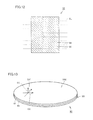
- silicon carbide single crystals 70a to 70i each having a main surface M70 are prepared.
- Silicon carbide single crystal 70 has hexagonal crystal structure and preferably has polytype of 4H.
- Plane direction of main surface M70 corresponds to plane direction of main surface M80 ( Fig. 1 ).
- Thickness (dimension in the lengthwise direction in the figure) of silicon carbide single crystal 70 is, for example, 0.5 mm to 10 mm.
- Planar shape of silicon carbide single crystal 70 is, for example, circular, of which diameter is preferably 25mm or larger and, more preferably, 100 mm or larger.
- a seed crystal 70S one having the characteristic value smaller than a prescribed value is selected as a seed crystal 70S.
- the prescribed value is, for example, the criterion of main surface M80, that is, 1 ⁇ 10 4 /cm 2 .
- backside (opposite to main surface M70) of seed crystal 70S is processed to increase surface roughness.
- This process is done by polishing the backside surface using abrasive particles having sufficiently large particle diameter.
- Particle size distribution of abrasive particles preferably has a component of 16 ⁇ m or larger.
- Average particle size of abrasive particles is preferably 5 ⁇ m to 50 ⁇ m, and more preferably 10 ⁇ m to 30 ⁇ m, and further preferably 12 to 25 ⁇ m.
- the abrasive particles are diamond particles. Further, preferably, the abrasive particles are used dispersed in slurry. Therefore, the polishing mentioned above is preferably conducted using diamond slurry. Generally, diamond slurry containing diamond particles having average particle size of 5 ⁇ m to 50 ⁇ m and having component of 16 ⁇ m in particle distribution is readily available.
- a backside surface having sufficient surface roughness may be formed from the outset, and the backside surface may be used without polishing.
- backside surface of seed crystal 70S formed by slicing with wire saw may be used without polishing.
- the backside surface as-sliced surface formed by slicing and not subjected to subsequent polishing may be used.
- the abrasive particles mentioned above are used.
- a coating film 21 including carbon is formed on the backside surface of seed crystal 70S.
- surface roughness of coating film 21 is made smaller than the surface roughness of backside surface of seed crystal 70S on which coating film 21 is formed.
- the coating film is formed by applying liquid material and, more preferably, the liquid material does not contain any solid matter. Therefore, thin coating film 21 can be formed easily and uniformly.
- coating film 21 is an organic film.
- the organic film is preferably formed of an organic resin.
- acrylic resin, phenol resin, urea resin or epoxy resin may be used, or resin having composition of photosensitive resin that is cross-linked or decomposed by light may be used.
- the photosensitive resin a positive or negative photoresist used for manufacturing semiconductor devices may be used.
- application technique of spin-coating has been established and, therefore, thickness of coating film 21 can be regulated easily. Exemplary manner of spin-coating is as follows.
- seed crystal 70S is held by suction on a holder.
- the holder is rotated at a prescribed speed of rotation, so that seed crystal 70S is also rotated.
- a photoresist is dropped on rotating seed crystal 70S and rotation is continued for a prescribed time period, so that the photoresist is applied thin and uniform.
- the speed of rotation is set, for example, to 1000 to 10000 rpm, time of rotation is set to 10 to 100 seconds and the coating thickness is at least 0.1 ⁇ m.
- the temperature and time for drying may appropriately be selected in accordance with the material and coating thickness of photoresist.
- the drying temperature is at least 100°C and at most 400°C, and the drying time is at least 5 minutes and at most 60 minutes. If the drying temperature is 120°C, the time necessary for volatilization is 15 minutes for the thickness of 5 ⁇ m, 8 minutes for the thickness of 2 ⁇ m and 3 minutes for the thickness of 1 ⁇ m.
- coating film 21 can be formed by once performing the process including the application and drying steps described above, thicker coating film 21 may be formed by repeating the process steps. If the number of repetition is too large, time for this process would be undesirably long and, therefore, typically the repetition of twice or three times is preferred.
- a base 41 having a mounting surface, on which seed crystal 70S is mounted is prepared.
- the mounting surface preferably includes a surface formed of carbon.
- base 41 is formed of graphite.
- the mounting surface is polished to improve flatness of the mounting surface.
- coating film 21 and base 41 are brought into contact with each other with adhesive 31 interposed.
- the contact is attained at a temperature of at least 50°C and at most 120°C under pressure of at least 0.01 Pa and at most 1 MPa to press the film and base to each other.
- adhesive 31 is applied not to run off the edge of the region sandwiched between seed crystal 70S and base 41, so as to prevent undesirable effect of adhesive 31 in the subsequent step of growing single crystal as will be described later.
- adhesive 31 contains resin that is carbonized to non-graphitizable carbon when heated, heat-resistant fine particles and a solvent and, more preferably, additionally contains carbohydrate.
- the resin that turns to non-graphitizable carbon is, for example, novolak resin, phenol resin, or furfuryl alcohol resin.
- the heat-resistant fine particles has a function, in a fixing layer formed by high-temperature heating of adhesive 31, of increasing filling rate of the fixing layer by uniformly distributing the non-graphitizable carbon mentioned above.
- heat-resistant material such as carbon (C) including graphite, silicon carbide (SiC), boron nitride (BN), or aluminum nitride (AlN) may be used.
- C carbon
- SiC silicon carbide
- BN boron nitride
- AlN aluminum nitride
- high-melting point metal or a compound such as a carbide or nitride of such metal may be used as the material.
- high-melting point metal may include tungsten (W), tantalum (Ta), molybdenum (Mo), titanium (Ti), zirconium (Zr) and hafnium (Hf).
- the heat-resistant fine particles have the particle size of, for example, 0.1 to 10 ⁇ m.
- sugar or its derivative may be used.
- the sugar may be monosaccharide such as glucose or polysaccharide such as cellulose.
- any solvent that can solve/disperse the resin and carbohydrate described above may appropriately be selected.
- the solvent is not limited to one composed of a single type of liquid, and it may be a mixture of a plurality of different liquids.
- a solvent containing alcohol for solving carbohydrate and celosolve acetate for solving resin may be used.
- the ratio of resin, carbohydrate, heat-resistant fine particles and solvent in adhesive 31 is appropriately selected to attain proper adhesion of seed crystal 70S and fixing strength.
- adhesive 31 may contain a component other than those mentioned above and, by way of example, it may contain additives such as a surface-active agent and a stabilizer.
- the amount of application of adhesive 31 is, preferably, at least 10 mg/cm 2 to at most 100 mg/cm 2 .
- the thickness of adhesive 31 is, preferably, at most 100 ⁇ m and more preferably, at most 50 ⁇ m.
- pre-baking of adhesive 31 takes place.
- Preferable temperature of pre-baking is at least 150°C.
- coating film 21 and adhesive 31 are heated.
- coating film 21 is carbonized and turns to carbon film 22.
- a carbon film 22 forms on seed crystal 70S.
- adhesive 31 is cured between carbon film 22 and base 41 and forms a fixing layer 32.
- seed crystal 70S is fixed on base 41.
- the heating mentioned above is done at a temperature of at least 800°C and at most 1800°C, for at least one hour and at most 10 hours, with a pressure of at least 0.13kPa and at most the atmospheric pressure, in an inert gas atmosphere.
- an inert gas atmosphere such as helium, argon or nitrogen gas is used as the inert gas.
- coating film 21 is carbonized. Coating film 21 may be carbonized before forming adhesive 31.
- a raw material 51 is placed in a crucible 42.
- Raw material 51 is, for example, silicon carbide powder.
- Crucible 42 is formed, for example, of graphite.
- base 41 is mounted such that seed crystal 70S is positioned facing the inside of crucible 42. As shown in Fig. 11 , base 41 may function as a lid of crucible 42.
- raw material 51 is sublimated and re-crystallized on seed crystal 70S as represented by arrows in the figure, and the sublimate deposits on seed crystal 70S.
- an ingot 52 is formed on seed crystal 70S.
- the temperature for sublimating and re-crystallizing silicon carbide is set, for example, to at least 2100°C and at most 2500°C. Further, temperature gradient is provided in crucible 42 such that the temperature of seed crystal 70S is lower than the temperature of raw material 51.
- Pressure in crucible 42 is preferably set to at least 1.3 kPa and at most the atmospheric pressure and, more preferably, at most 13 kPa to increase growth rate.
- ingot 52 is sliced.
- single crystal substrate 80 ( Fig. 1 ) is obtained.
- photoluminescence characteristics of main surface 80M of single crystal substrate 80 have the characteristic value described above.
- a semiconductor device that should desirably have small reverse leakage current such as a Schottky diode or an MOSFET (Metal Oxide Semiconductor Field Effect Transistor) as will be described later using single crystal substrate 80, the reverse leakage current can be made smaller.
- Growth conditions such as temperature, pressure and temperature gradient when ingot 52 is grown are optimized in accordance with facilities used in the actual mass-production process. If the optimization is inappropriate, the photoluminescence characteristics may fail to have the desired characteristic value. In that case, the growth conditions can be adjusted to attain the desired characteristic value.
- the maximum dimension of single crystal substrate 80 is preferably at least 75 mm and more preferably, at least 100 mm.
- single crystal substrate 80 is a circular wafer having the diameter of at least 100 mm. Using such a large wafer, semiconductor devices having small reverse leakage current can be manufactured with high efficiency.
- the silicon carbide substrate in accordance with the present embodiment is an epitaxial substrate 90 (silicon carbide substrate) having a silicon carbide layer 81 with a main surface M90 and a single crystal substrate 80 (base substrate) supporting silicon carbide layer 81. Silicon carbide layer 81 is epitaxially formed on single crystal substrate 80.
- Main surface M90 of epitaxial substrate 90 has specific photoluminescence characteristics as described later. A method of measuring photoluminescence characteristics will be described in the following.
- epitaxial substrate 90 is mounted on a photoluminescence measuring apparatus 400.
- Main surface M90 of epitaxial substrate 90 is irradiated with excitation light LE. Consequently, emission of photoluminescent light LL occurs on main surface M90.
- Transmitted light LH which is photoluminescent light LL passed through filter 434, is observed as an image by camera 435.
- main surface M90 emitting regions emitting photoluminescent light LL having a wavelength longer than 650 nm are observed. Which range of the wavelength exceeding 650 nm is observed is determined by characteristics of filter 434.
- maximum dimensions LX and LY along the directions DX and DY, respectively, are calculated for each emitting region RL.
- the number of those having the dimension LX not larger than a value obtained by dividing penetration length of excitation light LE to the hexagonal crystal silicon carbide by a tangent of off angle OA and having the dimension LY not larger than 15 ⁇ m is counted. Then, the obtained number is divided by the area (cm 2 ) of a portion as an object of observation of main surface M90.
- the resulting value is a characteristic value that serves as an index of photoluminescence characteristics of main surface M90 of epitaxial substrate 90.
- the main surface M90 of epitaxial substrate 90 in accordance with the present embodiment has this characteristic value of 1 ⁇ 10 4 /cm 2 or smaller.
- main surface M90 still has the value of 1 ⁇ 10 4 per 1 cm 2 or smaller, as the characteristic value.
- a single crystal substrate 80 having polytype 4H crystal structure was prepared.
- Main surface M80 of single crystal substrate 80 has an off angle OA ( Fig. 2 ) of 8 degrees from (0001) plane.
- Silicon carbide layer 81 of 10 ⁇ m in thickness was formed on main surface M80.
- Photoluminescence of main surface M90 of silicon carbide laver 81 was measured ( Fig. 14 ).
- Light emitted from a mercury lamp and passed through band-pass type filter 423 particularly passing light having the wavelength of about 313 nm was used as excitation light LE for measurement.
- Images of photoluminescent light LL caused by excitation light LE were picked up through filter 434 that particularly passes light having a wavelength of 750 nm or longer (a filter particularly prevents passage of light having cutoff wavelength shorter than 750 nm), whereby emitting regions RL were observed ( Fig. 16 ).
- Typical dimension of emitting regions RL was about 50 ⁇ m in the off direction DX and at most 15 ⁇ m and about 10 ⁇ m in average in direction DY perpendicular to off direction DX.
- Easiness of observing emitting regions RL depends on the characteristics of filter 434, and without filter 434, accurate observation of emitting regions RL was impossible.
- the dimension of emitting regions RL hardly changed in direction DY while the dimension becomes smaller as the incident angle becomes larger in direction DX.
- the dimension in direction DX was in proportion to inverse tangent of the incident angle.
- spectrum of photoluminescent light LL from emitting region RL of main surface M90 and the spectrum of photoluminescent light LL from other regions on main surface M90 were compared, in the range of wavelength from 650 nm to 950 nm ( Fig. 17 ).
- the spectrum of emitting region RL had higher intensity in a specific wavelength range than the spectrum of other regions BG. The difference in intensity is considered to be the reason why emitting region RL is brighter than the surrounding regions.
- the wavelength range was between 650 nm and 950 nm. Further, intensity was higher in a lower wavelength range.
- photoluminescence characteristic of main surface M90 of epitaxial substrate 90 has the above-described characteristic value.
- a semiconductor device that should desirably have small reverse leakage current such as a Schottky diode or an MOSFET (Metal Oxide Semiconductor Field Effect Transistor) as will be described later using epitaxial substrate 90, the reverse leakage current can be made smaller.
- main surface M90 of silicon carbide layer 81 has the desired photoluminescence characteristic, and photoluminescence characteristic of main surface M80 of single crystal substrate 80 may not necessarily satisfy the criterion described in Embodiment 1. If main surface M80 of single crystal substrate 80 satisfies the criterion described in Embodiment 1, however, desired photoluminescence characteristic can be imparted more reliably on the main surface M90 of silicon carbide layer 81.
- a semiconductor device in accordance with the present embodiment is a Schottky diode 500 (semiconductor device) having epitaxial substrate 90.
- Schottky diode 500 has epitaxial substrate 90, an anode electrode 225 and a cathode electrode 226.
- Anode electrode 225 is provided on a main surface on the side of silicon carbide layer 81 of epitaxial substrate 90.
- the cathode electrode is provided on a surface on the side of single crystal substrate 80 of epitaxial substrate 90.
- Single crystal substrate 80 has n + conductivity type, and silicon carbide layer 81 has n' conductivity type. Thickness of single crystal substrate 80 is, for example, at least 300 ⁇ m and at most 400 ⁇ m. By way of example, single crystal substrate 80 contains nitrogen atoms as an impurity, of which concentration is about 1 ⁇ 10 19 cm -3 . The thickness of silicon carbide layer 81 is, for example, 10 ⁇ m. By way of example, silicon carbide layer 81 contains nitrogen atoms as an impurity, of which concentration is about 5 ⁇ 10 15 cm -3 .
- Anode electrode 225 is formed of metal material that can establish Schottky contact with silicon carbide layer 81 where no voltage is applied to the electrode.
- Cathode electrode 226 is formed of metal material that can establish ohmic contact with single crystal substrate 80.
- Schottky diode 500 Operation of Schottky diode 500 will be described. At a contact portion between anode electrode 225 and silicon carbide layer 81. a Schottky barrier is formed. Therefore, if no voltage is applied or a negative voltage is applied to anode electrode 225, even if a potential difference is created between anode electrode 225 and cathode electrode 226, it is difficult to cause a current flow between these electrodes, since depletion layer extends in silicon carbide layer 81 because of the Schottky barrier.
- each of the single crystal substrates 80 has the photoluminescence characteristics described with reference to Embodiment 1.
- silicon carbide layer 81 is formed, whereby epitaxial substrates 90a to 90i having similar structure as epitaxial substrate 90 ( Fig. 13 ) are formed.
- photoluminescence of main surface M90 of each of epitaxial substrates 90a to 90i is measured.
- the process of measuring photoluminescence is the same as that of Embodiment 2 ( Fig. 14 ). Consequently, whether or not there is any defective region in which the number of emitting regions per unit area is larger than a prescribed number on main surface M90 is determined.
- the criterion for the number of emitting regions is the same as that described with reference to Embodiment 2.
- those having a defective region are found to be defective substrates 90N, and those not having any defective region are found to be non-defective substrates 90K.
- Defective substrates 90N are removed from the manufacturing process of Schottky diode 500. Consequently, from the set of main surfaces M90 of epitaxial substrates 90a to 90i, that is, from the fabrication regions for fabricating Schottky diodes 500, defective regions are removed.
- a plurality of anode electrodes 225 are formed on silicon carbide layer 81 of each of non-defective substrate 90K.
- a cathode electrode 226 is formed on single crystal substrate 80 (not shown in Fig. 21 ) of each of non-defective substrate 90.
- non-defective substrate 90K is diced along dotted lines LD in the figure, and a plurality of Schottky diodes 500 are obtained.
- epitaxial substrate 90 is formed in the similar manner as the method described above ( Fig. 19 ).
- anode electrode 225 is formed on each of regions R1 to R9. Further, cathode electrode 226 is formed on single crystal substrate 80 (not shown in Fig. 23 ) of epitaxial substrate 90. Epitaxial substrate 90 is diced along dotted lines LD in the figure. Though anode electrode 225 is formed unconditionally on each of regions R1 to R9 in the present embodiment, anode electrode 225 may not be formed on any of regions R1 to R9 that has a defective region.
- chips C1 to C9 are formed from regions R1 to R9 ( Figs. 22 and 23 ), respectively.
- any chip including a defective region is removed from resulting chips C1 to C9.
- the regions R1 to R9 of epitaxial substrate 90 possibly having a defective region or defective regions, those having any defective region are removed from the manufacturing process of Schottky diode 500. Consequently, defective regions are removed from the fabrication region for fabricating Schottky diodes 500.
- regions other than the defective region that is, regions not having any defective region among regions R1 to R9 are determined to be the fabrication regions.
- Schottky diodes 500 are formed from regions not having any defective region, of epitaxial substrate 90.
- reverse leakage current in Schottky diode 500 can be reduced.
- MOSFET 100 includes an epitaxial substrate 90V, an oxide film 126, a source electrode 111, an upper source electrode 127, a gate electrode 110 and a drain electrode 112.
- Epitaxial substrate 90V has single crystal substrate 80, a buffer layer 121, a breakdown voltage holding layer 122, a p region 123, an n + region 124 and a p + region 125.
- Single crystal substrate 80 and buffer layer 121 have n type conductivity.
- Impurity concentration of n type conductivity in buffer layer 121 is, for example, 5 ⁇ 10 17 cm -3 .
- Thickness of buffer layer 121 is, for example, 0.5 ⁇ m.
- Breakdown voltage holding layer 122 is formed of silicon carbide having n type conductivity, on buffer layer 121.
- breakdown voltage holding layer 122 has a thickness of 10 ⁇ m and concentration of n conductivity type impurity is 5 ⁇ 10 15 cm -3 .
- a plurality of p regions 123 having p type conductivity are formed spaced apart from each other.
- an n + region 124 is formed at a surface layer of p region 123.
- p + region 125 is formed on breakdown voltage holding layer 122 exposed between the plurality of p regions 123.
- oxide film 126 is formed on breakdown voltage holding layer 122 exposed between the plurality of p regions 123. Specifically, extending from above n + region 124 on one p region 123, over p region 123. breakdown voltage holding layer 122 exposed between two p-regions 123.
- oxide film 126 is formed on oxide film 126.
- gate electrode 110 is formed on oxide film 126.
- source electrode 111 is formed on n + region 124 and p + region 125.
- source electrode 111 is formed on source electrode 111.
- an upper source electrode 127 is formed on source electrode 111.
- the highest concentration of nitrogen atoms is at least 1 ⁇ 10 21 cm -3 . Therefore, mobility particularly at the channel region below oxide film 126 (the portion of p region 123 in contact with oxide film 126 between n + region 124 and breakdown voltage holding layer 122) can be improved.
- buffer layer 121 is formed of silicon carbide having n type conductivity, and its thickness is about 0.5 ⁇ m.
- impurity concentration in buffer layer 121 is, for example, 5 ⁇ 10 17 cm -3 .
- Thickness of breakdown voltage holding layer 122 is, for example, 10 ⁇ m.
- concentration of n type conductive impurity is, for example, 5 ⁇ 10 15 cm -3 .
- photoluminescence of the main surface (upper surface in Fig. 27 ) of epitaxial substrate 90V is measured substantially in the same manner as in Embodiment 3 ( Fig. 26 : step S120). If a defective region or regions are removed by the unit of substrate as in Embodiment 3, any defective epitaxial substrate is removed at this stage from the manufacturing process of MOSFET 100. On the other hand, if a defective region or regions are removed as parts of one substrate as in the modification 3 of Embodiment 3, removal from the manufacturing process of epitaxial substrate does not take place here, but the defective regions are removed after the dicing step described later.
- p region 123. n + region 124 and p + region 125 are formed in the following manner.
- p-type impurity is selectively introduced to a part of breakdown voltage holding layer 122, so that p region 123 is formed.
- n-type conductive impurity is selectively introduced to a prescribed region to form n + region 124
- p-type conductive impurity is selectively introduced to a prescribed region to form p + region 125.
- Selective introduction of impurities is done using a mask formed, for example, of an oxide film.
- an activation annealing treatment is done.
- annealing is done in an argon atmosphere, at a heating temperature of 1700°C for 30 minutes.
- the gate insulating film forming step ( Fig. 26 : step S140) is performed. Specifically, oxide film 126 is formed to cover breakdown voltage holding layer 122, p region 123, n + region 124 and p + region 125.
- the film may be formed by dry oxidation (thermal oxidation). Conditions for dry oxidation are, for example, heating temperature of 1200°C and heating time of 30 minutes.
- the nitrogen annealing step ( Fig. 26 : step S150) is done. Specifically, annealing is done in a nitrogen monoxide (NO) atmosphere. Conditions for this process are, for example, heating temperature of 1100°C and heating time of 120 minutes. As a result, nitrogen atoms are introduced to the vicinity of interface between oxide film 126 and each of breakdown voltage holding layer 122, p region 123, n + region 124 and p + region 125.
- NO nitrogen monoxide
- annealing using nitrogen monoxide annealing using nitrogen monoxide
- annealing using argon (Ar) gas as an inert gas may be performed.
- Conditions for the process are, for example, heating temperature of 1100°C and heating time of 60 minutes.
- source electrode 111 and drain electrode 112 are formed in the following manner.
- oxide film 126 using photolithography, a resist film having a pattern is formed. Using the resist film as a mask, portions of oxide film 126 positioned on n + region 124 and p + region 125 are removed by etching. Thus, openings are formed in oxide film 126. Next, a conductive film is formed to be in contact with each of n + region 124 and p + region 125 in the openings. Then, the resist film is removed, whereby portions of the conductive film that have been positioned on the resist film are removed (lift off).
- the conductive film may be a metal film and, by way of example, it is formed of nickel (Ni). As a result of this lift off, source electrode 111 is formed.
- heat treatment for alloying is preferably carried out.
- heat treatment is done in an atmosphere of argon (Ar) gas as an inert gas, at a heating temperature of 950°C for 2 minutes.
- source electrode 111 on source electrode 111, upper source electrode 127 is formed. Further, on oxide film 126, gate electrode 110 is formed. Further, on the backside surface (lower surface in the figure) of single crystal substrate 80, drain electrode 112 is formed.
- the dicing step ( Fig. 26 : step S170) is executed substantially in the similar manner as the dicing along dotted lines LD in Embodiment 3 ( Fig. 23 ).
- a plurality of chips are cut out. If the defective regions in one substrate are removed as in the modification of Embodiment 3, chips including defective regions are removed from the plurality of chips.
- MOSFET 100 ( Fig. 25 ) is obtained.
- a structure having conductivity types reversed from the structure described above, that is, p-type and n-type reversed, may be used.
- a vertical DiMOSFET has been described as an example, other semiconductor devices may be manufactured using the composite substrate in accordance with the present invention.
- a RESURF-JFET Reduced Surface Field-Junction Field Effect Transistor
- RESURF-JFET Reduced Surface Field-Junction Field Effect Transistor
Landscapes
- Chemical & Material Sciences (AREA)
- Engineering & Computer Science (AREA)
- Crystallography & Structural Chemistry (AREA)
- Materials Engineering (AREA)
- Metallurgy (AREA)
- Organic Chemistry (AREA)
- Inorganic Chemistry (AREA)
- Crystals, And After-Treatments Of Crystals (AREA)
- Investigating, Analyzing Materials By Fluorescence Or Luminescence (AREA)
- Testing Or Measuring Of Semiconductors Or The Like (AREA)
Priority Applications (1)
| Application Number | Priority Date | Filing Date | Title |
|---|---|---|---|
| EP20199216.1A EP3780114A1 (de) | 2010-12-27 | 2011-10-12 | Siliciumcarbidsubstrat, halbleiterbauelement, verfahren zur herstellung eines siliciumkarbidsubstrats und verfahren zur herstellung eines halbleiterbauelements |
Applications Claiming Priority (2)
| Application Number | Priority Date | Filing Date | Title |
|---|---|---|---|
| JP2010289593 | 2010-12-27 | ||
| PCT/JP2011/073407 WO2012090572A1 (ja) | 2010-12-27 | 2011-10-12 | 炭化珪素基板、半導体装置、炭化珪素基板の製造方法、および半導体装置の製造方法 |
Related Child Applications (2)
| Application Number | Title | Priority Date | Filing Date |
|---|---|---|---|
| EP20199216.1A Division EP3780114A1 (de) | 2010-12-27 | 2011-10-12 | Siliciumcarbidsubstrat, halbleiterbauelement, verfahren zur herstellung eines siliciumkarbidsubstrats und verfahren zur herstellung eines halbleiterbauelements |
| EP20199216.1A Division-Into EP3780114A1 (de) | 2010-12-27 | 2011-10-12 | Siliciumcarbidsubstrat, halbleiterbauelement, verfahren zur herstellung eines siliciumkarbidsubstrats und verfahren zur herstellung eines halbleiterbauelements |
Publications (3)
| Publication Number | Publication Date |
|---|---|
| EP2660366A1 true EP2660366A1 (de) | 2013-11-06 |
| EP2660366A4 EP2660366A4 (de) | 2014-07-23 |
| EP2660366B1 EP2660366B1 (de) | 2020-12-02 |
Family
ID=46315563
Family Applications (2)
| Application Number | Title | Priority Date | Filing Date |
|---|---|---|---|
| EP20199216.1A Pending EP3780114A1 (de) | 2010-12-27 | 2011-10-12 | Siliciumcarbidsubstrat, halbleiterbauelement, verfahren zur herstellung eines siliciumkarbidsubstrats und verfahren zur herstellung eines halbleiterbauelements |
| EP11847883.3A Active EP2660366B1 (de) | 2010-12-27 | 2011-10-12 | Verfahren zur herstellung eines siliciumcarbidsubstrats und verfahren zur herstellung eines halbleiterbauelements |
Family Applications Before (1)
| Application Number | Title | Priority Date | Filing Date |
|---|---|---|---|
| EP20199216.1A Pending EP3780114A1 (de) | 2010-12-27 | 2011-10-12 | Siliciumcarbidsubstrat, halbleiterbauelement, verfahren zur herstellung eines siliciumkarbidsubstrats und verfahren zur herstellung eines halbleiterbauelements |
Country Status (8)
| Country | Link |
|---|---|
| US (1) | US8624266B2 (de) |
| EP (2) | EP3780114A1 (de) |
| JP (4) | JP5857959B2 (de) |
| KR (1) | KR20120101055A (de) |
| CN (1) | CN102686787B (de) |
| CA (1) | CA2779961A1 (de) |
| TW (1) | TW201227955A (de) |
| WO (1) | WO2012090572A1 (de) |
Families Citing this family (13)
| Publication number | Priority date | Publication date | Assignee | Title |
|---|---|---|---|---|
| WO2012090572A1 (ja) * | 2010-12-27 | 2012-07-05 | 住友電気工業株式会社 | 炭化珪素基板、半導体装置、炭化珪素基板の製造方法、および半導体装置の製造方法 |
| JP5692195B2 (ja) * | 2012-10-02 | 2015-04-01 | 株式会社デンソー | 炭化珪素単結晶、炭化珪素半導体基板およびその製造方法 |
| JP2015013762A (ja) * | 2013-07-03 | 2015-01-22 | 住友電気工業株式会社 | 炭化珪素単結晶の製造方法および炭化珪素単結晶基板 |
| JP6444207B2 (ja) * | 2015-02-17 | 2018-12-26 | 株式会社ディスコ | 六方晶単結晶基板の検査方法及び検査装置 |
| JP6641814B2 (ja) * | 2015-09-11 | 2020-02-05 | 住友電気工業株式会社 | 炭化珪素エピタキシャル基板および炭化珪素半導体装置の製造方法 |
| JP6931995B2 (ja) | 2016-12-28 | 2021-09-08 | 昭和電工株式会社 | SiCウェハの欠陥測定方法、標準サンプル及びSiCエピタキシャルウェハの製造方法 |
| JP6986944B2 (ja) * | 2017-12-06 | 2021-12-22 | 昭和電工株式会社 | SiCエピタキシャルウェハの評価方法及び製造方法 |
| JP7447392B2 (ja) * | 2018-09-10 | 2024-03-12 | 株式会社レゾナック | SiC基板の評価方法及びSiCエピタキシャルウェハの製造方法 |
| JP7158965B2 (ja) * | 2018-09-14 | 2022-10-24 | キオクシア株式会社 | メモリシステム |
| TWI860350B (zh) * | 2019-04-26 | 2024-11-01 | 學校法人關西學院 | 碳化矽半導體基板、碳化矽半導體基板的製造方法、碳化矽半導體基板的製造裝置以及磊晶成長方法 |
| KR102268424B1 (ko) * | 2019-10-22 | 2021-06-22 | 에스케이씨 주식회사 | 종자정 접착층, 이를 적용한 적층체의 제조방법 및 웨이퍼의 제조방법 |
| JP7438162B2 (ja) * | 2021-04-15 | 2024-02-26 | 三菱電機株式会社 | 炭化珪素半導体装置の検査方法および炭化珪素半導体装置の製造方法 |
| CN113463197A (zh) * | 2021-06-18 | 2021-10-01 | 广州爱思威科技股份有限公司 | 一种碳化硅晶体的制备方法、碳化硅晶片、碳化硅衬底及半导体器件 |
Family Cites Families (27)
| Publication number | Priority date | Publication date | Assignee | Title |
|---|---|---|---|---|
| DE69841449D1 (de) * | 1998-03-19 | 2010-03-04 | Hitachi Ltd | Sperrschicht-feldeffekttransistor aus silicumcarbid |
| JP3864870B2 (ja) * | 2001-09-19 | 2007-01-10 | 住友電気工業株式会社 | 単結晶窒化ガリウム基板およびその成長方法並びにその製造方法 |
| JP3801125B2 (ja) * | 2001-10-09 | 2006-07-26 | 住友電気工業株式会社 | 単結晶窒化ガリウム基板と単結晶窒化ガリウムの結晶成長方法および単結晶窒化ガリウム基板の製造方法 |
| DE10247017B4 (de) * | 2001-10-12 | 2009-06-10 | Denso Corp., Kariya-shi | SiC-Einkristall, Verfahren zur Herstellung eines SiC-Einkristalls, SiC-Wafer mit einem Epitaxiefilm und Verfahren zur Herstellung eines SiC-Wafers, der einen Epitaxiefilm aufweist |
| JP3750622B2 (ja) * | 2002-03-22 | 2006-03-01 | 株式会社デンソー | エピタキシャル膜付きSiCウエハ及びその製造方法並びにSiC電子デバイス |
| JP2005154247A (ja) * | 2003-10-27 | 2005-06-16 | Ngk Insulators Ltd | 単結晶炭化珪素の製造方法および単結晶炭化珪素 |
| US7230274B2 (en) * | 2004-03-01 | 2007-06-12 | Cree, Inc | Reduction of carrot defects in silicon carbide epitaxy |
| JP4694144B2 (ja) * | 2004-05-14 | 2011-06-08 | 住友電気工業株式会社 | SiC単結晶の成長方法およびそれにより成長したSiC単結晶 |
| US7314520B2 (en) | 2004-10-04 | 2008-01-01 | Cree, Inc. | Low 1c screw dislocation 3 inch silicon carbide wafer |
| US7314521B2 (en) | 2004-10-04 | 2008-01-01 | Cree, Inc. | Low micropipe 100 mm silicon carbide wafer |
| JP3917154B2 (ja) * | 2004-11-19 | 2007-05-23 | 独立行政法人 宇宙航空研究開発機構 | 半導体試料の欠陥評価方法及び装置 |
| JP2006321707A (ja) * | 2005-04-22 | 2006-11-30 | Bridgestone Corp | 炭化ケイ素単結晶ウェハ及びその製造方法 |
| JP4633549B2 (ja) * | 2005-06-15 | 2011-02-16 | 財団法人電力中央研究所 | フォトルミネッセンスマッピング測定装置 |
| JP4818754B2 (ja) * | 2006-03-01 | 2011-11-16 | 新日本製鐵株式会社 | 炭化珪素単結晶インゴットの製造方法 |
| JP5192661B2 (ja) * | 2006-05-29 | 2013-05-08 | 一般財団法人電力中央研究所 | 炭化珪素半導体素子の製造方法 |
| GB0611156D0 (en) * | 2006-06-07 | 2006-07-19 | Qinetiq Ltd | Optical inspection |
| JP2008235767A (ja) * | 2007-03-23 | 2008-10-02 | Univ Of Fukui | 半導体素子及びその製造方法 |
| JP4469396B2 (ja) * | 2008-01-15 | 2010-05-26 | 新日本製鐵株式会社 | 炭化珪素単結晶インゴット、これから得られる基板及びエピタキシャルウェハ |
| JP4987792B2 (ja) * | 2008-04-17 | 2012-07-25 | 新日本製鐵株式会社 | エピタキシャル炭化珪素単結晶基板の製造方法 |
| JP2010095397A (ja) * | 2008-10-15 | 2010-04-30 | Nippon Steel Corp | 炭化珪素単結晶及び炭化珪素単結晶ウェハ |
| WO2010055569A1 (ja) * | 2008-11-13 | 2010-05-20 | 株式会社エコトロン | Mosfetおよびその製造方法 |
| US8536582B2 (en) * | 2008-12-01 | 2013-09-17 | Cree, Inc. | Stable power devices on low-angle off-cut silicon carbide crystals |
| JP2010153464A (ja) * | 2008-12-24 | 2010-07-08 | Toyota Central R&D Labs Inc | 半導体装置およびその製造方法 |
| US8044408B2 (en) * | 2009-05-20 | 2011-10-25 | Nippon Steel Corporation | SiC single-crystal substrate and method of producing SiC single-crystal substrate |
| WO2010140564A1 (ja) * | 2009-06-01 | 2010-12-09 | 三菱化学株式会社 | 窒化物半導体結晶およびその製造方法 |
| JP5515991B2 (ja) * | 2010-04-06 | 2014-06-11 | 新日鐵住金株式会社 | 炭化珪素バルク単結晶基板の欠陥検査方法、及びこの方法を用いた炭化珪素バルク単結晶基板の欠陥検査システム |
| WO2012090572A1 (ja) * | 2010-12-27 | 2012-07-05 | 住友電気工業株式会社 | 炭化珪素基板、半導体装置、炭化珪素基板の製造方法、および半導体装置の製造方法 |
-
2011
- 2011-10-12 WO PCT/JP2011/073407 patent/WO2012090572A1/ja not_active Ceased
- 2011-10-12 EP EP20199216.1A patent/EP3780114A1/de active Pending
- 2011-10-12 CA CA2779961A patent/CA2779961A1/en not_active Abandoned
- 2011-10-12 JP JP2012520616A patent/JP5857959B2/ja active Active
- 2011-10-12 EP EP11847883.3A patent/EP2660366B1/de active Active
- 2011-10-12 KR KR1020127014684A patent/KR20120101055A/ko not_active Ceased
- 2011-10-12 CN CN201180005010.9A patent/CN102686787B/zh active Active
- 2011-10-18 TW TW100137762A patent/TW201227955A/zh unknown
- 2011-12-22 US US13/334,855 patent/US8624266B2/en active Active
-
2015
- 2015-11-30 JP JP2015233277A patent/JP6123875B2/ja active Active
-
2017
- 2017-04-04 JP JP2017074552A patent/JP2017124974A/ja active Pending
-
2019
- 2019-12-04 JP JP2019219770A patent/JP2020043365A/ja active Pending
Also Published As
| Publication number | Publication date |
|---|---|
| WO2012090572A1 (ja) | 2012-07-05 |
| US20120161155A1 (en) | 2012-06-28 |
| JP5857959B2 (ja) | 2016-02-10 |
| EP2660366A4 (de) | 2014-07-23 |
| CA2779961A1 (en) | 2012-06-27 |
| JP6123875B2 (ja) | 2017-05-10 |
| EP3780114A1 (de) | 2021-02-17 |
| JP2020043365A (ja) | 2020-03-19 |
| CN102686787B (zh) | 2017-12-15 |
| US8624266B2 (en) | 2014-01-07 |
| EP2660366B1 (de) | 2020-12-02 |
| JP2017124974A (ja) | 2017-07-20 |
| TW201227955A (en) | 2012-07-01 |
| KR20120101055A (ko) | 2012-09-12 |
| JP2016121059A (ja) | 2016-07-07 |
| JPWO2012090572A1 (ja) | 2014-06-05 |
| CN102686787A (zh) | 2012-09-19 |
Similar Documents
| Publication | Publication Date | Title |
|---|---|---|
| US8624266B2 (en) | Silicon carbide substrate, semiconductor device, method of manufacturing silicon carbide substrate and method of manufacturing semiconductor device | |
| US12302619B2 (en) | Silicon carbide components and methods for producing silicon carbide components | |
| CN108884593B (zh) | 多晶SiC基板及其制造方法 | |
| EP2551891B1 (de) | Halbleitervorrichtung und herstellungsverfahren dafür | |
| US8513676B2 (en) | Semiconductor device and method for manufacturing same | |
| CN109887853B (zh) | SiC外延晶片的评价方法及制造方法 | |
| JP2008535761A (ja) | 歪み、反り、及びttvが少ない75ミリメートル炭化珪素ウェハ | |
| JPWO2018142744A1 (ja) | 炭化珪素エピタキシャル基板および炭化珪素半導体装置の製造方法 | |
| US20110254017A1 (en) | Manufacturing method for crystal, crystal, and semiconductor device | |
| CN103946431B (zh) | 制造碳化硅半导体器件的方法 | |
| WO2018142668A1 (ja) | 炭化珪素エピタキシャル基板および炭化珪素半導体装置の製造方法 | |
| CN115003866B (zh) | 碳化硅外延衬底及碳化硅半导体器件的制造方法 | |
| US20210225646A1 (en) | Silicon carbide epitaxial substrate and method of manufacturing silicon carbide semiconductor device | |
| CN119545874A (zh) | SiC基板及SiC外延晶片 |
Legal Events
| Date | Code | Title | Description |
|---|---|---|---|
| PUAI | Public reference made under article 153(3) epc to a published international application that has entered the european phase |
Free format text: ORIGINAL CODE: 0009012 |
|
| 17P | Request for examination filed |
Effective date: 20120618 |
|
| AK | Designated contracting states |
Kind code of ref document: A1 Designated state(s): AL AT BE BG CH CY CZ DE DK EE ES FI FR GB GR HR HU IE IS IT LI LT LU LV MC MK MT NL NO PL PT RO RS SE SI SK SM TR |
|
| DAX | Request for extension of the european patent (deleted) | ||
| A4 | Supplementary search report drawn up and despatched |
Effective date: 20140624 |
|
| RIC1 | Information provided on ipc code assigned before grant |
Ipc: H01L 29/16 20060101ALI20140617BHEP Ipc: H01L 21/20 20060101ALI20140617BHEP Ipc: C30B 29/36 20060101AFI20140617BHEP Ipc: C03B 23/06 20060101ALI20140617BHEP |
|
| STAA | Information on the status of an ep patent application or granted ep patent |
Free format text: STATUS: EXAMINATION IS IN PROGRESS |
|
| 17Q | First examination report despatched |
Effective date: 20170627 |
|
| GRAP | Despatch of communication of intention to grant a patent |
Free format text: ORIGINAL CODE: EPIDOSNIGR1 |
|
| STAA | Information on the status of an ep patent application or granted ep patent |
Free format text: STATUS: GRANT OF PATENT IS INTENDED |
|
| INTG | Intention to grant announced |
Effective date: 20200709 |
|
| GRAS | Grant fee paid |
Free format text: ORIGINAL CODE: EPIDOSNIGR3 |
|
| GRAA | (expected) grant |
Free format text: ORIGINAL CODE: 0009210 |
|
| STAA | Information on the status of an ep patent application or granted ep patent |
Free format text: STATUS: THE PATENT HAS BEEN GRANTED |
|
| AK | Designated contracting states |
Kind code of ref document: B1 Designated state(s): AL AT BE BG CH CY CZ DE DK EE ES FI FR GB GR HR HU IE IS IT LI LT LU LV MC MK MT NL NO PL PT RO RS SE SI SK SM TR |
|
| REG | Reference to a national code |
Ref country code: GB Ref legal event code: FG4D |
|
| REG | Reference to a national code |
Ref country code: AT Ref legal event code: REF Ref document number: 1341044 Country of ref document: AT Kind code of ref document: T Effective date: 20201215 Ref country code: CH Ref legal event code: EP |
|
| REG | Reference to a national code |
Ref country code: DE Ref legal event code: R096 Ref document number: 602011069543 Country of ref document: DE |
|
| REG | Reference to a national code |
Ref country code: IE Ref legal event code: FG4D |
|
| PG25 | Lapsed in a contracting state [announced via postgrant information from national office to epo] |
Ref country code: NO Free format text: LAPSE BECAUSE OF FAILURE TO SUBMIT A TRANSLATION OF THE DESCRIPTION OR TO PAY THE FEE WITHIN THE PRESCRIBED TIME-LIMIT Effective date: 20210302 Ref country code: FI Free format text: LAPSE BECAUSE OF FAILURE TO SUBMIT A TRANSLATION OF THE DESCRIPTION OR TO PAY THE FEE WITHIN THE PRESCRIBED TIME-LIMIT Effective date: 20201202 Ref country code: RS Free format text: LAPSE BECAUSE OF FAILURE TO SUBMIT A TRANSLATION OF THE DESCRIPTION OR TO PAY THE FEE WITHIN THE PRESCRIBED TIME-LIMIT Effective date: 20201202 Ref country code: GR Free format text: LAPSE BECAUSE OF FAILURE TO SUBMIT A TRANSLATION OF THE DESCRIPTION OR TO PAY THE FEE WITHIN THE PRESCRIBED TIME-LIMIT Effective date: 20210303 |
|
| REG | Reference to a national code |
Ref country code: NL Ref legal event code: MP Effective date: 20201202 |
|
| REG | Reference to a national code |
Ref country code: AT Ref legal event code: MK05 Ref document number: 1341044 Country of ref document: AT Kind code of ref document: T Effective date: 20201202 |
|
| PG25 | Lapsed in a contracting state [announced via postgrant information from national office to epo] |
Ref country code: BG Free format text: LAPSE BECAUSE OF FAILURE TO SUBMIT A TRANSLATION OF THE DESCRIPTION OR TO PAY THE FEE WITHIN THE PRESCRIBED TIME-LIMIT Effective date: 20210302 Ref country code: PL Free format text: LAPSE BECAUSE OF FAILURE TO SUBMIT A TRANSLATION OF THE DESCRIPTION OR TO PAY THE FEE WITHIN THE PRESCRIBED TIME-LIMIT Effective date: 20201202 Ref country code: LV Free format text: LAPSE BECAUSE OF FAILURE TO SUBMIT A TRANSLATION OF THE DESCRIPTION OR TO PAY THE FEE WITHIN THE PRESCRIBED TIME-LIMIT Effective date: 20201202 Ref country code: SE Free format text: LAPSE BECAUSE OF FAILURE TO SUBMIT A TRANSLATION OF THE DESCRIPTION OR TO PAY THE FEE WITHIN THE PRESCRIBED TIME-LIMIT Effective date: 20201202 |
|
| PG25 | Lapsed in a contracting state [announced via postgrant information from national office to epo] |
Ref country code: HR Free format text: LAPSE BECAUSE OF FAILURE TO SUBMIT A TRANSLATION OF THE DESCRIPTION OR TO PAY THE FEE WITHIN THE PRESCRIBED TIME-LIMIT Effective date: 20201202 Ref country code: NL Free format text: LAPSE BECAUSE OF FAILURE TO SUBMIT A TRANSLATION OF THE DESCRIPTION OR TO PAY THE FEE WITHIN THE PRESCRIBED TIME-LIMIT Effective date: 20201202 |
|
| REG | Reference to a national code |
Ref country code: LT Ref legal event code: MG9D |
|
| PG25 | Lapsed in a contracting state [announced via postgrant information from national office to epo] |
Ref country code: RO Free format text: LAPSE BECAUSE OF FAILURE TO SUBMIT A TRANSLATION OF THE DESCRIPTION OR TO PAY THE FEE WITHIN THE PRESCRIBED TIME-LIMIT Effective date: 20201202 Ref country code: PT Free format text: LAPSE BECAUSE OF FAILURE TO SUBMIT A TRANSLATION OF THE DESCRIPTION OR TO PAY THE FEE WITHIN THE PRESCRIBED TIME-LIMIT Effective date: 20210405 Ref country code: SK Free format text: LAPSE BECAUSE OF FAILURE TO SUBMIT A TRANSLATION OF THE DESCRIPTION OR TO PAY THE FEE WITHIN THE PRESCRIBED TIME-LIMIT Effective date: 20201202 Ref country code: LT Free format text: LAPSE BECAUSE OF FAILURE TO SUBMIT A TRANSLATION OF THE DESCRIPTION OR TO PAY THE FEE WITHIN THE PRESCRIBED TIME-LIMIT Effective date: 20201202 Ref country code: CZ Free format text: LAPSE BECAUSE OF FAILURE TO SUBMIT A TRANSLATION OF THE DESCRIPTION OR TO PAY THE FEE WITHIN THE PRESCRIBED TIME-LIMIT Effective date: 20201202 Ref country code: EE Free format text: LAPSE BECAUSE OF FAILURE TO SUBMIT A TRANSLATION OF THE DESCRIPTION OR TO PAY THE FEE WITHIN THE PRESCRIBED TIME-LIMIT Effective date: 20201202 Ref country code: SM Free format text: LAPSE BECAUSE OF FAILURE TO SUBMIT A TRANSLATION OF THE DESCRIPTION OR TO PAY THE FEE WITHIN THE PRESCRIBED TIME-LIMIT Effective date: 20201202 |
|
| PG25 | Lapsed in a contracting state [announced via postgrant information from national office to epo] |
Ref country code: AT Free format text: LAPSE BECAUSE OF FAILURE TO SUBMIT A TRANSLATION OF THE DESCRIPTION OR TO PAY THE FEE WITHIN THE PRESCRIBED TIME-LIMIT Effective date: 20201202 |
|
| REG | Reference to a national code |
Ref country code: DE Ref legal event code: R097 Ref document number: 602011069543 Country of ref document: DE |
|
| PG25 | Lapsed in a contracting state [announced via postgrant information from national office to epo] |
Ref country code: IS Free format text: LAPSE BECAUSE OF FAILURE TO SUBMIT A TRANSLATION OF THE DESCRIPTION OR TO PAY THE FEE WITHIN THE PRESCRIBED TIME-LIMIT Effective date: 20210402 |
|
| PLBE | No opposition filed within time limit |
Free format text: ORIGINAL CODE: 0009261 |
|
| STAA | Information on the status of an ep patent application or granted ep patent |
Free format text: STATUS: NO OPPOSITION FILED WITHIN TIME LIMIT |
|
| PG25 | Lapsed in a contracting state [announced via postgrant information from national office to epo] |
Ref country code: AL Free format text: LAPSE BECAUSE OF FAILURE TO SUBMIT A TRANSLATION OF THE DESCRIPTION OR TO PAY THE FEE WITHIN THE PRESCRIBED TIME-LIMIT Effective date: 20201202 Ref country code: IT Free format text: LAPSE BECAUSE OF FAILURE TO SUBMIT A TRANSLATION OF THE DESCRIPTION OR TO PAY THE FEE WITHIN THE PRESCRIBED TIME-LIMIT Effective date: 20201202 |
|
| 26N | No opposition filed |
Effective date: 20210903 |
|
| PG25 | Lapsed in a contracting state [announced via postgrant information from national office to epo] |
Ref country code: DK Free format text: LAPSE BECAUSE OF FAILURE TO SUBMIT A TRANSLATION OF THE DESCRIPTION OR TO PAY THE FEE WITHIN THE PRESCRIBED TIME-LIMIT Effective date: 20201202 Ref country code: ES Free format text: LAPSE BECAUSE OF FAILURE TO SUBMIT A TRANSLATION OF THE DESCRIPTION OR TO PAY THE FEE WITHIN THE PRESCRIBED TIME-LIMIT Effective date: 20201202 Ref country code: SI Free format text: LAPSE BECAUSE OF FAILURE TO SUBMIT A TRANSLATION OF THE DESCRIPTION OR TO PAY THE FEE WITHIN THE PRESCRIBED TIME-LIMIT Effective date: 20201202 |
|
| REG | Reference to a national code |
Ref country code: CH Ref legal event code: PL |
|
| PG25 | Lapsed in a contracting state [announced via postgrant information from national office to epo] |
Ref country code: IS Free format text: LAPSE BECAUSE OF FAILURE TO SUBMIT A TRANSLATION OF THE DESCRIPTION OR TO PAY THE FEE WITHIN THE PRESCRIBED TIME-LIMIT Effective date: 20210402 |
|
| REG | Reference to a national code |
Ref country code: BE Ref legal event code: MM Effective date: 20211031 |
|
| GBPC | Gb: european patent ceased through non-payment of renewal fee |
Effective date: 20211012 |
|
| PG25 | Lapsed in a contracting state [announced via postgrant information from national office to epo] |
Ref country code: MC Free format text: LAPSE BECAUSE OF FAILURE TO SUBMIT A TRANSLATION OF THE DESCRIPTION OR TO PAY THE FEE WITHIN THE PRESCRIBED TIME-LIMIT Effective date: 20201202 |
|
| PG25 | Lapsed in a contracting state [announced via postgrant information from national office to epo] |
Ref country code: LU Free format text: LAPSE BECAUSE OF NON-PAYMENT OF DUE FEES Effective date: 20211012 Ref country code: GB Free format text: LAPSE BECAUSE OF NON-PAYMENT OF DUE FEES Effective date: 20211012 Ref country code: BE Free format text: LAPSE BECAUSE OF NON-PAYMENT OF DUE FEES Effective date: 20211031 |
|
| PG25 | Lapsed in a contracting state [announced via postgrant information from national office to epo] |
Ref country code: LI Free format text: LAPSE BECAUSE OF NON-PAYMENT OF DUE FEES Effective date: 20211031 Ref country code: CH Free format text: LAPSE BECAUSE OF NON-PAYMENT OF DUE FEES Effective date: 20211031 |
|
| PG25 | Lapsed in a contracting state [announced via postgrant information from national office to epo] |
Ref country code: FR Free format text: LAPSE BECAUSE OF NON-PAYMENT OF DUE FEES Effective date: 20211031 |
|
| PG25 | Lapsed in a contracting state [announced via postgrant information from national office to epo] |
Ref country code: IE Free format text: LAPSE BECAUSE OF NON-PAYMENT OF DUE FEES Effective date: 20211012 |
|
| PG25 | Lapsed in a contracting state [announced via postgrant information from national office to epo] |
Ref country code: HU Free format text: LAPSE BECAUSE OF FAILURE TO SUBMIT A TRANSLATION OF THE DESCRIPTION OR TO PAY THE FEE WITHIN THE PRESCRIBED TIME-LIMIT; INVALID AB INITIO Effective date: 20111012 Ref country code: CY Free format text: LAPSE BECAUSE OF FAILURE TO SUBMIT A TRANSLATION OF THE DESCRIPTION OR TO PAY THE FEE WITHIN THE PRESCRIBED TIME-LIMIT Effective date: 20201202 |
|
| P01 | Opt-out of the competence of the unified patent court (upc) registered |
Effective date: 20230515 |
|
| PG25 | Lapsed in a contracting state [announced via postgrant information from national office to epo] |
Ref country code: MK Free format text: LAPSE BECAUSE OF FAILURE TO SUBMIT A TRANSLATION OF THE DESCRIPTION OR TO PAY THE FEE WITHIN THE PRESCRIBED TIME-LIMIT Effective date: 20201202 |
|
| PG25 | Lapsed in a contracting state [announced via postgrant information from national office to epo] |
Ref country code: TR Free format text: LAPSE BECAUSE OF FAILURE TO SUBMIT A TRANSLATION OF THE DESCRIPTION OR TO PAY THE FEE WITHIN THE PRESCRIBED TIME-LIMIT Effective date: 20201202 |
|
| PG25 | Lapsed in a contracting state [announced via postgrant information from national office to epo] |
Ref country code: MT Free format text: LAPSE BECAUSE OF FAILURE TO SUBMIT A TRANSLATION OF THE DESCRIPTION OR TO PAY THE FEE WITHIN THE PRESCRIBED TIME-LIMIT Effective date: 20201202 |
|
| PGFP | Annual fee paid to national office [announced via postgrant information from national office to epo] |
Ref country code: DE Payment date: 20250902 Year of fee payment: 15 |