EP2660956A1 - Machine électrique tournante - Google Patents
Machine électrique tournante Download PDFInfo
- Publication number
- EP2660956A1 EP2660956A1 EP11854308.1A EP11854308A EP2660956A1 EP 2660956 A1 EP2660956 A1 EP 2660956A1 EP 11854308 A EP11854308 A EP 11854308A EP 2660956 A1 EP2660956 A1 EP 2660956A1
- Authority
- EP
- European Patent Office
- Prior art keywords
- peel
- rotating electrical
- segment conductor
- electrical machine
- bonding
- Prior art date
- Legal status (The legal status is an assumption and is not a legal conclusion. Google has not performed a legal analysis and makes no representation as to the accuracy of the status listed.)
- Withdrawn
Links
Images




Classifications
-
- H—ELECTRICITY
- H02—GENERATION; CONVERSION OR DISTRIBUTION OF ELECTRIC POWER
- H02K—DYNAMO-ELECTRIC MACHINES
- H02K3/00—Details of windings
- H02K3/04—Windings characterised by the conductor shape, form or construction, e.g. with bar conductors
- H02K3/12—Windings characterised by the conductor shape, form or construction, e.g. with bar conductors arranged in slots
-
- B—PERFORMING OPERATIONS; TRANSPORTING
- B60—VEHICLES IN GENERAL
- B60L—PROPULSION OF ELECTRICALLY-PROPELLED VEHICLES; SUPPLYING ELECTRIC POWER FOR AUXILIARY EQUIPMENT OF ELECTRICALLY-PROPELLED VEHICLES; ELECTRODYNAMIC BRAKE SYSTEMS FOR VEHICLES IN GENERAL; MAGNETIC SUSPENSION OR LEVITATION FOR VEHICLES; MONITORING OPERATING VARIABLES OF ELECTRICALLY-PROPELLED VEHICLES; ELECTRIC SAFETY DEVICES FOR ELECTRICALLY-PROPELLED VEHICLES
- B60L15/00—Methods, circuits, or devices for controlling the traction-motor speed of electrically-propelled vehicles
- B60L15/20—Methods, circuits, or devices for controlling the traction-motor speed of electrically-propelled vehicles for control of the vehicle or its driving motor to achieve a desired performance, e.g. speed, torque, programmed variation of speed
-
- B—PERFORMING OPERATIONS; TRANSPORTING
- B60—VEHICLES IN GENERAL
- B60L—PROPULSION OF ELECTRICALLY-PROPELLED VEHICLES; SUPPLYING ELECTRIC POWER FOR AUXILIARY EQUIPMENT OF ELECTRICALLY-PROPELLED VEHICLES; ELECTRODYNAMIC BRAKE SYSTEMS FOR VEHICLES IN GENERAL; MAGNETIC SUSPENSION OR LEVITATION FOR VEHICLES; MONITORING OPERATING VARIABLES OF ELECTRICALLY-PROPELLED VEHICLES; ELECTRIC SAFETY DEVICES FOR ELECTRICALLY-PROPELLED VEHICLES
- B60L3/00—Electric devices on electrically-propelled vehicles for safety purposes; Monitoring operating variables, e.g. speed, deceleration or energy consumption
- B60L3/0023—Detecting, eliminating, remedying or compensating for drive train abnormalities, e.g. failures within the drive train
- B60L3/0061—Detecting, eliminating, remedying or compensating for drive train abnormalities, e.g. failures within the drive train relating to electrical machines
-
- B—PERFORMING OPERATIONS; TRANSPORTING
- B60—VEHICLES IN GENERAL
- B60L—PROPULSION OF ELECTRICALLY-PROPELLED VEHICLES; SUPPLYING ELECTRIC POWER FOR AUXILIARY EQUIPMENT OF ELECTRICALLY-PROPELLED VEHICLES; ELECTRODYNAMIC BRAKE SYSTEMS FOR VEHICLES IN GENERAL; MAGNETIC SUSPENSION OR LEVITATION FOR VEHICLES; MONITORING OPERATING VARIABLES OF ELECTRICALLY-PROPELLED VEHICLES; ELECTRIC SAFETY DEVICES FOR ELECTRICALLY-PROPELLED VEHICLES
- B60L50/00—Electric propulsion with power supplied within the vehicle
- B60L50/10—Electric propulsion with power supplied within the vehicle using propulsion power supplied by engine-driven generators, e.g. generators driven by combustion engines
- B60L50/16—Electric propulsion with power supplied within the vehicle using propulsion power supplied by engine-driven generators, e.g. generators driven by combustion engines with provision for separate direct mechanical propulsion
-
- H—ELECTRICITY
- H02—GENERATION; CONVERSION OR DISTRIBUTION OF ELECTRIC POWER
- H02K—DYNAMO-ELECTRIC MACHINES
- H02K15/00—Processes or apparatus specially adapted for manufacturing, assembling, maintaining or repairing of dynamo-electric machines
- H02K15/10—Applying solid insulation to windings, stators or rotors, e.g. applying insulating tapes
- H02K15/105—Applying solid insulation to windings, stators or rotors, e.g. applying insulating tapes to the windings
-
- H—ELECTRICITY
- H02—GENERATION; CONVERSION OR DISTRIBUTION OF ELECTRIC POWER
- H02K—DYNAMO-ELECTRIC MACHINES
- H02K15/00—Processes or apparatus specially adapted for manufacturing, assembling, maintaining or repairing of dynamo-electric machines
- H02K15/30—Manufacture of winding connections
- H02K15/33—Connecting winding sections; Forming leads; Connecting leads to terminals
- H02K15/35—Form-wound windings
-
- H—ELECTRICITY
- H02—GENERATION; CONVERSION OR DISTRIBUTION OF ELECTRIC POWER
- H02K—DYNAMO-ELECTRIC MACHINES
- H02K3/00—Details of windings
- H02K3/32—Windings characterised by the shape, form or construction of the insulation
-
- B—PERFORMING OPERATIONS; TRANSPORTING
- B60—VEHICLES IN GENERAL
- B60L—PROPULSION OF ELECTRICALLY-PROPELLED VEHICLES; SUPPLYING ELECTRIC POWER FOR AUXILIARY EQUIPMENT OF ELECTRICALLY-PROPELLED VEHICLES; ELECTRODYNAMIC BRAKE SYSTEMS FOR VEHICLES IN GENERAL; MAGNETIC SUSPENSION OR LEVITATION FOR VEHICLES; MONITORING OPERATING VARIABLES OF ELECTRICALLY-PROPELLED VEHICLES; ELECTRIC SAFETY DEVICES FOR ELECTRICALLY-PROPELLED VEHICLES
- B60L2220/00—Electrical machine types; Structures or applications thereof
- B60L2220/50—Structural details of electrical machines
-
- B—PERFORMING OPERATIONS; TRANSPORTING
- B60—VEHICLES IN GENERAL
- B60L—PROPULSION OF ELECTRICALLY-PROPELLED VEHICLES; SUPPLYING ELECTRIC POWER FOR AUXILIARY EQUIPMENT OF ELECTRICALLY-PROPELLED VEHICLES; ELECTRODYNAMIC BRAKE SYSTEMS FOR VEHICLES IN GENERAL; MAGNETIC SUSPENSION OR LEVITATION FOR VEHICLES; MONITORING OPERATING VARIABLES OF ELECTRICALLY-PROPELLED VEHICLES; ELECTRIC SAFETY DEVICES FOR ELECTRICALLY-PROPELLED VEHICLES
- B60L2240/00—Control parameters of input or output; Target parameters
- B60L2240/10—Vehicle control parameters
- B60L2240/36—Temperature of vehicle components or parts
-
- B—PERFORMING OPERATIONS; TRANSPORTING
- B60—VEHICLES IN GENERAL
- B60L—PROPULSION OF ELECTRICALLY-PROPELLED VEHICLES; SUPPLYING ELECTRIC POWER FOR AUXILIARY EQUIPMENT OF ELECTRICALLY-PROPELLED VEHICLES; ELECTRODYNAMIC BRAKE SYSTEMS FOR VEHICLES IN GENERAL; MAGNETIC SUSPENSION OR LEVITATION FOR VEHICLES; MONITORING OPERATING VARIABLES OF ELECTRICALLY-PROPELLED VEHICLES; ELECTRIC SAFETY DEVICES FOR ELECTRICALLY-PROPELLED VEHICLES
- B60L2240/00—Control parameters of input or output; Target parameters
- B60L2240/40—Drive Train control parameters
- B60L2240/42—Drive Train control parameters related to electric machines
- B60L2240/421—Speed
-
- B—PERFORMING OPERATIONS; TRANSPORTING
- B60—VEHICLES IN GENERAL
- B60L—PROPULSION OF ELECTRICALLY-PROPELLED VEHICLES; SUPPLYING ELECTRIC POWER FOR AUXILIARY EQUIPMENT OF ELECTRICALLY-PROPELLED VEHICLES; ELECTRODYNAMIC BRAKE SYSTEMS FOR VEHICLES IN GENERAL; MAGNETIC SUSPENSION OR LEVITATION FOR VEHICLES; MONITORING OPERATING VARIABLES OF ELECTRICALLY-PROPELLED VEHICLES; ELECTRIC SAFETY DEVICES FOR ELECTRICALLY-PROPELLED VEHICLES
- B60L2240/00—Control parameters of input or output; Target parameters
- B60L2240/40—Drive Train control parameters
- B60L2240/42—Drive Train control parameters related to electric machines
- B60L2240/423—Torque
-
- B—PERFORMING OPERATIONS; TRANSPORTING
- B60—VEHICLES IN GENERAL
- B60L—PROPULSION OF ELECTRICALLY-PROPELLED VEHICLES; SUPPLYING ELECTRIC POWER FOR AUXILIARY EQUIPMENT OF ELECTRICALLY-PROPELLED VEHICLES; ELECTRODYNAMIC BRAKE SYSTEMS FOR VEHICLES IN GENERAL; MAGNETIC SUSPENSION OR LEVITATION FOR VEHICLES; MONITORING OPERATING VARIABLES OF ELECTRICALLY-PROPELLED VEHICLES; ELECTRIC SAFETY DEVICES FOR ELECTRICALLY-PROPELLED VEHICLES
- B60L2240/00—Control parameters of input or output; Target parameters
- B60L2240/40—Drive Train control parameters
- B60L2240/44—Drive Train control parameters related to combustion engines
- B60L2240/443—Torque
-
- Y—GENERAL TAGGING OF NEW TECHNOLOGICAL DEVELOPMENTS; GENERAL TAGGING OF CROSS-SECTIONAL TECHNOLOGIES SPANNING OVER SEVERAL SECTIONS OF THE IPC; TECHNICAL SUBJECTS COVERED BY FORMER USPC CROSS-REFERENCE ART COLLECTIONS [XRACs] AND DIGESTS
- Y02—TECHNOLOGIES OR APPLICATIONS FOR MITIGATION OR ADAPTATION AGAINST CLIMATE CHANGE
- Y02T—CLIMATE CHANGE MITIGATION TECHNOLOGIES RELATED TO TRANSPORTATION
- Y02T10/00—Road transport of goods or passengers
- Y02T10/60—Other road transportation technologies with climate change mitigation effect
- Y02T10/64—Electric machine technologies in electromobility
-
- Y—GENERAL TAGGING OF NEW TECHNOLOGICAL DEVELOPMENTS; GENERAL TAGGING OF CROSS-SECTIONAL TECHNOLOGIES SPANNING OVER SEVERAL SECTIONS OF THE IPC; TECHNICAL SUBJECTS COVERED BY FORMER USPC CROSS-REFERENCE ART COLLECTIONS [XRACs] AND DIGESTS
- Y02—TECHNOLOGIES OR APPLICATIONS FOR MITIGATION OR ADAPTATION AGAINST CLIMATE CHANGE
- Y02T—CLIMATE CHANGE MITIGATION TECHNOLOGIES RELATED TO TRANSPORTATION
- Y02T10/00—Road transport of goods or passengers
- Y02T10/60—Other road transportation technologies with climate change mitigation effect
- Y02T10/70—Energy storage systems for electromobility, e.g. batteries
-
- Y—GENERAL TAGGING OF NEW TECHNOLOGICAL DEVELOPMENTS; GENERAL TAGGING OF CROSS-SECTIONAL TECHNOLOGIES SPANNING OVER SEVERAL SECTIONS OF THE IPC; TECHNICAL SUBJECTS COVERED BY FORMER USPC CROSS-REFERENCE ART COLLECTIONS [XRACs] AND DIGESTS
- Y02—TECHNOLOGIES OR APPLICATIONS FOR MITIGATION OR ADAPTATION AGAINST CLIMATE CHANGE
- Y02T—CLIMATE CHANGE MITIGATION TECHNOLOGIES RELATED TO TRANSPORTATION
- Y02T10/00—Road transport of goods or passengers
- Y02T10/60—Other road transportation technologies with climate change mitigation effect
- Y02T10/7072—Electromobility specific charging systems or methods for batteries, ultracapacitors, supercapacitors or double-layer capacitors
-
- Y—GENERAL TAGGING OF NEW TECHNOLOGICAL DEVELOPMENTS; GENERAL TAGGING OF CROSS-SECTIONAL TECHNOLOGIES SPANNING OVER SEVERAL SECTIONS OF THE IPC; TECHNICAL SUBJECTS COVERED BY FORMER USPC CROSS-REFERENCE ART COLLECTIONS [XRACs] AND DIGESTS
- Y02—TECHNOLOGIES OR APPLICATIONS FOR MITIGATION OR ADAPTATION AGAINST CLIMATE CHANGE
- Y02T—CLIMATE CHANGE MITIGATION TECHNOLOGIES RELATED TO TRANSPORTATION
- Y02T10/00—Road transport of goods or passengers
- Y02T10/60—Other road transportation technologies with climate change mitigation effect
- Y02T10/72—Electric energy management in electromobility
-
- Y—GENERAL TAGGING OF NEW TECHNOLOGICAL DEVELOPMENTS; GENERAL TAGGING OF CROSS-SECTIONAL TECHNOLOGIES SPANNING OVER SEVERAL SECTIONS OF THE IPC; TECHNICAL SUBJECTS COVERED BY FORMER USPC CROSS-REFERENCE ART COLLECTIONS [XRACs] AND DIGESTS
- Y02—TECHNOLOGIES OR APPLICATIONS FOR MITIGATION OR ADAPTATION AGAINST CLIMATE CHANGE
- Y02T—CLIMATE CHANGE MITIGATION TECHNOLOGIES RELATED TO TRANSPORTATION
- Y02T90/00—Enabling technologies or technologies with a potential or indirect contribution to GHG emissions mitigation
- Y02T90/10—Technologies relating to charging of electric vehicles
- Y02T90/16—Information or communication technologies improving the operation of electric vehicles
Definitions
- the present invention relates to a rotating electrical machine, and more particularly, to a segment conductor of a stator of a rotating electrical machine.
- Rotating electrical machines used for driving vehicles have been required to have a decreased size and a high output.
- a rectangular wire has been used, and a winding system using a rectangular wire segment has been used.
- a segment conductor of a rectangular wire molded in the shape of U is inserted into a stator iron core, and a straight potion of the segment conductor, which protrudes from a stator iron core, is twisted in the circumferential direction, whereby segment conductors arranged in mutually-different slots are connected to each other.
- an insulator such as an enamel film is peeled off in advance, and the end portion is bonded to a segment conductor arranged in another slot through welding or the like.
- an object of the present invention is to improve the reliability of a rotating electrical machine by improving the stability of the bonding portion of the coil.
- a rotating electrical machine includes: a stator that includes a stator iron core having a plurality of slots and a stator winding configured by connecting a plurality of segment conductors each formed by a rectangular wire including an end portion and an insulating film; and a rotator that faces the stator through a gap, wherein the segment conductor includes a coated portion coated with the insulating film and a peel-off portion from which the insulating film is peeled off and has a cross-section smaller than the coated portion, the segment conductor and another segment conductor are bonded to each other outside the slots so as to bring at least parts of the peel-off portions as bonding faces into contact with each other, at least one segment conductor of two segment conductors that are bonded to each other includes a straight portion that is formed in a linear shape in an axial direction and an arc portion that is continuous to the straight portion and is formed in an arc shape in the end portion, and the peel-off portion as the bonding face is
- the segment conductor including the arc portion includes an inclined portion that is continuous to the arc portion and is formed to extend in a direction different from a direction of the straight portion, and the peel-off portion as the bonding face is configured by the straight portion, the arc portion and the inclined portion, or the straight portion, the arc portion and a part of the inclined portion on a side of the arc portion.
- the rotating electrical machine of the first or second aspect it is preferable that, in the segment conductor bonded to the segment conductor including the arc portion, the coated portion and the peel-off portion are formed in a linear shape in the axial direction in a welding-side coil end.
- the segment conductor including the inclined portion is a connecting wire and connects two segment conductors other than the segment conductor.
- a peel-off length of a face other than the bonding face is shorter than a peel-off length of the bonding face.
- the peel-off portions are disposed on the bonding faces on which the peel-off portions face each other and other faces parallel to the bonding faces.
- the reliability of a rotating electrical machine can be improved by improving the stability of bonding between segment conductors.
- an engine 120 As illustrated in FIG. 1 , in a hybrid vehicle 100, an engine 120, first and second rotating electrical machines 200 and 202, and a high-voltage battery 180 are mounted.
- the battery 180 is configured as a secondary battery such as a lithium ion battery or a nickel-metal hydride battery, and outputs high-voltage DC power of 250 volts to 600 volts or higher.
- the battery 180 supplies DC power to the rotating electrical machines 200 and 202.
- DC power is supplied from the rotating electrical machines 200 and 202 to the battery 180.
- the transmission/reception of DC power between the battery 180 and the rotating electrical machines 200 and 202 are performed through a power converting device 600.
- a battery that supplies low-voltage power (for example, 14 volts-based power) is mounted in the vehicle.
- the rotating torque according to the engine 120 and the rotating electrical machines 200 and 202 is delivered to front wheels 110 through a transmission 130 and a differential gear 160.
- rotating electrical machines 200 and 202 are configured to be substantially similar to each other, hereinafter, representatively, the rotating electrical machine 200 will be focused in description.
- the rotating electrical machine 200 includes a housing 212 and a stator 230 that is held inside the housing 212.
- the stator 230 includes a stator iron core 232 and a stator winding 238.
- a rotator 250 is held so as to be rotatable through a gap 222.
- the rotator 250 includes a rotator iron core 252, a permanent magnet 254, and a cover plate 226 of a non-magnetic body.
- the rotator iron core 252 is fixed to a shaft (rotation shaft body) 218 having a cylindrical shape.
- a direction along the rotation shaft will be referred to as an "axial direction”
- a rotation direction around the rotation shaft as the center will be referred to as a “circumferential direction”
- a radial direction for example, a direction from the rotation shaft toward the permanent magnet 254 in FIG. 3 ) from the rotation shaft to the circumference
- the housing 212 includes a pair of end brackets 214 in which bearings 216 are disposed, and the shaft 218 is held by the bearings 216 to be rotatable.
- a resolver 224 that detects the position of the pole and the rotation speed of the rotator 250 is disposed.
- FIG. 3 is a cross-section taken along line A-A illustrated in FIG. 2 .
- the housing 212 and the stator winding 238 are not illustrated.
- FIG. 3 on the inner circumferential side of the stator iron core 232, multiple slots 24 and teeth 236 are arranged uniformly over the entire circumference. Inside the slot 24, slot insulation (not illustrated in the figure) is disposed, and windings of a plurality of phases u to w configuring the stator winding 238 are installed. In this embodiment, as a method of winding the stator winding 238, distributed winding is employed.
- reference numerals are assigned to some teeth and slots instead of being assigned to all the slots and teeth.
- the distributed winding is a winding system in which phase windings are wound around the stator iron core 232 such that the phase windings are housed in two slots separated from each other over a plurality of slots 24.
- the distributed winding since the distributed winding is employed as the winding system, a formed magnetic flux distribution is close to a sinusoidal wave form, and magnetic reluctance torque can be easily acquired. Accordingly, a wide range of the number of rotations from a low rotation speed to a high rotation speed can be controlled by utilizing weak field control and reluctance torque, and it is appropriate to acquire motor characteristics of electric vehicles and the like.
- rectangle-shaped holes 253 are formed, and permanent magnets 254a and 254b (hereinafter, representatively, 254) are buried and fixed using an adhesive or the like in the hole 253.
- the width of the hole 253 in the circumferential direction is set to be larger than the width of the permanent magnet 254 in the circumferential direction.
- magnetic gaps 256 are formed at positions facing both end portions of the permanent magnet 254 in the circumferential direction.
- an adhesive may be buried, or the permanent magnet 254 may be integrally hardened using a molding resin.
- the permanent magnet 254 acts as field poles of the rotator 250.
- the magnetization direction of the permanent magnet 254 is toward the diameter direction, and the magnetization direction is reversed for every field pole.
- the stator-side face of the permanent magnet 254a is the N pole and the shaft-side face is the S pole
- the stator-side face of the neighbor permanent magnet 254b is the S pole and the shaft-side face is the N pole.
- Such permanent magnets 254a and 254b are alternately arranged in the circumferential direction.
- eight permanent magnets 254 are arranged to be equally spaced, and the rotator 250 has eight poles.
- keys 255 protrude at a predetermined gap.
- key grooves 261 are disposed to be concave. The keys 255 are fitted to the key grooves 261 as loose fit, whereby rotating torque is delivered from the rotator 250 to the shaft 218.
- the permanent magnets 254 may be buried in the rotator iron core 252 after being magnetized. Alternatively, after the permanent magnets 254 before magnetization are inserted into the rotator iron core 252, a strong magnetic field may be applied thereto for the magnetization.
- the permanent magnets 254 after the magnetization are strong magnets, and, when the magnets are magnetized before the fixation of the permanent magnets 254 to the rotator 250, a strong attractive force is generated at the time of fixing the permanent magnets 254 between the permanent magnets 254 and the rotator iron core 252, and the attractive force disturbs the operation.
- garbage such as iron powers may be attached to the permanent magnets 254 in accordance with the strong attractive force. Accordingly, in order to improve the productivity of the rotating electrical machine, it is preferable that the permanent magnets 254 be magnetized after being inserted into the rotator iron core 252.
- rotating electrical machines 200 and 202 are configured in accordance with the first embodiment, one of the rotating electrical machines 200 and 202 may be configured in accordance with the first embodiment, and the other may employ another configuration.
- FIG. 4 is a perspective view of the stator 230 illustrated in FIGS. 2 and 3 .
- the stator winding 238 is a rectangular wire, and, in the rectangular wire of this embodiment, a U-shaped portion (turning portion) 240 is molded by using a mold or the like in advance and is inserted into the stator iron core 232 including the slot insulation 235 in the axial direction. At this time, two straight portions are inserted into two slots separated from each other over the plurality of slots 24, respectively.
- a welding-side coil end group 239(b) is a diagram after twisted molding, and a lead wire and a neutral line are not illustrated in the figure.
- the above-described embodiment is merely an example, and any other method may be used.
- the rectangular wire is molded in a simple U-shaped pattern, with one straight portion being used as a reference
- the other straight portion is widened by a predetermined gap in the circumferential direction so as to perform twisted molding.
- the straight portion is inserted into the slot 24 of the stator iron core 232 in the axial direction as described above.
- the U-shaped portion 240 of the stator winding 238 is not molded by using a mold, but is molded by being twisted.
- coil end groups 239(a) and (b) are formed in both ends of the stator iron core 232, the coil end group 239(a) is the U-shaped portion 240 (turning portion), and the coil end group 239(b) is the welding side and is formed in the shape of a straight line.
- the coil end group 239(b) illustrated in FIG. 4 is formed.
- a coil end portion 241 is molded so as to have an substantially linear shape in the axial direction.
- the coil end portion 241 includes a peel-off portion 242 in which the insulating film of both end portions is peeled off.
- the insulating film of both end portions is peeled off before the coil end portion 241 is inserted into the stator iron core 232.
- the insulating film is peeled off using a mold that uses a blade as a peeling-off method illustrated in FIG. 5
- another peeling-off method using a cutter or the like may be used.
- the insulating film is peeled off together with the peel-off portion.
- a peel-off length is configured to be longer than a straight portion 244 of the coil end portion 241.
- the rectangular wire 273 molded in the U shape or the rectangular wire 273 before molding passes through a guide 270 that fixes the position at the time of peel-off.
- a guide 270 that fixes the position at the time of peel-off.
- an upper mold 271 and a lower mold 272 are arranged, and, by pressing the upper mold 271 downward, the insulating film including the peel-off portion of the rectangular wire 273 is removed so as to form the peel-off portion 242.
- the peel-off portion is formed to be thinner than a coated portion including the insulating film.
- FIG. 6 illustrates a state after twisted molding of one set of coils bonded to the coil end group 239(b). In the end portion of each coil, the peel-off portion 242 is disposed.
- the peel-off portion 242 is configured as an arc portion 245(a) from which the insulating film is peeled off or a part of the arc portion 245(a) from which the insulating film is peeled off.
- the bonding portion 243 is bonded to the bonding portion 243 of the segment conductor as a bonding opponent by TIG welding or the like. At this time, two segment conductors are bonded such that at least part of the peel-off portion of face (bonding faces) facing the bonding opponent of four faces of the rectangular wire of one segment conductor is brought into contact with that of the other segment conductor.
- the straight portion 244 extends in the axial direction.
- the arc portion 245(a) connects the straight portion 244 and an inclined portion 246(b) that is a coated portion.
- the arc portion 245(a) may be configured so as to connect the straight portion 244 and the inclined portion 246(a) from which the insulating film is peeled off.
- the peel-off portion 242 is configured by the bonding portion 243, the straight portion 244, the arc portion 245(a), and the inclined portion 246(a) from which the insulating film is peeled off.
- the inclined portions 246(a) and 246(b) extend in a direction different from the direction of the straight portion 244 and connect the arc portion 245(a) and a protruded portion protruding from the slot 24 in the axial direction.
- the length of the peel-off portion 242 is determined mainly in the peel-off process.
- the length of the peel-off portion 242 described here is a length from the bonding portion 243 to the coated portion in the longitudinal direction (a direction along the coil).
- the stability or the reliability of the bonding portion 243 can be easily secured in a case where the peel-off portions 242 are brought into contact with each other, and accordingly, the peel-off portions 242 need to be disposed to be close to each other as possibly as can or be brought into contact with each other.
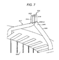
- the peel-off portion 242 becomes thinner than the coated portion 247 including the insulating film. Accordingly, the arc portions 245(b) that are parts of the coated portions 247 interfere with each other, and accordingly, a gap 248 is formed in the bonding portion 243.
- the peel-off portions 242 can be brought into contact with each other without generating a gap in the bonding portion 243. Accordingly, the bonding can be stabilized, and the reliability can be improved.
- the peeling-off is performed up to the insulating film of the arc portion, it is easy to secure a sufficient peel-off length in the longitudinal direction. As a result, the insulating film can be prevented from being damaged due to welding, and the straight portion 244 can be shortened, whereby the coil end is lowered.
- faces (vertical side faces) adjacent to the faces on which the peel-off portions 242 face each other have no relation to the interference, the peel-off distance can be shortened, whereby the insulating property is improved.
- the peel-off shape according to this embodiment may be applied only to the faces on which the peel-off portions face each other. In such a case, the peel-off shape of the other faces may be peeled off so as not to cause any damage of the insulating film at the time of bonding depending on the bonding method.
- the present invention can be applied to coils having mutually different pitches depending on the coils.
- the present invention can be applied to a case where one coil is molded to be twisted, and the other coil is a coil having the shape of a straight line for which twisted molding is not performed.
- the peel-off shape according to this embodiment is applied to the coil that is molded to be twisted.
- a segment conductor that is formed in the shape of a straight line in the welding-side coil end group 239(b) and does not include the arc portion 245(a) may be peeled off to a degree for which the insulating film is not damaged at the time of bonding.
- FIG. 9 is a diagram in which neutral lines are connected to each other using a rectangular wire having substantially the same diameter.
- the connection illustrated in the figure may be arranged in any one of the coil end groups 239(a) and (b) illustrated in FIG. 4 .
- the peel-off shape of the end portion of the connecting wire 281 includes a peel-off portion 242 that is peeled off up to the straight portion 244, the arc portion 245(a) connecting the straight portion 244 and a connecting part 282 or a part of the arc portion 245(a).
- the peel-off portion 242 may include a part of the connecting part 282.
- the peel-off portion 242 is arranged also in the connecting wire 281. As a result, when the length of the peel-off portion 242 of the neutral line 280 is sufficiently arranged, the coated portions 247 do not interfere with each other, and the peel-off portions 242 can be brought into contact with each other.
- the connecting wire 281 is used for the connection between the neutral lines 280, and the bonding portions 243 are arranged in the peel-off portions 242 and are bonded through TIG welding or the like, whereby a connection having high stability and high reliability can be made.
- the peel-off shape according to this embodiment may be applied only to the faces on which the peel-off portions face each other.
- the peel-off shape of the other faces may be peeled off so as not to cause any damage of the insulating film at the time of bonding depending on the bonding method.
- this embodiment can be applied to a case where rectangular wires having a substantially same diameter are used so as to connect coils protruding from mutually-different slots.
- the neutral line 280 is illustrated in the shape of a straight line, the shape of the neutral line 280 is not limited at all.
- the stability of the conductor bonding portion can be improved.
- the reliability of the connection of the neutral line is improved, and accordingly, the fracture of the connection portion of the neutral line can be suppressed.
- the rotating electrical machine itself may be inoperative, in this embodiment, the fracture of the neutral line is suppressed, whereby the reliability of the rotating electrical machine can be significantly improved.
- the rotating electrical machine is appropriate as a drive motor of an electric vehicle.
- the rotating electrical machine can be applied to a pure electric vehicle that is driven only by the rotating electrical machine or a hybrid vehicle that is driven by both an engine and the rotating electrical machine.
- a motor for driving a vehicle has been described above as an example, the present invention is not limited to the motor for driving a vehicle and may be applied to various motors. In addition, the present invention is not limited to the motor and may be applied to various rotating electrical machines such as a power generator and the like. In addition, the present invention is not limited to the above-described embodiments at all as long as the features of the present invention are maintained.
Landscapes
- Engineering & Computer Science (AREA)
- Power Engineering (AREA)
- Transportation (AREA)
- Mechanical Engineering (AREA)
- Manufacturing & Machinery (AREA)
- Life Sciences & Earth Sciences (AREA)
- Sustainable Development (AREA)
- Sustainable Energy (AREA)
- Windings For Motors And Generators (AREA)
- Manufacture Of Motors, Generators (AREA)
Applications Claiming Priority (2)
| Application Number | Priority Date | Filing Date | Title |
|---|---|---|---|
| JP2010291549A JP2012139075A (ja) | 2010-12-28 | 2010-12-28 | 回転電機 |
| PCT/JP2011/079524 WO2012090792A1 (fr) | 2010-12-28 | 2011-12-20 | Machine électrique tournante |
Publications (1)
| Publication Number | Publication Date |
|---|---|
| EP2660956A1 true EP2660956A1 (fr) | 2013-11-06 |
Family
ID=46382903
Family Applications (1)
| Application Number | Title | Priority Date | Filing Date |
|---|---|---|---|
| EP11854308.1A Withdrawn EP2660956A1 (fr) | 2010-12-28 | 2011-12-20 | Machine électrique tournante |
Country Status (6)
| Country | Link |
|---|---|
| US (1) | US20130300246A1 (fr) |
| EP (1) | EP2660956A1 (fr) |
| JP (1) | JP2012139075A (fr) |
| CN (1) | CN103283123A (fr) |
| BR (1) | BR112013016576A2 (fr) |
| WO (1) | WO2012090792A1 (fr) |
Cited By (4)
| Publication number | Priority date | Publication date | Assignee | Title |
|---|---|---|---|---|
| EP3327903A1 (fr) * | 2016-11-25 | 2018-05-30 | Delta Electronics, Inc. | Stator |
| EP3346586A4 (fr) * | 2015-09-02 | 2019-04-17 | Hitachi Automotive Systems, Ltd. | Bobine de stator, stator la comprenant, et machine électrique tournante équipée de ce stator |
| WO2019115059A1 (fr) * | 2017-12-13 | 2019-06-20 | Robert Bosch Gmbh | Procédé de dénudage d'un conducteur électrique et stator d'une machine électrique |
| WO2021122488A1 (fr) * | 2019-12-20 | 2021-06-24 | Valeo Equipements Electriques Moteur | Conducteur électrique pour une pièce bobinée de machine électrique tournante |
Families Citing this family (18)
| Publication number | Priority date | Publication date | Assignee | Title |
|---|---|---|---|---|
| JP5842856B2 (ja) | 2013-04-08 | 2016-01-13 | 株式会社デンソー | 回転電機の固定子 |
| JP6080964B2 (ja) * | 2013-09-18 | 2017-02-15 | 三菱電機株式会社 | 回転電機の固定子 |
| FR3020521B1 (fr) * | 2014-04-29 | 2016-06-03 | Nicolas Langlard | Stator de machine electrique tournante muni d'un bobinage optimise |
| JP6416655B2 (ja) * | 2015-02-24 | 2018-10-31 | 日立オートモティブシステムズ株式会社 | 回転電機の固定子 |
| US20160254718A1 (en) * | 2015-02-26 | 2016-09-01 | Nidec Copal Corporation | Segment conductors, stator, rotating electrical machine, and vehicle and method of manufacturing the segment conductors |
| US10305335B2 (en) * | 2016-07-14 | 2019-05-28 | Hitachi Automotive Systems, Ltd. | Stator for rotating electrical machine and rotating electrical machine |
| JP2019140839A (ja) * | 2018-02-14 | 2019-08-22 | トヨタ自動車株式会社 | 回転電機の製造方法 |
| CN108566053A (zh) * | 2018-08-02 | 2018-09-21 | 常州市奥华机电制造有限公司 | 一种铜扁线电枢的焊接装置 |
| JP6846391B2 (ja) * | 2018-09-12 | 2021-03-24 | 本田技研工業株式会社 | 電線セグメント及びステータ |
| JP6752323B1 (ja) * | 2019-04-10 | 2020-09-09 | 三菱電機株式会社 | 回転電機の固定子巻線およびその製造方法 |
| JP6798583B1 (ja) * | 2019-06-10 | 2020-12-09 | ダイキン工業株式会社 | 回転電気機械 |
| WO2021059426A1 (fr) * | 2019-09-26 | 2021-04-01 | 株式会社 東芝 | Bobine et machine dynamoélectrique |
| FR3103649B1 (fr) * | 2019-11-26 | 2025-03-14 | Nidec Psa Emotors | Stator de machine électrique tournante avec bobinage asymétrique |
| KR102654699B1 (ko) * | 2020-05-06 | 2024-04-05 | 엘지마그나 이파워트레인 주식회사 | 스테이터 및 이의 제조 방법 |
| JP7513450B2 (ja) * | 2020-07-20 | 2024-07-09 | 日立Astemo株式会社 | 回転電機および回転電機の製造方法 |
| JP7190524B2 (ja) | 2021-03-29 | 2022-12-15 | 本田技研工業株式会社 | ステータ及びステータの製造方法 |
| JP2023017570A (ja) * | 2021-07-26 | 2023-02-07 | 株式会社デンソー | 固定子、及び固定子の製造方法 |
| CN118975102A (zh) * | 2022-06-02 | 2024-11-15 | 日立安斯泰莫株式会社 | 旋转电机的定子、旋转电机的定子的制造方法 |
Family Cites Families (10)
| Publication number | Priority date | Publication date | Assignee | Title |
|---|---|---|---|---|
| JP3769990B2 (ja) * | 1999-08-06 | 2006-04-26 | 株式会社デンソー | 導体セグメント接合型の回転電機及びその製造方法 |
| JP4042386B2 (ja) * | 2000-11-06 | 2008-02-06 | 株式会社デンソー | 車両用回転電機 |
| US6894415B2 (en) * | 2000-11-06 | 2005-05-17 | Denso Corporation | Stator arrangement of rotary electric machine |
| JP3740421B2 (ja) * | 2002-01-10 | 2006-02-01 | 株式会社日立製作所 | 回転電機と固定子導線の接続方法 |
| EP1653589A3 (fr) * | 2004-11-01 | 2010-05-12 | ALSTOM Technology Ltd | Dispositif pour isoler un conducteur électrique |
| JP4654068B2 (ja) * | 2005-05-24 | 2011-03-16 | 日立オートモティブシステムズ株式会社 | 接合電線と接合電線の加工方法,回転電機の固定子と回転電機の固定子の製造方法及び接合電線製造装置 |
| JP4412330B2 (ja) * | 2007-02-09 | 2010-02-10 | 株式会社デンソー | 回転電機の固定子巻線およびその製造方法 |
| JP2010098832A (ja) * | 2008-10-16 | 2010-04-30 | Denso Corp | 車両用回転電機 |
| JP5586969B2 (ja) * | 2010-01-21 | 2014-09-10 | 株式会社デンソー | 回転電機の固定子 |
| JP5510709B2 (ja) * | 2010-01-22 | 2014-06-04 | 株式会社デンソー | 回転電機の固定子 |
-
2010
- 2010-12-28 JP JP2010291549A patent/JP2012139075A/ja active Pending
-
2011
- 2011-12-20 EP EP11854308.1A patent/EP2660956A1/fr not_active Withdrawn
- 2011-12-20 CN CN2011800636793A patent/CN103283123A/zh active Pending
- 2011-12-20 BR BR112013016576A patent/BR112013016576A2/pt not_active IP Right Cessation
- 2011-12-20 US US13/976,755 patent/US20130300246A1/en not_active Abandoned
- 2011-12-20 WO PCT/JP2011/079524 patent/WO2012090792A1/fr not_active Ceased
Non-Patent Citations (1)
| Title |
|---|
| See references of WO2012090792A1 * |
Cited By (8)
| Publication number | Priority date | Publication date | Assignee | Title |
|---|---|---|---|---|
| EP3346586A4 (fr) * | 2015-09-02 | 2019-04-17 | Hitachi Automotive Systems, Ltd. | Bobine de stator, stator la comprenant, et machine électrique tournante équipée de ce stator |
| US10666109B2 (en) | 2015-09-02 | 2020-05-26 | Hitachi Automotive Systems, Ltd. | Stator coil, stator including said stator coil, and rotating electric machine including said stator |
| EP3327903A1 (fr) * | 2016-11-25 | 2018-05-30 | Delta Electronics, Inc. | Stator |
| US10404123B2 (en) | 2016-11-25 | 2019-09-03 | Delta Electronics, Inc. | Stator |
| WO2019115059A1 (fr) * | 2017-12-13 | 2019-06-20 | Robert Bosch Gmbh | Procédé de dénudage d'un conducteur électrique et stator d'une machine électrique |
| WO2021122488A1 (fr) * | 2019-12-20 | 2021-06-24 | Valeo Equipements Electriques Moteur | Conducteur électrique pour une pièce bobinée de machine électrique tournante |
| FR3105640A1 (fr) * | 2019-12-20 | 2021-06-25 | Valeo Equipements Electriques Moteur | conducteur électrique pour une pièce bobinée de machine électrique tournante |
| US12609514B2 (en) | 2019-12-20 | 2026-04-21 | Valeo Equipements Electriques Moteur | Electrical conductor for a rotating electrical machine wound component |
Also Published As
| Publication number | Publication date |
|---|---|
| US20130300246A1 (en) | 2013-11-14 |
| CN103283123A (zh) | 2013-09-04 |
| JP2012139075A (ja) | 2012-07-19 |
| BR112013016576A2 (pt) | 2016-09-27 |
| WO2012090792A1 (fr) | 2012-07-05 |
Similar Documents
| Publication | Publication Date | Title |
|---|---|---|
| EP2660956A1 (fr) | Machine électrique tournante | |
| EP2639933B1 (fr) | Machine dynamoélectrique | |
| US20140184011A1 (en) | Stator for Rotating Electrical Machine and Rotating Electrical Machine | |
| EP2698901B1 (fr) | Stator de machine électrique, moteur électrique équipé de ce stator et véhicule électrique équipé du moteur électrique | |
| US9287742B2 (en) | Spoke permanent magnet machine with reduced torque ripple and method of manufacturing thereof | |
| EP3079234B1 (fr) | Machine électrique tournante | |
| US8446061B2 (en) | Rotating electric machine having stator core with slot insulation encircling first and second coils | |
| US8492947B2 (en) | Terminal module for rotating electric machine having a guide portion, rotating electric machine, and manufacturing method thereof | |
| JP5040303B2 (ja) | 回転電機 | |
| US7348706B2 (en) | Stator assembly for an electric machine and method of manufacturing the same | |
| JP5635470B2 (ja) | 回転電機および回転電機の製造方法 | |
| US20100001609A1 (en) | Rotating electric machine | |
| JP6793257B2 (ja) | 回転電機の固定子、及び回転電機 | |
| JP6777760B2 (ja) | 回転電機用の固定子、及び回転電機 | |
| CN110086280B (zh) | 定子及具备该定子的旋转电机 | |
| TW201742356A (zh) | 軸向間隙型旋轉電機 | |
| US6967554B2 (en) | Coil for a rotary electric machine | |
| JP5805046B2 (ja) | 車両用電動機および車両用発電機 | |
| WO2023199711A1 (fr) | Machine électrique tournante | |
| US20240146127A1 (en) | Rotor for a rotary electric machine | |
| EP4224682A1 (fr) | Ensemble de connexion électrique pour un rotor excité séparément | |
| JP4547228B2 (ja) | 3相回転電機 |
Legal Events
| Date | Code | Title | Description |
|---|---|---|---|
| PUAI | Public reference made under article 153(3) epc to a published international application that has entered the european phase |
Free format text: ORIGINAL CODE: 0009012 |
|
| 17P | Request for examination filed |
Effective date: 20130729 |
|
| AK | Designated contracting states |
Kind code of ref document: A1 Designated state(s): AL AT BE BG CH CY CZ DE DK EE ES FI FR GB GR HR HU IE IS IT LI LT LU LV MC MK MT NL NO PL PT RO RS SE SI SK SM TR |
|
| DAX | Request for extension of the european patent (deleted) | ||
| STAA | Information on the status of an ep patent application or granted ep patent |
Free format text: STATUS: THE APPLICATION HAS BEEN WITHDRAWN |
|
| 18W | Application withdrawn |
Effective date: 20160303 |