EP2661607B1 - Tête de lecture d'encodeur - Google Patents
Tête de lecture d'encodeur Download PDFInfo
- Publication number
- EP2661607B1 EP2661607B1 EP12701259.9A EP12701259A EP2661607B1 EP 2661607 B1 EP2661607 B1 EP 2661607B1 EP 12701259 A EP12701259 A EP 12701259A EP 2661607 B1 EP2661607 B1 EP 2661607B1
- Authority
- EP
- European Patent Office
- Prior art keywords
- encoder
- scale
- opening
- encoder scale
- readhead
- Prior art date
- Legal status (The legal status is an assumption and is not a legal conclusion. Google has not performed a legal analysis and makes no representation as to the accuracy of the status listed.)
- Not-in-force
Links
- 239000000463 material Substances 0.000 claims description 7
- 230000009471 action Effects 0.000 claims description 4
- UFNIBRDIUNVOMX-UHFFFAOYSA-N 2,4'-dichlorobiphenyl Chemical compound C1=CC(Cl)=CC=C1C1=CC=CC=C1Cl UFNIBRDIUNVOMX-UHFFFAOYSA-N 0.000 description 4
- 230000003287 optical effect Effects 0.000 description 4
- 229920003023 plastic Polymers 0.000 description 4
- VYZAMTAEIAYCRO-UHFFFAOYSA-N Chromium Chemical compound [Cr] VYZAMTAEIAYCRO-UHFFFAOYSA-N 0.000 description 3
- 230000008859 change Effects 0.000 description 3
- 238000000576 coating method Methods 0.000 description 3
- 238000003780 insertion Methods 0.000 description 3
- 230000037431 insertion Effects 0.000 description 3
- 238000009434 installation Methods 0.000 description 3
- 238000000034 method Methods 0.000 description 3
- 238000000926 separation method Methods 0.000 description 3
- ZGHQUYZPMWMLBM-UHFFFAOYSA-N 1,2-dichloro-4-phenylbenzene Chemical compound C1=C(Cl)C(Cl)=CC=C1C1=CC=CC=C1 ZGHQUYZPMWMLBM-UHFFFAOYSA-N 0.000 description 2
- 230000008901 benefit Effects 0.000 description 2
- 239000011248 coating agent Substances 0.000 description 2
- 230000000694 effects Effects 0.000 description 2
- 230000005489 elastic deformation Effects 0.000 description 2
- 230000035699 permeability Effects 0.000 description 2
- 230000001681 protective effect Effects 0.000 description 2
- AIURIRUDHVDRFQ-UHFFFAOYSA-N 1,2,3,4-tetrachloro-5-(2-chlorophenyl)benzene Chemical compound ClC1=CC=CC=C1C1=CC(Cl)=C(Cl)C(Cl)=C1Cl AIURIRUDHVDRFQ-UHFFFAOYSA-N 0.000 description 1
- QVWUJLANSDKRAH-UHFFFAOYSA-N 1,2,4-trichloro-3-(2,3-dichlorophenyl)benzene Chemical compound ClC1=CC=CC(C=2C(=C(Cl)C=CC=2Cl)Cl)=C1Cl QVWUJLANSDKRAH-UHFFFAOYSA-N 0.000 description 1
- 230000008878 coupling Effects 0.000 description 1
- 238000010168 coupling process Methods 0.000 description 1
- 238000005859 coupling reaction Methods 0.000 description 1
- 229920002457 flexible plastic Polymers 0.000 description 1
- 239000000314 lubricant Substances 0.000 description 1
- 238000005259 measurement Methods 0.000 description 1
- 230000008569 process Effects 0.000 description 1
- 230000008439 repair process Effects 0.000 description 1
- 230000000717 retained effect Effects 0.000 description 1
- 238000005096 rolling process Methods 0.000 description 1
- 230000035939 shock Effects 0.000 description 1
Images



Classifications
-
- G—PHYSICS
- G01—MEASURING; TESTING
- G01D—MEASURING NOT SPECIALLY ADAPTED FOR A SPECIFIC VARIABLE; ARRANGEMENTS FOR MEASURING TWO OR MORE VARIABLES NOT COVERED IN A SINGLE OTHER SUBCLASS; TARIFF METERING APPARATUS; MEASURING OR TESTING NOT OTHERWISE PROVIDED FOR
- G01D5/00—Mechanical means for transferring the output of a sensing member; Means for converting the output of a sensing member to another variable where the form or nature of the sensing member does not constrain the means for converting; Transducers not specially adapted for a specific variable
- G01D5/12—Mechanical means for transferring the output of a sensing member; Means for converting the output of a sensing member to another variable where the form or nature of the sensing member does not constrain the means for converting; Transducers not specially adapted for a specific variable using electric or magnetic means
- G01D5/14—Mechanical means for transferring the output of a sensing member; Means for converting the output of a sensing member to another variable where the form or nature of the sensing member does not constrain the means for converting; Transducers not specially adapted for a specific variable using electric or magnetic means influencing the magnitude of a current or voltage
- G01D5/142—Mechanical means for transferring the output of a sensing member; Means for converting the output of a sensing member to another variable where the form or nature of the sensing member does not constrain the means for converting; Transducers not specially adapted for a specific variable using electric or magnetic means influencing the magnitude of a current or voltage using Hall-effect devices
- G01D5/145—Mechanical means for transferring the output of a sensing member; Means for converting the output of a sensing member to another variable where the form or nature of the sensing member does not constrain the means for converting; Transducers not specially adapted for a specific variable using electric or magnetic means influencing the magnitude of a current or voltage using Hall-effect devices influenced by the relative movement between the Hall device and magnetic fields
-
- G—PHYSICS
- G01—MEASURING; TESTING
- G01D—MEASURING NOT SPECIALLY ADAPTED FOR A SPECIFIC VARIABLE; ARRANGEMENTS FOR MEASURING TWO OR MORE VARIABLES NOT COVERED IN A SINGLE OTHER SUBCLASS; TARIFF METERING APPARATUS; MEASURING OR TESTING NOT OTHERWISE PROVIDED FOR
- G01D5/00—Mechanical means for transferring the output of a sensing member; Means for converting the output of a sensing member to another variable where the form or nature of the sensing member does not constrain the means for converting; Transducers not specially adapted for a specific variable
- G01D5/26—Mechanical means for transferring the output of a sensing member; Means for converting the output of a sensing member to another variable where the form or nature of the sensing member does not constrain the means for converting; Transducers not specially adapted for a specific variable characterised by optical transfer means, i.e. using infrared, visible, or ultraviolet light
- G01D5/32—Mechanical means for transferring the output of a sensing member; Means for converting the output of a sensing member to another variable where the form or nature of the sensing member does not constrain the means for converting; Transducers not specially adapted for a specific variable characterised by optical transfer means, i.e. using infrared, visible, or ultraviolet light with attenuation or whole or partial obturation of beams of light
- G01D5/34—Mechanical means for transferring the output of a sensing member; Means for converting the output of a sensing member to another variable where the form or nature of the sensing member does not constrain the means for converting; Transducers not specially adapted for a specific variable characterised by optical transfer means, i.e. using infrared, visible, or ultraviolet light with attenuation or whole or partial obturation of beams of light the beams of light being detected by photocells
- G01D5/347—Mechanical means for transferring the output of a sensing member; Means for converting the output of a sensing member to another variable where the form or nature of the sensing member does not constrain the means for converting; Transducers not specially adapted for a specific variable characterised by optical transfer means, i.e. using infrared, visible, or ultraviolet light with attenuation or whole or partial obturation of beams of light the beams of light being detected by photocells using displacement encoding scales
- G01D5/34746—Linear encoders
- G01D5/34753—Carriages; Driving or coupling means
Definitions
- the present invention relates to an encoder readhead for reading an associated encoder scale, and in particular to an improved encoder readhead that may be more easily attached to, and/or removed from, an associated encoder scale comprising a rod having a substantially circular cross-section.
- Encoder readheads for measuring the position, or change in position, of an encoder scale in the form of a piston rod are known.
- an encoder readhead comprises a rectangular housing having a central circular opening or passageway.
- one end of the piston rod is passed through the circular opening of the housing and the readhead is then secured to a stationary part of an apparatus.
- the rod moves back and forth through the opening in the housing.
- a readhead e.g. an array of Hall sensors
- the encoder scale e.g. formed by a series of magnetic markings
- the position, or change in position, of the readhead relative to the associated piston rod can then be determined and this information used for controlling the apparatus.
- An encoded cylinder comprising a rod having a scale is described in US6327791 .
- EP1878931 describes a sliding guide arrangement that may be attached to an intermediate part of the track.
- encoder tapes and associated tape readers are known.
- US2005/0246916 describes a encoder tape reader system that comprises a reader and a shoe to support the tape whilst it is being read. The tape may be slid into a side opening of the tape reader system and supported by the shoe arrangement.
- Scale reading apparatus having a dust-proof means to protect the moving parts is described in US4063086 .
- a rotary encoder incorporated into the bearing of a steering wheel shaft is described in EP443940 .
- an encoder readhead for a linear encoder system as defined in claim 1.
- the present invention thus provides an encoder readhead comprising a housing.
- the housing defines an opening or passageway in which an encoder scale in the form of a rod having a circular cross-section can be captured, thereby attaching the encoder readhead to the encoder scale.
- the opening is preferably an elongate passageway or channel (e.g. a substantially cylindrical channel) that defines an axial direction along which the captured encoder scale can slide back and forth.
- the longitudinal axis of the associated encoder scale, when captured in the opening preferably substantially coincides with the axial direction of the opening.
- the housing thus captures the encoder scale in the opening in a manner that substantially prevents lateral (side to side) motion of the encoder scale relative to the readhead but permits the captured encoder scale to slide back and forth relative to the readhead (i.e. axial motion is allowed).
- the readhead of the present invention also comprises a scale reader for reading a portion of an encoder scale located in the opening.
- the scale reader and encoder scale may be of any suitable type.
- the encoder scale may comprise a series of magnetic markings that can be measured using a magnetic scale reader. Further details of preferred types of scale reader and encoder scale are described in more detail below.
- the encoder readhead of the present invention includes a housing with an access portion that allows the encoder scale to be inserted into, and/or removed from, the opening in a non-axial direction.
- the access portion allows the encoder scale to be inserted into, and/or removed from, the opening by a relative movement between the housing and the encoder scale in a direction substantially perpendicular to the axial direction (i.e. from a radial direction).
- the geometry of the housing in the section perpendicular to the axial direction of the opening allows the readhead to be attached to the rod of the encoder scale from a radial direction.
- an encoder readhead of the present invention in contrast to prior art readheads, means that there is no need to pass the opening formed in the housing over an end of the encoder scale (e.g. piston rod) in order to attach it to, or remove it from, the encoder scale. Instead, the access portion allows the encoder readhead to be attached to, and/or removed from, a side of an encoder scale.
- the encoder readhead of the present invention thus has the advantage that it can be attached to (and/or detached from) the encoder scale whilst each end of that encoder scale remains mechanically connected to any mechanical apparatus in which it is installed. This has the advantage of making encoder readhead installation, repair and servicing easier to perform.
- the encoder readhead of the present invention can be attached to, and detached from, a piston rod of a machine without having to disassemble the machine to mechanically unload the piston rod.
- the access portion is provided as defined in claim 1.
- a hinged portion may be attached to the housing that can be opened and closed to provide access to the opening.
- the access portion comprises a gap or slit formed in a side wall of the housing.
- the gap preferably extends along the length of the opening.
- the gap provides side (radial) access to the opening that allows the scale member to be inserted into, and/or removed from, the opening through the gap. The gap can thus be passed or slid over the side of the encoder scale thereby allowing the opening to capture the encoder scale and/or allowing the encoder scale to be removed from the housing.
- the housing defines a gap having at least one elastically deformable wall portion.
- the gap may be slightly smaller than the relevant dimension of the encoder scale portion that is to be passed therethrough.
- the at least one elastically deformable wall portion permits the gap to expand (e.g. when forced into engagement with an encoder scale), thereby allowing the encoder scale to pass through it.
- the gap advantageously comprises a fluted entrance that causes the gap to expand when pressed into engagement with an encoder scale. In this manner, the gap can be forced to expand (i.e. by elastic deformation of said at least one elastically deformable wall portion) by the action of pressing the encoder scale into the gap.
- the encoder scale is pressed into the gap with a certain force it passes through the gap (e.g.
- the encoder scale when the encoder scale has passed through the gap it is then captured in the opening.
- This capturing process advantageously occurs by a snap-fit or clip-on type of action.
- the encoder scale may also be detached from the readhead in a similar manner. For example, a lateral detachment force may be applied between the readhead and encoder scale in the direction of the gap. After the lateral force exceeds a certain threshold, the gap elastically expands and the encoder scale is released from the opening.
- the housing defines an opening having at least one elastically deformable wall portion. If the housing defines a gap having at least one elastically deformable wall portion, the gap and opening may share one or more common elastically deformable portions. In other words, a single elastically deformable portion may provide an elastically deformable wall of the gap and an elastically deformable wall of the opening. Preferably, the at least one elastically deformable wall portion of the opening is biased into engagement with an encoder scale located within the opening thereby capturing the encoder scale.
- the encoder readhead may comprise one or more rollers for contacting the encoder scale (i.e. to provide rolling contact with the elongate rod).
- the encoder readhead comprises a slider (e.g. a plastic slider) that has one or more surfaces that define the opening. The slider thus provides sliding contact with the rod.
- a spring for example a leaf spring, may also be included. The spring is preferably arranged to bias the one or more surfaces of the slider into contact with an encoder scale thereby capturing the encoder scale in the opening.
- the slider may include the one or more elastically deformable wall portions that are mentioned above. In such a case, the spring may act on such elastically deformable wall portions and bias their inner surfaces into contact with the encoder scale.
- a captured encoder scale is arranged to fit tightly or snugly within the opening.
- the opening may have a radius that is substantially the same as, or slightly less than, the radius of the rod that forms the encoder scale.
- the captured encoder scale is held tightly enough within the opening to minimise lateral movements, but not so tightly as to prevent the required sliding motion between the encoder readhead and encoder scale.
- the force with which the encoder scale is held within the opening is preferably substantially constant, thereby ensuring the sliding friction remains substantially invariant with use.
- the encoder scale is held in the opening against one or more surfaces of the opening that have a fixed position relative to the scale reader. Conveniently, such fixed position surfaces may be adjacent the scale reader.
- the encoder scale is forced into engagement with the fixed position surfaces by one or more biasing surfaces; the force applied by the biasing surface(s) to the encoder scale preferably being substantially constant.
- a substantially constant ride-height between the scale reader and the associated encoder scale can be maintained as they slide back and forth relative to one another.
- a readhead casing affixed to the apparatus includes a bushing that carries a scale reader and pushes it into engagement with the encoder scale.
- the bushing tolerances thus define the required ride-height tolerance meaning that it is typically necessary to provide substantially higher ride-height tolerances when using a prior art readhead of this type than are necessary when employing the arrangement of the present invention.
- the opening may be defined by one or more surfaces that engage and capture an encoder scale.
- at least one such surface comprises a material having a low coefficient of friction.
- at least some of the surfaces that engage the encoder scale may be formed from a low friction plastic material, such as PA6.
- a lubricant, such as oil, or a surface coating may conveniently be provided to reduce friction. These surfaces may thus provide the slider described above.
- the encoder scale is elongate and forms part of a linear encoder.
- the encoder scale also performs a load bearing function.
- the encoder scale may comprise a piston rod for use in hydraulic or pneumatic actuators.
- the opening is preferably configured for use with the required encoder scale.
- the shape and dimensions e.g.
- the opening are preferably matched to the encoder scale with which it is to be used.
- the cross-section of the opening may be substantially circular, part circular and/or include a plurality of surfaces spaced apart in a circular arrangement.
- the opening may completely surround a section of a captured encoder scale.
- the opening only partially surrounds a captured encoder scale; e.g. one or more gaps or slots of the type described above may be provided.
- the scale reader provided in the readhead may be of any suitable type.
- the scale reader may be an optical scale reader for reading optical markings on an associated optical scale.
- the scale reader is a magnetic scale reader.
- the scale reader may comprise at least one magnetic sensor.
- the scale reader comprises a plurality of magnetic sensors (e.g. Hall sensors) that may be arranged in a linear array.
- the scale reader can read the magnetic scale markings provided on an associated encoder scale.
- the associated encoder scale may include so-called active magnetic markings; for example, a series of magnets arranged with alternating north and south poles.
- the encoder scale comprises a so-called passive magnetic scale in which the scale comprises a series of markings or regions that have a different magnetic permeability than the surrounding material.
- a magnet may be provided in the readhead; the magnetic sensors can then be used to sense the change in the magnetic field generated by the magnet in the presence of the regions of different magnetic permeability of the encoder scale.
- a hard, protective, coating e.g. chrome
- the scale reader may be arranged to read incremental encoder scale and/or absolute encoder scale.
- the encoder readhead advantageously comprises a mounting for attaching the encoder readhead to an associated machine.
- the mounting is stiff in a direction parallel to the axial direction.
- the mounting is compliant in one or more directions (or all directions) non-parallel to the axial direction.
- the mounting introduces some play to account for mechanical stresses and strains within the machine in which the encoder readhead is mounted.
- motion in the axial direction is substantially prevented thereby ensuring the effect of such play on the positional information being measured by the encoder readhead is minimised.
- the mounting of the readhead only carries the mechanical load of the readhead.
- the readhead and mounting are preferably arranged not to form part of a load bearing path of the machine in which it is installed.
- the encoder scale may be a piston rod; in this case a mechanical force may be passed through the piston rod but this force is preferably not transmitted through the readhead (i.e. the readhead preferably remains separate from the parts of the machine that carry the mechanical load).
- the present invention also extends to encoder apparatus that comprises both an encoder readhead as described above and an encoder scale.
- the encoder scale may have any of the properties outlined above.
- the present invention also extends to a machine comprising the encoder apparatus.
- the machine may comprise a piston rod that forms the encoder scale. In use, the piston rod may then also carry a mechanical load.
- the present invention also extends to a method of attaching an encoder readhead to an encoder scale comprising an elongate rod having a substantially circular cross-section, the encoder readhead comprising a housing having an opening for capturing the encoder scale and the encoder scale being dimensioned to be retained within the opening, wherein the encoder scale can be inserted into, and/or removed from, the opening by a relative movement between the housing and the encoder scale in a direction other than the axial direction (e.g. from a radial direction).
- the encoder readhead and/or encoder scale may have any of the features described above.
- an encoder readhead comprising: a housing having an opening for attaching the encoder readhead to an associated encoder scale, the opening, in use, capturing the encoder scale and allowing the encoder scale to slide back and forth through the opening, and a scale reader for reading a portion of an encoder scale located in the opening, wherein the housing includes an access portion that permits the housing to be attached to, and/or detached from, the associated encoder scale from a side thereof.
- the encoder readhead and/or encoder scale may have any of the features described above.
- an encoder readhead comprising a casing that is attachable to an associated encoder scale and a scale reader for reading a portion of an encoder scale located adjacent to the casing, wherein the casing including means for slideably capturing the encoder scale, said means allowing the readhead to be attached to, and/or detached from, the associated encoder scale from a side thereof.
- an encoder readhead that comprises: a housing having an opening for capturing an encoder scale, the opening defining an axial direction along which a captured encoder scale can slide back and forth; and a scale reader for reading a portion of an encoder scale located in the opening, wherein the housing includes an access portion that allows the encoder scale to be inserted into, and/or removed from, the opening by a relative movement between the housing and the encoder scale in a non-axial direction (i.e. a direction other than the axial direction).
- the housing defines an opening or passageway in which an appropriately dimensioned encoder scale (e.g.
- an encoder scale in the form of a rod having a circular cross-section can be captured, thereby attaching the encoder readhead to the encoder scale.
- Any type of encoder scale may be provided.
- the encoder scale may be elongate and form part of a linear encoder.
- the encoder scale may have a square, circular, or rectangular cross-section.
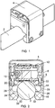
- FIG 1 there is shown a schematic view of a linear encoder system of the present invention that comprises an encoder scale in the form of a rod 2 having a circular cross-section.
- An encoder readhead 4 is attached to, and can slide back and forth along, the rod 2.
- the rod 2 has scale marking (not shown) formed along its length and the encoder readhead 4 comprises a scale reader (not shown) for reading the scale markings.
- FIG 2 shows a cross-section through the linear encoder system of figure 1 .
- the encoder readhead 4 comprises a housing 6 that contains a first printed circuit board (PCB) 8 that carries a scale reader 10 comprising a plurality of Hall sensors.
- the housing also contains a second PCB 12 comprising a processor for processing the signals generated by the scale reader.
- a cable is provided for carrying positional information from the second PCB 12 of the readhead to an associated interface or controller.
- the housing 6 comprises an outer U-shaped leaf spring 14.
- a slider 16 made from a flexible plastic material is compressed between the (lower) free ends of the leaf spring 14.
- the slider 16 comprises a first pair of internal surfaces 20 and 22 and a second pair of internal surfaces 24 and 26.
- the internal surfaces 20, 22, 24 and 26 are part circular and together define an elongate channel or opening 18 through the readhead that is dimensioned to capture the associated circular rod 2.
- Slots 28 and 29 are also provided in the slider 16 between opposed ones of the first and second pairs of internal surface.
- the slots 28 and 29 act as points of (elastic) weakness in the slider such that the spring force applied by the surrounding U-shaped leaf spring 14 biases each of the second pair of internal surfaces 24 and 26 towards the rod 2.
- the bias force is selected to be sufficient to ensure the slider portion 16 securely captures the rod 2 (i.e. ensuring the rod 2 stays attached to the readhead 4 during normal use) but low enough to permit the rod 2 to slide back and forth through the opening 18.
- an access portion is provided in the form of a gap 30 formed along the length of the opening 18.
- the gap 30 is located between the second pair of internal surfaces 24 and 26 and allows the rod 2 to be inserted into, and removed from, the opening (i.e. through the gap 30).
- the second pair of internal surfaces 24 and 26 are, as explained above, spring biased and can be separated by a sufficient amount to permit insertion/removal of the rod 2.
- External angled edges 32 are provided on the outer facing surface of the slider 16 to aid such separation of the internal surfaces 24 and 26 during rod insertion into the opening 18.
- the gap 30 of the readhead 4 can thus be pressed against the side of the rod 2, thereby causing the internal surfaces 24 and 26 to separate whereupon the rod can enter the opening 18. Once located in the opening 18, the internal surfaces 24 and 26 spring back and engage the rod thereby capturing it.
- Figure 3 shows an expanded view of the rod 2 and scale reader 10 that are described above with reference to figure 2 .
- readhead 4 allows a substantially invariant gap to be maintained between the scale formed on the rod 2 and the scale reader 10 within the readhead.
- the separation between the scale reader 10 of the readhead and the scale formed on the rod 2 is different for different types of sensors and when reading scales of different pitch or grating period.
- the scale pitch is small and sensing distance tolerances may be very low.
- the sensing distance may be defined as 0.2 to 0.4 times the grating period of the associated scale formed in or on the rod 2.
- a grating period of 0.5mum thus defines a sensing distance of 0.1 to 0.2 mm.
- the sensing distance is the distance between Hall sensors of the scale reader and the magnetic markings formed on the rod.
- the actual physical gap (or ride-height 42) between the scale protection layer and the readhead may need to be as low as 0.02mm when additional materials located between the hall sensor and scale markings (such as edges of the readhead and any tough surface coatings, such as hard chrome, that are provided on the rod) are taken into account.
- the optimum ride-height is maintained along the whole rod length. It is also preferred, to prevent damage, for there to be no contact between the first PCB 8 that carries the scale reader 10 and the rod 2; i.e. the ride-height is preferably set to be greater than zero. It is also important that the correct ride-height is maintained in harsh environments when the encoder system is subjected to vibrations, shocks and temperature variations.
- the readhead is attached to the rod by the clamping force applied by the U-shaped leaf spring 14 through the slider 16.
- This arrangement forces the rod 2 into tight engagement with the first pair of internal surfaces 20 and 22 that have a substantially invariant position relative to the first PCB 8.
- the slider16 locks or sets the distance between the rod 2 and the Hall sensors provided on the first PCB 8.
- the desired ride-height can be predefined during assembly of the first PCB 8 and the slider 16.
- the slider 16 is maintained in sliding contact with the rod, and is therefore preferably made of material with good sliding properties. It may, for example, comprise the plastic PA6 with dispersed oil. This provides a low coefficient of friction and a low amount of wear is experienced when sliding against a protective chrome layer of the rod 2. When the rod 2 is captured in the opening 18 by the slider 16, the only free direction of movement of the rod 2 is axial.
- the present inventors have recognised the need of machine operators to have an easy way of maintaining and servicing an installed readhead. This is particularly the case for an encoder scale as described above that takes the form of a piston rod in an actuator. Rather than using prior art readheads that must be installed and removed over an end of the rod, the present invention allows the installation or replacement of a readhead on a rod from a radial direction (i.e. from the side of the rod). This means the need to uncouple the rod from the mechanical equipment in which it is installed is removed thereby considerable easing the replacement or servicing procedure. It should, however, be noted that the readhead could still be installed or removed over the end of a rod (i.e. from the axial direction) if desired.
- Figure 4 shows cut through view of the readhead 4 prior to it being mounted to the rod 2.
- the slider 16 provides an opening 18 (which is empty in figure 4 ) for capturing the rod 2.
- the opening 18 is defined by the first and second pairs of internal surfaces 20, 22, 24 and 26 that are dimensioned, in the absence of an inserted rod, to have a radius that is slightly smaller than that of the rod.
- the gap 30 located between the second pair of internal surfaces 24 and 26 allows the rod 2 to be inserted into the opening.
- the external angled edges 32 provided on the outer facing surfaces of the slider 16 are arranged to engage the rod prior to insertion.
- Forcing the rod against the external angled edges 32 causes the second pair of internal surfaces 24 and 26 to separate from one another (i.e. the bias provided the leaf spring is overcome) and the rod 2 passes through the expanded gap 30. Once the rod 2 has entered the opening 18, the second pair of internal surfaces 24 and 26 spring back and engage the rod 2 thereby capturing it in the opening. This can be seen to provide a clip-on or snap fit action.
- Figure 5 shows the rod 2 captured in the opening 18 of the slider 16.
- Figure 6 shows, with the associated rod 2 omitted for clarity, how the gap 30 in the slider 16 can be expanded to permit the rod 2 to pass into (or back out of) the opening 18.
- a piston rod in an actuator generally has some play, which is typically greater than the tolerance in the sensing distance.
- Figure 7 shows how the above described readhead 4 can be attached to a fixed body (e.g. an actuator flange) of the mechanical system in which it is to be used.
- Figure 7 is a view through the readhead 4 and rod 2 in the plane I-1 that is shown in figure 5 .
- the coupling or mounting between the readhead 4 and the fixed body comprises a thin flexible rod 40 having a first end 42 fixed to a point on the slider 16 and a second end 44 that carries and adapter element 46.
- the adapter element 46 can be affixed to the fixed body of the machine (e.g. the actuator flange or cylinder body).
- the thin flexible rod 40 can bend in all directions, except along its elongate axis (i.e. it is stiff axially). This arrangement prevents any substantial movement of the readhead 4 in the axial direction (i.e.
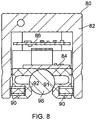
- an alternative encoder readhead 80 is shown that comprises a rigid housing 82 that comprises a first PCB 84 comprising a scale reader.
- a second PCB 86 comprising a processor is also provided.
- a plastic slider 88 is also included that is similar to the slider 16 described in the examples outlined above.
- the readhead 80 includes coil springs 90 that act to bias surface 92 and 94 into contact with the piston rod 96; these coil springs 90 provided the biasing force that is provided by the U-shaped leaf spring 14 in the above described embodiments.
- Figure 9 shows a further encoder readhead 110 and figure 10 shows a section through the readhead 110.
- the readhead 110 comprises a housing and opening that are defined by a carriage 112 and various spaced apart rollers.
- the carriage 112 comprises a first pair of rollers 114 that are radially separated from a second pair of rollers 116.
- a scale reader unit 118 is also attached to the carriage.
- a spring loaded arm member 120 protrudes from the carriage and carries a single roller 122 at is distal end.
- a piston rod 124 is captured in the opening formed between the first and second pair of rollers 114 and 116 and the roller 122.
- the spring loaded arm member 120 can be deflected sufficiently to allow the readhead 110 to be clipped on and off of the piston rod 124 as required, thereby forming an access portion. Once clipped on to the piston rod, the readhead 110 may also be attached (e.g. screwed) to a clutch washer 126 that remains slideably attached to the piston rod 124. It should also be noted that any one or more of the rollers forming the first and second pair of rollers 114 and 116 and roller 122 could be replaced with one or more sliding surfaces.
- the invention could be applied to any type of encoder system.
- the invention could be used as part of an optical encoder system.
Landscapes
- Physics & Mathematics (AREA)
- General Physics & Mathematics (AREA)
- Transmission And Conversion Of Sensor Element Output (AREA)
Claims (13)
- Tête de lecture de codeur (4;80; 110) pour système de codage linéaire avec règle de codage (2; 124), comprenant :un logement (6;82) ayant une ouverture (18) servant à saisir ladite règle de codage (2; 124) comprenant une tige allongée ayant une coupe transversale sensiblement circulaire et des repères réalisés sur sa longueur, l'ouverture (18) définissant une direction axiale le long de laquelle une règle de codage saisie (2;124) peut coulisser vers l'arrière et l'avant ; et un lecteur de règle (10) servant à lire une partie d'une règle de codage (2;124) située dans l'ouverture (18),caractérisé en ce que le logement (6;82) comprend une partie d'accès (30) permettant à la règle de codage (2;124) d'être introduite dans, et/ou retirée de, l'ouverture (18) par un mouvement relatif entre le logement (6;82) et la règle de codage (2;124) dans une direction non axiale, la partie d'accès (30) étant réalisée par :(A) un espace dans une paroi latérale du logement (6;82) qui permet à la règle de codage (2;124) d'être introduite dans, et/ou retirée de, l'ouverture (18) au travers de l'espace, le logement ayant au moins une partie de paroi élastiquement déformable (24,26) qui permet à l'espace (30) de se dilater, la règle de codage (2;124) pouvant ainsi passer au travers de celui-ci, ou bien par(B) une partie à charnière fixée au logement qui peut être ouverte et fermée afin de donner accès à l'ouverture.
- Tête de lecture de codeur selon la revendication 1, dans laquelle la partie d'accès (30) permet à la règle de codage (2;124) d'être introduite dans, et/ou retirée de, l'ouverture (18) par un mouvement relatif entre le logement (6;82) et la règle de codage (2;124) dans une direction sensiblement perpendiculaire à la direction axiale.
- Tête de lecture de codeur selon la revendication 1, dans laquelle l'espace (30) comprend une entrée cannelée (32) qui fait que l'espace (30) se dilate quand il est comprimé en prise avec une règle de codage (2;124).
- Tête de lecture de codeur selon l'une quelconque des revendications précédentes, dans laquelle, quand la règle de codage (2,124) est forcée en prise avec l'espace (30), celle-ci traverse l'espace (30) et est saisie dans l'ouverture (18) par une action d'encliquetage.
- Tête de lecture de codeur selon l'une quelconque des revendications précédentes, dans laquelle le logement (6;82) définit une ouverture (18) ayant au moins une partie de paroi élastiquement déformable (24,26), dans laquelle la ou les parois élastiquement déformables (24,26) de l'ouverture (18) sont contraintes en prise avec une règle de codage (2,124) située dans l'ouverture (18) la règle de codage (2,124) étant ainsi saisie.
- Tête de lecture de codeur selon la revendication 5, comprenant un ressort à lame (14) et un coulisseau intérieur (16) ayant une ou plusieurs surfaces définissant l'ouverture (18), dans laquelle le ressort à lame (16) est agencé pour contraindre la ou les surfaces en contact avec une règle de codage (2,124) la règle de codage étant ainsi saisie dans l'ouverture (18).
- Tête de lecture de codeur selon l'une quelconque des revendications précédentes, dans laquelle une règle de codage saisie s'ajuste parfaitement dans l'ouverture (18) et est tenue contre une ou plusieurs surfaces (20,22) ayant une position relative fixe par rapport au lecteur de règle (10) une hauteur de course sensiblement constante étant ainsi maintenue entre le lecteur de règle (10) et la règle de codage associée (2,124) lorsqu'ils coulissent vers l'arrière et l'avant l'un par rapport à l'autre.
- Tête de lecture de codeur selon l'une quelconque des revendications précédentes, dans laquelle l'ouverture (18) comprend au moins une surface (16) servant à mettre en prise une règle de codage saisie, dans laquelle ladite au moins une surface (16) comprend un matériau à faible coefficient de friction.
- Tête de lecture de codeur selon l'une quelconque des revendications précédentes, dans laquelle l'ouverture (18) entoure seulement partiellement une règle de codage saisie (2,124).
- Tête de lecture de codeur selon l'une quelconque des revendications précédentes, dans laquelle le lecteur de règle (10) comprend au moins un capteur magnétique servant à lire une règle de codage comprenant une série de repères magnétiques.
- Tête de lecture de codeur selon l'une quelconque des revendications précédentes, comprenant une monture (40) servant à fixer la tête de lecture de codeur à un dispositif, dans laquelle la monture (40) est sensiblement rigide dans une direction parallèle à la direction axiale et élastique dans une ou plusieurs directions non parallèles à la direction axiale.
- Appareil de codage comprenant : une tête de lecture de codeur selon l'une quelconque des revendications précédentes et une règle de codage (2,124) comprenant une tige allongée ayant une coupe transversale sensiblement circulaire.
- Machine comprenant l'appareil de codage selon la revendication 12, la machine comprenant une tige de piston qui forme la règle de codage, dans laquelle, lors de l'utilisation, la tige de piston porte également une charge mécanique.
Applications Claiming Priority (2)
| Application Number | Priority Date | Filing Date | Title |
|---|---|---|---|
| GBGB1100190.6A GB201100190D0 (en) | 2011-01-07 | 2011-01-07 | Encoder readhead apparatus |
| PCT/GB2012/000012 WO2012093253A1 (fr) | 2011-01-07 | 2012-01-06 | Appareil du type tête de lecture d'encodeur |
Publications (2)
| Publication Number | Publication Date |
|---|---|
| EP2661607A1 EP2661607A1 (fr) | 2013-11-13 |
| EP2661607B1 true EP2661607B1 (fr) | 2017-07-05 |
Family
ID=43663882
Family Applications (1)
| Application Number | Title | Priority Date | Filing Date |
|---|---|---|---|
| EP12701259.9A Not-in-force EP2661607B1 (fr) | 2011-01-07 | 2012-01-06 | Tête de lecture d'encodeur |
Country Status (6)
| Country | Link |
|---|---|
| US (1) | US9032638B2 (fr) |
| EP (1) | EP2661607B1 (fr) |
| JP (1) | JP5993870B2 (fr) |
| CN (1) | CN103299163B (fr) |
| GB (1) | GB201100190D0 (fr) |
| WO (1) | WO2012093253A1 (fr) |
Families Citing this family (7)
| Publication number | Priority date | Publication date | Assignee | Title |
|---|---|---|---|---|
| US9829298B2 (en) * | 2011-06-24 | 2017-11-28 | Pi Tape Texas, Llc | Optical readout device to provide visual information |
| US11009374B2 (en) * | 2015-12-03 | 2021-05-18 | Renishaw Plc | Encoder |
| USD800811S1 (en) * | 2016-05-25 | 2017-10-24 | Zapadoceska Univerzita V Plzni | Linear guideway |
| JP6686124B1 (ja) * | 2018-12-26 | 2020-04-22 | Thk株式会社 | 転がり案内装置のセンサ取付け構造 |
| GB202015773D0 (en) * | 2020-10-05 | 2020-11-18 | Renishaw Plc | Apparatus, disc, and method of manufacture |
| IT202000026708A1 (it) * | 2020-11-09 | 2022-05-09 | Givi Misure S R L | Riga ottica o magnetica per misure lineari |
| US11846529B2 (en) | 2021-04-19 | 2023-12-19 | Joral Llc | Magnetic rack and pinion linear magnetic encoder and position sensing system |
Citations (3)
| Publication number | Priority date | Publication date | Assignee | Title |
|---|---|---|---|---|
| EP0443940A2 (fr) * | 1990-02-22 | 1991-08-28 | Snr Roulements | Dispositif pour déterminer le sens et la vitesse de rotation d'une colonne de direction. |
| US5234269A (en) * | 1989-02-24 | 1993-08-10 | The Torrington Company | Antifriction bearing with a clip-on sensor |
| US6327791B1 (en) * | 1999-06-09 | 2001-12-11 | The Government Of The United States As Represented By The Secretary Of Commerce | Chain code position detector |
Family Cites Families (23)
| Publication number | Priority date | Publication date | Assignee | Title |
|---|---|---|---|---|
| JPS5635765Y2 (fr) * | 1975-09-22 | 1981-08-24 | ||
| JPS61209303A (ja) | 1985-03-13 | 1986-09-17 | Sony Magnescale Inc | 磁気スケ−ルの記録並に検出方法及び装置 |
| JP3269846B2 (ja) * | 1992-04-16 | 2002-04-02 | キヤノン株式会社 | 記録装置 |
| JP3271626B2 (ja) * | 1992-04-14 | 2002-04-02 | キヤノン株式会社 | 記録装置 |
| JP3331280B2 (ja) * | 1995-07-31 | 2002-10-07 | 日本トムソン株式会社 | 直動転がり案内ユニット |
| JPH0953638A (ja) | 1995-08-11 | 1997-02-25 | Nippon Thompson Co Ltd | 位置検出装置並びにこれを具備した軌道台ユニット及び案内ユニット |
| JPH1061664A (ja) | 1996-08-15 | 1998-03-06 | Nippon Thompson Co Ltd | 直動転がり案内ユニット |
| JPH11351907A (ja) * | 1998-04-06 | 1999-12-24 | Matsushita Electric Ind Co Ltd | 磁気式エンコーダ |
| JP3605511B2 (ja) | 1998-05-15 | 2004-12-22 | 山洋電気株式会社 | 光学式エンコーダ付きモータ |
| JP3660925B2 (ja) | 2002-10-23 | 2005-06-15 | ファナック株式会社 | エンコーダ用回転ディスク |
| JP2004286662A (ja) * | 2003-03-24 | 2004-10-14 | Komatsu Ltd | 磁気センサを用いた絶対位置検出装置 |
| US7281339B2 (en) | 2004-05-06 | 2007-10-16 | Universal Instruments Corporation | Encoder system |
| US7290647B2 (en) | 2005-03-10 | 2007-11-06 | Thk Co., Ltd. | Guide apparatus |
| KR101238991B1 (ko) | 2005-03-18 | 2013-03-04 | 티에치케이 가부시끼가이샤 | 안내 장치 |
| US7205530B2 (en) * | 2005-05-16 | 2007-04-17 | Renco Encoders, Inc. | Encoder device and apparatus for gapping and centering an encoder device |
| EP1752851A1 (fr) | 2005-08-12 | 2007-02-14 | Schneeberger Holding AG | Glissière linéaire avec des moyens de mesure |
| JP4496154B2 (ja) * | 2005-10-31 | 2010-07-07 | 株式会社リコー | ロータリーエンコーダ、ローラ部材、ベルト搬送装置、画像形成装置 |
| DE102008032419A1 (de) * | 2008-07-10 | 2010-01-14 | Dr. Johannes Heidenhain Gmbh | Drehgeber und Baureihe von Drehgebern |
| JP5255395B2 (ja) | 2008-10-01 | 2013-08-07 | Thk株式会社 | スケール付運動案内装置及びスケール付運動案内装置用軌道部材 |
| US20100162582A1 (en) | 2008-12-30 | 2010-07-01 | Chih-Mao Shiao | Positioning Device of a Magnetic Ruler |
| GB0903535D0 (en) * | 2009-03-02 | 2009-04-08 | Rls Merilna Tehnika D O O | Encoder readhead |
| DE102010061737A1 (de) * | 2010-11-22 | 2012-05-24 | Baumer Innotec Ag | Absolutwertgeber mit Sprungstelle in kodierter Absolutlage |
| EP2746730B1 (fr) * | 2012-12-21 | 2015-11-18 | SICK STEGMANN GmbH | Système d'entraînement avec un encodeur angulaire |
-
2011
- 2011-01-07 GB GBGB1100190.6A patent/GB201100190D0/en not_active Ceased
-
2012
- 2012-01-06 US US13/976,675 patent/US9032638B2/en active Active
- 2012-01-06 JP JP2013547904A patent/JP5993870B2/ja not_active Expired - Fee Related
- 2012-01-06 WO PCT/GB2012/000012 patent/WO2012093253A1/fr not_active Ceased
- 2012-01-06 CN CN201280004700.7A patent/CN103299163B/zh not_active Expired - Fee Related
- 2012-01-06 EP EP12701259.9A patent/EP2661607B1/fr not_active Not-in-force
Patent Citations (3)
| Publication number | Priority date | Publication date | Assignee | Title |
|---|---|---|---|---|
| US5234269A (en) * | 1989-02-24 | 1993-08-10 | The Torrington Company | Antifriction bearing with a clip-on sensor |
| EP0443940A2 (fr) * | 1990-02-22 | 1991-08-28 | Snr Roulements | Dispositif pour déterminer le sens et la vitesse de rotation d'une colonne de direction. |
| US6327791B1 (en) * | 1999-06-09 | 2001-12-11 | The Government Of The United States As Represented By The Secretary Of Commerce | Chain code position detector |
Also Published As
| Publication number | Publication date |
|---|---|
| CN103299163B (zh) | 2015-09-16 |
| JP2014501930A (ja) | 2014-01-23 |
| JP5993870B2 (ja) | 2016-09-14 |
| US9032638B2 (en) | 2015-05-19 |
| GB201100190D0 (en) | 2011-02-23 |
| WO2012093253A1 (fr) | 2012-07-12 |
| CN103299163A (zh) | 2013-09-11 |
| EP2661607A1 (fr) | 2013-11-13 |
| US20130269198A1 (en) | 2013-10-17 |
Similar Documents
| Publication | Publication Date | Title |
|---|---|---|
| US9032638B2 (en) | Encoder readhead apparatus | |
| KR100194164B1 (ko) | 유압 실린더 | |
| KR102035660B1 (ko) | 힘 및/또는 부하를 측정하기 위한 측정 기구를 구비한 장치 | |
| US6578283B2 (en) | Position transducer | |
| CN103080698B (zh) | 带旋转传感器的轴承 | |
| US6668464B2 (en) | Coupling and angle encoder with such a coupling | |
| EP3384246B1 (fr) | Appareil codeur | |
| US11316418B2 (en) | Adaptive installation rotary encoder | |
| TW201546381A (zh) | 運動引導裝置 | |
| US20240295417A1 (en) | Apparatus, disc, and method of manufacture | |
| WO2012112989A1 (fr) | Support de capteur optique flottant | |
| US20050206372A1 (en) | Scale | |
| US20130293222A1 (en) | Sensor Head for an Encoder | |
| JP2012171087A (ja) | 搬送装置 | |
| JP2003232653A (ja) | 位置測定装置 | |
| EP1445584B1 (fr) | Dispositif d'echelle | |
| KR101039478B1 (ko) | 스케일장치 | |
| KR101415637B1 (ko) | 리니어 인코더 | |
| US20090106997A1 (en) | Position detector | |
| JP3484915B2 (ja) | 位置検出装置 | |
| EP4467932A1 (fr) | Dispositif de mesure | |
| US7355498B2 (en) | Construction element for locking ring magnets in bore holes | |
| WO2007052066A1 (fr) | Détecteur de position à monture flexible | |
| JP2012098130A (ja) | 移動体の位置読取装置 | |
| JP2010288339A (ja) | リニアエンコーダ |
Legal Events
| Date | Code | Title | Description |
|---|---|---|---|
| PUAI | Public reference made under article 153(3) epc to a published international application that has entered the european phase |
Free format text: ORIGINAL CODE: 0009012 |
|
| 17P | Request for examination filed |
Effective date: 20130801 |
|
| AK | Designated contracting states |
Kind code of ref document: A1 Designated state(s): AL AT BE BG CH CY CZ DE DK EE ES FI FR GB GR HR HU IE IS IT LI LT LU LV MC MK MT NL NO PL PT RO RS SE SI SK SM TR |
|
| DAX | Request for extension of the european patent (deleted) | ||
| 17Q | First examination report despatched |
Effective date: 20150910 |
|
| REG | Reference to a national code |
Ref country code: DE Ref legal event code: R079 Ref document number: 602012034155 Country of ref document: DE Free format text: PREVIOUS MAIN CLASS: G01D0005347000 Ipc: G01D0005140000 |
|
| GRAP | Despatch of communication of intention to grant a patent |
Free format text: ORIGINAL CODE: EPIDOSNIGR1 |
|
| RIC1 | Information provided on ipc code assigned before grant |
Ipc: G01D 5/14 20060101AFI20170102BHEP Ipc: G01D 5/347 20060101ALI20170102BHEP |
|
| INTG | Intention to grant announced |
Effective date: 20170202 |
|
| GRAS | Grant fee paid |
Free format text: ORIGINAL CODE: EPIDOSNIGR3 |
|
| GRAA | (expected) grant |
Free format text: ORIGINAL CODE: 0009210 |
|
| AK | Designated contracting states |
Kind code of ref document: B1 Designated state(s): AL AT BE BG CH CY CZ DE DK EE ES FI FR GB GR HR HU IE IS IT LI LT LU LV MC MK MT NL NO PL PT RO RS SE SI SK SM TR |
|
| REG | Reference to a national code |
Ref country code: GB Ref legal event code: FG4D |
|
| REG | Reference to a national code |
Ref country code: CH Ref legal event code: EP |
|
| REG | Reference to a national code |
Ref country code: AT Ref legal event code: REF Ref document number: 906908 Country of ref document: AT Kind code of ref document: T Effective date: 20170715 |
|
| REG | Reference to a national code |
Ref country code: IE Ref legal event code: FG4D |
|
| REG | Reference to a national code |
Ref country code: DE Ref legal event code: R096 Ref document number: 602012034155 Country of ref document: DE |
|
| REG | Reference to a national code |
Ref country code: NL Ref legal event code: MP Effective date: 20170705 |
|
| REG | Reference to a national code |
Ref country code: AT Ref legal event code: MK05 Ref document number: 906908 Country of ref document: AT Kind code of ref document: T Effective date: 20170705 |
|
| REG | Reference to a national code |
Ref country code: LT Ref legal event code: MG4D |
|
| PG25 | Lapsed in a contracting state [announced via postgrant information from national office to epo] |
Ref country code: SE Free format text: LAPSE BECAUSE OF FAILURE TO SUBMIT A TRANSLATION OF THE DESCRIPTION OR TO PAY THE FEE WITHIN THE PRESCRIBED TIME-LIMIT Effective date: 20170705 Ref country code: AT Free format text: LAPSE BECAUSE OF FAILURE TO SUBMIT A TRANSLATION OF THE DESCRIPTION OR TO PAY THE FEE WITHIN THE PRESCRIBED TIME-LIMIT Effective date: 20170705 Ref country code: NO Free format text: LAPSE BECAUSE OF FAILURE TO SUBMIT A TRANSLATION OF THE DESCRIPTION OR TO PAY THE FEE WITHIN THE PRESCRIBED TIME-LIMIT Effective date: 20171005 Ref country code: HR Free format text: LAPSE BECAUSE OF FAILURE TO SUBMIT A TRANSLATION OF THE DESCRIPTION OR TO PAY THE FEE WITHIN THE PRESCRIBED TIME-LIMIT Effective date: 20170705 Ref country code: NL Free format text: LAPSE BECAUSE OF FAILURE TO SUBMIT A TRANSLATION OF THE DESCRIPTION OR TO PAY THE FEE WITHIN THE PRESCRIBED TIME-LIMIT Effective date: 20170705 Ref country code: LT Free format text: LAPSE BECAUSE OF FAILURE TO SUBMIT A TRANSLATION OF THE DESCRIPTION OR TO PAY THE FEE WITHIN THE PRESCRIBED TIME-LIMIT Effective date: 20170705 Ref country code: FI Free format text: LAPSE BECAUSE OF FAILURE TO SUBMIT A TRANSLATION OF THE DESCRIPTION OR TO PAY THE FEE WITHIN THE PRESCRIBED TIME-LIMIT Effective date: 20170705 |
|
| PG25 | Lapsed in a contracting state [announced via postgrant information from national office to epo] |
Ref country code: PL Free format text: LAPSE BECAUSE OF FAILURE TO SUBMIT A TRANSLATION OF THE DESCRIPTION OR TO PAY THE FEE WITHIN THE PRESCRIBED TIME-LIMIT Effective date: 20170705 Ref country code: GR Free format text: LAPSE BECAUSE OF FAILURE TO SUBMIT A TRANSLATION OF THE DESCRIPTION OR TO PAY THE FEE WITHIN THE PRESCRIBED TIME-LIMIT Effective date: 20171006 Ref country code: RS Free format text: LAPSE BECAUSE OF FAILURE TO SUBMIT A TRANSLATION OF THE DESCRIPTION OR TO PAY THE FEE WITHIN THE PRESCRIBED TIME-LIMIT Effective date: 20170705 Ref country code: ES Free format text: LAPSE BECAUSE OF FAILURE TO SUBMIT A TRANSLATION OF THE DESCRIPTION OR TO PAY THE FEE WITHIN THE PRESCRIBED TIME-LIMIT Effective date: 20170705 Ref country code: LV Free format text: LAPSE BECAUSE OF FAILURE TO SUBMIT A TRANSLATION OF THE DESCRIPTION OR TO PAY THE FEE WITHIN THE PRESCRIBED TIME-LIMIT Effective date: 20170705 Ref country code: BG Free format text: LAPSE BECAUSE OF FAILURE TO SUBMIT A TRANSLATION OF THE DESCRIPTION OR TO PAY THE FEE WITHIN THE PRESCRIBED TIME-LIMIT Effective date: 20171005 Ref country code: IS Free format text: LAPSE BECAUSE OF FAILURE TO SUBMIT A TRANSLATION OF THE DESCRIPTION OR TO PAY THE FEE WITHIN THE PRESCRIBED TIME-LIMIT Effective date: 20171105 |
|
| REG | Reference to a national code |
Ref country code: DE Ref legal event code: R097 Ref document number: 602012034155 Country of ref document: DE |
|
| PG25 | Lapsed in a contracting state [announced via postgrant information from national office to epo] |
Ref country code: CZ Free format text: LAPSE BECAUSE OF FAILURE TO SUBMIT A TRANSLATION OF THE DESCRIPTION OR TO PAY THE FEE WITHIN THE PRESCRIBED TIME-LIMIT Effective date: 20170705 Ref country code: DK Free format text: LAPSE BECAUSE OF FAILURE TO SUBMIT A TRANSLATION OF THE DESCRIPTION OR TO PAY THE FEE WITHIN THE PRESCRIBED TIME-LIMIT Effective date: 20170705 Ref country code: RO Free format text: LAPSE BECAUSE OF FAILURE TO SUBMIT A TRANSLATION OF THE DESCRIPTION OR TO PAY THE FEE WITHIN THE PRESCRIBED TIME-LIMIT Effective date: 20170705 |
|
| PLBE | No opposition filed within time limit |
Free format text: ORIGINAL CODE: 0009261 |
|
| STAA | Information on the status of an ep patent application or granted ep patent |
Free format text: STATUS: NO OPPOSITION FILED WITHIN TIME LIMIT |
|
| PG25 | Lapsed in a contracting state [announced via postgrant information from national office to epo] |
Ref country code: EE Free format text: LAPSE BECAUSE OF FAILURE TO SUBMIT A TRANSLATION OF THE DESCRIPTION OR TO PAY THE FEE WITHIN THE PRESCRIBED TIME-LIMIT Effective date: 20170705 Ref country code: SM Free format text: LAPSE BECAUSE OF FAILURE TO SUBMIT A TRANSLATION OF THE DESCRIPTION OR TO PAY THE FEE WITHIN THE PRESCRIBED TIME-LIMIT Effective date: 20170705 Ref country code: SK Free format text: LAPSE BECAUSE OF FAILURE TO SUBMIT A TRANSLATION OF THE DESCRIPTION OR TO PAY THE FEE WITHIN THE PRESCRIBED TIME-LIMIT Effective date: 20170705 |
|
| 26N | No opposition filed |
Effective date: 20180406 |
|
| PG25 | Lapsed in a contracting state [announced via postgrant information from national office to epo] |
Ref country code: SI Free format text: LAPSE BECAUSE OF FAILURE TO SUBMIT A TRANSLATION OF THE DESCRIPTION OR TO PAY THE FEE WITHIN THE PRESCRIBED TIME-LIMIT Effective date: 20170705 |
|
| REG | Reference to a national code |
Ref country code: CH Ref legal event code: PL |
|
| PG25 | Lapsed in a contracting state [announced via postgrant information from national office to epo] |
Ref country code: FR Free format text: LAPSE BECAUSE OF NON-PAYMENT OF DUE FEES Effective date: 20180131 Ref country code: LU Free format text: LAPSE BECAUSE OF NON-PAYMENT OF DUE FEES Effective date: 20180106 |
|
| REG | Reference to a national code |
Ref country code: IE Ref legal event code: MM4A |
|
| REG | Reference to a national code |
Ref country code: FR Ref legal event code: ST Effective date: 20180928 |
|
| REG | Reference to a national code |
Ref country code: BE Ref legal event code: MM Effective date: 20180131 |
|
| PG25 | Lapsed in a contracting state [announced via postgrant information from national office to epo] |
Ref country code: CH Free format text: LAPSE BECAUSE OF NON-PAYMENT OF DUE FEES Effective date: 20180131 Ref country code: LI Free format text: LAPSE BECAUSE OF NON-PAYMENT OF DUE FEES Effective date: 20180131 Ref country code: BE Free format text: LAPSE BECAUSE OF NON-PAYMENT OF DUE FEES Effective date: 20180131 |
|
| PG25 | Lapsed in a contracting state [announced via postgrant information from national office to epo] |
Ref country code: IE Free format text: LAPSE BECAUSE OF NON-PAYMENT OF DUE FEES Effective date: 20180106 |
|
| PG25 | Lapsed in a contracting state [announced via postgrant information from national office to epo] |
Ref country code: MC Free format text: LAPSE BECAUSE OF FAILURE TO SUBMIT A TRANSLATION OF THE DESCRIPTION OR TO PAY THE FEE WITHIN THE PRESCRIBED TIME-LIMIT Effective date: 20170705 |
|
| PG25 | Lapsed in a contracting state [announced via postgrant information from national office to epo] |
Ref country code: MT Free format text: LAPSE BECAUSE OF NON-PAYMENT OF DUE FEES Effective date: 20180106 |
|
| PG25 | Lapsed in a contracting state [announced via postgrant information from national office to epo] |
Ref country code: TR Free format text: LAPSE BECAUSE OF FAILURE TO SUBMIT A TRANSLATION OF THE DESCRIPTION OR TO PAY THE FEE WITHIN THE PRESCRIBED TIME-LIMIT Effective date: 20170705 |
|
| PG25 | Lapsed in a contracting state [announced via postgrant information from national office to epo] |
Ref country code: PT Free format text: LAPSE BECAUSE OF FAILURE TO SUBMIT A TRANSLATION OF THE DESCRIPTION OR TO PAY THE FEE WITHIN THE PRESCRIBED TIME-LIMIT Effective date: 20170705 Ref country code: HU Free format text: LAPSE BECAUSE OF FAILURE TO SUBMIT A TRANSLATION OF THE DESCRIPTION OR TO PAY THE FEE WITHIN THE PRESCRIBED TIME-LIMIT; INVALID AB INITIO Effective date: 20120106 |
|
| PG25 | Lapsed in a contracting state [announced via postgrant information from national office to epo] |
Ref country code: CY Free format text: LAPSE BECAUSE OF FAILURE TO SUBMIT A TRANSLATION OF THE DESCRIPTION OR TO PAY THE FEE WITHIN THE PRESCRIBED TIME-LIMIT Effective date: 20170705 Ref country code: MK Free format text: LAPSE BECAUSE OF NON-PAYMENT OF DUE FEES Effective date: 20170705 |
|
| PG25 | Lapsed in a contracting state [announced via postgrant information from national office to epo] |
Ref country code: AL Free format text: LAPSE BECAUSE OF FAILURE TO SUBMIT A TRANSLATION OF THE DESCRIPTION OR TO PAY THE FEE WITHIN THE PRESCRIBED TIME-LIMIT Effective date: 20170705 |
|
| PGFP | Annual fee paid to national office [announced via postgrant information from national office to epo] |
Ref country code: IT Payment date: 20230120 Year of fee payment: 12 Ref country code: GB Payment date: 20230124 Year of fee payment: 12 Ref country code: DE Payment date: 20230127 Year of fee payment: 12 |
|
| REG | Reference to a national code |
Ref country code: DE Ref legal event code: R119 Ref document number: 602012034155 Country of ref document: DE |
|
| GBPC | Gb: european patent ceased through non-payment of renewal fee |
Effective date: 20240106 |
|
| PG25 | Lapsed in a contracting state [announced via postgrant information from national office to epo] |
Ref country code: DE Free format text: LAPSE BECAUSE OF NON-PAYMENT OF DUE FEES Effective date: 20240801 |
|
| PG25 | Lapsed in a contracting state [announced via postgrant information from national office to epo] |
Ref country code: GB Free format text: LAPSE BECAUSE OF NON-PAYMENT OF DUE FEES Effective date: 20240106 |
|
| PG25 | Lapsed in a contracting state [announced via postgrant information from national office to epo] |
Ref country code: GB Free format text: LAPSE BECAUSE OF NON-PAYMENT OF DUE FEES Effective date: 20240106 Ref country code: DE Free format text: LAPSE BECAUSE OF NON-PAYMENT OF DUE FEES Effective date: 20240801 |
|
| PG25 | Lapsed in a contracting state [announced via postgrant information from national office to epo] |
Ref country code: IT Free format text: LAPSE BECAUSE OF NON-PAYMENT OF DUE FEES Effective date: 20240106 |