EP2664521A1 - Plattenstruktur für ein fahrzeug - Google Patents
Plattenstruktur für ein fahrzeug Download PDFInfo
- Publication number
- EP2664521A1 EP2664521A1 EP11855306.4A EP11855306A EP2664521A1 EP 2664521 A1 EP2664521 A1 EP 2664521A1 EP 11855306 A EP11855306 A EP 11855306A EP 2664521 A1 EP2664521 A1 EP 2664521A1
- Authority
- EP
- European Patent Office
- Prior art keywords
- portions
- members
- vehicle
- roof
- disposed
- Prior art date
- Legal status (The legal status is an assumption and is not a legal conclusion. Google has not performed a legal analysis and makes no representation as to the accuracy of the status listed.)
- Granted
Links
- 239000011347 resin Substances 0.000 claims description 16
- 229920005989 resin Polymers 0.000 claims description 16
- 239000000853 adhesive Substances 0.000 claims description 12
- 230000001070 adhesive effect Effects 0.000 claims description 12
- 230000002093 peripheral effect Effects 0.000 claims description 7
- 230000000717 retained effect Effects 0.000 claims description 7
- 230000000694 effects Effects 0.000 description 12
- 210000000078 claw Anatomy 0.000 description 11
- 230000002787 reinforcement Effects 0.000 description 7
- 230000003014 reinforcing effect Effects 0.000 description 3
- 239000000463 material Substances 0.000 description 2
- 239000002184 metal Substances 0.000 description 2
- 230000004048 modification Effects 0.000 description 2
- 238000012986 modification Methods 0.000 description 2
- 238000000034 method Methods 0.000 description 1
- 238000000465 moulding Methods 0.000 description 1
- 230000000153 supplemental effect Effects 0.000 description 1
- 238000003466 welding Methods 0.000 description 1
Images


Classifications
-
- B—PERFORMING OPERATIONS; TRANSPORTING
- B62—LAND VEHICLES FOR TRAVELLING OTHERWISE THAN ON RAILS
- B62D—MOTOR VEHICLES; TRAILERS
- B62D25/00—Superstructure or monocoque structure sub-units; Parts or details thereof not otherwise provided for
- B62D25/06—Fixed roofs
-
- B—PERFORMING OPERATIONS; TRANSPORTING
- B62—LAND VEHICLES FOR TRAVELLING OTHERWISE THAN ON RAILS
- B62D—MOTOR VEHICLES; TRAILERS
- B62D25/00—Superstructure or monocoque structure sub-units; Parts or details thereof not otherwise provided for
- B62D25/08—Front or rear portions
- B62D25/10—Bonnets or lids, e.g. for trucks, tractors, busses, work vehicles
-
- B—PERFORMING OPERATIONS; TRANSPORTING
- B62—LAND VEHICLES FOR TRAVELLING OTHERWISE THAN ON RAILS
- B62D—MOTOR VEHICLES; TRAILERS
- B62D29/00—Superstructures, understructures, or sub-units thereof, characterised by the material thereof
- B62D29/001—Superstructures, understructures, or sub-units thereof, characterised by the material thereof characterised by combining metal and synthetic material
- B62D29/005—Superstructures, understructures, or sub-units thereof, characterised by the material thereof characterised by combining metal and synthetic material preformed metal and synthetic material elements being joined together, e.g. by adhesives
-
- B—PERFORMING OPERATIONS; TRANSPORTING
- B62—LAND VEHICLES FOR TRAVELLING OTHERWISE THAN ON RAILS
- B62D—MOTOR VEHICLES; TRAILERS
- B62D29/00—Superstructures, understructures, or sub-units thereof, characterised by the material thereof
- B62D29/04—Superstructures, understructures, or sub-units thereof, characterised by the material thereof predominantly of synthetic material
- B62D29/043—Superstructures
Definitions
- the present invention relates to a vehicular panel structure for a roof panel or a hood.
- a left and right pair of roof side rails are disposed extending in a vehicle front-and-rear direction on both vehicle width direction end portions of a roof portion positioned on the upper portion of the vehicle, and a front header and a rear header disposed extending in the vehicle width direction are joined to front end portions and rear end portions, respectively, of the roof side rails.
- a resin roof panel is joined to metal vehicle frame members, such as the front header, the rear header, and the roof side rails.
- Ribs are formed on an undersurface side (the opposite side of the design surface) of the roof panel along the vehicle front-and-rear direction on both end sides in the vehicle width direction, and because of this, the rigidity of the roof panel is raised.
- front header and rear header are joined to the roof side rails in such a way as to form substantial right angles as seen in a vehicle plan view, but this prior art does not have the function of maintaining the angles formed by either the front header or the rear header with the roof side rails.
- a first aspect of the present invention provides a vehicular panel structure applied to a vehicle equipped with a pair of side members that configure a vehicle frame member and are disposed extending along a vehicle front-and-rear direction or a vehicle up-and-down direction and cross members that configure the vehicle frame member, are disposed extending along a vehicle width direction, and bridge the pair of side members, the vehicular panel structure comprising: a resin panel member that is joined to the vehicle frame member; and high-rigidity portions that are disposed on the panel member in positions straddling the side members and the cross members and are higher in rigidity than other sections of the panel member.
- the resin panel member is joined to the vehicle frame member configured to include the pair of side members that are disposed extending along the vehicle front-and-rear direction or the vehicle up-and-down direction and the cross members that are disposed extending along the vehicle width direction and bridge the pair of side members.
- the "panel member” include a roof panel, a hood, and a back door.
- the high-rigidity portions that are higher in rigidity than the other sections of the panel member are disposed on the panel member in positions straddling the side members and the cross members.
- examples of "on the panel member in positions straddling the side members and the cross members” include a case where the high-rigidity portions enter in between the side members and the cross members and a case where the high-rigidity portions interconnect the side members and the cross members.
- a reaction force with respect to the compressive load can be obtained with the high-rigidity portions.
- the side members or the cross members try to deform in the direction in which the angles formed by the side members and the cross members become narrower or the direction in which the angles formed by the side members and the cross members become wider, but because a reaction force with respect to the compressive load or the tensile load is obtained with the high-rigidity portions, even when resin is used for the panel member, the angles formed by the side members and the cross members become maintained via the high-rigidity portions disposed on the panel member. Consequently, changes in the angles between the side members and the cross members are prevented or suppressed.
- vehicle rigidity becomes higher and steering stability and NV performance improve. Further, because vehicle rigidity becomes higher, even if one side of the vehicle were to run over a bump during travel, torsional deformation of the vehicle via the vehicle frame member is prevented or suppressed.
- a second aspect of the present invention is the first aspect of the present invention, wherein the high-rigidity portions may be ribs that have been made thicker than the thickness of other sections of the panel member.
- the high-rigidity portions are ribs disposed on the panel member.
- the ribs may be molded separately from the panel member and thereafter integrated with the panel member, or the ribs may be molded integrally with the panel member.
- secondary processing such as integrating the two parts becomes necessary, but materials differing between the ribs and the panel member can be used.
- moldability is good because it suffices just to dispose the ribs on the panel member, and a reduction in cost can be achieved because secondary processing such as integrating the two parts is unnecessary.
- a third aspect of the present invention is the second aspect of the present invention, wherein engaging portions that engage with engaged portions disposed on the side members and the cross members may be disposed in the ribs.
- the engaged portions are disposed on the side members and the cross members, and the engaging portions that engage with the engaged portions are disposed in the ribs. For this reason, by causing the engaged portions of the side members and the cross members to engage with the engaging portions of the panel member to engage with each other, the side members and the cross members become interconnected and reinforced by the ribs. Because of this, even when resin is used for the panel member, the angles formed by the side members and the cross members become maintained via the ribs, and changes in the angles between the side members and the cross members are prevented or suppressed.
- a fourth aspect of the present invention is the third aspect of the present invention, wherein the engaged portions may be head portions disposed on through members that penetrate and are retained in through holes formed in the side members or the cross members, with the head portions projecting from surfaces of the side member or the cross members, and the engaging portions may be recessed portions into which the head portions are inserted.
- the through members penetrate and are retained in the through holes formed in the side members or the cross members.
- the head portions of the through members project from the surfaces of the side members or the cross members, and the head portions are inserted into the recessed portions disposed in the ribs.
- the through members are retained with respect to the side members or the cross members, so in a state in which the head portions of the through members have been inserted into the recessed portions in the ribs, uplift of the panel member can be prevented or suppressed via the through members because the head portions and the recessed portions are secured.
- a fifth aspect of the present invention is the third aspect of the present invention, wherein the engaged portions may be peripheral edge portions of through holes formed in the side members or the cross members, and the engaging portions may be projections that penetrate the through holes and are locked on the peripheral edge portions of the through holes.
- the projections are disposed on the ribs, penetrate the through holes formed in the side members or the cross members, and are locked on the peripheral edge portions of the through holes, the projections become retained with respect to the side members or the cross members. For this reason, uplift of the panel member can be prevented or suppressed via the projections.
- a sixth aspect of the present invention is any one of the first to fifth aspects of the present invention, wherein the side members may be disposed extending in the vehicle front-and-rear direction, and the panel member may be a roof panel.
- a seventh aspect of the present invention is any one of the second to sixth aspects of the present invention, wherein an adhesive may be applied to lengthwise direction outer sides of the ribs.
- An eighth aspect of the present invention is any one of the first to seventh aspects of the present invention, wherein the cross members may be configured to include a front header portion placed on a front end portion of the resin roof panel and a rear header portion placed on a rear end portion of the resin roof panel, and the high-rigidity portions may be disposed at least on the rear header portion.
- the cross members are configured to include the front header portion placed on the front end portion of the resin roof panel and the rear header portion placed on the rear end portion of the resin roof panel.
- a sedan type of vehicle there are few differences in deformation between the vehicle front side and the vehicle rear side of the vehicle frame member configuring the vehicle roof portion, but in a hatchback type of vehicle, the vehicle rear side of the vehicle frame member tends to deform more easily than the vehicle front side of the vehicle frame member. For this reason, by reinforcing at least the rear header portion side, changes in angles between vehicle frame members can be suppressed with the necessary minimum configuration.
- the first aspect has the excellent effect that changes in angles between vehicle frame members can be suppressed.
- the second aspect has the excellent effect that a reduction in cost can be achieved by molding the high-rigidity portions integrally with the panel member.
- the third aspect has the excellent effect that changes in angles between vehicle frame members can be suppressed with a simple configuration.
- the fourth aspect has the excellent effect that uplift of the panel member can be suppressed.
- the fifth aspect has the excellent effect that a reduction in cost can be achieved.
- the sixth aspect has the excellent effect that the function of suppressing changes in angles between vehicle frame members can be sufficiently exhibited.
- the seventh aspect has the excellent effect that the reaction force with respect to a tensile load can be increased.
- the eighth aspect has the excellent effect that suppressing changes in angles between vehicle frame members can be obtained at a low cost.
- arrow FR represents a front direction in a vehicle front-and-rear direction
- arrow UP represents an up direction in a vehicle up-and-down direction.
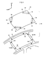
- FIG. 1 there is shown a schematic exploded perspective view of a metal vehicular frame member 11 and a resin roof panel 28 serving as a panel member positioned at the upper portion of a vehicle, with the vehicular frame member 11 and the roof panel 28 configuring a vehicular roof structure 10 serving as a vehicular panel structure, and in FIG. 2 , there is shown a state in which the roof panel 28 has been joined to the vehicular frame member 11.
- a left and right pair of roof side rails 12 serving as side members are disposed extending along the vehicle front-and-rear direction on both vehicle width direction end portions of the vehicular frame member 11. Further, a front header 14 and a rear header 16 serving as cross members are disposed extending along the vehicle width direction on a vehicle front end portion and rear end portion of the vehicular frame member 11 and bridge the pair of roof side rails 12.
- each of the roof side rails 12 is disposed with a roof side rail inner member 18 placed on a cabin inner side and a roof side rail outer member 20 placed on a cabin outer side, and a roof side reinforcement member 22 is disposed between the roof side rail inner member 18 and the roof side rail outer member 20.
- Flange portions 18A, 22A, and 20A are disposed on both vehicle width direction end portions of the roof side rail inner member 18, the roof side reinforcement member 22, and the roof side rail outer member 20, respectively, and the flange portions 18A, 22A, and 20A are joined to each other. Because of this, a closed cross section is formed between the roof side rail inner member 18 and the roof side reinforcement member 22, and a closed cross section is formed between the roof side reinforcement member 22 and the roof side rail outer member 20.
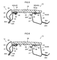
- each of the front header 14 and the rear header 16 (in FIG. 3 , the rear header 16 side is shown) is disposed with a header lower member 24 placed on the cabin inner side and a header upper member 26 placed on the cabin outer side.
- Flange portions 24A and 26A are disposed on both vehicle front-and-rear direction end portions of the header lower member 24 and the header upper member 26, respectively, and the flange portions 24A and 26A are joined to each other. Because of this, a closed cross section is formed between the header lower member 24 and the header upper member 26.
- prismatic ribs 30 serving as high-rigidity portions are disposed integrally with the roof panel 28 on corner portions on the vehicle front end side of an undersurface side (the opposite side of the design surface) of the roof panel 28 in such a way as to straddle spaces between the front header 14 and the roof side rails 12 that the ribs 30 face.
- prismatic ribs 32 serving as high-rigidity portions are formed on corner portions on the vehicle rear end side of the roof panel 28 in such a way as to straddle spaces between the rear header 16 and the roof side rails 12.
- the vehicle front end side and the vehicle rear end side of the roof panel 28 have substantially identical configurations, so the ribs 32 on the vehicle rear end side of the roof panel 28 will be described below.
- Engaging holes 34 formed in substantially cylindrical shapes are formed as recessed portions in both lengthwise direction end sides of each of the ribs 32.
- Weld nuts 36 serving as engaged portions are welded to the upper surface of the header upper member 26 of the rear header 16 and the upper surfaces of the flange portions 20A disposed in the roof side rail outer members 20 of the roof side rails 12.
- the engaging holes 34 are disposed in positions opposing the weld nuts 36, and the weld nuts 36 are made insertable into (made engageable with) the engaging holes 34.
- the roof panel 28 is joined (secured) to the headers 38 and the roof side rails 12 via an adhesive 40 disposed on the peripheral edge side of the roof panel 28.
- the adhesive 40 is also disposed on the lengthwise direction outer sides of the ribs 32 and in spaces arising between the engaging holes 34 and the weld nuts 36.
- the ribs 30 and 32 are formed on each of the corner portions on the undersurface side of the roof panel 28 in such a way as to straddle the spaces between the headers 38 (the front header 14 and the rear header 16) and the roof side rails 12. Additionally, the engaging holes 34 are formed in both lengthwise direction end sides of each of the ribs 32 (regarding the ribs 30, description will be omitted because they have a configuration that is substantially identical to that of the ribs 32), and the weld nuts 36 disposed on the headers 38 and the roof side rails 12 are engaged with the engaging holes 34.
- the thickness of the sections where the ribs 32 are disposed becomes thicker than the thickness of other sections of the roof panel 28. Because of this, the roof panel 28 can be reinforced and the rigidity of the roof panel 28 can be raised. Consequently, vehicle rigidity becomes higher and steering stability and NV performance improve.
- headers 38 and the roof side rails 12 are interconnected by causing the engaging holes 34 formed in the ribs 32 disposed on the roof panel 28 to engage with the weld nuts 36 disposed on the headers 38 and the roof side rails 12. For this reason, in a case where a compressive load or a tensile load has acted between the headers 38 and the roof side rails 12, a reaction force with respect to the compressive load or the tensile load can be obtained with the ribs 32 via the weld nuts 36 and the engaging holes 34.
- the headers 38 or the roof side rails 12 try to deform in the direction in which the angles formed by the headers 38 and the roof side rails 12 become narrower. For this reason, the compressive load acts on the ribs 32 (the inner sides of the engaging holes 34) via the weld nuts 36 and the engaging holes 34, but because the ribs 32 are high-rigidity portions, a reaction force (the direction of arrows B) with respect to the compressive load can be obtained via the ribs 32.
- the headers 38 or the roof side rails 12 try to deform in the direction in which the angles formed by the headers 38 and the roof side rails 12 become wider. For this reason, the tensile load acts on the ribs 32 (the outer sides of the engaging holes 34) via the weld nuts 36 and the engaging holes 34, but because the ribs 32 are high-rigidity portions, a reaction force (the direction of arrows D) with respect to the tensile load can be obtained via the ribs 32.
- the adhesive 40 is disposed on the lengthwise direction outer sides of the ribs 32 and in the spaces arising between the engaging holes 34 and the weld nuts 36.
- a reaction force with respect to the compressive load and the tensile load can be obtained with the adhesive 40.
- the reaction force (the direction of arrows D) with respect to the tensile load can be increased.
- the ribs 32 are disposed integrally with the roof panel 28. Because of this, secondary processing such as integrating the two parts, for example, becomes unnecessary and a reduction in cost can be achieved, but of course the ribs 32 may also be molded separately from the roof panel 28 and thereafter integrated with the roof panel 28. In this case, it becomes possible to change the materials between the ribs 32 and the roof panel 28.
- the panel member is the roof panel 28, so torsional deformation of the cabin can be prevented or suppressed.
- the roof panel 28 has a simple shape compared to that of a back door, for example, and is less subject to design or functional limitations in the positions where the ribs 30 and 32 are disposed, so it can sufficiently exhibit the function of suppressing changes in angles between vehicle frame members.
- the weld nuts 36 are welded to the upper surfaces of the headers 38 and the roof side rails 12, and the ribs 32 disposed on the roof panel 28 are engaged therewith, but the invention is not limited to this because it suffices as long as the headers 38 and the roof side rails 12 can be interconnected by the ribs 32.
- weld bolts 42 serving as through members may also be used instead of the weld nuts 36, and head portions 42A of the weld bolts 42 may serve as engaged portions and be caused to engage with the engaging holes 34.
- through holes 44 into which the weld bolts 42 are inserted are formed in the header upper members 26 of the headers 38, in the flange portions 20A disposed at the roof side rail outer members 20 of the roof side rails 12, in the flange portions 22A disposed at the roof side reinforcement members 22 of the roof side rails 12, and in the flange portions 18A disposed at the roof side rail inner members 18 of the roof side rails 12.
- the weld bolts 42 become welded to the headers 38 or the roof side rails 12 in a state in which the weld bolts 42 have been inserted into the through holes 44, but because the weld bolts 46 are fastened by nuts 46, the securing strength (fastening strength) with respect to the headers 38 or the roof side rails 12 improves more with the weld bolts 42 than with the weld nuts 36 (see FIG. 3 ). Further, because the weld bolts 42 are retained via the nuts 46, uplift of the roof panel 28 can be prevented or suppressed via the heads portions 42A of the weld bolts 42, the engaging holes 34 in the ribs 32, and the adhesive 40.
- weld bolts 42 are used; however, although it is not shown in the drawings, weld nuts may also be welded beforehand to the header lower members 24 in the positions where the through holes 44 are formed, and the bolts may be fastened to the weld nuts.
- weld nuts may also be welded beforehand to the header lower members 24 in the positions where the through holes 44 are formed, and the bolts may be fastened to the weld nuts.
- work holes (not shown in the drawings) for fastening the nuts 46 become necessary in the header lower members 24 of the headers 38, but in the case of welding weld nuts beforehand to the header lower members 24 and fastening the bolts to the weld nuts as described above, work holes are unnecessary and workability is also good.
- cylindrical pins serving as engaged portions may also be disposed on the headers 38 and the roof side rails 12, and round holes into which the pins are inserted may also be formed as engaging portions in the ribs 32.
- the invention may also have a configuration where engaging projections 50 serving as projections formed integrally with ribs 48 are disposed on both end sides of the ribs 48 serving as high-rigidity portions.
- the engaging projections 50 are made insertable into through holes 44 formed in the headers 38 and the roof side rails 12, and substantially disc-shaped claw portions 52 whose outer diameter dimension is larger than the inner diameter dimension of the through holes 44 are formed on distal end portions of the engaging projections 50.
- the claw portions 52 are configured by plural claws, for example, and spaces are disposed between adjacent claws. For this reason, the configuration is one where, when the claw portions 52 pass through the through holes 44, the spaces between adjacent claws become filled and the claw portions 52 become reduced in diameter, the claw portions 52 return to their initial state when the claw portions 52 pass through the through holes 44, and the claw portions 52 become locked and retained on peripheral edge portions of the through holes 44 serving as engaged portions.
- headers 38 and the roof side rails 12 are interconnected by the ribs 48 via the through holes 44 and the claw portions 52.
- separate members for interconnecting the headers 38 and the roof side rails 12, such as the weld nuts 36 (see FIG. 3 ) and the weld bolts 42 (see FIG. 5 ) become unnecessary, and a reduction in cost can be achieved.
- the invention is not limited to this because it suffices as long as changes in the angles formed by the headers 38 and the roof side rails 12 can be suppressed.
- the invention may also have a configuration where ribs enter in between the headers 38 and the roof side rails 12.
- the invention may also be configured in such a way that receiving portions 56 and 58 stick out from both end portions of ribs 54 serving as high-rigidity portions along the lengthwise direction of the ribs 54, the receiving portions 56 are placed under the flange portions 18A of the roof side rail inner members 18, and the receiving portions 58 are placed under the flange portions 24A of the header lower members 24.
- the distal end surfaces of the flange portions 20A, 22A, and 18A oppose one lengthwise direction end surface of the ribs 54
- the distal end surfaces of the flange portions 26A and 24A oppose the other lengthwise direction end surfaces of the ribs 54
- the roof panel 28, the headers 38, and the roof side rails 12 are joined together by the adhesive 40.
- the hole shape of the engaging holes 34 shown in FIG. 1 has been given a substantially cylindrical shape, but the engaging holes 34 may also be given an angular shape to match the outer shape of the weld nuts 36.
- the ribs 32 are stopped from turning with respect to the weld nuts 36 in a state in which the engaging holes 34 are engaged with the weld nuts 36.
- the front header 14 and the rear header 16 have been described as the headers 38, but the vehicular roof structure pertaining to the present embodiment may also be applied at least to just the rear header 16 side in a hatchback type of vehicle.
- a sedan type of vehicle there are few differences in deformation between the vehicle front side and the vehicle rear side of the vehicle frame member, but in a hatchback type of vehicle, the vehicle rear side of the vehicle frame member tends to deform more easily than the vehicle front side of the vehicle frame member.
- the front header 14 and the rear header 16 have been described as the cross members, but in a case where a roof reinforcement member (not shown in the drawings) is disposed in the substantial center portion in the vehicle front-and-rear direction, the vehicular panel structure pertaining to the present embodiment may also be applied to that roof reinforcement member.
- the roof panel 28 has been described as the panel member, but the invention is applicable as long as the place is a place where a resin panel is joined to a vehicle frame member.
- Examples other than the roof panel 28 include a hood 60 shown in FIG. 8A and a back door 62 shown in FIG. 8B , and ribs 64 serving as high-rigidity portions are disposed in corner portions on undersurface sides of the hood 60 and the back door 62.
- disposed extending along the vehicle front-and-rear direction includes a case where the side members are disposed in a direction sloping downward of the vehicle heading toward the vehicle rear side, but it also includes a case where the side members are disposed extending only along the vehicle up-and-down direction.
Landscapes
- Engineering & Computer Science (AREA)
- Chemical & Material Sciences (AREA)
- Combustion & Propulsion (AREA)
- Transportation (AREA)
- Mechanical Engineering (AREA)
- Architecture (AREA)
- Structural Engineering (AREA)
- Body Structure For Vehicles (AREA)
Applications Claiming Priority (1)
| Application Number | Priority Date | Filing Date | Title |
|---|---|---|---|
| PCT/JP2011/050377 WO2012095969A1 (ja) | 2011-01-12 | 2011-01-12 | 車両用パネル構造 |
Publications (4)
| Publication Number | Publication Date |
|---|---|
| EP2664521A1 true EP2664521A1 (de) | 2013-11-20 |
| EP2664521A8 EP2664521A8 (de) | 2014-01-08 |
| EP2664521A4 EP2664521A4 (de) | 2015-07-22 |
| EP2664521B1 EP2664521B1 (de) | 2016-11-02 |
Family
ID=46506892
Family Applications (1)
| Application Number | Title | Priority Date | Filing Date |
|---|---|---|---|
| EP11855306.4A Not-in-force EP2664521B1 (de) | 2011-01-12 | 2011-01-12 | Plattenstruktur für ein fahrzeug |
Country Status (6)
| Country | Link |
|---|---|
| US (1) | US8899669B2 (de) |
| EP (1) | EP2664521B1 (de) |
| JP (1) | JP5494835B2 (de) |
| KR (1) | KR101454726B1 (de) |
| CN (1) | CN103282264B (de) |
| WO (1) | WO2012095969A1 (de) |
Cited By (1)
| Publication number | Priority date | Publication date | Assignee | Title |
|---|---|---|---|---|
| FR3040356A1 (fr) * | 2015-08-25 | 2017-03-03 | Renault Sa | Vehicule automobile ayant un toit ouvrant muni d'un element de rigidification |
Families Citing this family (10)
| Publication number | Priority date | Publication date | Assignee | Title |
|---|---|---|---|---|
| FR2981325B1 (fr) * | 2011-10-14 | 2013-10-25 | Saint Gobain | Toit de vehicule en verre comprenant des zones locales de contrainte en compression |
| US9162713B2 (en) | 2014-03-20 | 2015-10-20 | Ford Global Technologies, Llc | Expandable roof panel perimeter reinforcement |
| US9033401B1 (en) | 2014-03-20 | 2015-05-19 | Ford Global Technologies, Llc | Expandable roof panel perimeter reinforcement |
| US9676426B1 (en) * | 2016-02-17 | 2017-06-13 | Honda Motor Co., Ltd. | Vehicle roof structure |
| JP6699469B2 (ja) | 2016-09-09 | 2020-05-27 | スズキ株式会社 | 車体上部構造 |
| US10029736B1 (en) * | 2017-01-17 | 2018-07-24 | Ford Global Technologies, Llc | Roof frame including a brace reinforcing arched members |
| JP6835610B2 (ja) * | 2017-02-03 | 2021-02-24 | トヨタ自動車株式会社 | 車体上部構造 |
| US20220278443A1 (en) * | 2019-07-11 | 2022-09-01 | Autonetworks Technologies, Ltd. | Roof panel module and roof module |
| DE102019122207A1 (de) * | 2019-08-19 | 2021-02-25 | Webasto SE | Anordnung für ein Fahrzeugdach, Verfahren zum Herstellen einer Anordnung für ein Fahrzeugdach und Fahrzeugdach für ein Kraftfahrzeug |
| JP7405024B2 (ja) * | 2020-07-01 | 2023-12-26 | マツダ株式会社 | 車体構造 |
Family Cites Families (23)
| Publication number | Priority date | Publication date | Assignee | Title |
|---|---|---|---|---|
| DE2916013C2 (de) * | 1979-04-20 | 1987-11-12 | Dr.Ing.H.C. F. Porsche Ag, 7000 Stuttgart | Dach für Fahrzeuge, insbesondere Kraftfahrzeuge für landwirtschaftliche Zwecke |
| FR2498184A1 (fr) | 1981-01-16 | 1982-07-23 | Rhone Poulenc Sante | Procede de preparation de quinolinones-4 |
| JPS57171972U (de) * | 1981-04-24 | 1982-10-29 | ||
| DE3202594A1 (de) * | 1982-01-27 | 1983-08-11 | Ford-Werke AG, 5000 Köln | Kraftfahrzeugkarosserie mit einem fest verbundenen dach aus verbundwerkstoff |
| US4500311A (en) | 1983-02-23 | 1985-02-19 | American Hospital Supply Corporation | External ventricular drainage assembly |
| JPS59160466U (ja) * | 1983-04-15 | 1984-10-27 | 日産自動車株式会社 | プラスチツクル−フパネル構造 |
| JPS59164589U (ja) * | 1983-04-20 | 1984-11-05 | 大黒工業株式会社 | シヤツタ−式風呂蓋 |
| DE3420781A1 (de) * | 1984-06-04 | 1985-01-31 | Stübbe GmbH, 2940 Wilhemshaven | Dach fuer kraftfahrzeuge |
| JPS6178076A (ja) | 1984-09-25 | 1986-04-21 | 松下電工株式会社 | 信号線の接続構造 |
| JPS6178076U (de) * | 1984-10-29 | 1986-05-24 | ||
| JPH0383183A (ja) | 1989-08-28 | 1991-04-09 | Fujitsu Ltd | 破線描画方式 |
| JP2517165B2 (ja) | 1990-07-27 | 1996-07-24 | 松下電器産業株式会社 | 空気調和機の制御装置 |
| JPH0484057U (de) * | 1990-11-30 | 1992-07-22 | ||
| JP3971818B2 (ja) | 1997-05-12 | 2007-09-05 | 本田技研工業株式会社 | 車体用パネル構造およびその接合方法 |
| DE19835877B4 (de) * | 1997-08-07 | 2006-03-09 | Kabushiki Kaisha Toyota Jidoshokki, Kariya | Fahrzeugfenster |
| US6860014B2 (en) * | 1998-06-18 | 2005-03-01 | Alcan Technology & Management Ltd. | Roof unit and basic structure of a road-bound vehicle |
| JP3436215B2 (ja) * | 1999-11-24 | 2003-08-11 | 日産自動車株式会社 | 樹脂ルーフ取付構造 |
| DE10158401B4 (de) * | 2001-11-28 | 2004-07-15 | Daimlerchrysler Ag | Moduldach für ein Kraftfahrzeug und Verfahren zu seiner Montage |
| EP1493650B1 (de) * | 2002-04-05 | 2009-01-14 | Grupo Antolin-Ingenieria, S.A. | Autodachmodul |
| DE10308582A1 (de) * | 2003-02-27 | 2004-09-30 | Arvinmeritor Gmbh | Verfahren zum Herstellen eines Fahrzeug-Karosserieteils |
| JP2008068765A (ja) | 2006-09-14 | 2008-03-27 | Mazda Motor Corp | 車両の樹脂ルーフ構造 |
| DE102008033923A1 (de) * | 2008-07-18 | 2010-01-21 | Webasto Ag | Fahrzeug-Bauteil aus Kunststoff |
| CN101695897A (zh) * | 2009-10-27 | 2010-04-21 | 重庆长安汽车股份有限公司 | 汽车天窗的安装结构 |
-
2011
- 2011-01-12 CN CN201180064350.9A patent/CN103282264B/zh not_active Expired - Fee Related
- 2011-01-12 JP JP2012552570A patent/JP5494835B2/ja not_active Expired - Fee Related
- 2011-01-12 EP EP11855306.4A patent/EP2664521B1/de not_active Not-in-force
- 2011-01-12 WO PCT/JP2011/050377 patent/WO2012095969A1/ja not_active Ceased
- 2011-01-12 KR KR1020137020620A patent/KR101454726B1/ko not_active Expired - Fee Related
- 2011-01-12 US US13/976,718 patent/US8899669B2/en active Active
Cited By (1)
| Publication number | Priority date | Publication date | Assignee | Title |
|---|---|---|---|---|
| FR3040356A1 (fr) * | 2015-08-25 | 2017-03-03 | Renault Sa | Vehicule automobile ayant un toit ouvrant muni d'un element de rigidification |
Also Published As
| Publication number | Publication date |
|---|---|
| EP2664521A8 (de) | 2014-01-08 |
| KR101454726B1 (ko) | 2014-10-27 |
| WO2012095969A1 (ja) | 2012-07-19 |
| JPWO2012095969A1 (ja) | 2014-06-09 |
| CN103282264A (zh) | 2013-09-04 |
| EP2664521A4 (de) | 2015-07-22 |
| EP2664521B1 (de) | 2016-11-02 |
| JP5494835B2 (ja) | 2014-05-21 |
| KR20130125802A (ko) | 2013-11-19 |
| US8899669B2 (en) | 2014-12-02 |
| CN103282264B (zh) | 2016-01-13 |
| US20130285417A1 (en) | 2013-10-31 |
Similar Documents
| Publication | Publication Date | Title |
|---|---|---|
| US8899669B2 (en) | Resin roof panel structure | |
| US11813933B2 (en) | Vehicle floor structure | |
| US9764705B2 (en) | Vehicle connecting member and vehicle front section structure | |
| CN103569208B (zh) | 车辆的上部车身结构 | |
| CN105473426B (zh) | 车身前部结构 | |
| US9180916B2 (en) | Vehicle body lower section structure | |
| JP5924334B2 (ja) | 異種材料の接合構造 | |
| CN110816675B (zh) | 车辆前部结构 | |
| US9394003B2 (en) | Vehicle framework structure | |
| CN210734286U (zh) | 车辆侧部构造 | |
| JP2011235688A5 (de) | ||
| CN105473424A (zh) | 车辆的框架结构 | |
| US8827355B2 (en) | Vehicle body structure | |
| US10745053B2 (en) | Vehicle body upper section structure | |
| JP4704738B2 (ja) | 車両の後部車体構造 | |
| CN111284567A (zh) | 车身构造 | |
| US7946645B2 (en) | Vehicle body front portion structure | |
| CN107662484A (zh) | 车辆后部结构 | |
| US9440607B1 (en) | Energy diverting bumper structures for bumpers and methods of connecting energy diverting bumper structures | |
| US20200298915A1 (en) | Vehicle lower portion structure | |
| JP6016246B2 (ja) | 自動車の車体構造 | |
| CN112896321A (zh) | 具有一体式附接件的包覆成型的车辆金属板结构 | |
| WO2006025437A1 (ja) | フレーム補強部材 | |
| JP2008308071A (ja) | 車両後部の上側コーナ部のフレーム構造 | |
| US7954888B2 (en) | Body structure of a rear part |
Legal Events
| Date | Code | Title | Description |
|---|---|---|---|
| PUAI | Public reference made under article 153(3) epc to a published international application that has entered the european phase |
Free format text: ORIGINAL CODE: 0009012 |
|
| 17P | Request for examination filed |
Effective date: 20130704 |
|
| AK | Designated contracting states |
Kind code of ref document: A1 Designated state(s): AL AT BE BG CH CY CZ DE DK EE ES FI FR GB GR HR HU IE IS IT LI LT LU LV MC MK MT NL NO PL PT RO RS SE SI SK SM TR |
|
| RIN1 | Information on inventor provided before grant (corrected) |
Inventor name: YOSHIDA, EIJI |
|
| DAX | Request for extension of the european patent (deleted) | ||
| RA4 | Supplementary search report drawn up and despatched (corrected) |
Effective date: 20150618 |
|
| RIC1 | Information provided on ipc code assigned before grant |
Ipc: B62D 25/06 20060101AFI20150612BHEP Ipc: B62D 27/02 20060101ALI20150612BHEP |
|
| GRAP | Despatch of communication of intention to grant a patent |
Free format text: ORIGINAL CODE: EPIDOSNIGR1 |
|
| INTG | Intention to grant announced |
Effective date: 20160602 |
|
| GRAS | Grant fee paid |
Free format text: ORIGINAL CODE: EPIDOSNIGR3 |
|
| GRAA | (expected) grant |
Free format text: ORIGINAL CODE: 0009210 |
|
| AK | Designated contracting states |
Kind code of ref document: B1 Designated state(s): AL AT BE BG CH CY CZ DE DK EE ES FI FR GB GR HR HU IE IS IT LI LT LU LV MC MK MT NL NO PL PT RO RS SE SI SK SM TR |
|
| REG | Reference to a national code |
Ref country code: GB Ref legal event code: FG4D |
|
| REG | Reference to a national code |
Ref country code: AT Ref legal event code: REF Ref document number: 841520 Country of ref document: AT Kind code of ref document: T Effective date: 20161115 Ref country code: CH Ref legal event code: EP |
|
| REG | Reference to a national code |
Ref country code: IE Ref legal event code: FG4D |
|
| REG | Reference to a national code |
Ref country code: DE Ref legal event code: R096 Ref document number: 602011032058 Country of ref document: DE |
|
| PG25 | Lapsed in a contracting state [announced via postgrant information from national office to epo] |
Ref country code: LV Free format text: LAPSE BECAUSE OF FAILURE TO SUBMIT A TRANSLATION OF THE DESCRIPTION OR TO PAY THE FEE WITHIN THE PRESCRIBED TIME-LIMIT Effective date: 20161102 |
|
| REG | Reference to a national code |
Ref country code: NL Ref legal event code: MP Effective date: 20161102 |
|
| REG | Reference to a national code |
Ref country code: LT Ref legal event code: MG4D |
|
| REG | Reference to a national code |
Ref country code: AT Ref legal event code: MK05 Ref document number: 841520 Country of ref document: AT Kind code of ref document: T Effective date: 20161102 |
|
| PG25 | Lapsed in a contracting state [announced via postgrant information from national office to epo] |
Ref country code: LT Free format text: LAPSE BECAUSE OF FAILURE TO SUBMIT A TRANSLATION OF THE DESCRIPTION OR TO PAY THE FEE WITHIN THE PRESCRIBED TIME-LIMIT Effective date: 20161102 Ref country code: NL Free format text: LAPSE BECAUSE OF FAILURE TO SUBMIT A TRANSLATION OF THE DESCRIPTION OR TO PAY THE FEE WITHIN THE PRESCRIBED TIME-LIMIT Effective date: 20161102 Ref country code: GR Free format text: LAPSE BECAUSE OF FAILURE TO SUBMIT A TRANSLATION OF THE DESCRIPTION OR TO PAY THE FEE WITHIN THE PRESCRIBED TIME-LIMIT Effective date: 20170203 Ref country code: NO Free format text: LAPSE BECAUSE OF FAILURE TO SUBMIT A TRANSLATION OF THE DESCRIPTION OR TO PAY THE FEE WITHIN THE PRESCRIBED TIME-LIMIT Effective date: 20170202 Ref country code: SE Free format text: LAPSE BECAUSE OF FAILURE TO SUBMIT A TRANSLATION OF THE DESCRIPTION OR TO PAY THE FEE WITHIN THE PRESCRIBED TIME-LIMIT Effective date: 20161102 |
|
| PG25 | Lapsed in a contracting state [announced via postgrant information from national office to epo] |
Ref country code: PT Free format text: LAPSE BECAUSE OF FAILURE TO SUBMIT A TRANSLATION OF THE DESCRIPTION OR TO PAY THE FEE WITHIN THE PRESCRIBED TIME-LIMIT Effective date: 20170302 Ref country code: BE Free format text: LAPSE BECAUSE OF NON-PAYMENT OF DUE FEES Effective date: 20170131 Ref country code: HR Free format text: LAPSE BECAUSE OF FAILURE TO SUBMIT A TRANSLATION OF THE DESCRIPTION OR TO PAY THE FEE WITHIN THE PRESCRIBED TIME-LIMIT Effective date: 20161102 Ref country code: AT Free format text: LAPSE BECAUSE OF FAILURE TO SUBMIT A TRANSLATION OF THE DESCRIPTION OR TO PAY THE FEE WITHIN THE PRESCRIBED TIME-LIMIT Effective date: 20161102 Ref country code: PL Free format text: LAPSE BECAUSE OF FAILURE TO SUBMIT A TRANSLATION OF THE DESCRIPTION OR TO PAY THE FEE WITHIN THE PRESCRIBED TIME-LIMIT Effective date: 20161102 Ref country code: RS Free format text: LAPSE BECAUSE OF FAILURE TO SUBMIT A TRANSLATION OF THE DESCRIPTION OR TO PAY THE FEE WITHIN THE PRESCRIBED TIME-LIMIT Effective date: 20161102 Ref country code: IS Free format text: LAPSE BECAUSE OF FAILURE TO SUBMIT A TRANSLATION OF THE DESCRIPTION OR TO PAY THE FEE WITHIN THE PRESCRIBED TIME-LIMIT Effective date: 20170302 Ref country code: FI Free format text: LAPSE BECAUSE OF FAILURE TO SUBMIT A TRANSLATION OF THE DESCRIPTION OR TO PAY THE FEE WITHIN THE PRESCRIBED TIME-LIMIT Effective date: 20161102 Ref country code: ES Free format text: LAPSE BECAUSE OF FAILURE TO SUBMIT A TRANSLATION OF THE DESCRIPTION OR TO PAY THE FEE WITHIN THE PRESCRIBED TIME-LIMIT Effective date: 20161102 |
|
| PG25 | Lapsed in a contracting state [announced via postgrant information from national office to epo] |
Ref country code: DK Free format text: LAPSE BECAUSE OF FAILURE TO SUBMIT A TRANSLATION OF THE DESCRIPTION OR TO PAY THE FEE WITHIN THE PRESCRIBED TIME-LIMIT Effective date: 20161102 Ref country code: RO Free format text: LAPSE BECAUSE OF FAILURE TO SUBMIT A TRANSLATION OF THE DESCRIPTION OR TO PAY THE FEE WITHIN THE PRESCRIBED TIME-LIMIT Effective date: 20161102 Ref country code: EE Free format text: LAPSE BECAUSE OF FAILURE TO SUBMIT A TRANSLATION OF THE DESCRIPTION OR TO PAY THE FEE WITHIN THE PRESCRIBED TIME-LIMIT Effective date: 20161102 Ref country code: SK Free format text: LAPSE BECAUSE OF FAILURE TO SUBMIT A TRANSLATION OF THE DESCRIPTION OR TO PAY THE FEE WITHIN THE PRESCRIBED TIME-LIMIT Effective date: 20161102 Ref country code: CZ Free format text: LAPSE BECAUSE OF FAILURE TO SUBMIT A TRANSLATION OF THE DESCRIPTION OR TO PAY THE FEE WITHIN THE PRESCRIBED TIME-LIMIT Effective date: 20161102 |
|
| REG | Reference to a national code |
Ref country code: DE Ref legal event code: R097 Ref document number: 602011032058 Country of ref document: DE |
|
| PG25 | Lapsed in a contracting state [announced via postgrant information from national office to epo] |
Ref country code: BE Free format text: LAPSE BECAUSE OF FAILURE TO SUBMIT A TRANSLATION OF THE DESCRIPTION OR TO PAY THE FEE WITHIN THE PRESCRIBED TIME-LIMIT Effective date: 20161102 Ref country code: SM Free format text: LAPSE BECAUSE OF FAILURE TO SUBMIT A TRANSLATION OF THE DESCRIPTION OR TO PAY THE FEE WITHIN THE PRESCRIBED TIME-LIMIT Effective date: 20161102 Ref country code: IT Free format text: LAPSE BECAUSE OF FAILURE TO SUBMIT A TRANSLATION OF THE DESCRIPTION OR TO PAY THE FEE WITHIN THE PRESCRIBED TIME-LIMIT Effective date: 20161102 Ref country code: BG Free format text: LAPSE BECAUSE OF FAILURE TO SUBMIT A TRANSLATION OF THE DESCRIPTION OR TO PAY THE FEE WITHIN THE PRESCRIBED TIME-LIMIT Effective date: 20170202 |
|
| REG | Reference to a national code |
Ref country code: CH Ref legal event code: PL |
|
| PLBE | No opposition filed within time limit |
Free format text: ORIGINAL CODE: 0009261 |
|
| STAA | Information on the status of an ep patent application or granted ep patent |
Free format text: STATUS: NO OPPOSITION FILED WITHIN TIME LIMIT |
|
| PG25 | Lapsed in a contracting state [announced via postgrant information from national office to epo] |
Ref country code: MC Free format text: LAPSE BECAUSE OF FAILURE TO SUBMIT A TRANSLATION OF THE DESCRIPTION OR TO PAY THE FEE WITHIN THE PRESCRIBED TIME-LIMIT Effective date: 20161102 |
|
| 26N | No opposition filed |
Effective date: 20170803 |
|
| GBPC | Gb: european patent ceased through non-payment of renewal fee |
Effective date: 20170202 |
|
| REG | Reference to a national code |
Ref country code: DE Ref legal event code: R084 Ref document number: 602011032058 Country of ref document: DE |
|
| REG | Reference to a national code |
Ref country code: FR Ref legal event code: ST Effective date: 20170929 |
|
| PG25 | Lapsed in a contracting state [announced via postgrant information from national office to epo] |
Ref country code: FR Free format text: LAPSE BECAUSE OF NON-PAYMENT OF DUE FEES Effective date: 20170131 Ref country code: LI Free format text: LAPSE BECAUSE OF NON-PAYMENT OF DUE FEES Effective date: 20170131 Ref country code: CH Free format text: LAPSE BECAUSE OF NON-PAYMENT OF DUE FEES Effective date: 20170131 |
|
| REG | Reference to a national code |
Ref country code: IE Ref legal event code: MM4A |
|
| PG25 | Lapsed in a contracting state [announced via postgrant information from national office to epo] |
Ref country code: LU Free format text: LAPSE BECAUSE OF NON-PAYMENT OF DUE FEES Effective date: 20170112 Ref country code: SI Free format text: LAPSE BECAUSE OF FAILURE TO SUBMIT A TRANSLATION OF THE DESCRIPTION OR TO PAY THE FEE WITHIN THE PRESCRIBED TIME-LIMIT Effective date: 20161102 |
|
| PG25 | Lapsed in a contracting state [announced via postgrant information from national office to epo] |
Ref country code: IE Free format text: LAPSE BECAUSE OF NON-PAYMENT OF DUE FEES Effective date: 20170112 Ref country code: GB Free format text: LAPSE BECAUSE OF NON-PAYMENT OF DUE FEES Effective date: 20170202 |
|
| PG25 | Lapsed in a contracting state [announced via postgrant information from national office to epo] |
Ref country code: MT Free format text: LAPSE BECAUSE OF NON-PAYMENT OF DUE FEES Effective date: 20170112 |
|
| PG25 | Lapsed in a contracting state [announced via postgrant information from national office to epo] |
Ref country code: HU Free format text: LAPSE BECAUSE OF FAILURE TO SUBMIT A TRANSLATION OF THE DESCRIPTION OR TO PAY THE FEE WITHIN THE PRESCRIBED TIME-LIMIT; INVALID AB INITIO Effective date: 20110112 |
|
| PG25 | Lapsed in a contracting state [announced via postgrant information from national office to epo] |
Ref country code: CY Free format text: LAPSE BECAUSE OF NON-PAYMENT OF DUE FEES Effective date: 20161102 |
|
| PG25 | Lapsed in a contracting state [announced via postgrant information from national office to epo] |
Ref country code: MK Free format text: LAPSE BECAUSE OF FAILURE TO SUBMIT A TRANSLATION OF THE DESCRIPTION OR TO PAY THE FEE WITHIN THE PRESCRIBED TIME-LIMIT Effective date: 20161102 |
|
| PG25 | Lapsed in a contracting state [announced via postgrant information from national office to epo] |
Ref country code: TR Free format text: LAPSE BECAUSE OF FAILURE TO SUBMIT A TRANSLATION OF THE DESCRIPTION OR TO PAY THE FEE WITHIN THE PRESCRIBED TIME-LIMIT Effective date: 20161102 |
|
| PG25 | Lapsed in a contracting state [announced via postgrant information from national office to epo] |
Ref country code: AL Free format text: LAPSE BECAUSE OF FAILURE TO SUBMIT A TRANSLATION OF THE DESCRIPTION OR TO PAY THE FEE WITHIN THE PRESCRIBED TIME-LIMIT Effective date: 20161102 |
|
| PGFP | Annual fee paid to national office [announced via postgrant information from national office to epo] |
Ref country code: DE Payment date: 20211130 Year of fee payment: 12 |
|
| REG | Reference to a national code |
Ref country code: DE Ref legal event code: R119 Ref document number: 602011032058 Country of ref document: DE |
|
| PG25 | Lapsed in a contracting state [announced via postgrant information from national office to epo] |
Ref country code: DE Free format text: LAPSE BECAUSE OF NON-PAYMENT OF DUE FEES Effective date: 20230801 |